1
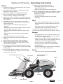
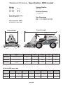
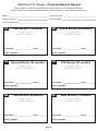
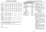
Operator’s Manual
W Series
Table of contents
Safety Instructions
2009.622
Westwood W Series – Safety Instructions
Training
Page 1
Operating Instructions
1. Read the instructions carefully. Be familiar with controls and
the use of equipment.
2. Never allow children or people unfamiliar with these
instructions to operate the mower.
Safety
Page 2
Seat Adjustment
Page 3
Ignition
Page 3
Choke
Page 3
4. The operator or user is responsible for accidents or hazards
occurring to other people or their property.
Engine Speed Control
Page 3
5. Do not carry passengers.
RPM Meter
Page 3
Hour Meter
Page 3
6. All drivers should seek to obtain professional and practical
instruction. In addition the following should be noted:
Drive Controls
Page 4
Moving Off / Reversing
Page 4
• The need for care and concentration when working with
this machine
Stopping
Page 4
Parking
Page 4
• Control of a machine sliding on a slope; control will not be
regained by applying the brake
Dump Valve
Page 4
• The main reasons for loss of control are:
Cutter On/Off Switch
Page 5
Transport Lever
Page 5
Lights
Page 5
Deck lift (manual and dial-a-height)
Page 6
Mowing Guide
3. Never mow while people, especially children or pets, are
nearby.
i. Insufficient wheel grip
ii. Driving too fast
iii. Operating on steep slopes (max 15º front wheel
drive, 25º 4WD)
iv. Incorrect load distribution
Preparation
Mulch Mowing
Page 7
High Grass Mulch Deck
Page 7
COMBI Deck
Page 7
1. Check that the machine complies with all applicable
regulations, including those in force when used on the public
highway.
Engine Maintenance
Page 8
2. When mowing, always wear substantial footwear and long
trousers. Do not operate when barefoot or with sandals.
Battery Maintenance
Page 8
Cutter Deck cleaning
Page 8
Electric Clutch to Cutter Drive Belt Tension
Page 9
Transmission Drive Belt
Page 9
Transmission Oil Tank
Page 9
Changing Cutter Decks / Deck Drive Belt
Routine Maintenance
3. Thoroughly inspect the area where the machine is to be
used and remove all stones, sticks, wires and bones or any
other foreign objects.
4. WARNING – petrol is highly flammable:
• Store fuel in containers specifically designed for this
purpose
Page 10
• Refuel outdoors only and do not smoke while refuelling
To Remove the Seat Box
Page 10
Removal of Cutter Deck
Page 11
Re-fitting the Cutter Deck
Page 11
• Add fuel before starting the engine. Never remove the
cap from the fuel tank or add petrol while the engine is
running or when engine is hot
Steering System
Page 12
• If petrol is spilled, do not attempt to start the engine but
move the machine away from the area of spillage and
avoid creating any source of ignition until petrol vapours
have dissipated
• Replace the fuel cap securely
Troubleshooting
Deck Levelling
Page 13
Tyres and Wheels
Page 14
Cutting
Page 15
5. Replace faulty silencers.
Engine and Fuel
Page 16
Electrical
Page 17
6. Before using, always inspect to see that the blades, bolts
and cutter assembly are not worn or damaged.
Supplementary Instructions
Page 18
Specifications: 2WD
Page 19
Specifications: 4WD
Page 20
Personal Service Record
Page 21
Certificate of Conformity
Page 22
7. Check the condition of the tyres and ensure that they are
inflated to the correct pressures (refer to pages 19 and 20).
This is particularly important if the machine is to be taken on
the public highway.
8. Check that the mower is in good working order, paying
special attention to brakes and steering.
9. Check that all linkages, connections and pivot nuts are
secure and that the wheel nuts are tightened correctly.
Page 1
Westwood W Series – Operating Instructions
Safety
1. Read the instructions carefully. Be familiar with controls
and the use of equipment.
2. Do not operate the engine in a confined space where
dangerous fumes can collect.
3. Mow only in daylight or in very good artificial light.
4. Before starting the engine, disengage blade and
attachment drives and apply the Park Brake.
5. Take care on slopes - maximum 15º for 2WD and 25º on
4WD models. On no account should slopes steeper than
25º be driven on.
6. Remember, there is no such thing as a ‘safe slope’.
Travel on grass slopes requires particular care to guard
against overturning:
•Do not stop or start suddenly when going up or
downhill
•Engage drive slowly. Always keep the machine in drive
when travelling up or down a slope
•Machine speed should be kept low on slopes and in
tight turns
•Stay alert for humps and hollows and other hidden
hazards
•Avoid mowing across the face of a slope
7. Watch out for traffic when crossing or working near
roadways.
8. Stop the blades rotating before crossing roadways.
9. When using the machine, never direct discharge or
material towards bystanders or allow anyone near the
machine while in operation.
10. Never operate the mower with defective guards, shields
or without protective safety devices in place and in good
working order.
11. Do not change governor settings to increase the revs
of the engine. Operating an engine at excessive speed
increases the risk of injury.
Cutting Height Adjustment Lever*
12.
13.
Before leaving the operator’s position:
•Disengage the drive to the cutter blades
•Apply the parking brake
•Stop the engine and remove the ignition key
Always disengage drive, apply the Park Brake, stop the
engine and disconnect the spark plug lead or remove
the ignition key before:
•Cleaning blockages
•Checking, cleaning or working on the mower
•Refuelling
Also:
•After striking a foreign object inspect the mower for
damage and make any repairs before restarting the
machine
•If the machine starts to vibrate abnormally, check
immediately and call your dealer if necessary
14. Reduce the throttle setting during engine run-out.
15. Never work on the mower when the engine is running.
Always:
•Use good common sense at all times and to ensure
this machine is safe and serviceable fit only original
manufacturer’s supplied spares
•Inspect the area to be cut, note the position of any
stumps, manhole covers, bumps or depressions and
avoid them to prevent damaging the blades
•Ensure the fuel tank is full before you start the
machine. We recommend the use of STANDARD
UNLEADED fuel
•Disconnect both battery terminals before attempting
any work in the engine compartment
Never:
Drive Pedals
Leave the machine running and unattended.
Ignition, Throttle Controls
and Parking Brake
Dashboard
Exhaust
Fuel Tank
Cutter Deck
Anti-scalp Wheel
Figure 1
Page 2
* Where fitted
Westwood W Series – Operating Instructions
Seat Adjustment
(Figure 2)
The seat on your Westwood W Series is adjustable forward
and backward to suit the operator. Simply lift the seat latch at
the front of the seat and slide the seat forward or backward as
appropriate. Always ensure the seat is latched into position
before driving off.
Ignition
(Figure 3)
The “key start” controls the ignition and a starter button
controls the engine start. The engine cannot be started
without the park brake being on. Insert the key and turn, then
press the start button, this will activate the starter. To stop the
engine, turn the key to the left (having first switched off the
cutter). To prevent unauthorised use, always remove the key
after use. THE IGNITION SHOULD ALWAYS BE TURNED OFF
BEFORE THE MACHINE IS RE-STARTED.
Figure 2
Figure 3
NOTE: 4WD models have an additional switch on the rear
dump valve lever. If the lever is pulled
START out the engine will not
be able to be started.
Choke
Starter button
START
(Figure 3)
Key
O
An independent choke is fitted to some
models. This choke
O
should be used in conjunction with a fast throttle setting
when starting the engine from cold. It should be cancelled as
soon as possible. Do not use the choke when starting a warm
engine.
Engine Speed Control
The lever is pushed forwards for FAST(
) and backwards
for SLOW (
). On some models the choke control is above
the fast setting, a cold engine is started on the Choke setting,
a warm one on the FAST setting. The Choke setting should be
cancelled as soon as possible. The engine should be operated
on the FAST setting at all times.
RPM Meter
P
(Figure 4)
The RPM monitor on the electronic display indicates the
engine speed. This feature should be used when the cutter
deck is engaged and in conjunction with the forward speed.
To ensure complete cutting the engine speed should not be
allowed to fall below 2600rpm, the display will flash should
this happen. If, when in use, the display does flash and the
engine speed drops below 2600rpm, there are two options:
a) Reduce forward speed b) Raise the cutting height.
Hour Meter
Choke
Engine Speed
Control
(Figure 3)
Figure 4
M / MIN
(Figure 4)
Your machine is fitted with an hour meter to assist you in
adhering to the recommended service intervals. The hour
meter only operates whilst the engine is actually running.
We recommend that your machine is serviced after 50 hours
of use or yearly, whichever comes first.
Service intervals are preset into the PCB memory and will flash
up ‘S’ on the park brake display before the service is due. This
will be reset by your dealer.
NOTE: 50 hours of mowing at 5mph equates to 250 miles of
grass cutting!
Page 3
Westwood W Series – Operating Instructions
Drive Controls (Figure 5)
Figure 5
The forward speed of the W Series is controlled by footpedal
‘A’. Reversing is controlled by footpedal ‘B’.
Moving Off / Reversing
(Figures 5 & 6)
Pedal A
To move off, ensure your feet are off pedals ‘A’ and ‘B’ and
then release the parking brake by pushing the hand lever (Fig
6) to the forward position. Now gently depress pedal ‘A’ and
you will move off. The further you depress pedal ‘A’ the faster
you will go. Its function is similar to that of a car accelerator
except that it controls the hydrostatic transmission and does
not affect the speed of the engine.
Pedal B
To reverse simply depress pedal ‘B’ and the machine will begin
to reverse. As with the forward pedal, the speed of reversing is
increased as the pedal is pushed further.
Stopping (Figure 5)
To stop the machine simply release either pedal ‘A’ or ‘B’ and
the natural braking of the hydrostatic system will bring the
machine to a stand still. For smooth braking release either
pedal gradually, for an emergency stop remove foot rapidly.
Figure 6
Parking (Figures 5 & 6)
Remove your foot from pedals ‘A’ or ‘B’ (as you would stop
normally) and then simply pull the parking brake lever (Fig 6) to
the upright position - a “P” will be indicated on the dashboard
display. When you turn off the engine, the natural braking of the
hydrostatic system will add to the effect of the brake. It’s like
leaving your car in gear.
Dump Valve
P
(Figure 7)
The natural braking of hydrostatic transmission means that it
is not possible to easily push or freewheel the W Series. To
disengage, first make certain that the machine is on a flat even
surface. Locate the Dump Valve, situated rearward of the front
right-hand wheel. Disengage by pulling out the lever. Release
the parking brake by moving the handbrake lever forward (Fig
6). You will now be able to push the W Series at a speed not
exceeding 2 mph. Make sure you disengage the Dump Valve
by pushing the lever back BEFORE starting your W Series.
Figure 7
Dump Valve (4WD Models) (Figures 7 & 8)
Dump Valve
As well as the standard valve, there is also an additional
neutral valve fitted to the 4WD W Series to allow the rear
transmission to freewheel as well. This is located on the top
left hand side of the rear transmission. To disengage the
drive pull the lever backwards. Make sure you disengage the
Neutral Valve by pushing the lever back BEFORE starting your
W Series. There is an additional safety switch fitted to the rear
dump valve lever which is connected to the Park Brake safety
system and will not allow the engine to start unless the rear
dump valve is in and the Park Brake applied.
Figure 8
– WARNING –
SERIOUS DAMAGE can occur inside the hydrostatic
transmissions if the engine is started with the
dump valves in the disengaged position.
4WD Dump Valve
Page 4
Westwood W Series – Operating Instructions
Cutter On/Off Switch (Figure 9)
The cutter switch controls the electromagnetic blade clutch.
To switch the cutter on, push the switch and then release it,
this will engage the cutter deck. To indicate that the cutter
deck is engaged, the Cutter Deck Height Indicator will flash
(Fig. 9). As an added safety feature the headlights will flash
all the time the cutter deck is running to warn other people
that the machine is cutting. To stop the cutter deck, push the
switch again. The cutter deck will only start when the operator
is sat on the seat and the Deck Transport Lever is in its
lowered position, as there are safety interlock switches fitted;
to prevent the cutter deck running in the transport position, or
if there is no one on the seat.
Cutter On/Off Switch
n/mi
!
Figure 9
A
Figure 10
Although the cutter deck is automatically switched off when
the engine is stopped or when the operator gets off the seat, it
is not good practice to rely on these features, the cutter deck
should always be switched OFF as soon as you have finished
cutting and certainly BEFORE stopping the engine or getting
off the machine. The cutter will only work whilst the operator is
sat on the seat.
Transport Lever
(Figure 10)
The Cutter Deck can be raised so the front Cutter Deck
wheels are off the ground to allow the machine to be easily
moved from one place to another. Simply lift the handle until
it latches into position. To lower the Cutter Deck once you
have reached the area you wish to mow depress the button
in the handle and lower the Cutter Deck to the ground.
n/min
!
NOTE: There is a safety interlock switch fitted to this lever
which will prevent the cutter deck from running whilst in the
raised position. It is not good practice to rely on this switch
and the cutter deck should be turned off before it is lifted into
the Transport position.
Figure 11
Lights (Figure 11)
Pressing the momentary switch turns ON the headlights.
Turn the headlights OFF by pressing the momentary switch
again. The headlights will not operate without the ignition
switch being turned on. If the headlight switch is pressed
whilst the cutter deck is running the headlights will illuminate
permanently and will revert to flashing once the headlight
switch is pressed again.
Page 5
Light switch
Westwood W Series – Operating Instructions
Dial-a-height
(Figures 12 & 13A)
Figure 12
The cutting height is adjusted by turning the rotary switch
anti-clockwise to lower the deck and clockwise to raise the
deck. The height indicator on the electronic display (Figure 13)
shows the deck position (0-lowest to 9-highest). To get the
best from this refinement use it to continuously adjust cutting
height to suit ground and grass conditions. Do not make
downward adjustments on the move until you are familiar with
the height control, this will avoid “scalping” the lawn.
Dial-a-height switch
Manual deck lift (Figure 13a)
Some W Series are fitted with a manual deck lift on the deck
instead of the dial height switch. To operate – move the
handle forward or back to achieve the right cutting height. Do
not place the deck lift to a very low setting as this may scalp
the lawn.
Figure 13
B
C
Figure 13a
Page 6
M / MIN
A
Westwood W Series – Mowing Guide
Mulch Mowing
(Figure 14)
Figure 14
Mulching can save time, avoids creating piles of rotting
cuttings and feeds your lawn. When mulch mowing it is
necessary to observe certain rules:
1. Reduce the height of the grass by no more than 1/3rd its
height in each pass. If the grass has grown long make
several passes to achieve the cut height you require.
2. Run the engine at maximum speed.
3. Mow often, particularly in spring and early summer. Short
clippings of 25mm (1") or less decompose more quickly.
4. If an unsightly residue of cuttings is being left – increase
the cutting height.
5. Drive forward at a speed that does not cause the engine
speed to drop. REMEMBER: If the RPM display flashes
below 2600rpm, there are two options:
Figure 15
a) Reduce forward speed.
b) Raise the cutting height.
6. Vary the mowing pattern from cut to cut.
7. Always keep the underside of the cutting deck clean to
ensure good grass flow.
8. Always check that the blades are sharp and in good
condition – never attempt to sharpen or replace them
yourself. New Westwood blades are not expensive; it is
good practice to ask your dealer to change them.
High Grass Mulch Deck (Figure 15)
The all round alternative when cutting long or paddock grass
is the “high grass mulch” deck. When using the high grass
mulch deck please ensure the following:
1. When cutting very tall grass set the deck at the higher
settings 7-9.
2. Drive forward at a speed that does not cause the engine
speed to drop. REMEMBER: If the RPM display flashes
below 2600rpm, there are two options:
Figure 16
a) Reduce forward speed.
b) Raise the cutting height.
COMBI Deck (Figure 16)
The combination deck includes both the mulcher and the
rear discharge in one deck. For a quick change the user
has only to place the deck in the wash position (see page
8), unscrew the handwheel and remove the top stiffener
assembly and the deck can be used as a rear discharge
deck.
Page 7
Westwood W Series – Routine Maintenance
Engine Maintenance
Please refer to the engine manufacturer’s handbook enclosed
with this manual.
Battery Maintenance
(Figure 17)
The battery fitted to your W Series is a low maintenance sealed
unit. Should your battery require charging for any reason please
note that sealed lead acid batteries require a special 2 stage
charging unit. Any battery charged on a standard battery
charger will fail prematurely. Your dealer will be able to supply
a battery charger specifically designed for the battery fitted to
your machine. The battery charger part number is 449563000.
If your W Series does not start, refer to the Troubleshooting
section in this manual.
Cutter Deck Cleaning
It is best to regularly check and clean the cutter deck as often
as possible. This can be made easier by putting the cutter deck
into the ‘wash’ position (see below) or by removing the cutter
deck (follow instructions on page 11).
Before putting the cutter deck to the wash position ensure the
machine is parked on level ground and the park brake applied
(this operation is easier if carried out on a firm surface e.g.
concrete or tarmac).
1. Lower the cutter deck to the ground using the ‘transport
lever’ and set the height of cut to 0 or 1 on the dial-a-height
display or on the manual deck lift. (Figures 12 & 13A page 6)
2. Remove the deck belt cover by undoing the M5 Bolt
using a 3mm hexagon key wrench. Note supplied with the
instruction booklet will be a hand wheel to use instead of the
M5 bolt if required. (Figure 18)
3. Undo the actuator connector at the back of the cutter deck
if tractor has a dial-a-height (damage to the connector
will occur if the cutter deck is removed or put in the wash
position with the actuator still connected).
4. Release the deck belt tension by pulling the lever located
under the LH foot plate towards the front of the tractor.
Remove the drive belt and put the lever back in tensioned
position. (Figures 19 and 20)
5. Pull and push the two spring latches towards the tractor so
that they lock in place. (Figures 21 and 22)
6. Pull the cutter deck forward until the arms reach the end of
the slots and then lift into the wash position. (Figure 23)
7. The Cutter deck is now ready to be cleaned. Standard hose
pressure is all that is required to remove grass from the
deck if done shortly after cutting has finished. Countax do
not recommend the use of a pressure washer. If used any
damage caused will not be covered by warranty.
Figure 17
The battery in your Countax is very similar to that found in your car. To remove,
simply undo the NEGATIVE terminal connection, followed by the positive.
Figure 18
M5 Bolt
Figure 19
Figure 20
Tensioned
Figure 21
Locked
De-Tensioned
Figure 22
Unlocked
To re-fit the cutter deck follow the instructions below:
1. Lower the cutter deck and slide it under the front of the
machine making sure the two tongue plates are placed in
their original position.
2. Re-fit the deck belt to the pulley ensuring the lever is pulled
forward into the un-tensioned position.
3. Lock the two spring pins back in place by simply pulling
them out of their lock position.
4. Re-fit the actuator connector to the socket on the machine
Figure 23
(if fitted).
5. Re-tension the deck belt by moving the deck belt tension
WARNING: DO NOT SPRAY WATER DIRECTLY
lever backwards until the deck is taught.
ONTO BEARING HOUSINGS
6. Finally re-fit the deck belt cover using the M5 bolt and 3mm
hexagon key.
Page 8
Westwood W Series – Routine Maintenance
Electric Clutch to Cutter Drive
Belt Tension
Figure 24
The Deck drive belt is self tensioned. When the deck tension
lever is in the tensioning position, the belt will retain its tension
correctly. If there is a problem with the tension of the deck
drive belt, then check that the belt used is the correct one.
Transmission Drive Belt
The transmission drive belt is self-tensioning. When the hand
brake is released and the drive belt engaged, the belt will
retain its tension correctly. When the drive is dis-engaged, by
applying the hand brake, the park brake engages. This setting
is adjustable but adjustments should be carried out by your
dealer. Anyone not familiar with this setting may cause serious
damage to the transmission.
Transmission Oil Tank 2WD
(Figure 24)
This is located under the front foot plate and can be seen
by lifting the seat and removing the toolbox, it should be
approximately half full when the machine is cold. The oil
will expand when the engine is warm. It should return to the
half way point once the machine has cooled down. The oil
should not need to be topped up in normal use. If it does need
topping up, it can be filled by undoing the rubber grommet in
the plastic main body. If a noticeable drop in the level occurs
then your dealer should be contacted.
Page 9
Transmission Oil Tank
Westwood W Series – Routine Maintenance
Changing Cutter Decks
and /or Deck Drive Belt
To Remove the Seat Box (if required)
Before changing the Cutter Deck ensure the Machine is
parked on level ground and the Handbrake applied (This
operation is easier if carried out on a firm surface e.g.
Concrete or Tarmac). 1. Undo the two M8 bolts (13mm spanner) on the back of
the seat box
This operation is easier if the battery is removed first.
2. Unclip the two wires from the seat switch under the seat.
Referring to the Cutter Deck removal instructions remove the
Cutter Deck and place to one side.
To change the Cutter Deck Drive Belt (Cutter Deck MUST
be removed) please follow the instructions below:
1. Lift the seat up and remove the Tooltray. Release the lever
on the top Jockey pulley plate to relieve the tension on the
belt spring. Unhook the spring from the spring bracket.
2. Move to the front of the machine and remove the engine to
Electric Clutch belt from the top pulley.
3. Undo the 2 terminals on the electric clutch (pull on the
plastic terminal and not the cable).
3. Lift the seat box up at the back and slide the seat box
out.
To re fit:
1. Slide the seatbox back onto the two bosses at the front.
Re fasten the two seat switch wires (orientation is not
important)
2. Re fit the two M8 bolts.
NOTE: if the seat switch wires are not re fitted the engine will
cut out when the park brake is released.
Figure 25
4. Undo the M8 nut and bolt (13mm spanner or socket)
securing the Clutch Retaining pin and remove. Note which
slot the pin was in, as on re assembly it must be put in the
same slot.
5. The Cutter Deck drive belt can now be removed.
6. Fit the new Deck Drive Belt to the Electric Clutch see the
table below for Deck sizes and Belts.
7. Re-fit the Clutch retaining pin in its original position. And
ensure the M8 nut and bolt are tight.
8. Refit the engine to Electric Clutch belt and re fit the spring
if it was removed.
9. Replace the two connectors on the electric clutch (They
can go either way round).
10.Refit the engine to Electric Clutch belt on the top pulley.
Then re tension the belt by re fitting the spring and putting
the lever into the tensioned position (Ensure the belt is still
on the engine pulley as it can sometimes fall off)
Fit the Cutter Deck referring to the Cutter Deck Fitting
Instructions and re check the belt tension.
Cutter Deck
Deck Drive Belt part No
used on new cradle
Deck Drive Belt Part No
used on old cradle
38” Mulch
228986300
229503900
44” Mulch
228986300
22940100
50” Mulch
228986300
22950500
36 HGM
228986300
22949800
42 HGM
228986300
22871200
38” COMBI
228986300
N/A
44” COMBI
228986300
N/A
50” COMBI
228986300
N/A
Page 10
Westwood W Series – Routine Maintenance
Removal of Cutter Deck
M5 Bolt
The Cutter Deck can be easily removed and refitted if
required to aid cleaning or for transportation. Before
removing the Cutter Deck ensure the machine is parked
on level ground and the handbrake applied (This operation
is easier if carried out on a firm surface e.g. concrete or
tarmac).
To remove the cutter deck, please follow the instructions
below:
1. Lower the Cutter Deck to the ground using the Transport
lever and set the height of cut to 0 or 1 on the Dial Height
Display.
2. Remove the Deck belt cover by undoing the M6 Bolt using
a 3mm hexagon key wrench.
3. Undo the Actuator connector at the back of the Cutter
Deck. (Figure 28) ( Damage to the connector will occur
if the Cutter Deck is removed with the Actuator still
connected).
Deck Pin
Figure 26
4. Release the Deck belt tension by pulling the Deck Tension
lever forward.
Unsecured
Figure 19
Secured
5. Remove the Deck Drive Belt from the Deck Pulley.
6. Pull and push the two spring latches towards the tractor so
that they lock in place (Figure 27)
7. Undo the Rue Clip (Figures 26A & 26B) and remove the
front Deck Pin. THE LIFT LINKAGE HAS STRONG LIFT
SPRINGS AND WILL SPRING UPWARDS ONCE THE PIN
IS REMOVED! To aid the removal of the front Deck Pin hold
the front lift linkage down with your other hand.
Figure 26A
8. Pull the Cutter Deck forward and the Tongue will come out
of its slots in the lift linkage and the Cutter Deck is now free
of the Machine.
Figure 26B
Spring latches
Refitting the Cutter Deck
1. Slide the Cutter Deck under the front of the machine lining
up the cradle on the back of the deck with the slot in the lift
linkage.
Figure 27
2. Re fit the Deck Belt to the Pulley
Figure 28
3. Pull the front linkage down so it lines up with the front lift
bracket and fit the Deck Lift Pin and Rue Clip ensuring the
Rue Clip is in its locked position (Figure 26B).
4. Re fit the Actuator connector to the socket on the Machine.
5. Lock the two spring pins back in place by simply pulling
them out of their lock position.
6. Re-tension the deck belt by moving the deck belt tension
lever backwards until it is flush with the deck lift linkage.
7. Finally refit the deck belt cover using the M5 bolt and 3mm
hexagon key.
Page 11
Westwood W Series – Routine Maintenance
Steering System
The steering on your W Series is controlled by a cable and
chain assembly. This should not require any maintenance in
normal use. The tension and condition of the chain cable and
associated parts will be checked on the machine’s annual
service by your dealer. However should you wish to check and
adjust the tension please follow the instructions below:
Figure 29
kg
7kg (15lb)
1. Apply the Park Brake and set the steering to the straight
ahead position.
2. Select the midway position on the cable (just behind the
front wheel ) and using a spring balance apply a 7kg (15lbs)
pull. Using a ruler or tape measure the deflection achieved
which should be 10mm (3/8"). If the measurement is more
then the tension should be increased and if less decreased.
To adjust the tension proceed as follows
mm
3. Using two 13mm spanners slacken the two nuts on the rear
steering pulley.
4. Using a 1/4" spanner hold the hexagonal part of the cable
adjuster and wind the nut onto the adjuster to tighten the
cable and off the adjuster to slacken.
NOTE: this will alter the position of the steering wheel so
ensure each adjuster on either side of the steering pulley is
adjusted equally.
5. Check the tension is correct after performing the
adjustment.
6. Finally lock the two nuts on the adjuster together to prevent
the nuts undoing in use.
Figure 30
Page 12
Steering Tension Settings
10 mm
(3/8”)
Westwood W Series – Troubleshooting (Deck Levelling)
For the best results when Mulch Mowing it is advisable to
have the front of the cutter deck raised 8-10mm higher than
the back of the cutter deck – and should be the defualt
setting. This allows a better airflow through the cutter deck,
which keeps the grass cuttings up in the air for longer,
allowing the blades to cut the grass more finely. This in turn
produces a better mulch, which is more easily absorbed
by the grass. To ensure an even cut the deck must be level
side to side with no more than a 3mm difference between
the sides when measured on a flat even surface. If it is
necessary to check or alter the level settings on your Cutter
Deck please follow the instructions below.
Figure 31
NOTE: The diagram shows a 38" Mulching Cutter Deck, but
all decks have similar adjustments.
To check the Cutter Deck is set correctly
Park the machine on a hard level surface, and lower the
cutter deck to the floor using the Cutter Deck lift lever and
set the cut height to 9. Apply the park brake.
8-10mm higher than at the
back of the cutter deck
Measure the height from the top of the cutter deck on either
side (points A & B) and if they are within 3mm (1/8") measure
points C and D, where C should be 8-10 mm (5/16"- 3/8")
higher than D. If these are both correct your cutter deck
is set correctly. If there is a discrepancy then follow the
instructions below to correctly level the cutter deck.
Cutter Deck Level Adjustment
The cutter deck level is set by adjusting the four M10 rod
ends on the two level rods. The rods run along either side of
the cutter deck.
To adjust the side to side level (points A & B) slacken off
the M10 lock nut (17mm spanner) behind a front rod end (1)
then undo the M10 nut and bolt which fasten the rod end to
the castor assembly. The cutter deck will sag when this bolt
is removed and may need to be supported to enable easy
removal of the bolt.
To raise the side the rod is on wind the rod end in and to
lower wind the rod end out. NOTE: as you raise or lower
one side the other side will lower or raise. We suggest that
you wind the trunnion on a maximum of two turns and then
re fit the M10 bolt and check the level. If there is insufficient
adjustment slacken off the M10 lock nut on the other end of
the rod you are adjusting and adjust the rod in or out of the
rod end. Once the adjustment is correct then ensure all nuts
and bolts are tight and that the rod ends can move on the
bolts.
Once the side to side adjustment is correct check the front
to back adjustment and if incorrect raise or lower the front
by unscrewing the rod ends an equal amount on each rod in
the same direction.
Figure 32
Page 13
Westwood W Series – Troubleshooting (Tyres and Wheels)
Persistent flat tyres
Removal of rear wheel
This is an inevitable problem faced by around 5% of
Westwood users. Like all garden machinery, the most
common cause of punctures is THORNS! Blackthorn,
Hawthorn and Rose are usually at the bottom of the problem
and will puncture any tyre not fitted with very expensive
guards. There are less expensive ways to overcome this
problem and it is advisable to check and avoid these possible
causes:
2WD REMOVAL OF REAR WHEEL
Has the rim of the wheel been damaged causing the seal on
the tube-less tyre to be broken. There are two solutions:
After removing the hub cap with the aid of a screwdriver, follow
steps 1 - 3 as indicated with the front wheels.
Use a 19mm socket or wheel wrench and loosen the nut in
the centre of the wheel. DO NOT REMOVE IT WHILST THE
MACHINE IS ON THE GROUND. Raise the rear of the machine
(Fig 34), remove the nut and carefully remove the wheel. Take
care not to dislodge the machine from the jack.
After the repaired wheel has been refitted lower the machine
to the ground and tighten the wheel nut to a torque setting of
5.25kg/m (38lb/ft). Then refit the plastic hub cap.
4 If the damage is not severe, treat with Westwood Tyre
Sealant (Part No. 52903501).
4 If the damage is significant it is necessary to order a new
wheel from your dealer.
Figure 33
If you have Hawthorn, Blackthorn or Wild Rose in your
garden – this will puncture any tyre. It makes sense to check
any area you intend to cut or drive over and to remove any
branches. THE LONG-TERM SOLUTION IS TO TREAT ALL
FOUR TYRES WITH Westwood TYRE SEALANT – FOLLOW
THE INSTRUCTIONS ON THE BOTTLE.
If your tyres spin or lose grip
CHECK:
4 That all tyres are inflated to their correct pressures (see
pages 19 and 20).
4 Are you going too fast for the conditions?
Removal of front wheel
Figure 34
2WD REMOVAL OF FRONT WHEELS
4WD REMOVAL OF FRONT AND REAR WHEELS
1. Apply parking brake, place chocks under the wheels that
are to remain on the ground.
2. Use a 19mm socket or wheel wrench and loosen the
four wheel nuts. DO NOT REMOVE THEM WHILST THE
MACHINE IS ON THE GROUND.
3. Place a lifting jack under the relevant jacking point front or
rear as required and jack the machine up until the wheel is
clear of the ground.
4. Remove the 4 wheel nuts and place them somewhere safe.
5. Carefully remove the wheel taking care not to dislodge the
machine from the lifting jack.
Figure 35
6. Once the tyre has been repaired replace the wheel onto the
studs and screw the 4 wheel nuts back on by hand.
7. Lower the machine to the ground and tighten all four wheel
nuts to a torque setting of 5.25kg/m (38lb/ft). Remove the
chocks from under the other wheels.
If the machine is to be left with the wheel removed for any
length of time it is advisable to place an axle stand under the
machine and remove the lifting jack.
Page 14
Westwood W Series – Troubleshooting (Cutting)
The information contained on this, and the following pages
is given on the understanding that Westwood accepts no
responsibility for work carried out by a customer or for any
damage thus caused, whether or not the service instructions
have been misunderstood. To be sure that your warranty
terms are not breached, service work should only be carried
out by your dealer.
Check:
4 That the Belt Tension Lever is correctly applied (Page 8,
Figures 19 and 20).
4 That the Cutter Deck is not clogged with wet cuttings.
4 That the Cutter Drive Belt is not worn.
Cutter fails to start or cuts out when
switched on
Check:
4 Are you on the machine? – Unless you sit on the seat, the
safety switch cuts out the Cutter Deck.
4 That either the Cutter Switch or the Safety Switch on the
seat is not faulty – if so, call your dealer.
4 Is the battery low? – The Clutch Engage Switch will only
operate if the battery is well charged.
4 The transport lever is in its lowered position. In the raised
position the safety switch inhibits the operation of the
cutter deck.
Uneven Cutting
Check:
We do not recommend that customers attempt to change
cutting blades themselves, remember that it is never
worthwhile to have blades re-ground. It is cheaper and better
to replace blades – re-grinding is likely to affect the hardening
of the blade and its balance.
The Cutter Deck should be set so that it is parallel to the
surface it is cutting with a maximum variation from side to side
of 3mm. The front of the mulching deck should be 8-10mm
higher than the back. Check this by placing the X-Series on a
hard level surface and measuring the clearance heights front
to back and side to side with a steel ruler or tape, with the
Cutter set one adjustment up from its lowest position (page
13).
If the Cutter Deck seems to require
levelling, first check these other possible
causes:
4 That all tyres are inflated to their correct pressures.
The cutter seems to lose power and the
belt slips and overheats
FRONT: 0.7-1.1KGF/cm(10 - 12 PSI)
BACK: 0.7-1.1KGF/cm (10 - 12 PSI)
4 That the deck is level from side to side and back to front
(see Cutter Deck Levelling).
4 Are the tyres correctly inflated? – If not, rectify using the
figures on pages 19 and 20 as a reference.
4 That one or more of the cutter blades are not worn or
damaged – if this is the case, it is necessary to call your
Countax dealer.
Check:
4 Is the Cutter deck moving freely front to back and side
to side? The Cutter Deck should rock from side to side
if lifted on one side ( check this carefully as the cutter
deck is heavy) and the Deck Transport Lever should
move approximately a ¼ of the way up, its slot, with the
machine on level ground, before the cutter deck starts to
lift showing that there is sufficient free play in the system.
If this is not the case check for damage and whether
anything is trapped in the deck lift system.
4 That the tyres are all inflated to the correct pressures (see
above).
4 Is there any impact damage that has bent or distorted the
Deck or Suspension Brackets (a matter for your dealer).
4 The liner is full of grass.
Uneven cut (cuts shorter one side than
the other)
4 That the rear axle is pivoting freely.
4 That the deck suspension brackets are moving freely and
not hitching up.
4 That the side deck level adjustment is correct (page 13).
Cut is uneven or untidy in one or
more sectors
Check:
4 That the Cutter Deck is levelled correctly front to back
(page 13).
4 That one or more of the blades are not worn or damaged
– if so, call your dealer.
4 The liner is full of grass.
Page 15
Westwood W Series – Troubleshooting (Engine & Fuel)
Engine fails to turn over
Low fuel warning
CHECK:
When the petrol gets low a warning will appear on the dash to
remind you to fill up again as the machine is about to run out of
petrol.
4 That the parking brake is on and that you are sitting on
the seat.
(Figure 37)
4 4WD only - The rear Dump Valve lever is pushed in and is
operating the dump valve switch.
4 That the battery terminals are connected (Page 8).
4 That fuse 2 (yellow 20amp ignition fuse) has not blown or
been dislodged.
4 That the battery is charged.
4 30amp fuse on the loom near the engine has not blown.
IF THIS IS NOT THE CASE CONTACT YOUR DEALER.
If the engine turns over and does not
start
CHECK:
4 That the fuel tank is full and the Petrol Tap is turned ON
(if fitted).
4 That the spark plug lead is connected.
Figure 36
4 That the spark plug is clean and set to the correct gap
(see engine manufacturer’s handbook for relevant spark
plug data).
Figure 37
4 That the fuel filter is not blocked (see engine
manufacturers handbook – Air and Cooling).
4 That fuse 5 (red, 10amp) has not blown or been
dislodged.
IF THIS IS NOT THE CASE CONTACT YOUR DEALER.
10
10
10
10
10
20
10
4 That the Air Filter Pre-cleaner is not blocked (see engine
manufacurers handbook – Air and Cooling)
20
4 That you have not run out of fuel.
20
CHECK:
20
If the engine misfires, loses power or
stalls in use
4 That the cooling air intakes are not blocked.
4 If the ignition lights have gone off – check yellow 20amp
fuse, fuse 2 on the fuse holder.
4 That fuse 5 (red, 10amp) has not blown or been
dislodged.
4 That the 30amp loom fuse has not blown.
IF THIS IS NOT THE CASE CONTACT YOUR DEALER.
If the cutter deck fails to operate
CHECK:
4 That fuse 3 on the fuse holder (red 10amp clutch fuse) has
not blown.
4amp Circuit Breaker
Figure 38
4 Whether you have got off the seat – the safety switch will
disengage the cutter.
4 If the battery has lost charge and will no longer hold the
clutch in operation.
4 That the transport lever is in the lowered position.
IF THIS IS NOT THE CASE CONTACT YOUR DEALER.
Page 16
Westwood W Series – Troubleshooting (Electrical)
Display fails to turn on
Figure 39
CHECK:
4 That the 30 amp fuse on the loom has not blown. This is
located at the back of the machine on the left hand side of
the engine under the bonnet.
W Series Fuse Box
Location
4 That the battery terminals are connected and there is
sufficient charge in the battery.
4 That Fuse 2 (Yellow 20Amp Ignition Fuse) in the fuse holder
has not blown or become dislodged.
If the Electric Deck Lift on your W Series
fails to operate:
10
10
10
10
10
20
10
20
4 That nothing has become jammed between the cutter deck
and your W Series Chassis. (Figure 31)
20
4 The 4amp contact breaker has not tripped out. This can
be reset after approximately 30 seconds by pushing in the
small black button on the top of the contact breaker.
20
CHECK:
10
10
10
20
10
10
20
10
20
If “C” appears in the Park Brake
window for more than two minutes. This
indicates that the battery is not charging
20
IF THIS IS NOT THE CASE CONTACT YOUR DEALER.
CHECK:
4 The main charge fuse has not blown
IF THIS IS NOT THE CASE CONTACT YOUR DEALER.
4amp contact breaker
Figure 40
Page 17
Westwood W Series – Supplementary 4WD Instructions
Electronic Slope Alert (ESA)
Figure 41
If your W Series is fitted with 4WD it will have ESA. This is set
to an angle of 25° at the factory. If this angle is exceeded then
the display will flash 25°, and a warning siren will sound.
The exceptional traction of 4WD will allow you to cut in very
slippery conditions, and it also allows the machine to ascend
very steep slopes. If the slope alarm sounds DO NOT attempt
to cut or drive at a greater angle than the one you are on. As all
terrains and conditions vary, great care should be maintained
when operating the machine. DO NOT take the machine into
an area where it could become unstable.
On no account should slopes steeper than 25° be driven on.
Figure 42
Dump Valve (4WD Models) (Figure 42)
As well as the standard valve, there is also an additional
neutral valve fitted to the 4WD W Series to allow the rear
transmission to freewheel as well. This is located on the top
left hand side of the rear transmission. To disengage the
drive pull the lever backwards. Make sure you disengage the
Neutral Valve by pushing the lever back BEFORE starting your
W Series. There is an additional safety switch fitted to the rear
dump valve lever which is connected to the park brake safety
system and will not allow the engine to start unless the rear
dump valve is in, and the park brake applied.
Transmission Oil Tank
4WD Neutral Valve
Figure 43
(Figure 43)
This is located under the right hand control pod of the W
Series and should be approximately half full when the machine
is cold. The oil will expand when the engine is warm. It should
return to the half way point once the machine has cooled
down. The oil should not need to be topped up in normal use.
If a noticeable drop in the level occurs then your dealer should
be contacted.
MAX
- WARNING -
MIN
SERIOUS DAMAGE can occur inside the hydrostatic
transmissions if the engine is started with the
dump valves in the disengaged position.
Page 18
Westwood W Series – Specification: 2WD models
Weight
W15 250.5 kg
Turning Radius
W16 260 kg
2WD 63.5cm
W20 265 kg
Forward Speeds
Fuel Tank Capacity
0 - 9.6 kph max
14 litres (3 gallons)
Tyre Pressures
Transmission
Front: 0.7-1.1 KGF/cm (10-12 psi)
Tuff Torq K46 Hydrostatic or K46cm
Rear: 0.7-1.1 KGF/cm (10-12 psi)
K574 - 2WD with power steering
K574 - 4WD or C.S.U.
Overall Length
Overall Width
1.75m
X- SERIES
CTX
Engine
Displacement
Power
Torque
Bore
Stroke
W15
15.5hp (11.56kW) Briggs & Stratton
Single Cylinder
465cc
9.32kW 12.5hp
24.5NM
87.3mm
77.7mm
W16
16hp (11.93kW) Briggs & Stratton
V-Twin Cylinder Vanguard
480cc
11.93kW 16hp
32.5NM
68mm
57mm
W20
20hp (14.91kW) Briggs & Stratton
V-Twin Cylinder Vanguard
570cc
14.91kW 20hp
40NM
72mm
66mm
W Series sizes table
97cm (38")
Mulch deck
112cm (44")
Mulch deck
97cm (38")
Combi deck
112cm (44")
Combi deck
92cm (36")
HGM deck
107cm (42")
HGM deck
Overall Length (A)
2.315m
2.380m
2.315m
2.380m
2.420m
2.483m
Overall Length (B)
1.110m
1.250m
1.110m
1.250m
1.115m
1.247m
Page 19
CTX
1.12m
Model
Westwood W Series – Specification: 4WD models
Weight
Turning Radius
W16-4WD
W20-4WD
W25-4WD
290 kg
295 kg
295 kg
4WD 77cm
Forward Speeds
0 - 9.6 kph max
Fuel Tank Capacity
Tyre Pressures
14 litres (3 gallons)
Front: 0.7-1.1 KGF/cm (10-12 psi)
Rear: 0.7-1.1 KGF/cm (10-12 psi)
Transmission 4WD
Tuff Torq K57 & K574 KTMI
Overall Length
Overall Width
1.75m
X- SERIES
CTX
Engine
Displacement
Power
Torque
Bore
Stroke
W16-4WD
16hp (11.93kW) Briggs & Stratton
V-Twin Cylinder Vanguard
480cc
11.93kW 16hp
32.5NM
68mm
57mm
W20-4WD
20hp (14.91kW) Briggs & Stratton
V-Twin Cylinder Vanguard
570cc
14.91kW 20hp
40NM
72mm
66mm
W25-4WD
Kawasaki Twin Cylinder V-Twin
18.64kW
675cc
18.64kW 25hp
41.1NM
75.2mm
76mm
W Series 4WD sizes table
97cm (38")
Mulch deck
112cm (44")
Mulch deck
127cm (50")
Mulch deck
97cm (38") 112cm (44") 127cm (50")
Combi deck Combi deck Combi deck
Overall
Length (A)
2.315m
2.380m
2.408m
2.315m
2.380m
Overall
Length (B)
1.110m
1.250m
1.398m
1.110m
1.250m
Page 20
92cm (36")
HGM deck
107cm (42")
HGM deck
2.408m
2.420m
2.483m
1.398m
1.115m
1.247m
CTX
1.12m
Model
Westwood W Series – Personal Service Record
Use this page as a personal record of the service history of your Westwood W Series.
Ask your dealer to stamp the appropriate box at the same time as your Service Record Card.
Model
Name of Dealer
Date of Purchase
Serial Number
Date of Registration
1st
First Service (12 months)
4th
DEALER STAMP
OR NAME & ADDRESS
DEALER STAMP
OR NAME & ADDRESS
Service Date:
Hours:
Fourth Service (48 months)
Service Date:
Dealer’s Signature:
Dealer’s Signature:
2nd
5th
Second Service (24 months)
DEALER STAMP
OR NAME & ADDRESS
Service Date:
Hours:
Fifth Service (60 months)
DEALER STAMP
OR NAME & ADDRESS
Service Date:
Dealer’s Signature:
Dealer’s Signature:
3rd
6th
Third Service (36 months)
DEALER STAMP
OR NAME & ADDRESS
Service Date:
Dealer’s Signature:
Hours:
Hours:
Hours:
Sixth Service (72 months)
DEALER STAMP
OR NAME & ADDRESS
Service Date:
Dealer’s Signature:
Page 21
Hours:
Certificate of Conformity
Model
W15
W16
W16-4WD
W20
W20-4WD
W25-4WD
Power (kw)
11.56
11.93
11.93
14.91
14.91
18.64
3000rpm
3000rpm
3000rpm
3000rpm
3000rpm
3000rpm
Briggs & Stratton
Briggs & Stratton
Briggs & Stratton
Briggs & Stratton
Briggs & Stratton
Kawasaki
Engine Type
PETROL
PETROL
PETROL
PETROL
PETROL
PETROL
Mass in Kg
250.5
260
290
265
295
295
Max. Sound Power Level
100dB(A)
99dB(A)
99dB(A)
100dB(A)
100dB(A)
100dB(A)
Type of Cutting Device
Cutterbar
Cutterbar
Cutterbar
Cutterbar
Cutterbar
Cutterbar
97cm
97cm
112cm
112cm
112cm
112cm
Engine Operating Speed
Engine Manufacturer
Std. Width of Cutting Device
Conformity assessment procedure: According to EC Noise Directive 2000/14/ec
Notified Body: Intertek Research & Performance Testing, Davy Avenue, Knowhill, Milton Keynes MK5 8NL
Standards applied: Machinery Directive – 2006/42/EC
Noise Directive (2000/14/EC) 92/59/EEC using BS EN ISO 12001-2:2003 Safety of machinery. (Basic concepts,
general principles for design Technical principles) and BS 294:1992
BS EN 836:1997 Garden equipment. Powered lawnmowers. Safety
The undersigned, representing the manufacturer, herewith declares the product conforms with the standards
shown herewith.
SIGNED:
Harry Handkammer
Managing Director
Place of Declaration: Oxford, England
Page 22
Date of Declaration: 05/01/10
Westwood Tractors, Freepost SCE11744, Admail 3376, Plymouth, Devon, PL7 5ZY
Tel: 0800 0720127 • Fax: 0800 0720132