1
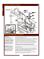
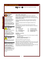
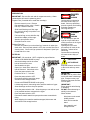
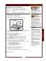
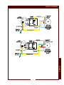
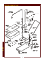
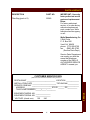
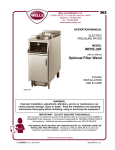
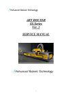
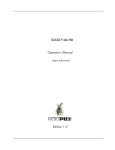
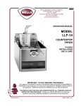
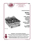
439
OPERATION MANUAL
MODEL
WOF-80
WOF-80 Oil Filtration Unit
(wands shown stowed)
Cooking Oil
Filtration System
for use with
WFPE-68KFC
Pressure Fryer
Includes
INSTALLATION
USE & CARE
IMPORTANT: DO NOT DISCARD THIS MANUAL
This manual is considered to be part of the appliance and is to be given to the OWNER or
MANAGER of the restaurant, or to the person responsible for TRAINING OPERATORS of
this appliance. Additional manuals are available from your WELLS DEALER.
THIS MANUAL MUST BE READ AND UNDERSTOOD BY ALL PERSONS USING OR
INSTALLING THIS APPLIANCE. Contact your WELLS DEALER if you have any
questions concerning installation, operation or maintenance of this equipment.
p/n 305728 Rev. A
M439 060403 cps
LIMITED WARRANTY STATEMENT
GENERAL
been modified, misused, misapplied, improperly installed, or
damaged in transit or by fire, flood or act of God.
It also
does not apply if the serial nameplate has been removed or
service is performed by unauthorized personnel. The prices
charged by Wells for its products are based upon the
limitations in this warranty. Seller’s obligation under this
warranty is limited to the repair of defects without charge by
Wells’ factory authorized service agency or one of its
sub-agencies. In addition to restrictions contained in this
warranty, specific limitations are shown in the Service Policy
and Procedure Guide. Please consult your classified telephone
directory, your foodservice equipment dealer or for information and
other details concerning warranty write to:
GLOBAL WARRANTY STATEMENT for:
YUM! Restaurants International and YUM Brands Inc.
This WOF-80 Cooking Oil Filtration System manufactured by
Wells Manufacturing Company exclusively for KFC is
warranted against defects in materials and workmanship for
a period of two years from the date of original installation.
THE FOREGOING OBLIGATION IS EXPRESSLY GIVEN
IN LIEU OF ANY OTHER WARRANTIES, EXPRESSED OR
IMPLIED, INCLUDING ANY IMPLIED WARRANTY OF
MERCHANTABILITY OR FITNESS FOR A PARTICULAR
PURPOSE, WHICH ARE HEREBY EXCLUDED.
WELLS MANUFACTURING COMPANY, A DIVISION OF
CARRIER COMMERCIAL REFRIGERATION INC., SHALL
NOT BE LIABLE FOR INDIRECT, INCIDENTAL OR
CONSEQUENTIAL DAMAGES OR LOSSES FROM ANY
CAUSE WHATSOEVER.
This warranty is void if it is determined that upon inspection
by an authorized service agency that the equipment has
Service Parts Department
Wells Manufacturing Company
P.O. Box 280
Verdi, NV 89439
Phone (775) 689-5700
Fax: (775) 345-0569
SERVICE POLICY AND PROCEDURE GUIDE
ADDITIONAL WARRANTY EXCLUSIONS
1.
Resetting the safety overload protector unless
warranted conditions are the cause.
2.
All problems due to operation at voltages other than
specified on equipment nameplates – conversion to
correct voltage and phase are the customer’s
responsibility.
3.
All problems due to electrical connections not made
in accordance with electrical code requirements and
wiring diagrams supplied with the equipment.
4.
Replacement of items subject to normal wear to
include such items as: knobs and couplings. Normal
maintenance functions including cleaning are not
covered by warranty.
5.
6. Travel mileage is limited to sixty (60) miles from an
Authorized Service Agency or one of its sub-agencies.
7. All labor shall be performed during regular working
hours. Overtime premium will be charged to the buyer.
8. All genuine Wells replacement parts are warranted
for ninety (90) days from the date of purchase on
non-warranty equipment. This parts warranty is limited
only to replacement of the defective part. Any use of
non-genuine Wells parts completely voids any
warranty.
9. Installation, labor and job checkouts are not
considered warranty.
10. Charges incurred by delays, waiting time or operating
restrictions that hinder the service technicians’ ability to
perform service are not covered by warranty.
This includes institutional and correctional facilities.
Full use, care and maintenance instructions are
supplied with each machine. Those miscellaneous
adjustments noted are customer responsibility. Proper
attention will prolong the life of the machine.
SHIPPING DAMAGE CLAIM PROCEDURE
NOTE: For your protection, please note that equipment in
this shipment was carefully inspected and packaged
by skilled personnel before leaving the factory. Upon
acceptance of this shipment, the transportation company
assumes full responsibility for its safe delivery.
IF SHIPMENT ARRIVES DAMAGED:
1. VISIBLE LOSS OR DAMAGE: Be certain that any
visible loss or damage is noted on the freight bill or
express receipt, and that the note of loss or damage is
signed by the delivery person.
2. FILE CLAIM FOR DAMAGE IMMEDIATELY:
Regardless of the extent of the damage.
3.
CONCEALED LOSS OR DAMAGE: if damage is
unnoticed until the merchandise is unpacked, notify the
transportation company or carrier immediately, and file
“CONCEALED DAMAGE” claim with them. This
should be done within fifteen (15) days from the date
the delivery was made to you. Be sure to retain the
container for inspection.
Wells Manufacturing cannot assume liability for damage or
loss incurred in transit. We will, however, at your request,
supply you with the necessary documents to support your
claim.
xi
WARRANTY
SPECIFICATIONS
FEATURES & OPERATING CONTROLS
PRECAUTIONS & GENERAL INFORMATION
AGENCY LISTING INFORMATION
INSTALLATION
OPERATION
CLEANING INSTRUCTIONS
TROUBLESHOOTING SUGGESTIONS
WIRING DIAGRAMS
EXPLODED VIEW and PARTS LIST
PARTS & SERVICE
CUSTOMER SERVICE DATA
xi
1
2
3
4
4
5
7
8
9
10
11
11
INTRODUCTION
Thank You for purchasing this Wells Manufacturing Co. appliance.
Proper installation, professional operation and consistent maintenance of this appliance will ensure that it
gives you the very best performance and a long, economical service life.
This manual contains the information needed to properly install this appliance, and to use and care for the
appliance in a manner which will ensure its optimum performance.
SPECIFICATIONS
MODEL
VOLTS
WATTS
AMPS
POWER SUPPLY CORD
WOF-80
115V 50/60 Hz
460
4.0
NEMA 5-15P
WOF-80EU
220 - 240V
50/60 Hz
725 - 790
3.3
CORD PROVIDED
WITHOUT PLUG
MODELS WOF-80 and WOF-80EU DIMENSIONS:
HEIGHT:
28" (710 mm) with wands stowed
46-11/16" (1185 mm) with discharge wand in place
WIDTH:
20" (508 mm) overall
DEPTH:
36-1/2" (926 mm) with wands stowed
43-3/4" (1110 mm) with discharge wand in place
OIL RESERVOIR CAPACITY:
76 pounds (34.5 Kg)
1
GENERAL
TABLE OF CONTENTS
FEATURES & OPERATING CONTROLS
GENERAL
PRECAUTIONS AND GENERAL INFORMATION
IMPORTANT:
The technical content of this
manual, including any
troubleshooting suggestions,
parts breakdown illustrations,
wiring diagrams, schematics,
servicing instructions and/or
adjustment procedures, is
intended for use by qualified
technical personnel only.
Wells WOF-80 cooking oil filtration system is intended for use in
commercial establishments only.
IMPORTANT: Cleanliness of
this oil filtration system is
essential to good sanitation.
Read and follow all included
cleaning instructions and
schedules to ensure the
safety of the food product.
Any procedure which requires the use of tools must be performed by a
qualified technician.
This device is designed for use in conjunction with the Wells Model
WFPE-68KFC Pressure Fryer to filter hot cooking oil. No other use is
recommended or authorized by the manufacturer or its agents.
Operators of this oil filtration system must be thoroughly trained in the
appliance use, precautions, limitations and associated restrictions.
Operating instructions, warnings and labels must be read and
understood by all persons using or installing this appliance.
This manual is considered to be a permanent part of the appliance.
This manual and all supplied instructions, diagrams, schematics, parts
breakdown illustrations, notices and labels must remain with the
appliance if it is sold or moved to another location.
This appliance is made in the USA. Unless otherwise noted, this
appliance has American sizes on all hardware.
2
Contact with hot shortening will cause severe injury to unprotected skin
and eyes. Extensive exposure to hot shortening can cause death.
Protect yourself from contact with hot shortening:
ALWAYS wear protective clothing and eye protection when
operating, cleaning or servicing this oil filtration device.
Shortening under pressure can be very hazardous unless handled
properly:
DO NOT attempt to turn the FRYER OPERATING LEVER until the
pressure in the frypot has fallen to zero.
DO NOT open the FRYER DRAIN VALVE if the frypot is under
pressure.
Opening the lid or drain valve with the fryer under pressure will
result in the explosive release of hot shortening.
Spilled shortening will cause a slip and fall hazard:
Be sure the oil filter is properly in place under the fryer drain valve
and that the wand in properly in place in the fryer frypot before
opening the drain valve or connecting the unit to electric power.
Clean up shortening spills promptly to avoid creating a slip and fall
hazard.
DO NOT allow water to contaminate the shortening. Water will
boil violently on contact with hot shortening, causing the hot
shortening to splatter.
DO NOT clean the filter with water, water spray or steam
spray.
DO NOT use steel wool to clean any part of the filter
DO NOT pour water on, into or over the motor, motor enclosure, power
switch or wiring.
This appliance is not jet-stream approved. Do not direct any water or
steam jet at any part of this appliance. Do not use a jet stream to wash
under the appliance.
The filter unit is NOT a ladder. Never stand on the filter unit.
DO NOT stand on, sit on or lean on the filter unit.
DO NOT allow foreign objects such as closed containers, cigarette
lighters or aerosol cans near the filter unit or hot shortening. If dropped
in hot shortening, such objects may explode.
DO NOT allow any foreign object near the fryer or filtration unit that can
fall into the frypot or filter and cause splashing or splattering of hot
shortening.
Keep the RESERVOIR COVER in place at all times except when the
filter unit is being cleaned.
DO NOT push or pull the filter unit by the wand, filter adapter or pump
discharge pipe. Always use the PUSH HANDLE to maneuver the filter
unit into place.
3
DANGER:
BURN
HAZARD
Contact with hot shortening
will cause severe injury or
death. Wear eye protection,
protective gloves and clothing
and when operating or
servicing this fryer.
DANGER:
BURN
HAZARD
Do not attempt to open the
fryer lid or fryer drain valve
until the pressure in the frypot
has fallen to zero.
Opening the lid or valve
prematurely will result in the
explosive release of hot
shortening.
Contact with hot shortening
will cause severe injury or
death.
WARNING:
ELECTRIC
SHOCK HAZARD
All servicing requiring
access to non-insulated
electrical components must
be performed by a factory
authorized technician.
Do not open any access panel
which requires the use of
tools. Failure to follow this
warning can result in severe
electrical shock.
CAUTION:
Hot Surface
Exposed surfaces can be hot
to the touch and may cause
burns.
GENERAL
PRECAUTIONS AND GENERAL INFORMATION (continued)
AGENCY LISTING INFORMATION
,
,
and
approvals for this appliance are pending.
INSTALLATION
WARNING:
UNPACKING & INSPECTION
Electric
Shock hazard
Carefully remove the appliance from the carton. Remove all
protective plastic film, packing materials and accessories from the
Appliance before connecting electrical power or otherwise performing
any installation procedure.
INSTALLATION
All servicing requiring
access to non-insulated
electrical components must
be performed by a factory
authorized technician.
DO NOT open any access
panel which requires the use
of tools. Failure to follow this
warning can result in severe
electrical shock.
CAUTION:
Risk of
Damage
DO NOT connect or energize
this appliance until all
installation instructions are
read and followed. Damage
to the appliance may result if
these instructions are not
followed.
CAUTION:
Hot Surface
Exposed surfaces can be hot
to the touch and may cause
burns.
NOTE: DO NOT discard
the carton or other packing
materials until you have
inspected the appliance for
hidden damage and tested it
for proper operation.
Refer to SHIPPING DAMAGE
CLAIM PROCEDURE on the
inside front cover of this
manual.
Carefully read all instructions in this manual and the Installation
Instruction Sheet packed with the appliance before starting any
installation.
Read and understand all labels and diagrams attached to the
appliance.
Carefully account for all components and accessories before
discarding packing materials. Store all accessories in a convenient
place for later use.
COMPONENTS
1 ea
FILTER CAGE
1 ea
FILTER CLIP
1 ea
FILTER ADAPTER
1 pkg FILTER BAGS
1 ea
1 ea
1 ea
1 ea
TRANSFER WAND
POLISHING WAND
RESERVOIR COVER
POWER CORD
ASSEMBLY and SETUP
Assemble filter:
Slide filter bag over filter cage. Be sure hole in bag is in position
over adapter fitting.
Fold end of bag and secure with filter clip.
Attach filter adapter to filter cage.
Attach filter assembly to pump at filter union.
Install reservoir cover in place on oil reservoir.
Plug power cord into power receptacle on rear of pump motor housing.
Wind power cord around holding bracket. On EU units, connect the
appropriate electric plug to the end of the power cord.
Store wands on wand storage bracket with their discharge end in the
corresponding hole in the front of the reservoir cover.
4
OPERATION
PREPARATION
DANGER:
IMPORTANT: Be sure filter unit and all components are dry. Water
contamination will result in splattering hot oil.
BURN
HAZARD
Prepare Filter (if needed due to used filter envelope):
Remove reservoir cover. Remove
filter assembly at filter union. Detach
filter clip. Discard used filter.
Slide fresh filter bag over filter cage.
Be sure hole in bag is in position over
adapter fitting.
Contact with hot shortening
will cause severe injury or
death. Wear eye protection,
protective gloves and clothing
and when operating or
servicing this fryer.
DANGER:
BURN
HAZARD
Fold end of bag, secure with filter clip.
Attach filter adapter to filter cage.
Attach to pump at filter union.
Reinstall reservoir cover.
Position Filter Unit:
Roll filter unit under fryer so that front lip of reservoir is under fryer
drain valve. Be sure power switch is OFF, then connect filter unit to
electric power. Be sure all fryer pressure is dissipated. Open fryer
lid and slide lid to rear.
FILTER OIL
IMPORTANT: Oil must be at 150ºF or higher for proper filtration.
Do not attempt to open the
fryer lid or fryer drain valve
until the pressure in the frypot
has fallen to zero.
Opening the lid or valve
prematurely will result in the
explosive release of hot
shortening.
Contact with hot shortening
will cause severe injury or
death.
HOT SURFACE
Exposed surfaces can be hot
to the touch and may cause
burns.
Open fryer drain valve, drain all oil
into the reservoir. Close drain valve.
Press the power switch to ON.
Polish the oil for 5 - 7 minutes.
IMPORTANT:
DO NOT push or pull the filter
unit by the wand or discharge
pipe. Always use the push
handle to maneuver the filter
unit into place.
Press the power switch to OFF.
Disconnect polishing wand from pump
and stow in tool storage bracket.
Connect theTRANSFER WAND to the pump.
Lift discharge nozzle, then swing end of transfer wand over frypot.
Allow discharge nozzle to drop into position.
Press the power switch to ON. Allow the pump to run until as much
oil as possible has been returned to the frypot.
Press the power switch to OFF.
Disconnect transfer wand from pump and connect to wand drain
fitting.
When dripping from transfer wand has stopped, disconnect and
stow wand in tool storage bracket.
IMPORTANT:
Empty reservoir after filtering
or polishing.
DO NOT allow shortening to
solidify in the reservoir.
When finished:
Wind power cord around
holding bracket.
Drain oil from transfer
wand
Store wands in tool
storage bracket.
5
USE AND CARE
CAUTION:
Connect POLISHING WAND to pump
with the discharge end in the center
hole of the reservoir cover.
See illustration at right.
OPERATION (continued)
DANGER:
BURN
HAZARD
Contact with hot shortening
will cause severe injury or
death. Wear eye protection,
protective gloves and clothing
and when operating or
servicing this fryer.
CAUTION:
HOT SURFACE
Exposed surfaces can be hot
to the touch and may cause
burns.
TRANSPORT OIL FOR DISPOSAL
Drain oil from frypot into filter unit. Roll filter unit to disposal
container.
Connect transfer wand to filter unit. Swing transfer wand over
disposal container. Be sure power switch is off, then connect filter
unit to electric power.
Press power switch to ON. Allow filter unit pump to run until as
much oil as possible has been pumped to disposal container.
Press the power switch to OFF.
Disconnect transfer wand from pump and connect to wand drain
fitting.
When dripping from transfer wand has stopped, disconnect and
stow wand.
IMPORTANT:
DO NOT push or pull the filter
unit by the wand or discharge
pipe. Always use the push
handle to maneuver the filter
unit into place.
USE AND CARE
IMPORTANT:
Be sure all shortening is
pumped from reservoir.
DO NOT allow shortening to
solidify in the reservoir.
When finished:
Wind power cord around
holding bracket.
Drain oil from wands
Store wands in storage
bracket.
6
CLEANING INSTRUCTIONS
PROCEDURE: Clean Oil Filtration Unit
DANGER:
PRECAUTIONS: Disconnect filter unit from electric power.
Allow filter unit to cool before cleaning.
FREQUENCY:
Daily
TOOLS:
Clean Sanitized Cloth, Bristle Brush
BURN
HAZARD
Contact with hot shortening
will cause severe injury or
death. Allow unit to cool
before cleaning
WARNING:
1. Disconnect filter unit from electric power.
Allow filter unit to cool before cleaning.
ELECTRIC
SHOCK HAZARD
2. Disassemble filter assembly. Discard used filter bag.
All servicing requiring
access to non-insulated
electrical components must
be performed by a factory
authorized technician.
Do not open any access
panel which requires the use
of tools. Failure to follow this
warning can result in severe
electrical shock.
3. Pour all used oil, breading crumbs and other cooking debris from
reservoir into disposal container.
4. With a clean sanitized towel wipe until clean:
a. filter assembly components
b. oil reservoir inside and out
c. exposed portions of pump and pump motor housing
d. discharge pipe, polishing wand and transfer wand
e. reservoir cover
Use a nylon brush to remove any stubborn food particles
5. Reassemble filter assembly using a fresh filter bag.
a. Slide fresh filter bag over filter cage. Be sure hole in bag is in
position over adapter fitting.
b. Fold end of bag, secure with filter clip.
c. Attach filter adapter to filter cage.
d. Attach to pump at filter union.
7. Install reservoir cover in place on oil reservoir.
Wind power cord around holding bracket.
Store wands in holding bracket on pump housing when not in use.
Procedure is complete
7
DO NOT allow water to
contaminate the shortening.
Water will boil violently on
contact with hot shortening,
causing the hot shortening to
splatter.
DO NOT clean the filter with
water, water spray or steam
spray.
DO NOT pour water on, into
or over the motor, motor
enclosure, power switch or
wiring.
DO NOT use steel wool,
sharp objects, or caustic,
abrasive or chlorinated
cleansers to clean any part
of the filter unit.
USE AND CARE
IMPORTANT:
TROUBLESHOOTING SUGGESTIONS
PROBLEM
POSSIBLE CAUSE
SUGGESTED REMEDY
Pump will not run
Not plugged in or
circuit breaker tripped
Reconnect to electric power
Check/reset circuit breaker
Hi-limit tripped
After motor cools, press to reset
Damaged power cord
Replace power cord
Filter bag missing or torn
Install fresh filter bag
Adapter loose at filter assembly
Reinstall filter adapter
Filter bag plugged
Brush filter bag surface
Does not filter
Low oil flow
Install fresh filter bag
No oil flow (pump running)
Adapter loose at coupling
Connect adapter
Piping or pump
Clean as necessary
Damaged pump or pump coupling Contact Authorized Wells Service
Agency for repairs
Leaking at quick disconnect
Quick disconnect damaged
SERVICE
8
Contact Authorized Wells Service
Agency for repairs
SERVICE
WIRING DIAGRAMS
9
EXPLODED VIEW & PARTS LIST
SERVICE
10
PARTS & SERVICE
DESCRIPTION
PART NO.
Filter Bag (pack of 6)
22969
IMPORTANT: Use only
factory authorized service
parts and replacement
filters.
For factory authorized
service, or to order factory
authorized replacement
parts, contact your Wells
authorized service agency,
or call:
Wells Manufacturing Co.
2 Erik Circle
P. O. Box 280
Verdi, NV 89439
phone: (775) 689-5700
fax:
(888) 492-2783
(Service Parts Dept.)
Service Parts Department
can supply you with the
name and telephone
number of the WELLS
AUTHORIZED SERVICE
AGENCY nearest you.
CUSTOMER SERVICE DATA
please have this information available if calling for service
EQUIPMENT MODEL NO. _______________
EQUIPMENT SERIAL NO. _______________
VOLTAGE: (check one)
120
240
11
SERVICE
RESTAURANT _____________________________ LOCATION _____________
INSTALLATION DATE ________________________ TECHNICIAN ___________
SERVICE COMPANY ________________________________________________
ADDRESS ___________________________ STATE ______ ZIP__________
TELEPHONE NUMBER (_____)_____-_________
CREATED FOR
BY