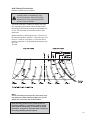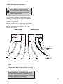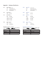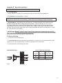
1
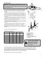
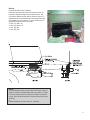
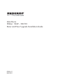
TM
John Deere
Walker MAV - 300/310
Rotor and Floor Upgrade Installation Guide
RD001-01
MAR 2011
ROTOR BLADE
A
IMPORTANT! The paddle blades, located on the balance rings
inside the chopper, must be installed in the direction shown (A).
The straight edge of the blade cuts the air while the paddle trails
behind & pushes the air.
1. The blades for your chopper must be installed as outlined.
Note: If blades are installed other than as directed, damage to
the chopper may result or performance may be significantly
reduced.
1) Always replace blades two pairs at a time, directly opposite
each other through the center of the rotor. This should maintain rotor
balance. Never replace only one blade for wear or breakage. You
do not need to replace the corresponding two pairs on the other end
of the rotor.
2) If a blade breaks and the chopper must be operated without a
replacement then the damaged blade and the one directly opposite it
must both be removed to maintain rotor balance.
3) Use only METRIC class 10.9 bolts (B) and class 10.9 DIN980V
steel lock nuts (F) on the chopper rotor.
4) Use a torque wrench to tighten all M12 nuts to the recommended 69 ft-lb.
5) Always check for adequate clearance between the installed
blades and the stationary knives. A minimum of 1/4” is required.
Check clearance of all blades, even those that are not replaced. Do
not operate the straw chopper unless this clearance is maintained for
all blades.
A
D
D
F
C
E
2. Assembly order for blade pairs (B to F).
E
B
MetricBoltTorqueTable
PropertyClass
NominalSize&
ThreadPitch
M6x1.00
M8x1.25
M10x1.50
M12x1.75
M14x2.00
M16x2.00
M18x2.50
M20x2.50
C
8.8
8.8
10.9
10.9
(Nm)
8
19
38
66
106
164
226
319
(FtͲLbs)
6
14
28
49
78
121
167
235
(Nm)
11
27
54
94
150
233
323
457
(FtͲLbs)
8
20
40
69
111
172
238
337
*Allvaluesfordry,yellowzincplatedhardware.
A - Blade direction
B - Hex cap screw
C - Washer
D - Blade, straight
E - Bushing, straight blade
F - Lock nut
CAUTION: Always use METRIC
class 10.9 bolts and class 10.9
DIN980V steel lock nuts when
installing blades. Allowable
torque range for blade mount
nuts is 69 ft-lb.
Torque values listed are for general use only, based on the strength of the bolt. DO NOT use these
values if a different torque value or tightening procedure is given for a specific application. For stainless steel fasteners or for nuts on U-bolts, see the tightening instruction for the specific application.
Tighten plastic insert or crimped steel type lock nuts by turning the nut to the dry torque shown in the
chart, unless different instructions are given for the specific application.
“Dry” means plain or zinc plated without any lubrication.
2
KIT CONTENTS
REF
1
2
3
4
4
5
5
6
6
7
8
9
9
10
ITEM NAME
ITEM DESCRIPTION
JD W_ROTOR ROTOR ASSY
FLR EXT
FLOOR EXTENSION
KB PLATE
KNIFE BAR PLATE
SHEAVE
SHEAVE 2B 9.4PD SK HS
SHEAVE
SHEAVE 2B 11.0PD SK HS
SHEAVE
SHEAVE 2B 8.6PD SK HS
SHEAVE
SHEAVE 2B 9.0PD SK HS
BUSHING
BUSHING SK 1.375ID
BUSHING
BUSHING SK 1.295ID
BELT
BELT 2B173 (2B178)
BELT
BELT B122
SHROUD
SHROUD LEFT
SHROUD
SHROUD RIGHT
BOX
BOX 25 x 14 x 10d
HARDWARE BAG JD MAV
OPTIONAL
FIN
FLR
KB
KB GUARD
CD163K
QTY
1
1
1
1
1
1
1
1/2
1
1
1
1
1
1
2
1
1
3
FIN, TAILBOARD 31L
FLOOR 1in SP
KNIFE BAR 1in SP
KNIFE BAR GUARD
SHROUD ALIGNMENT KIT
2
1
1
1
1
5
6
NOTE:
The drive update is for the 9500 and 9600 series combines
only. The 60 series combines come complete with a double
drive and do not require Redekop drive parts.
4
The tailboard fin is available to order for the JD 9600 series
combine.
6
7
8
9
3
Rotor (MAV - 300/310)
1. Remove the straw chopper from the combine.
(See JD User Manual, Pg 65-5)
2. Remove the drive pulley, the shaft speed sensor disk,
and both lock collars from the straw chopper shaft.
3. Remove both bearings from the rotor.
-Try to avoid damaging the bearings as new bearings are not included in your retrofit kit.
4. Remove drive end wall from the straw chopper to allow removal of the factory rotor.
5. Install the Redekop upgrade rotor into the chopper
housing making sure that the blades are oriented in the
position shown (A).
6. Reassemble straw chopper. If your chopper does
not have sliding tracks, fan shrouds should be installed
before mounting chopper.
Before tightening the bearing lock collars, align
the rotor so the rotor blades are centered between
the stationary blades. After tightening lock collars,
recheck each individual blade to ensure that there
is adequate clearance between it and the stationary
blades.
A
Floor Extension
1. Hold the floor extension in place against the end the
the chopper floor as shown (B). Adjust the position of the
extension so the residue, when coming off the chopper
floor, is angled to hit the top of the fins at the back of the
tailboard.
2. Corresponding holes may exist in the chopper side
walls that can be used to fasten the floor extension. If
holes do not exist they must be drilled.
3. Fasten the floor extension to the chopper side walls.
See hardware definitions (Appendix:1)
4 - Bolt, Flg M8 x 20
4 - Nut, Flg M8
4. Reinstall the straw chopper on the combine.
B
4
Tight Spaced Floor Upgrade &
Knife Bar (MAV - 310)
Disassemble factory chopper floor and replace with
floor upgrade (A). See illustrations for positioning.
Use factory hardware to bolt in place.
A
Bolt in upgraded knife bar (B). Place a washer
on the inside face of (C) (at the end of the knife bar)
and on the outside face of (C) before inserting bolt.
Mount the handle (D) on non-drive side. Be sure
to center stationary blades in the middle of the
floor slots. Adjust blade angle to suit your chopping
needs and tighten bolts to secure positioning. See
illustrations for positioning.
8 - Washer, Flat M12
4 - Bolt M12 x 40
C
B
Install the knife bar guard (E). Place the open side of
the channel toward the floor of the chopper.
4 - Bolt, Flg M8 x 20
4 - Nut, Flg M8
E
D
E
5
Shroud
For 9500 & 9600 series combines.
Place the shroud directly above the center of rotor, on
top of the chopper sliding track and bolt in place. Be
sure the fan blades are not able to strike the shroud. If
adjustments to the shrouds need to be made slide chopper forward to access shrouds. If your combine is not
equipped with a track see note below.
4 - Bolt, Flg M8 x 20
4 - Bolt, Flg M10 x 25
4 - Nut, Flg M8
2 - Nut, Flg M10
Secure with bolt.
A
NOTE:
If your 9500/9600 series combine does NOT have a track or
flange to mount the Redekop shrouds onto install 1.5” angle
iron to the inside wall of the combine and place the shroud
on top. Be sure the shroud sits 6” above the top of the rotor
shaft (A).
or
Contact Redekop to order mount kit - CD163K.
6
Shroud
For 7720 & 8820 series combines.
Place shroud directly above the center of rotor and bolt
to the inside face of the chopper housing.
4 - Bolt, Crg M8 x 20
4 - Nut, Flg M8
7
Stationary Knife Bar Reinforcment
For factory knife bars with straight stationary blades
only.
Note:
The parallel blade rotor design used with the
Redekop rotor results in higher forces acting on the
stationary knives. As a result, the center section of
the knife bar can twist, and the knives may eventually cut into the chopper floor. To prevent this possible damage, it is recommended that the knife bar
be reinforced as outlined in this section.
B
A
E
Remove the knife bar from the chopper by removing the
bolt at each end of the bar.
C
D
Position the knife bar as shown (A) with the open side of
the bar facing up. It is this open side that is reinforced.
F
Place the reinforcement bar on the knife bar as shown
(B). The reinforcement bar should rest on the stationary knives. Hold the reinforcement bar against the 3/8”
round rod already welded to the knife bar. Tack weld the
reinforcement to the round rod in three places. Clamp
the knife bar against each reinforcement tab and spot
weld at each of the three tabs.
G
The reinforcement bar should be securely welded to
the knife bar at both ends of the reinforcement bar (C),
at each of the three tabs (D), and 1.5 inch beads spaced
every 6 inches along the round 3/8” rod (E).
H
Rear Panel
Roll the chopper forward to verify if the rear panel (F)
must be modified to clear the newly mounted shrouds
(H). If the chopper does not move freely to the windrowing position cut sufficient material off the ends of the
panel (G).
G
8
Chopper Drive
For combines equipped with the factory single belt drive.
G
Remove the inside sheave on the combine chopper
drive tightener unit (A). Remove the tightener assembly
in order to remove the sheave. Replace with a 2B9.4
sheave and SK 1-3/8 bushing (B) and place in the same
location as the factory sheave. See Appendix: 2
**JD 9650 1 - Sheave, SK 2B11.0
1 - Bushing, SK 1.295
A
B
F
E
Install the factory speed sensor collar (C) over the lock
collar on the chopper shaft and mount the speed sensor
pickup (D) using the rotor bearing bolts. Plug in the wiring to the pickup.
A
Install the 2B8.6 sheave and SK 1-3/8 bushing (E) on
the straw chopper shaft. Do not tighten the bushing at
this time.
**JD 9650 1 - Sheave, SK 2B9.0
1 - Bushing, SK 1.375
C
Install the 2B173 belt (F) between sheaves. Align
sheaves for smooth belt operation and tighten bushings.
**JD 9650 1 - Belt, 2B178
D
Adjust belt tension using the spring tightener (G) unit on
the factory chopper drive. Adjust according to instructions provided in the combine operators manual.
Note:
Belt B122 included in your Redekop kit will
be required to drive the straw chopper when
the chopper is moved forward to the windrow
position.
**JD 9650 Belt B122 NOT included in kit.
9
9600 Tailboard Fin Alteration
Available for 9600 series combines.
Order and install the extra fin if your
spreading width is unsatisfactory using
the factory tailboard. Make the following
adjustments if an increased spread width
of 30 ft or more is desired.
The factory tailboard is modified to achieve the maximum spreading performance with the Redekop MAV
technology by rearranging existing fins and adding one
31” fin. See illustration for new hole locations & fin
placement.
Modify tailboard by relocating fins 2 & 4. Place fin 2 in
the outermost position, position 4. Drill hole at the front
of the fin. Place fin 4 in position 2. Drill holes where
needed. Install the 31” long Redekop fin between position 3 & 4.
JD 9600
Note:
Check all fasteners to ensure they have been properly tightened. When starting chopper, be sure all
people are clear of the rear of the combine.
Start threshing module in low speed & listen for
clearance problems. If a knocking noise is heard
stop machine immediately! Fix problem & repeat
procedure. Progress to full power when everything
is running smoothly at lower speeds.
10
9500 & CTS Tailboard Fin Alteration
Available for 9500 & CTS series combines.
Order and install the extra fins if your
spreading width is unsatisfactory using
the factory tailboard. Make the following
adjustments if an increased spread width
of 30 ft or more is desired.
The factory tailboard is modified to achieve the maximum spreading performance with the Redekop MAV
technology by rearranging existing fins and adding two
31” fins & two 13” fins. See illustration for new hole
locations & fin placement.
Drill new front holes for fin 2, Redekop 31” and Redekop
13”. Use existing rear holes for fin 2 and Redekop 31”.
Measure and drill rear hole on Redekop 13” fin with
reference to the 31” fin.
OLD PATTERN
NEW PATTERN
Note:
Check all fasteners to ensure they have been properly tightened. When starting chopper, be sure all
people are clear of the rear of the combine.
Start threshing module in low speed & listen for
clearance problems. If a knocking noise is heard
stop machine immediately! Fix problem & repeat
procedure. Progress to full power when everything
is running smoothly at lower speeds.
11
Appendix: 1 - Hardware Classification
B##
N##
P##
W##
Bolt - Imperial
B##M
Bolt - Metric
HEX
Bolt Hex Head
HEX
FLG
Bolt Hex Flange Head
FLG
Bolt Hex Flange Head
RH
Bolt Round Head, Carriage
RH
Bolt Round Head Carriage
CS
Bolt Countersunk
CS
Bolt Countersunk
Nut - Imperial
N##M
Bolt Hex Head
Nut - Metric
JAM
Nut, Jam
JAM
Nut, Jam
LOCK
Nut, Lock
LOCK
Nut, Lock
Pin - Imperial
P##M
Pin - Metric
ROLL
Pin, Roll
ROLL
COT
Pin, Cotter
COT
Pin, Cotter
HITCH
Pin, Hitch Clip
HITCH
Pin, Hitch Clip
LYNCH
Pin, Lynch
LYNCH
Pin, Lynch
CLEVIS
Pin, Clevis
CLEVIS
Pin, Clevis
SPIROL
Pin, Spirol
SPIROL
Pin, Spirol
Washer - Imperial
W##M
Pin, Roll
Washer - Metric
FLAT
Flat
FLAT
Flat
LOCK
Helical Lock
LOCK
Helical Lock
FEN
Fender Washer
FEN
Fender Washer
Description: BOLT HEX .5 X 1 GR5 UNC
Type = Hex
Imperial Spec = GR5 UNC
Diameter = 0.5 inch
Length = 1 inch
Description: BOLT HEX M8 X 40 C8.8
Type = Hex
Diameter = 8mm
Hardware Diameter
1/4in Hardware
5/16 Hardware
3/8 Hardware
1/2 Hardware
5/8 Hardware
Hardware Diameter
M6 Hardware
M8 Hardware
M10 Hardware
M12 Hardware
M16 Hardware
Wrench Size
7/16in
1/2in
9/16in
3/4in
15/16in
Wrench Size
10mm
13mm
15mm or 16mm
18mm or 19mm
24mm
Metric Spec = C8.8
Length = 40mm
Appendix: 2 - Taper Hub Installation
IMPORTANT: DO NOT USE LUBRICANTS IN THIS INSTALLATION
To Install Bushing:
1. Remove all paint, oil grease, etc. from tapered surface of bushing and bore of mating part.
2. See Standard mounting assembly - Figure 1.
NOTE: If bushing does not slide freely on shaft, wedge a screwdriver blade into the saw cut and the
flange OD to open the bore of the bushing. Caution: Excessive wedging will split the bushing.
3. Standard Mount – Slide bushing on shaft, flange first. If using the setscrew, snug it against the key.
Excessive Torque will cause mating part to be eccentric. Position mating part in place on bushing aligning drilled holes in mating part with tapped holes in bushing flange. Using lock washers, install
capscrews thru the mating hub and into the bushing flange. (Note: S bushings can only be Standard
Mounted. Be sure the three tapped holes in the mating hub do not align near the bushing saw cut. If they
do, rotate the bushing 60 degrees.).
4. Use A Torque Wrench. Tighten all capcrews evenly and progressively in rotation to the torque value
listed in the table. Excessive wrench torque, closing the gap between the bushing flange and mating
hub, or the use of lubricants will break the mating hub.
To Remove Bushing:
1. Loosen and remove all capscrews.
2. For Standard Mount, thread capscrews into tapped holes in mating part to jack against bushing flange.
Tighten bolts evenly and progressively in rotation to separate the two components.
3. Loosen setscrew to slide bushing from shaft.
Standard Mounting
Screw Tightening Information
Tapered
Bushing
Ft.-Lbs. To
Size & Thread
Apply With
of Capscrew Torque Wrench
SK
5/16 - 18
15
SF
3/8 - 16
30
Fig. 1
13
WARRANTY
Redekop Manufacturing Co., hereinafter referred to as
“Manufacturer”, warrants each new Redekop Upgrade
sold by the Manufacturer to be free from defects in material and workmanship, under normal use and service,
for a period of one (1) year after the date of delivery to
the original retail purchaser. The Manufacturer will, at its
option, replace or repair, at the Manufacturer’s factory,
or at a point designated by the Manufacturer, any part or
parts which shall appear to the satisfaction of the Manufacturer upon inspection at such point, to have been defective in material or workmanship. This Warranty does
not obligate the Manufacturer to bear any transportation
charges in connection with the replacement of defective
parts.
This Warranty shall not apply to any rotor which shall
have been installed or operated in a manner not recommended by the Manufacturer; nor to any rotor which
shall have been repaired, altered, neglected or used in
any way which, in the Manufacturer’s opinion, adversely
affects its performance; nor to any rotor in which parts
not manufactured or approved by the Manufacturer have
been used; nor to any accessories installed on the rotor
where the accessory manufacturer has its warranty; nor
to normal maintenance or replacement of normal service
items.
Manufacturer reserves the right to modify, alter, and improve any rotor or parts without incurring any obligation
to replace any rotor or parts previously sold with such
modified, altered or improved rotor or part.
THIS WARRANTY, AND THE MANUFACTURER’S OBLIGATION HEREUNDER, IS IN LIEU OF ALL OTHER
WARRANTIES, EXPRESSED, IMPLIED, OR OF FITNESS FOR A PARTICULAR PURPOSE, and all other
obligations or liabilities, including special or consequential damages or contingent liabilities arising out of the
failure of any rotor or part to operate properly. No person
is authorized to give any other warranty or to assume
any additional obligation on the Manufacturer’s behalf
unless made in writing and signed by an officer of the
Manufacturer.
This Warranty is effective only for the original purchaser.
Redekop Manufacturing Co.
Saskatoon, SK Canada
14