1
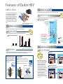
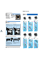
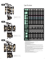
Warning
Ask a qualified installer or contractor to install this product. Do not try to install the product yourself.
Improper installation can result in water or refrigerant leakage, electrical shock, fire or explosion.
PCH0601
Use only those parts and accessories supplied or specified by Daikin. Ask a qualified installer or
contractor to install those parts and accessories. Use of unauthorized parts and accessories or
improper installation of parts and accessories can result in water or refrigerant leakage, electrical
shock, fire or explosion.
Read the User's Manual carefully before using this product. The User's Manual provides important
safety instructions and warnings. Be sure to follow these instructions and warnings.
For any inquiries, contact your local distributor.
HE A T R E CLA IM V E N T ILA T ION
Combined Air Conditioning and Ventilation
for E nergy E fficiency and Comfort
Cautions on product corrosion
1. Air conditioners should not be installed in areas where corrosive gases, such as acid gas or alkaline gas, are produced.
2. If the outdoor unit is to be installed close to the sea shore, direct exposure to the sea breeze should be avoided and choose an
outdoor unit with anti-corrosion treatment.
The air conditioners manufactured
by Daikin Industries have
received ISO 9001 certification for
quality assurance.
Certificate Number. JMI-0107
JQA-0495
JQA-1452
All Daikin Industries locations
and subsidiaries in Japan have
received environmental
management system standard
ISO 14001 certification.
Daikin Industries, Ltd.
Domestic Group
Certificate Number. EC99J2044
Dealer
About ISO 14001
ISO 14001 is the standard defined by the
International Organization for Standardization (ISO)
relating to environmental management systems.
Our group has been acknowledged by an
internationally accredited compliance organisation
as having an appropriate programme of
environmental protection procedures and activities
to meet the requirements of ISO 14001.
Head Office:
Umeda Center Bldg., 2-4-12, Nakazaki-Nishi,
Kita-ku, Osaka, 530-8323 Japan
Tokyo Office:
JR Shinagawa East Bldg., 2-18-1, Konan,
Minato-ku, Tokyo, 108-0075 Japan
http://www.daikin.com/global/
c All rights reserved
Printed in Japan 05/06/003 Y.K.
The specifications, designs, and information in this brochure are subject to change without notice.
Printed on 100% recycled paper with soy ink.
Daikin's HRV (Heat Reclaim Ventilation) recovers heat energy lost through ventilation
and holds down room temperature changes caused by ventilation, thereby maintaining a
comfortable and clean environment. This also curbs the load on the air conditioning
system and conserves energy.
In addition, the HRV is interlocked to Daikin's VRV system, SkyAir and other air
conditioning systems and automatically switches over ventilation mode, further increasing
the effects of energy conservation. HRV operation has been centralized on the air
conditioner remote controller allowing total control over air conditioning and ventilation
with a simple configuration.
V A M -G J S e r ie s R e le a s e d!
9 M o de ls t o C h o o s e F r o m !
Improved Enthalpy Efficiency
1
Higher External Static Pressure
2
1 For models: VAM150/250/350/650/800/1000/2000GJVE
2 For models: VAM150/350/500GJVE
Enhanced Energy Saving Functions
Daikin air conditioner
Indoor unit
• ON/OFF signal
• Cooling/Heating mode signal
• Set temperature signal
• Ventilation signal
• Humidifier ON/OFF signal
Interlocking
• Operating mode signal
• Filter cleaning signal
• Failure detection signal
HRV
LCD remote controller
for indoor unit
Model Lineup
Model Series
VAM-GJ
Air flow rate (m3/h)
150
250
350
500
650
800 1000 1500 2000
F e a ture s of Da ik in H R V
V A M -G J S e r ie s
Higher exter nal static pr essur e
2
External static pressure has been significantly increased by adopting a new type of fan.
Exhaust air
VAM650GJ
Return air
Improvements to the fan, including the use of multi-arc blades and optimized fan sizes, help boost efficiency.
Outdoor air
Comparison of external static pressure
(For ultra high operation)
Supply air
1
Enthalpy efficiency dr astically impr oved!
Introduction of ultra-thin film element significantly increases enthalpy efficiency!
1
Impr ov
ed!
Enthalpy efficiency improved
Adoption of the ultra-thin film element leads to highly improved enthalpy efficiency.
VAM-FA
Previous model
VAM-GJ
Model
GJ
64
64
GJ
62
61
GJ
60
58
58
56
External static pressure
increased by 71 Pa
(for 50 Hz operation)
61
FA
Thickness of
the partition sheet
150
650
1000
(Air flow type)
1 For models: VAM150/250/350/650/800/1000/2000GJVE
Ultra-thin film element
60
VAM350GJVE
300
50
30m
250
200
150
20m
150
Pipe
length
VAM350FAVE
100
10m
50
50Hz,220–240V
60Hz,220V
VAM-GJ Model
VAM-FA Previous
100
200
300
400
500
600
Air flow rate (m /h)
3
Ener gy conser vation and comfor table air space
•Decreases the moisture resistance of the partition sheets
drastically.
•Realizes more space for extra layers in the element, resulting
in increased effective area that supply and exhaust air can be
exposed to.
Thickness of
the partition sheet
Moisture absorption increased by approx. 10%!
Indoor
Outdoor
Molecule of water
Miscellaneous gas
CO2 molecule, etc.
Exhaust air
Exhaust air
Exhaust air
SA
SA
Precise, thin-film
material
RA
(unclean
indoor air)
Outdoor air
(fresh air)
No operation
Air conditioning sensible
heat load reduced by
appr ox.
Due to the thinner film…
High-humidity air
RA
(unclean
indoor air)
40m
Nighttime free cooling operation
Outdoor
Outdoor air
(fresh air)
70
2 For models: VAM150/350/50
Sheet structure
Indoor
80
FA
The partition sheet in the heat exchanger element has been significantly upgraded. It is approximately two-third
thinner than the conventional type, resulting in a great improvement in moisture absorption!
Moisture absorption is less effective
due to the thickness of the partition
sheets. It also limits the effective
area that supply and exhaust air can
be exposed to.
90 (%)
0
58
FA
Ultra-thin film element
Previous element (FA model)
External static pressure
increased by 80 Pa
(for 60 Hz operation)
(For ultra high cooling operation)
66
66
Cooling: Enthalpy efficiency (%)
Achieving higher enthalpy efficiency
1
Exchange efficiency
High external static
pressure is realized
even below the
rated air flow!
1 For models: VAM150/250/350/650/800/1000/2000GJVE
2 For models: VAM150/350/500GJVE
1
2
High external static pressure design adopting efficient fan performanceImpr ove
External static pressure (Pa)
1
This series provides higher enthalpy efficiency,
due to the greatly enhanced performance of the
new ultra-thin film element. Furthermore,
2
improved external static pressure offers more
flexibility for installation. Along with these three
improvements, Daikin’s exclusive function
—nighttime free cooling operation—contributes
to energy conservation and more comfortable
space.
Supply air
Low-humidity air
Moisture exchange efficiency is greatly improved by using optimized
thinner films and moisture-absorption materials in the element.
Furthermore, miscellaneous gas barrier properties are maintained by
decreasing the porosity in the moisture-absorption materials.
5%!
Nighttime free cooling operation is an
energy-conserving function that works at
night when air conditioners are off. By
ventilating rooms containing office
equipment that raises the room
temperature, nighttime free cooling
operation reduces the cooling load when
air conditioners are turned on in the
morning. It also alleviates feelings of
discomfort in the morning caused by heat
accumulated during the night.
•Nighttime free cooling operation only works to cool and
if connected to Building Multi or VRV systems.
•Nighttime free cooling operation is set to “off” in the
factory settings, so if you wish to use it, request your
dealer to turn it on.
Not operating
Indoor
unit
Generated
heat
Retained heat
Heat generated by computers etc., is retained
in the walls and ceiling.
Exhaust
heat
Indoor
unit
Unco
The air conditioning load is large so the temp
is not reduced quickly.
Nighttime free cooling operation
The indoor accumulated heat is discharged at night. This reduces the air cond
load the next day thereby increasing efficiency.
Cold air
Exhaust
heat
Generated
heat
Heat is discharged.
Indoor
unit
Indoor
unit
Exhaust
heat
Com
The load is small so the temperature is rapid
to a comfortable level.
*Interlocked operation with an air
3
Air Conditioning Load Reduced by Appr oximately 30%
1 . Approximately 20% by operating in total heat exchange mode
Auto-ventilation Mode Changeover Switching
(in comparison with normal ventilation fans)
2 . Another approximately 8% gained by auto-ventilation mode changeover switching
3 . Yet another approximately 2% by pre-cool, pre-heat control
Automatically switches the ventilation mode (Total Heat Exchange Mode/Bypass Mode) according to the operating
status of the air conditioner.
Total Heat Exchange Mode
• The above values may vary according to weather and other environmental conditions at the location of the machine's installation.
• The above values are based on the following conditions;
Application: Tokyo office building
Building form: 2 floors above ground, 6 floors underground, floor area 2,100 m2
Personnel density: 0.25 person/m2
Ventilation volume: 25 m3/h
Indoor air conditioning level: summer 25°C 50% RH, intermediate seasons 24°C 50% RH, winter 22°C 40% RH
Operating time: 2745 hours (9 hours per day, approx. 25 days per month)
Calculation method: simulation based on "MICRO-HASP/1982" of the Japan Building Mechanical and Electrical Engineers Association.
(Cooling operation in summer/Heating operation in winter)
Exhaust air
appr ox.
30%!
Return air
Air exhaust fan
Outdoor air intake
Interlocking
Annual air conditioning
load reduced by
Room temperature sensor
Heat exchange element
Air supply fan
Supply air
Outdoor air temperature sensor
The HRV is interlocked to Daikin's VRV system, SkyAir and other air
conditioning systems and automatically switches over ventilation mode, further
increasing the effects of energy conservation. HRV operation has been
centralized on the air conditioner remote controller allowing total control over air
conditioning and ventilation with a simple configuration.
Bypass Mode (“Intermediate” season)
Heat exchange element
Exhaust air
Return air
Air exhaust fan
Outdoor air intake
Daikin air conditioner
Indoor unit
• ON/OFF signal
• Cooling/Heating mode signal
• Set temperature signal
• Ventilation signal
• Humidifier ON/OFF signal
Air supply fan
Outdoor air temperature sensor
*
(Intermediate season)
Compact equipment
306 mm
* In case of VAM500GJVE
• Operating mode signal
• Filter cleaning signal
• Failure detection signal
LCD remote controller
for indoor unit
Cold climate compatible :
HRV
Pre-cool, Pre-heat Control
Reduces air conditioning load by not running the HRV while air is still clean soon after the air conditioner is
turned ON.
*Supply air
The air cannot be supplied
at the same temperature
as the outdoor air because
it is partly heat-exchanged.
With a height of just 306 mm, the unit easily fits in limited
spaces, such as above ceilings.
Interlocking
Indoor air temperature sensor
Standard operation at temperatures down to -15°C
The intermittent operation mode is activated when
outdoor temperature goes down to -10°C or below,
preventing freezing or condensation in the unit. Standard
models can now be used in cold climate regions.
50
40
50˚CDB
30
20
10
0
-10
-15˚CDB
-20
5
6
C e ntra liz e d C ontrol of
A ir C onditioning a nd V e ntila tion
The operation of the air conditioner using the remote controller is interlocked to the operation of
the HRV, greatly simplifying overall system operation. In addition, installation work associated
with the HRV remote controller is not necessary because operations for air conditioning and
ventilation are completely centralized on the air conditioner remote controller. Also, the use of
such a centralized remote controller allows the user to choose a wide range of control systems
that integrate air conditioning and ventilation. Furthermore, by using a variety of centralized
control equipment, the user can build a large, high-grade centralized control system.
Oper ations and Contr ol with the Air Conditioning Remote Contr oller
• Simultaneous ON/OFF of the HRV and indoor unit air conditioner
• Independent operation of the HRV
• Airflow rate switching (initial setting)
• Ventilation mode switching
• Self-diagnosis functions
• Filter sign display and reset
• Timer settings (simultaneous control with air conditioner)
• Pre-cool, pre-heat control settings (initial setting)
• Fresh-up mode switching (Selectable: supply rich mode, exhaust
rich mode; Initial setting)
Centr alized Contr ol System
By combining the (optional) centralized control equipment below, the user can achieve a wide range of
comprehensive centralized control systems for air conditioning and ventilation.
Centralized Controller
(DCS302CA61)
• One unit can operate and monitor up to 64 groups (128 units) of HRV
and air conditioner units individually or in batch.
• Allows the user to divide connected HRV or air conditioner units into
zones (up to 64) and control any or all of them.
• Two units of this controller can be linked, thereby allowing centralized
control of up to 128 groups (128 units).
• Centralized control from two places is possible using two units of this
controller.
• Ventilation volume and mode can be controlled for Heat Reclaim
Ventilation.
Unified ON/OFF Controller
(DCS301BA61)
• One unit can turn ON/OFF up to 16 groups (128 units) of HRV and air
conditioner units individually or in a batch.
• Lamps display operation and failure status of the connected HRV and
air conditioner units.
• Up to 8 units can be linked to allow centralized control of up to 128 units.
BRC1C62
A Var iety of Contr ol Systems That Can Be Contr olled
Using Only the Air Conditioner Remote Contr oller
Group Control
Up to 16
units
One air conditioner remote controller simultaneously controls up
to 16 air conditioner and HRV units.
2-Remote-Controller Control
Allows control of air conditioner and HRV units from two places by
connecting two air conditioner remote controllers. (Group control
possible)
Long-distance Remote Control
Operation control from afar, i.e., a distant control room, is possible
thanks to wiring of up to 500 m. (Group control and 2-remotecntroller control possible)
Control with 2 Remote Controllers
(for HRV and Air Conditioner)
System with dual use of the HRV remote controller and air
conditioner remote controller can be achieved. Changes in initial
setting functions are always possible. (Group control possible)
7
Schedule Timer
Air conditioner
Air conditioner
remote controller
Air conditioner
Air conditioner
remote controller (No. 2)
Air conditioner
remote controller (No. 1)
Air conditioner
HRV
Up to 500 m
Group
control
possible
Up to 500 m
Group
control
possible
HRV
HRV
Air conditioner
remote controller
2-remote-controller control possible
Up to 500 m
• One unit can control the operation of up to 128 HRV and air conditioner
units on a weekly schedule.
• Can set two ON/OFF operations per day for a period of one week.
Up to 500 m
Air conditioner
(DST301BA61)
Group
control
possible
Number of units that can
be connected per system
Centralized controller
Unified ON/OFF controller
Schedule timer
2 units
8 units
1 unit
HRV
Air conditioner
remote controller
HRV remote controller
8
Image of group
control system
V a r io u s C o ntr o l S y s te m s A c c o r ding to
A pplic a tio ns a nd C onditio ns
Combined
system
Independent
system
Major HRV Contr ol Systems
Necessary
System Characteristics Accessories
9
Main
remote controller
HRV
• Operation is possible
using 2 HRV remote
controllers.
Main
remote controller
• Multiple HRV units can
be simultaneously
controlled in batch.
HRV remote
controller
• HRV remote controller
does not have to be used.
Indoor unit
• Up to 16 VRV indoor
units or HRV units can
be connected and
controlled in batch, with
interlocked operation of
HRVs and air
conditioners by using
the air conditioner
remote controller.
HRV
Air conditioner
remote controller
Group 1
Indoor
unit
Air conditioner
remote controller
Group 1
Indoor
unit
Air conditioner
remote controller
HRV
Group 2
Indoor
unit
Air conditioner
remote controller
Group 2
Indoor
unit
Air conditioner
remote controller
Wiring adaptor
for electrical
appendices
VRV remote
controller/
SkyAir
remote
controller
HRV
• Can control interlocked
operation of multiple
groups of VRV or SkyAir
indoor units.
• When one of the multiple
groups operates, HRVs
are interlocked and
operates simultaneously.
Batch/Individual Control System
HRV remote controller
ON/OFF
controller
HRV
Indoor
unit
Indoor
unit
• Up to 128 VRV, SkyAir and
HRV units can be centrally
controlled over a centralized
line (Special adaptor is required to
connect the SkyAir to the centralized line.)
HRV LCD
remote
controller
Air conditioner
remote controller
HRV
Indoor
unit
Indoor
unit
HRV LCD
remote
controller
Air conditioner
remote controller
Indoor unit
• HRV remote controller can
set the individual operation
of each HRV unit.
• Control system can be
expanded depending on its
purposes by combining a
variety of centralized control
equipment.
(Special adaptor is required to connect the
SkyAir to the centralized line.)
• Control is possible in three
different patterns:
Individual/Batch/Zone.
HRV
Air conditioner
remote controller
Indoor unit
• Can independently operate
multiple HRV units.
Indoor unit
HRV
HRV
Air conditioner
remote controller
• System without air conditioner
and HRV remote controllers
can be constructed.
Can connect to
multiple HRV units
• Control system can be
expanded depending on its
purposes by combining a
variety of centralized control
equipment.
No-voltage a-contact signal
• Simultaneous operation of
HRVs and air conditioners is
possible using the air
conditioner remote controller.
Adaptor
Air conditioner
Necessary
Accessories
Unified ON/OFF
controller, VRV remote
controller, SkyAir
remote controller
When necessary,
centralized controller,
schedule timer, HRV
remote controller, and
SkyAir connection
adaptor
• Centralized controller has
setting and monitoring
functions equivalent to those
of a remote controller and can
centrally control up to 128
VRV, SkyAir and HRV units.
Indoor unit
Air conditioner
remote controller
VRV remote
controller/
SkyAir
remote
controller
System Characteristics
Centralized
controller
Zone Control System
HRV remote
controller
Air Conditioning Interlocked Centralized Control System
• Independent operation
of HRV is possible.
HRV
System Construction
Combination with
Other Types of
Air Conditioners
Independent
Operation
Simultaneous Operation
of Multiple Units
Standard System
Multiple groups Interlocked
Operation System
Air Conditioning Interlocked Control (VRV, SkyAir) System
Independent Operation System
System Construction
HRV
Combined
individual
system
HRV
Connecting line
can be extended
up to 50 m.
• Use of the HRV remote
controller enables to change
settings or operate HRVs
independently.
Unified ON/OFF
controller, VRV remote
controller, SkyAir
remote controller
When necessary,
centralized controller,
schedule timer, HRV
remote controller, and
SkyAir connection
adaptor
Connection adaptor
(No-voltage a-contact
signal)
10
M ode l L ine U p
Simple Design and Construction
The unit can be
installed upside down
in accordance with
the conditions of the
location.
VAM-GJ VE Ser ies
Switch box
Access door
HRV
HRV
Maintenance cover
VAM150GJVE
Fresh-up Operation
lpy
Normal
ventilation fan
Air exhaust
HRV
Air supply
Sick room
Air supply
Floor area
exc
ha n
fficie
fficie
ncy
ncy
fficie
VAM250GJVE
80
ncy
(hea
ting
60
ling
)
20m
15m
High
150
10m
100
5m
50
0
100
Pipe
length
Low
50
100
150
200
Air flow rate
250
Enthalpy ex
change
250
Ultra-High
200
70
efficiency
(heating)
efficiency (c
150
Pipe
length
150
40m
30m
100
50
20m
Low
10m
0
50
3
(m /h)
100
150
200
250
200
0
60
150
Pipe
length
High
100
3
40m
20m
150
300
350
Air flow rate (m /h)
70
UltraHigh
250
50
80
50
30m
300
60
ooling)
High
VAM500GJVE
10m
Low
100
VAM500GJVE
erature
excha
nge e
alpy
fficien
exch
cy
ange
efficie
ncy (h
eatin
Entha
g)
lpy ex
chang
e effic
iency
(cooli
ng)
Enth
400
No dust is blown out.
W ith C om pe titors ' P roduc ts
W ith the H R V
When conventional total heat exchange units, which
are independently operated using a dedicated remote
controller, are directly connected by a duct, there is a
possibility of dust falling from the air filter of the indoor
unit when the air conditioner is OFF.
When the HRV is operating independently, the fan in a
interlocked indoor unit continues turning, so dust does
not fall from the air filter.
350
External static pressure (Pa)
Blowing mode
300
200
300
400
500
600
Air flow rate (m /h)
3
200
150
0
500
70
450
60
50m
40m
30m
20m
Low
100
10m
200
300
400
500
600
700
50Hz,220–240V
60Hz,220V
Exchange efficiency
90 (%)
550
80
High
100
A sign is displayed on the remote controller when the air filter needs cleaning.
90 (%)
200
Pipe
length
Ultra-High
VAM800GJVE
50Hz,220–240V
60Hz,220V
50
250
50
VAM650GJVE
Exchange efficiency
Temp
11
exchange
80
ncy
90 (%)
ex. Hospital
50Hz,220–240V
60Hz,220V
Dust
Enthalpy
300
Ultra-High
200
Preventing Dust from Falling with Directly Mounted Ducts
OFF
re exchan
ge efficie
70
)
(coo
Tempera
tu
Exchange efficiency
VAM350GJVE
Tempera
ture exch
ange effic
Enth
iency
alpy
e xc h
ange
effic
ienc
Enth
y (he
alpy
ating
exch
)
ange
effic
ienc
y (co
oling
)
Exchange efficiency
90 (%)
VAM150GJVE
chan
ge e
ge e
ge e
250
Portion of
exhaust
operation
ex. Office
re ex
External static pressure (Pa)
HRV
Raising exhaust air decreases room pressure to prevent
the leaking of odors or floating bacteria into other rooms.
External static pressure (Pa)
Portion of fresh-up
operation
Air exhaust
Enth
a
E x ha us t ric h m ode :
Raising the air supply maintains proper room pressure to
prevent back-flow of toilet/kitchen odors or moisture inflow.
eratu
alpy
exch
an
The user can select between two fresh-up modes using the remote controller.
S upply ric h m ode :
Tem
p
Enth
50Hz,220–240V
60Hz,220V
50Hz,220–240V
60Hz,220V
Exchange efficiency
90(%)
VAM350GJVE
External static pressure (Pa)
50Hz,220–240V
60Hz,220V
External static pressure (Pa)
Clean
VAM250GJVE
ture exch
80
ange effic
iency
Enthalp
y exchan
ge effici
ency (h
eating) 70
Enthalp
y exchan
60
ge effici
ency (co
oling)
50
Ultra-High
60m
350
300
High
50m
250
40m
200
30m
150
100
20m
Low
50
0
100
200
300
400
80 (%)
VAM650GJVE
Tempera
400
Exchange efficiency
500
600
10m
200
Pipe
900 length
700 800
Air flow rate (m /h)
3
VAM800GJVE
Enth Tempe
alpy rature
exch
e
ange xchange e
fficie
effic
ncy
ienc
Enth
y (he
alpy
ating
exch
)
ang
e eff
icien
cy (c
ooli
ng)
Ultra-High
500
External static pressure (Pa)
With only one 450-mm
square inspection
aperture, maintenance
and heat exchange
element replacement can
be performed with ease.
400
70
60
50
High
300
250
Pipe
length
100m
80m
200
100
60m
Low
40m
20m
0
200
400
600
800
1000
Air flow rate (m /h)
3
12
VAM-GJ VE Ser ies
Dimensions
VAM350GJVE
VAM500GJVE
Maintenance space for the heat exchange
elements, the air filters and fans
Maintenance space for the heat exchange
elements, the air filters and fans
cien
cy (
coo
300
70
)
60
250
Pipe
length
ling
)
Ultra-High
100m
80m
200
High
60m
40m
Low
100
500
Ent
halp
400
200
400
600
800
cha
ang
nge
e ef
e ef
300
fici
ficie
ncy
effi
cien
c
enc
y
(hea
ting
)
60
ool
in
g)
50
200
High
Low
0
1000 1200
Air flow rate (m /h)
500
3
1000
1500
alpy
70
Ultra-High
100
Enth
500
Enth
alpy
exch
ange
exch
ange
400
effic
eatin
g
effic
ienc
)
132
oling
)
823
Damper plate
(Maintenance cover)
(Control box)
132
50
High
0
2000
2500
Air flow rate (m /h)
500
1000
1500
3
2000
2500
Air flow rate (m /h)
132
879
150~250
600~
20
123
(Maintenance cover)
(Control box)
84
132
Air filters
EA
183
Exhaust air fan
High efficiency filter
(Optional accessory)
879
84
Air filters
Heat exchange elements
Remark)
1. Be sure to provide the inspection hole (450X450 mm) to inspect the air filters, the exchange elements
and fans.
2. It is possible to install the high efficiency filter on the SA face side of heat exchange element.
OA
137
416
823
Damper plate
High efficiency filter
(Optional accessory)
Heat exchange elements
Low
183
Exhaust air fan
200
100
247
137
RA
60
y (co
EA
132
850
20
123
850
416
RA
68
600~
247
800
70
efficie
ncy (h
Ultra-High
300
80
ienc
y
800
ange
150~250
68
VAM1500GJVE
exch
416
ture
123
247
ang
y (c
20m
0
y ex
exch
xch
pera
80
SA
247
alpy
re e
OA
20
effi
ating
Enth
atu
Supply air fan
197
400
ge
ienc
y (he
600
SA
132
Maintenance cover
213
han
effic
per
123
306
183
137
exc
nge
80
ncy
Tem
VAM2000GJVE
Tem
Exchange efficiency
90 (%)
Maintenance cover
Supply air fan
Ceiling hook
4-12X40 oval hole
Inspection hole
450
20
py
exch
a
efficie
50Hz,220–240V
60Hz,220V
Control box
200
External static pressure (Pa)
500
VAM1000GJVE
hange
306
183
146
hal
re exc
VAM2000GJVE
Exchange efficiency
90 (%)
700
External static pressure (Pa)
eratu
alpy
Ent
Exchange efficiency
90 (%)
Temp
Enth
50Hz,220–240V
60Hz,220V
450
137
50Hz,220–240V
60Hz,220V
VAM1500GJVE
External static pressure (Pa)
VAM1000GJVE
Ceiling hook
4-12X40 oval hole
Inspection hole
416
Control box
Remark)
1. Be sure to provide the inspection hole (450X450 mm) to inspect the air filters, the exchange elements
and fans.
2. It is possible to install the high efficiency filter on the SA face side of heat exchange element.
3
Dimensions
OA: Fresh air from outdoors (Outdoor air)
EA: Exhaust air to outdoors
VAM650GJVE
Heat exchange elements
145
Exhaust air fan
Air filters
Heat exchange elements
158
High efficiency filter
(Optional accessory)
810
149
139
(Maintenance cover)
(Control box)
137
132
Air filters
Remark)
1. Be sure to provide the inspection hole (450X450 mm) to inspect the air filters, the exchange elements
and fans.
2. It is possible to install the high efficiency filter on the SA face side of heat exchange element.
Heat exchange elements
High efficiency filter
(Optional accessory)
973
600~
163
20
163
153
EA
431
248
Damper plate
(Maintenance cover)
1034
153
OA
20
153
150~250
248
832
193
431
422
Exhaust air fan
RA
153
162
EA
248
897
SA
882
248
Damper plate
68
20
150~250
600~
RA
149
OA
20
754
EA
139
Ceiling hook
4-12X40 oval hole
Supply air fan
Exhaust air fan
235
High efficiency filter
(Optional accessory)
(Control box)
137
89
1110
Air filters
Remark)
1. Be sure to provide the inspection hole (450X450 mm) to inspect the air filters, the exchange elements
and fans.
2. It is possible to install the high efficiency filter on the SA face side of heat exchange element.
89
246
263
(Maintenance cover)
(Control box)
132
SA
OA
832
126
20
Damper plate
146
810
109
Supply air fan
387
235
Maintenance cover
250
High efficiency filter
(Optional accessory)
121
450
Ceiling hook
4-12X40 oval hole
121
275
601
551
275
RA
158
109
Maintenance cover
196
20
Exhaust air fan
EA
Remark)
1. Be sure to provide the inspection hole (450X450 mm) to inspect the air filters, the exchange elements
and fans.
2. It is possible to install the high efficiency filter on the SA face side of heat exchange element.
13
600~
150~250
SA
150
150
754
97
(Maintenance cover)
(Control box)
145
OA
338
193
Supply air fan
150
126
20
Damper plate
278
158
200
109
126
RA
121
275
601
150
551
275
SA
121
109
126
Supply air fan
Inspection hole
Inspection hole
450
Maintenance cover
68
600~
150~250
Ceiling hook
4-12X40 oval hole
68
278
158
Maintenance cover
450
Control box
Control box
Ceiling hook
4-12X40 oval hole
Inspection hole
450
422
Control box
Inspection hole
Maintenance space for the heat exchange
elements, the air filters and fans
Maintenance space for the heat exchange
elements, the air filters and fans
20
Control box
Maintenance space for the heat exchange
elements, the air filters and fans
162
Maintenance space for the heat exchange
elements, the air filters and fans
VAM800GJVE
882
VAM250GJVE
68
VAM150GJVE
200
SA: Supply air to room
RA: Return air from room
Heat exchange elements
Air filters
Remark)
1. Be sure to provide the inspection hole (450X450 mm) to inspect the air filters, the exchange elements
and fans.
2. It is possible to install the high efficiency filter on the SA face side of heat exchange element.
14
Maintenance space for the heat exchange
elements, the air filters and fans
Control box
VAM1000GJVE
Ceiling hook
4-12X40 oval hole
Supply air fan
163
20
68
150~250
600~
450
387
235
S pe c ific a tions
Inspection hole
Maintenance cover
153
439
153
OA
SA
1264
EA
439
163
20
153
1034
Damper plate
(Maintenance cover)
235
Exhaust air fan
High efficiency filter
(Optional accessory)
(Control box)
1110
89
Remark)
1. Be sure to provide the inspection hole (450X450 mm) to inspect the air filters, the
exchange elements and fans.
2. It is possible to install the high efficiency filter on the SA face side of heat exchange
element.
246
263
89
Heat exchange elements
VAM1500GJVE
Sound Level
dB(A)
[50Hz/60Hz]
Inspection hole
450
Maintenance cover
200~300
Ceiling hook
4-12X40 oval hole
Supply air fan
214
95
(Maintenance cover)
254
1110
(Control box)
214
Air Flow Rate (m3/h)
[50Hz/60Hz]
Remark)
1. Be sure to provide the inspection hole (450X450 mm) to inspect the air filters, the
exchange elements and fans.
2. It is possible to install the high efficiency filter on the SA face side of heat exchange
element.
Maintenance space for the heat exchange
elements, the air filters and fans
Inspection hole
200~300
650~
785
450
Ceiling hook
4-12X40 oval hole
Maintenance cover
Supply air fan
546
214
95
214
OA
501
1260
499
1214
499
SA
501
EA
546
160
214
RA
Damper plate
(Maintenance cover)
254
1034
Exhaust air fan
High efficiency filter
(Optional accessory) Heat exchange elements
1110
254 130
330
350
395
130
(Control box)
15
Air filters
75/75
72/72
78/78
72/72
77/77
79/79
75/75
79/79
74/74
75/75
72/72
78/78
72/72
77/77
Low
84/85
79/79
82/82
80/80.5
77/77.5
74/74.5
80.5/81
75.5/76
79/81
Ultra-High
72/72
71/71
70/70
67/67
67.5/67.5
65/65
70/70
65/65
72/72
High
72/72
71/71
70/70
67/67
67.5/67.5
65/65
70/70
65/65
72/72
Low
76/76.5
74/74
77/77
74/74.5
71.5/72
67.5/68
72.5/73
67/67.5
75/76
Ultra-High
66/66
63/63
66/66
55/55
61/61
61/61
64/64
61/61
62/62
High
66/66
63/63
66/66
55/55
61/61
61/61
64/64
61/61
62/62
Low
70/70.5
66/66
70/70
59/59.5
64/64.5
64/64.5
68.5/69
64/64.5
66/67
Ultra-High 27-28.5/28.5
27-29/29
31.5-33/33
33-35.5/34
34-36/36
High
26-27.5/27.5
26-27.5/28
30-31.5/30
31.5-34/32
33-34.5/34
Low
20.5-21.5/21
21-22/21
23-25/23
25-28.5/24
27.5-29.5/28
35-37.5/34
35-37.5/34.5
35-37.5/36
36-39/39
Ultra-High 28.5-29.5/29.5 28.5-30.5/30.5 33-34.5/34.5 34.5-36/35.5 35-37.5/37.5
40.5-42/41
40.5-42.5/40.5
41-43/42.5
43-45.5/44
Fan
External Static
Pressure (Pa)
[50Hz/60Hz]
160
214
39-40.5/39.5 39.5-41.5/39.5 39.5-41.5/41.5 41.5-43.5/42
38.5-40/39
38.5-40.5/38.5 39.5-41/41.5
37-39.5/37.5 37.5-39.5/37.5 37.5-39.5/39.5
39-43/40
High
27.5-28.5/28.5 27.5-29/29.5 31.5-33/31.5 33-34.5/33.5 33-35.5/35.5
Low
22.5-23.5/22 22.5-23/22.5 24.5-26.5/24.5 25.5-28.5/25.5 27.5-30.5/29.5 36-38.5/35.5 36-38.5/35.5 36.5-38/37.5 37.5-39.5/41
40.5-45/42
Galvanized steel plate
Self-extinguishable polyurethane foam
mm
278X 810X 551
306X 879X 800
338X 973X 832
kg
24
32
45
387X 1,111X 832 387X 1,111X 1,214 785X 1,619X 832 785X 1,619X 1,214
55
67
129
157
Air to air cross flow total heat (Sensible heat + latent heat) exchange
Specially processed nonflammable paper
Multidirectional fibrous fleeces
Type
Heat exchange elements
254 130
Air filters
Control box
74/74
High
Air Filter
Sirroco fan
Ultra-High
150/150
250/250
350/350
500/500
650/650
800/800
1,000/1,000
1,500/1,500
2,000/2,000
High
150/150
250/250
350/350
500/500
650/650
800/800
1,000/1,000
1,500/1,500
2,000/2,000
Low
100/95
155/155
230/230
320/295
500/470
700/670
860/840
1,320/1,260
1,720/1,580
Ultra-High
120/154
70/96
169/222
105/150
85/125
133/170
168/192
112/150
116/140
High
106/131
54/65
141/145
66/52
53/67
92/85
110/86
73/72
58/32
Low
56/60
24/20
67/30
32/18
35/38
72/61
85/60
56/50
Motor Output
kW
Connection Duct Diameter
mm
Unit ambient condition
VAM2000GJVE
79/79
Heat Exchange Element Material
160
Exhaust air fan
High efficiency filter
(Optional accessory)
75/75
Heat Exchange System
330
350
395
130
Weight
EA
310
1034
Damper plate
Bypass
Mode
Dimensions (HX WX D)
OA
20
160
Heat
Exchange
Mode
79/79
Insulation Material
878
308
310
832
546
214
RA
308
SA
For Cooling
Ultra-High
Casing
546
20
650~
785
214
Enthalpy
Exchange
Efficiency (%)
[50Hz/60Hz]
For Heating
Air filters
Maintenance space for the heat exchange
elements, the air filters and fans
Control box
VE: 1 phase, 220-240V/ 220V,50Hz/ 60Hz
Temp. Exchange
Efficiency (%)
[50Hz/60Hz]
153
RA
VAM150GJVE VAM250GJVE VAM350GJVE VAM500GJVE VAM650GJVE VAM800GJVE VAM1000GJVE VAM1500GJVE VAM2000GJVE
Power Supply
622
1214
622
Models
0.030X 2
100
0.090X 2
150
0.140X 2
200
0.280X 2
250
45/45
0.280X 4
350
-15°C ~ +50°CDB, 80%RH or less
Note: 1. Sound level is measured at 1.5m below the center of the body.
2. Air flow rate can be changed over to Low mode or High mode.
3. Sound level is measured in an anechoic chamber.
Sound level generally become greater than this value depending on the operating conditions, reflected sound, and peripheral noise.
4. The sound level at the air discharge port is about 8 dB higher than the unit's sound level.
5. The specifications, designs and information given here are subject to change without notice.
6. Temperature Exchange Efficiency is the mean value between cooling and heating.
7. Efficiency is measured under the following conditions:
Ratio of rated external static pressure has been maintained as follows; outdoor side to indoor side = 7 to 1.
8. In conformance with JIS standards (JIS B 8628), operating sound level is based on the value when one unit is operated, with the value converted for an anechoic chamber. This is
transmission sound from the main unit, and does not include sound from the discharge grille. Thus it is normal for the sound to be louder than the indicated value when the unit is
actually installed.
9. Sound level from the discharge port causes the value to be approximately 8 dB (models with the air flow rate of less than 150 to 500 m3/h) to approximately 11 dB (models with the air
flow rate of 650 m3/h or more) greater than the indicated value. Furthermore, fan rotation and noise from the discharge grille may increase depending on the on-site duct resistance
conditions. Please consider noise countermeasures when installing the unit.
10. With large models in particular (1500 and 2000 m3/h models), if the supply air (SA) grille is installed near the main unit, the noise of the main unit may be heard from the discharge
grille via the duct, and this will result in a marked increase in noise. In such cases, if peripheral effects are included (such as reverberation of the floor and walls, combination with
other equipment, and background noise), sound level may be as much as 15 dB higher than the indicated value. When installing a large model, please provide as much separation as
possible between the main unit and the discharge grille. If the equipment and discharge grille are near each other, please consider countermeasures such as the following:
•Use a sound-muffling box, flexible duct and sound-muffling air supply/discharge grilles
•Decentralized installation of discharge grilles
11. When installing in a location with particularly low background noise such as a classroom, please consider the following measures to avoid transmission sound from the main unit:
•Use of ceiling materials with high sound insulating properties (high transmission loss)
•Methods of blocking sound transmission, for example, by adding sound insulating materials around the bottom of the sound source.
Alternatively, consider supplementary methods such as installing the equipment in a different location (corridor, etc.)
Remark)
1. Be sure to provide the inspection hole (450X450 mm) to inspect the air filters, the
exchange elements and fans.
2. It is possible to install the high efficiency filter on the SA face side of heat exchange
element.
16
O ption
Installation of Optional Pr oducts (For VAM150GJVE. VAM250GJVE. VAM350GJVE. VAM500GJVE. VAM650GJVE. VAM800GJVE.
VAM1000GJVE. VAM1500GJVE. VAM2000GJVE.)
Air suction/discharge grille (Field supply)
PC board adaptor for heater control kit
Flexible duct
(Option)
RA
When the installation of an electric heater is required in a cold region, this adaptor with an internal timer function eliminates the
complicated timer connecting work that was necessary with conventional heaters.
High efficient filter
(Option)
SA
Indoor
Round hood
(Field supply)
Branch duct
(Field supply)
SA
Controlling device
PC Board Adaptor
EA
Temperature thermo. (Field supply)
(OFF when the temperature is at or more than 5°C)
Outdoor
EA
Heater
control kit
(Field supply)
OA
Temperature thermo.
(Field supply)
(ON when the temperature
is at or below -10°C)
Power supply (Field supply)
Relay box
Notes when installing
Examine fully an installation place and
specification for using the electric heater based on
the standard and regulation of each country.
Supply the electric heater and safety production
devices such as a relay and a thermostat, etc of
which qualities satisfy the standerd and regulation
of each country at site.
Use a non-inflammable connecting duct to the
electric heater. Be sure to allow 2m or more
between the electric heater and HRV for safty.
For the HRV units, use a different power supply
from that of the electric heater and install a circuit
breaker for each.
BRC301B61
DCS302CA61
DCS301BA61
DST301BA61
KRP2A61
Type
FXC-L
FXF-L
For wiring (indoor unit of VRV) FXCQ-M FXFQ-M
Installation box for adaptor PCB
BRP4A50
OA
Applicable model
Member
HRV remote controller
Centralized Central remote controller
controlling Unified ON/OFF controller
device
Schedule timer
Wiring adaptor for electrical
appendices
For humidifier
Installation box for adaptor PCB
For heater control kit
HRV
Silencer (Option)
Thermal insulation material (Field supply)
Option List
RA
SA
Duct
(Field supply)
(BRP4A50)
KRP1B61 KRP1B59
Note 2, 3 Note 2, 3
KRP1B96 KRP1D98
Note: 1. Installation box is necessary for each adaptor marked .
2. Up to 2 adaptors can be fixed for each installation box.
3. Only one installation box can be installed for each indoor unit.
KRP50-2
KRP50-2A90 (Mounted electric component assy of HRV)
BRP4A50
FXL-L
FXD-P
FXK-L FXD-N FXS-L FXM-L FXH-L
FXA-L
FXLQ-MA
FXYB-K
FXYD-KA
FXKQ-MA FXDQ-P FXSQ-M FXMQ-MA FXHQ-MA FXAQ-MA
FXN-L FXUQ-MA
FXNQ-MA
FXDQ-NA
KRP1B61 KRP1B56
KRP1B61
KRP1B3
—
KRP1B61
—
Note 4, 6 Note 5
Note 3
Note 2, 3
Note 5
—
—
—
—
KRP1B97
KRP1B101 KRP4A91
KRP1C93 KRP4A93
KRP1B100
4. Up to 2 installation boxes can be installed for each indoor unit.
5. Installation box is necessary for second adaptor.
6. Installation box is necessary for each adaptor.
Applicable model VAM150GJVE VAM250GJVE VAM350GJVE VAM500GJVE VAM650GJVE VAM800GJVE VAM1000GJVE VAM1500GJVE VAM2000GJVE
—
KDDM24B50
KDDM24B100
KDDM24A100X 2
Silencer
Nominal pipe diameter (mm)
—
200
250
High efficiency filter
KAF242G25M
KAF242G50M
KAF242G65M KAF242G80M KAF242G100M KAF242G80MX 2 KAF242G100MX2
Air filter for replacement
KAF241G25M
KAF241G50M
KAF241G65M KAF241G80M KAF241G100M KAF241G80MX 2 KAF241G100MX2
Flexible duct (1m)
K-FDS101C
K-FDS151C
K-FDS201C
K-FDS251C
Flexible duct (2m)
K-FDS102C
K-FDS152C
K-FDS202C
K-FDS252C
—
YDFA25A1
Duct adaptor
Nominal pipe diameter (mm)
—
250
Additional
function
Member
HRV Remote Controller
Silencer
17
Centralized controller
Unified ON/OFF controller
Flexible duct
(Noise suppression type)
Schedule timer
Duct adaptor
18