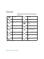
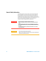
1
Agilent
U8001A/U8002A
Single Output
DC Power Supplies
User’s and Service Guide
Agilent Technologies
Notices
© Agilent Technologies, Inc. 2008–2013
Warranty
No part of this manual may be reproduced in
any form or by any means (including electronic storage and retrieval or translation
into a foreign language) without prior agreement and written consent from Agilent
Technologies, Inc. as governed by United
States and international copyright laws.
The material contained in this document is provided “as is,” and is subject to being changed, without notice,
in future editions. Further, to the maximum extent permitted by applicable
law, Agilent disclaims all warranties,
either express or implied, with regard
to this manual and any information
contained herein, including but not
limited to the implied warranties of
merchantability and fitness for a particular purpose. Agilent shall not be
liable for errors or for incidental or
consequential damages in connection with the furnishing, use, or performance of this document or of any
information contained herein. Should
Agilent and the user have a separate
written agreement with warranty
terms covering the material in this
document that conflict with these
terms, the warranty terms in the separate agreement shall control.
Manual Part Number
U8001-90001
Edition
Fifth Edition, July 12, 2013
Printed in Malaysia
Agilent Technologies, Inc.
3501 Stevens Creek Blvd.
Santa Clara, CA 95052 USA
Microsoft ® is a U.S. registered trademark
of Microsoft Corporation.
Safety Notices
Technology Licenses
The hardware and/or software described in
this document are furnished under a license
and may be used or copied only in accordance with the terms of such license.
Restricted Rights Legend
U.S. Government Restricted Rights. Software and technical data rights granted to
the federal government include only those
rights customarily provided to end user customers. Agilent provides this customary
commercial license in Software and technical data pursuant to FAR 12.211 (Technical
Data) and 12.212 (Computer Software) and,
for the Department of Defense, DFARS
252.227-7015 (Technical Data - Commercial
Items) and DFARS 227.7202-3 (Rights in
Commercial Computer Software or Computer Software Documentation).
II
CAUTION
A CAUTION notice denotes a hazard. It calls attention to an operating procedure, practice, or the like
that, if not correctly performed or
adhered to, could result in damage
to the product or loss of important
data. Do not proceed beyond a
CAUTION notice until the indicated
conditions are fully understood and
met.
WA R N I N G
A WARNING notice denotes a
hazard. It calls attention to an
operating procedure, practice, or
the like that, if not correctly performed or adhered to, could result
in personal injury or death. Do not
proceed beyond a WARNING
notice until the indicated conditions are fully understood and
met.
U8001A/U8002A User’s and Service Guide
Safety Symbols
The following symbols on the instrument and in the documentation
indicate precautions which must be taken to maintain safe operation of
the instrument.
Direct current
Off (supply)
Alternating current
On (supply)
Both direct and alternating
current
Equipment protected throughout
by double insulation or reinforced
insulation.
Three-phase alternating current
Caution, risk of electric shock.
Earth (ground) terminal
Caution, risk of danger (refer to
this manual for specific Warning
or Caution information.
Protective conductor terminal
Caution, hot surface.
Frame or chassis terminal
Out position of a bi-stable push
control.
Equipotentiality
In position of a bi-stable push
control.
U8001A/U8002A User’s and Service Guide
III
General Safety Information
The following general safety precautions must be observed during all
phases of operation, service and repair of this instrument. Failure to
comply with these precautions or specific warnings elsewhere in this
manual violates safety standards of design, manufacture and intended use
of the instrument. Agilent Technologies assumes no liability for
customer’s failure to comply with these requirements.
WA R N I N G
CAUTION
IV
• Do not use the device if it appears damaged or defective.
• Observe all markings on the device before connecting any wiring to the
device.
• Do not operate the device in the presence of flammable gases or fumes.
• Do not install substitute parts or perform any unauthorized modification to
the device.
• Use only the power adapter provided by the manufacturer to avoid any
unexpected hazards.
•
Use the device with the cables provided.
•
Repair or service that this not covered in this manual should only be
performed by qualified personnels.
U8001A/U8002A User’s and Service Guide
Environment Conditions
This instrument is designed for indoor use in an installation category II,
pollution degree 2 area. Table 1 shows general environment requirements.
Table 1
Environment Requirements
Environment Conditions
Requirements
Operating Temperature
0 °C to 40 °C (for full rated output)
40 °C to 55 °C (for derated output)
Operating Relative Humidity (max)
Up to 95%
Storage Temperature
–20 °C to 70 °C
Altitude
Up to 2000 m
CAUTION
The Agilent U8001A/U8002A single output DC power supplies comply
with the following safety and EMC requirements:
•
IEC 61326:2002 / EN 61326:1997+A1:1998+A3:2003
•
CISPR 11:1990 / EN 55011:1990
•
Canada: ICES-001:2004
•
Australia / New Zealand: AS/NZS CISPR11:2004
•
IEC 61010-1:2001 / EN 61010-1:2001 (2nd Edition)
•
Canada: CAN/CSA-C22.2 No. 61010-1-04
•
USA: ANSI/UL 61010-1:2004
U8001A/U8002A User’s and Service Guide
V
Regulatory Markings
The CE mark is a registered trademark of the European
Community. This CE mark shows that the product complies
with all the relevant European Legal Directives.
ICES/NMB-001 indicates that this ISM device complies with
Canadian ICES-001.
The CSA mark is a registered trademark of the Canadian
Standards Association. A CSA mark indicates that the product
is certified for Canadian markets, to the applicable Canadian
standards.
The C-tick mark is a registered trademark of the Spectrum
Management Agency of Australia. This signifies compliance
with the Australia EMC Framework regulations under the
terms of the Radio Communication Act of 1992.
This instrument complies with the WEEE Directive
(2002/96/EC) marking requirement. This affixed product label
indicates that you must not discard this electrical/electronic
product in domestic household waste.
VI
U8001A/U8002A User’s and Service Guide
Waste Electrical and Electronic Equipment (WEEE) Directive
2002/96/EC
This instrument complies with the WEEE Directive (2002/96/EC) marking
requirement. This affixed product label indicates that you must not discard
this electrical/electronic product in domestic household waste.
Product Category:
With reference to the equipment types in the WEEE directive Annex 1, this
instrument is classified as a “Monitoring and Control Instrument” product.
The affixed product label is shown as below:
Do not dispose in domestic household waste
To return this unwanted instrument, contact your nearest Agilent office, or
visit:
www.agilent.com/environment/product
for more information.
U8001A/U8002A User’s and Service Guide
VII
Declaration of Conformity (DoC)
The Declaration of Conformity (DoC) for this instrument is available on
the Web site. You can search the DoC by its product model or description.
http://regulations.corporate.agilent.com/DoC/search.htm
NOTE
VIII
If you are unable to search for the respective DoC, please contact your
local Agilent representative.
U8001A/U8002A User’s and Service Guide
In This Guide…
This guide provides step- by- step set up and configuration
instructions that get you familiarized with the operations of
the Agilent U8001A/U8002A single output DC power
supplies. This guide also contains service information and
troubleshooting guidelines that help to resolve your problems
during startup configurations.
1
Quick Start
Chapter 1 provides preliminary checkout, output checkout,
line voltage conversion, and instruction to rack- mount for
the U8001A/U8002A single output DC power supplies.
2
General Information
Chapter 2 provides general description of the instrument,
front and rear panel overview, display annunciators, and
installation guidelines for the U8001A/U8002A single output
DC power supplies.
3
Operations and Features
Chapter 3 provides detailed description of the operations
and features for the U8001A/U8002A single output DC power
supplies.
4
Specifications and Characteristics
Chapter 4 lists the power supply’s performance
specifications and the supplemental characteristics of the
equipment.
5
Service Guide
Chapter 5 contains service information for the
U8001A/U8002A single output DC power supplies, including
warranty information, general diassemble, verification steps
to troubleshoot the connectivity and functionality, detailed
U8001A/U8002A User’s and Service Guide
IX
calibration procedures for your power supply, related
documentation, and Agilent contacts.
X
U8001A/U8002A User’s and Service Guide
Contents
Chapter 1 Quick Start
Preliminary Checkout 18
Output Checkout 19
Voltage Output Checkout 19
Current Output Checkout 20
If the Power Supply Does Not Turn On 21
To Rack-mount the Instrument 22
Chapter 2 General Information
Front Panel at a Glance 24
Rear Panel at a Glance 25
Display Annunciators 26
Description 27
Installation 29
Initial inspection 29
Cooling and location 30
Output Connections 31
Voltage drops 31
Chapter 3 Operations and Features
Constant Voltage Operation 34
Constant Current Operation 36
Memory Operations 38
Storing Operating State 38
U8001A/U8002A User’s and Service Guide
13
Contents
Recalling Operating State 39
Programming Over Voltage Protection 40
Programming Over Current Protection 42
Keylock Operation 44
Backlight Operation 45
System Related Operations 46
Reset to factory defaults 46
Power-on self-test 46
Extending the Voltage and Current Range 47
Series connection 47
Parallel connection 47
Chapter 4 Specifications and Characteristics
Performance Specifications 50
Supplemental Characteristics 51
Chapter 5 Service Guide
Equipment Warranty 56
Replacement Parts 58
Troubleshooting 59
Line Voltage Conversion 60
Performance Verification and Calibration 63
Constant Current (CC) Verification 76
Voltage Calibration 82
Current Calibration 84
Appendix
Appendix A: List of Error Codes 58
14
U8001A/U8002A User’s and Service Guide
Contents
U8001A/U8002A User’s and Service Guide
15
Contents
16
U8001A/U8002A User’s and Service Guide
Agilent U8001A/U8002A Sinlge Output DC Power Supplies
User’s and Service Guide
1
Quick Start
Preliminary Checkout 18
Output Checkout 19
If the Power Supply Does Not Turn On 21
To Rack-mount the Instrument 22
This chapter is intended for both the experienced and
inexperienced users because it calls attention to certain
checks that should be made prior to operation.
Agilent Technologies
17
1
Quick Start
Preliminary Checkout
The following steps help you to validate that the power
supply is ready for use.
1 Check the list of supplied item.
Verify that you have received the following items together
with your power supply. If anything is found missing,
contact your nearest Agilent Technologies Sales Office.
• Power cord
• Certificate of Calibration
• Product Reference CD- ROM
2 Connect the power cord and turn on the power supply.
The front- panel display will light up while the power supply
performs its power- on self- test. The firmware revision is
also displayed. If the power supply does not turn on
properly, see page 21.
NOTE
18
The power supply is shipped from the factory with a power- line cord that
has a plug approriate for your location. Your power supply is equipped with
a 3- wire grounding type power cord; the third conductor being the ground.
The power supply is grounded only when the power- line cord is plugged
into an appropriate receptacle. Do not operate your power supply without
adequate cabinet ground connection.
U8001A/U8002A User’s and Service Guide
Quick Start
1
Output Checkout
The following procedures check to ensure that the power
supply develops its rated outputs and properly responds to
operation from the front panel. For complete performance
and verification tests, refer to the “Service Guide”.
NOTE
If an error has been detected during the output checkout procedures, the ERROR
annunciator will be turned on. See “Appendix A: List of Error Codes” for more
information.
Voltage Output Checkout
The following steps verify basic voltage functions with no
load.
1 Turn on the power supply.
The power supply is in a power- on / reset state; the
output is disabled (the OFF annunciator turns on).
2 Enable the outputs.
The OFF annunciator turns off. Notice that the display is
in the meter mode. ''Meter mode'' means that the display
shows the output voltage and current limit.
3 Check that the front- panel voltmeter properly responds to
knob control.
4 Turn the knob clockwise or counter clockwise to check
that the voltmeter responds to knob control and the
ammeter indicates nearly zero.
5 Ensure that the voltage can be adjusted from zero to the
full rated value by adjusting the knob.
NOTE
When the power supply is turned on, the last memory will be shown on the
display.
U8001A/U8002A User’s and Service Guide
19
1
Quick Start
Current Output Checkout
The following steps check basic current functions with a
short across the power supply's output.
1 Turn on the power supply.
Make sure that the output is disabled. The OFF
annunciator is on.
2 Connect a short across (+) and (–) output terminals with
an insulated test lead. Use a wire size sufficient to handle
the maximum current (refer to the American Wire Gauge
standard).
3 Enable the output.
The CV or CC annunciator turns on depending on the
resistance of the test lead. Notice that the display is in
the meter mode.
4 Adjust the voltage limit value to 1.0 volt.
Set the display to the limit mode. Adjust the voltage limit
to 1.0 V to assure CC operation. The CC annunciator will
be turned on. To go back to normal mode, press the key
again or let the display time out after several seconds.
5 Set the knob to the current control to check that the
front- panel ammeter properly responds to knob control.
Turn the knob clockwise or counter clockwise when the
display is in the meter mode (the Limit annunciator is
off). Check that the ammeter responds to knob control
and the voltmeter indicates nearly zero (the voltmeter will
show the voltage drop caused by the test lead).
6 Ensure that the current can be adjusted from zero to the
full rated value.
7 Turn off the power supply and remove the short from the
output terminals.
20
U8001A/U8002A User’s and Service Guide
Quick Start
1
If the Power Supply Does Not Turn On
Use the following steps to help solve problems you might
encounter when turning on the instrument. If you need more
help, refer to Chapter 5 for instructions on returning the
instrument to Agilent Technologies for service.
1 Verify that there is ac power to the power supply.
First, verify that the power cord is firmly plugged into the
power receptacle on the rear panel of the power supply.
You should also make sure that the power source you
plugged the power supply into is energized. Then, verify
that the power supply is turned on.
2 Verify the power- line voltage setting.
The line voltage is set to the proper value for your
country when the power supply is shipped from the
factory. Change the voltage setting if it’s not correct. The
settings are: 100, 115, or 230 Vac.
3 Verify that the correct power- line fuse is installed.
The correct fuse is installed for your country when the
power supply is shipped from the factory. See the table
below to replace the fuse for your power supply.
Model
Agilent Part Number
Part Description
U8001A
2110-0014
Fuse 4.0 A T for 100 and 115 Vac
2110-0006
Fuse 2.0 A T for 230 Vac
2110-0722
Fuse 6.25 A T for 100 and 115 Vac
2110-1425
Fuse 2.8 A T for 230 Vac
U8002A
Figure 1-1 List of Rated Fuse for Line Voltages
U8001A/U8002A User’s and Service Guide
21
1
Quick Start
To Rack-mount the Instrument
You can mount the power supply in a standard 19- inch rack
cabinet using one of three optional kits available.
Instructions and mounting hardware are included with each
rack- mounting kit.
To rack- mount a single instrument, order adapter kit
5063- 9240.
To rack- mount two instruments side- by- side, order lock- link
kit, 5061- 9694 and flange kit, 5063- 9212. Be sure to use the
support rails inside the rack cabinet.
To install two instruments in a sliding support shelf, order
support shelf, 5063- 9255, and slide kit, 1494- 0015.
22
U8001A/U8002A User’s and Service Guide
Agilent U8001A/U8002A Single Output DC Power Supplies
User’s and Service Guide
2
General Information
Front Panel at a Glance 24
Rear Panel at a Glance 25
Display Annunciators 26
Description 27
Installation 29
Output Connections 31
This chapter provides general description of the instrument,
front panel overview, rear panel overview, display
annunciators and installation guidelines for U8001A/U8002A
single output DC power supplies.
Agilent Technologies
23
2
General Information
Front Panel at a Glance
2
3
1
6
8
7
9
4
11
10
10
5
12
24
13
Panels
Functions
1
LCD Display
Displays the measurements.
2
Memory
To set the memory settings, enables memory recall and memory state
selection (M1, M2, M3).
3
CAL
Enables voltage and current calibration.
4
Back Light
To turn On/Off the backlight.
5
Lock / Unlock
Enables and disables the front panel operation.
6
Over Voltage
Enables and disables the over voltage protection function, sets trip
voltage and clears the over voltage condition.
7
Over Current
Enables and disables the over current protection function, sets trip
current and clears the over current condition.
8
Display Limit
Displays and sets the voltage and current limit values.
9
Voltage / Current
Selects the knob control function for voltage and current adjustment.
10
Output On/Off
Enables and disables the power supply output.
11
Knob
Increases and decreases the value of the flashing digit.
12
Power On/Off
To turn On/Off the power supply.
13
Binding posts
Positive, negative and ground binding posts for wire connections.
U8001A/U8002A User’s and Service Guide
General Information
2
Rear Panel at a Glance
1
4
5
2
Panels
Functions
1
AC inlet
Connects AC power line.
2
Power fuse-holder
assembly
Sets the line voltage to the proper values for different country based.
3
Power-line module
Combination of the AC inlet and power fuse-holder assembly.
4
Physical lock mechanism
Enables physical lock mechanism.
5
Line Voltage Fuse Rating
indicator
Indicates the line voltage and line fuse rating.
U8001A/U8002A User’s and Service Guide
3
25
2
General Information
Display Annunciators
Over voltage Protection
Over current Protection
LOCK
Limit
Memory State 3
Memory State 2
Memory State 1
OFF
Constant Voltage
Constant Current
Annunciators
Functions
M1
Stores states of power supply in non-volatile memory
M2
When the power supply is in calibration mode, it can be used to store calibration
constant.
M3
26
OVP
The over voltage protection function is enabled when the annunciator turns on or the
over voltage protection circuit has caused the power supply to shutdown when the
annunciator blinks.
OCP
The over current protection function is enabled when the annunciator turns on or the
over current protection circuit has caused the power supply to shutdown when the
annunciator blinks.
LOCK
The front panel operation is disabled
LIMIT
The display shows the limit values of voltage and current.
OFF
The output of the power supply is disabled.
CV
The power supply is in constant voltage mode when the annunciator blinks.
CC
The power supply is in constant current mode when the annuciator blinks
U8001A/U8002A User’s and Service Guide
General Information
2
Description
The Agilent U8001A/U8002A single output DC power
supplies are compact, general purpose bench supplies that
are suitable for either bench or rack- mounted operations.
These power supplies feature linear power supply
performance and capable usabilities, making them ideal for
power systems applications.
Operational features include:
• Single- output
• Constant voltage (CV) or constant current (CC) operation
• Over voltage protection (OVP) and Over current protection
(OCP)
• Three storage locations (M1 to M3) for user- defined
operating states
• Keypad lock capability
• Physical lock mechanism
The front panel operation permits:
• Easy- to- use control features
• Enabling or disabling OVP and OCP
• Setting the OVP and OCP trip levels
• Clearing OVP and OCP conditions
• Setting and displaying the voltage and current limit values
• Operating state storage/recall
• Resetting the power supply to power- on state
• Calibrating the power supply
• Enabling or disabling the output
U8001A/U8002A User’s and Service Guide
27
2
General Information
The front- panel liquid crystal display (LCD) includes:
• Displaying actual values of output voltage and current
(meter mode)
• Or displaying the limit values of voltage and current (limit
mode)
• Checking the operating status from the annunciators
Front panel binding posts are available to connect load
wires for bench operation.
WA R N I N G
28
Floating the power supply output more than ±240 Vdc from the
chassis presents an electric shock hazard to the operator.
U8001A/U8002A User’s and Service Guide
General Information
2
Installation
Initial inspection
When you receive your power supply, inspect it for any
obvious damage that may have occurred during shipment. If
any damage is found, notify the carrier and the nearest
Agilent Technologies Sales Office immediately. Warranty
information is shown in the front of this manual.
Keep the original packing materials in case the power supply
has to be returned to Agilent Technologies in the future. If
you return the power supply for service, attach a tag
identifying the owner and model number. Also include a
brief description of the problem.
Mechanical Check
This check confirms that there are no broken terminals or
knob and that the cabinet and panel surfaces are free of
dents and scratches. Verify that the display is not scratched
or cracked.
Electrical Check
Chapter 1 describes quick operation procedure that verifies
to a high level of confidence that the power supply is
operating in accordance with its specifications. More
complete verification procedures are included in the “Service
Guide” on page 55.
U8001A/U8002A User’s and Service Guide
29
2
General Information
Cooling and location
Cooling
The power supply can operate at rated specifications within
the temperature range of 0 °C to 40 °C. Power supply
loading is derated from 40 °C to 55 °C. A fan cools the
power supply by drawing air through the sides and
exhausting it out the back. Using an Agilent rack- mount will
not impede the flow of air.
Bench Operation
Your power supply must be installed in a location that
allows sufficient space at the sides and rear of the power
supply for adequate air circulation.
Cleaning
No cleaning is required for this product. If you wish to
remove dust from the enclosure, use a dry cloth.
30
U8001A/U8002A User’s and Service Guide
General Information
2
Output Connections
WA R N I N G
Before attempting to connect wires to the front output terminals,
make sure to turn off the power supply first to avoid damage to the
circuits being connected.
Voltage drops
The load wires must be large enough to avoid excessive
voltage drops due to the impedance of the wires. In general,
if the wires are heavy enough to carry the maximum short
circuit current without overheating, excessive voltage drops
will not be a problem. The voltage drops across the load
wires should be limited to less than 2 V. Refer to the
American Wire Gauge (AWG) standard to calculate the
voltage drop for some commonly used AWG wire copper.
U8001A/U8002A User’s and Service Guide
31
2
32
General Information
U8001A/U8002A User’s and Service Guide
Agilent U8001A/U8002A Single Output DC Power Supplies
User’s and Service Guide
3
Operations and Features
Constant Voltage Operation 34
Constant Current Operation 36
Memory Operations 38
Programming Over Voltage Protection 40
Programming Over Current Protection 42
Keylock Operation 44
Backlight Operation 45
System Related Operations 46
Extending the Voltage and Current Range 47
You have now learned how to install the power supply. You
were also briefly introduced to the front panel keys and
their functionality from previous chapter. This chapter shows
you the operations and features for the U8001A/U8002A
single output DC power supplies.
Agilent Technologies
33
3
Operations and Features
Constant Voltage Operation
The following steps show you how to perform the constant
voltage (CV) operation.
1 Turn on the power supply.
• Press on the “Power” button to turn on the power
supply. The power supply will then perform a self- test
(Self- test is not indicated at display).
• The display turns on all segments and shows the
firmware version briefly after that.
• The output is disabled by default.
• The OFF annunciator turns on.
• The display shows “OFF”
2 Set the display to the limit mode.
• Press on the “Display Limit” button in order to turn on
the LIMIT annunciator.
• The display will show the voltage and current limit
values.
NOTE
When you press on the Display Limit button, the voltage and current limit
values will be shown on the display for about five seconds. If there is no
activity detected, the display will return to meter view mode.
3 Adjust for the desired output voltage.
• Press on the “Voltage/Current” button. When seeing the
voltage value, “V” blinks, turn the knob to adjust for
the desired output voltage value.
34
U8001A/U8002A User’s and Service Guide
Operations and Features
3
4 Adjust for the desired current limit.
• Press on the “Voltage/Current” button. When seeing the
current value, “A” blinks, turn the knob to adjust for
the desired current limit value.
5 Return to the meter mode.
• Press on the “Display Limit” button to return to the
meter mode. The LIMIT annunciator will be turned off.
6 Enable the output.
• Press on the “Output On/Off” button to enable the
output.
• The OFF annunciator turns off and CV annunciator
turns on.
• The display is now in meter mode.
NOTE
Verify that the power supply is in constant voltage mode. Ensure that the
constant voltage (CV) annunciator is on. If the constant current (CC)
annunciator is on instead, choose a higher current limit.
U8001A/U8002A User’s and Service Guide
35
3
Operations and Features
Constant Current Operation
The following steps show you how to perform the constant
current operation.
1 Short the binding posts.
• Press on the “Power” button to turn off the power
supply.
• Connect a short circuit between the positive (+) and
negative (—) binding posts.
2 Turn on the power supply.
• Press on the “Power” button to turn on the power
supply. The power supply will then perform a self- test.
• The display turns on all segments and shows the
firmware version briefly after that.
• The output is disabled by default.
• The OFF annunciator turns on.
3 Set the display to the limit mode.
• Press on the “Display Limit” button in order to turn on
the LIMIT annunciator.
• The display will show the voltage and current limit
values.
NOTE
When you press on the Display Limit button, the voltage and current limit
values will be shown on the display for about five seconds. If there is no
activity detected, the display will return to meter view mode.
4 Adjust for the desired voltage limit.
• Press on the “Voltage/Current” button. When seeing the
voltage value, “V” blinks, turn the knob to adjust for
the desired voltage limit value.
36
U8001A/U8002A User’s and Service Guide
Operations and Features
3
5 Adjust for the desired output current.
• Press on the “Voltage/Current” button. When seeing the
current value, “A” blinks, turn the knob to adjust for
the desired output current value.
6 Return to the meter mode.
• Press on the “Display Limit” button to return to the
meter mode. The LIMIT annunciator will be turned off.
7 Enable the output.
• Press on the “Output On/Off” button to enable the
output.
• The OFF annunciator turns off and constant current
(CC) annunciator turns on.
• The display is now in meter mode.
NOTE
Verify that the power supply is in constant current mode. Ensure that the
constant current (CC) annunciator is on. If the constant voltage (CV)
annunciator is on instead, choose a higher voltage limit.
U8001A/U8002A User’s and Service Guide
37
3
Operations and Features
Memory Operations
For Agilent U8001A/U8002A single output DC power
supplies, up to three operating states can be stored in
non- volatile storage locations. The storage feature
remembers the voltage and current limit value settings,
OVP*/OCP† On/Off states, and OVP/OCP trip levels. The
following steps show you how to store and recall an
operating state.
Storing Operating State
1 Press on the “Memory” button.
• The M1 annunciator will blink.
2 Turn the knob to choose the memory location for
storing the operation state.
• The M1, M2 and M3 annunciators will blink in a
round- robin manner.
3 Press on the “Memory” button again to save the
operating state in the chosen memory.
• Display will show “donE”.
• The M1, M2 and M3 annunciators will be turned off.
NOTE
To cancel the operation, allow the unit to idle for five seconds.
* OVP- over voltage protection
† OCP- over current protection
38
U8001A/U8002A User’s and Service Guide
Operations and Features
3
Recalling Operating State
1 Press and hold the “Memory” button.
• The M1 annunciator will be turned on.
• The LIMIT annunciator will be turned off.
• The display shows the settings saved in M1 memory
location.
2 Turn the knob to show the settings saved in M1, M2
and M3 memory locations.
• The M1, M2 and M3 annunciators will be turned on in
round- robin manner.
3 Press on the “Memory” button if you want to use the
shown settings as the current operating settings
• The M1, M2 and M3 annunciators will be turned off.
NOTE
To cancel the operation, allow the unit to idle for five seconds.
U8001A/U8002A User’s and Service Guide
39
3
Operations and Features
Programming Over Voltage Protection
Over voltage protection guards the load against output
voltages reaching values greater than the programmed
protection level.
The following steps show how to enable and disable the over
voltage protection (OVP), how to set the OVP trip level and
how to clear the over voltage condition.
To set the OVP trip level and enable OVP
1 Press on the “Over Voltage” button.
• The LIMIT annunciator will be turned off.
• The OVP annunciator will fast- blink continuously.
• The display will show the OVP value and the character
“V” will fast- blink continuously.
2 Turn the knob to adjust the OVP value.
3 Press on the “Over Voltage” button again to end the
adjustment and enable the OVP.
• Display will show “donE”.
• The OVP annunciator will be turned on.
NOTE
40
To cancel the operation, allow the unit to idle for five seconds.
U8001A/U8002A User’s and Service Guide
Operations and Features
3
To disable OVP
1 Press on the “Over Voltage” button to disable the OVP.
The OVP annunciator will eventually turn off.
To clear the over voltage condition
1 OVP trip can only occur when the output is enabled.
When the OVP condition occurs:
• The output is disabled and the OFF annunciator will be
turned on.
• If the keylock feature was enabled, it will be disabled.
The LOCK annuciator will be turned off.
• The OVP annunciator will fast- blink continuously.
• The display will show “TRIP”.
2 To clear the OVP trip conditon, press on the “Over
Voltage” button again.
NOTE
If OVP trip persists, decrease the voltage limit settings to clear the
tripping.
U8001A/U8002A User’s and Service Guide
41
3
Operations and Features
Programming Over Current Protection
Over current protection guards the load against output
currents reaching values greater than the programmed
protection level.
The following steps show how to enable and disable the over
current protection (OCP), how to set the OCP trip level and
how to clear the over voltage condition.
To set the OCP trip level and enable OCP
1 Press on the “Over Current” button.
• The LIMIT annunciator will be turned off.
• The OCP annunciator will fast- blink continuously.
• The display will show the OCP value and the character
“A” will fast- blink continuously.
2 Turn the knob to adjust the OCP value.
3 Press on the “Over Current” button again to end the
adjustment and enable the OCP.
• Display will show “donE”.
• The OCP annunciator will be turned on.
NOTE
42
To cancel the operation, allow the unit to idle for five seconds.
U8001A/U8002A User’s and Service Guide
Operations and Features
3
To disable the OCP
1 Press on the “Over Current” button to disable the OCP.
The OCP annunciator will eventually turn off.
To clear the over current condition
1 OCP trip can only occur when the output is enabled.
When the OCP condition occurs:
• The output is disabled and the OFF annunciator will be
turned on.
• If the keylock feature was enabled, it will be disabled.
The LOCK annuciator will be turned off.
• The OCP annunciator will fast- blink continuously.
• The display will show “TRIP”.
2 To clear the OCP trip conditon, press on the “Over
Current” button again.
NOTE
If OCP trip persists, decrease the current limit settings to clear the tripping.
U8001A/U8002A User’s and Service Guide
43
3
Operations and Features
Keylock Operation
This operation provides locking function for the knob and all
the buttons on front panel of the equipment which allows
end users to secure their desired settings.
The keylock is disabled by default when power- up.
To enable keylock
1 Press on the “Lock/Unlock” button. The LOCK annunciator
will be turned on.
2 When the keylock function is enabled, the knob and all
the buttons are disabled EXCEPT “Lock/Unlock” button.
To disable keylock
1 Press and hold down the “Lock/Unlock” button for three
seconds.
2 When the “Lock/Unlock” button is being held down, the
display will show “HOLD” until the keylock is disabled.
3 After the keylock is disabled, the LOCK annunciator will
be turned off .
44
U8001A/U8002A User’s and Service Guide
Operations and Features
3
Backlight Operation
This operation provides the backlight for the LCD display.
The backlight will be enabled by default when power- up.
To turn on the backlight
1 Press on the “Back Light” button. The backlight will be
turned on.
To turn off the backlight
1 Press on the “Back Light” button. The backlight will be
turned off.
U8001A/U8002A User’s and Service Guide
45
3
Operations and Features
System Related Operations
Reset to factory defaults
To reset the power supply unit to factory defaults, press and
hold “Output On/Off” button when power- up.
• The OVP and OCP are turned off and their values are set
to maximum.
• The memory storage locations are cleared
• The voltage and current limit values are set to zero.
• The calibration values are intact.
Power-on self-test
A power- on self- test occurs automatically when the power
supply unit is turned on. This test ensures the unit is
operational. The power- on self- test checks for flash data
memory and checks the voltage and current outputs when
the unit is off.
NOTE
46
If the test fails, the display will show “Err” with the error code. See
“Appendix A: List of Error Codes” for more information.
U8001A/U8002A User’s and Service Guide
Operations and Features
3
Extending the Voltage and Current Range
Two or more power supplies can be connected in series or
parallel to extend the range of voltage and current. This may
serve as a lower cost alternative to a power supply with
higher power rating.
Series connection
Serial connection of two or more power supplies can achieve
the output isolation rating of any one supply to obtain a
higher voltage than a single power supply. Power supplies
connected in series can be operated with one load across
both power supplies or with a separate load for each power
supply. The power supply has a diode with reverse polarity
connected across the output terminals to avoid any damages
when operated in series with other power supplies. It will be
protected if the load is short- circuited, or when one of the
power supply is turned on separately in a series- connected
power supplies.
When serial connection is used, the output voltage is the
sum of output voltage across all power supplies, while the
output current is the output current from an individual
power supply. Each power supply must be adjusted to obtain
the total output voltage.
Parallel connection
Two or more power supplies which are capable of constant
voltage or constant current automatic cross- over operation
can be connected in parallel to obtain a total output current
greater than one power supply. Total output current is the
sum of output current across all power supplies. The output
settings from each power supply can be made separately.
The control of output voltage for one of the power supply
should be set to the desired output value, while the other
U8001A/U8002A User’s and Service Guide
47
3
Operations and Features
power supply should be set to a slightly higher output
voltage. The power supply with higher output voltage setting
will deliver its constant current output and drop its output
voltage. This will happen until the output voltage equals the
output of the other supply, and the other supply will remain
in constant voltage operation; only delivering that fraction of
rated output current that is necessary to fulfill the total
load demand.
48
U8001A/U8002A User’s and Service Guide
Agilent U8001A/U8002A Single Output DC Power Supplies
User’s and Service Guide
4
Specifications and Characteristics
Performance Specifications 50
Supplemental Characteristics 51
This chapter lists the power supply’s performance
specifications and the supplemental characteristics of the
equipment.
Agilent Technologies
49
4
Specifications and Characteristics
Performance Specifications
Table 4-1 Electrical Specifications
Parameter
Output Ratings (at 0 °C to 40 °C)
Line and Load Regulation
U8001A
U8002A
0 to +30 V
0 to +30 V
0 to 3 A
0 to 5 A
CV: <0.01% +2 mV
CC: <0.02% +2 mA
Ripple and Noise (25 °C ±5 °C)
CV: 12 mVp-p, <1 mVrms;
CC: 3 mArms
Load Transient Response Time
<50 µs
(within 15 mV from full load to half load
and from half load to full load)
Programming Accuracy* (25 °C ±5 °C)
<0.35% +20 mV
<0.35% +20 mA
Readback Accuracy* (25 °C ±5 ° C)
<0.35% +20 mV
<0.35% +20 mA
Meter Resolution
Voltage: 10 mV
Current: 10 mA
Maximum Output Float Voltage
±240 Vdc
* Specifications are based on 1-hour warm-up period.
50
U8001A/U8002A User’s and Service Guide
Specifications and Characteristics
4
Supplemental Characteristics
Table 4-2 Supplemental Characteristics
Parameter
U8001A
U8002A
Temperature Coefficient (for 12 months)
CV: <100 ppm/ °C
CC: <380 ppm/ °C
Output Voltage Overshoot
CC: <300 ppm/ °C
<1 V
(during turn- on or turn- off AC power state
with the output control set to less than 1 V)
Voltage Programming Speed, to within 1% of
total excursion
Up
Down
Full Load
150 ms
No Load
100 ms
Full Load
30 ms
No Load
450 ms
Last Memory Setting Enabled
Over Voltage Protection Response Time
Yes
<1.5 ms when the trip voltage is equal or greater than 3 V and <10 ms
when the trip voltage is less than 3 V (average time for output to drop
from 90% of output voltage to 1 V after OVP condition occured)
Table 4-3 Protection Features
Parameter
U8001A
Over Voltage Protection Accuracy
U8002A
<0.5% +0.5 V
± (% of output + offset)
Over Voltage Protection Programmable
Range
1 V to 33 V
Over Current Protection Accuracy
<0.5% +0.5 A
± (% of output + offset)
Over Current Protection Programmable
Range
U8001A/U8002A User’s and Service Guide
1 A to 3.3 A
1 A to 5.5 A
51
4
Specifications and Characteristics
Table 4-4 AC Power Input Specifications
Parameter
U8001A
U8002A
100 Vac ± 10%,, 47 to 63 Hz
Input Power Option (Selectable)
115 Vac ± 10%,, 47 to 63 Hz
230 Vac ± 10%,, 47 to 63 Hz
Maximum Input Power
330 VA
500 VA
Fuse
External, customer assessable
Table 4-5 Physical Specifications
Parameter
U8001A
Dimension (H x W x L)
Weight (kg)
52
U8002A
88.1 mm x 212.3 mm x 361.8 mm
7.3 kg
8.3 kg
U8001A/U8002A User’s and Service Guide
Specifications and Characteristics
4
Figure 4-1 Physical dimensions of unit – length
Figure 4-2 Physical dimensions of unit – width
U8001A/U8002A User’s and Service Guide
53
4
Specifications and Characteristics
Figure 4-3 Physical dimensions of unit – miscallaneous dimensions
Figure 4-4 Physical dimensions of unit – height
54
U8001A/U8002A User’s and Service Guide
Agilent U8001A/U8002A Single Output DC Power Supplies
User’s and Service Guide
5
Service Guide
Equipment Warranty 56
Replacement Parts 58
Troubleshooting 59
Performance Verification and Calibration 63
Voltage Calibration 82
Current Calibration 84
This chapter contains service information for the
U8001A/U8002A single output DC power supplies, including
warranty information, general diassemble, verification steps
to troubleshoot the connectivity and functionality, detailed
calibration procedures for your power supply, related
documentation and Agilent contacts.
It is advised that you perform the calibration test before you
start using the power supply. The step- by- step calibration
procedures are simple and easy to understand. It is meant
for both experienced and new users.
Agilent Technologies
55
5
Service Guide
Equipment Warranty
Types of Service Available
If your instrument fails during the warranty period, Agilent
Technologies will replace it under the terms of your
warranty. After your warranty expires, Agilent offers repair
by unit exchange service at competitive prices.
Extended Service Contracts
Many Agilent products are available with optional service
contracts that extend the covered period after the standard
warranty expires. If you have such a service contract and
your instrument fails during the covered period, Agilent
Technologies will replace it in accordance with the contract.
Obtaining Repair Service (Worldwide)
To obtain service for your instrument (in- warranty, under
service contract, or post- warranty), contact your nearest
Agilent Technologies Service Center. They will arrange to
have your unit replaced, and can provide warranty or repair
cost information where applicable.
To obtain warranty, service, or technical support information
you can contact Agilent Technologies at one of the following
telephone numbers:
In the United States: (800) 829- 4444
In Europe: 31 20 547 2111
In Japan: 0120- 421- 345
Or use our Web link for information on contacting Agilent
worldwide:
www.agilent.com/find/assist
Or contact your Agilent Technologies Representative.
56
U8001A/U8002A User’s and Service Guide
Service Guide
5
Before shipping your instrument, ask the Agilent
Technologies Service Center to provide shipping instructions,
including what components to ship. Agilent recommends that
you retain the original shipping carton for use in such
shipments.
Repackaging for Shipment
If the unit is to be shipped to Agilent for service or repair,
be sure to:
• Attach a tag to the unit identifying the owner and
indicating the required service or repair. Include the
model number and full serial number.
• Place the unit in its original carton with appropriate
packaging material for shipping.
• Secure the container with strong tape or metal bands.
• If the original shipping container is not available, place
your unit in a container which will ensure at least 4
inches of compressible packaging material around all sides
for the instrument. Use static- free packaging materials to
avoid additional damage to your unit.
Agilent suggests that you always insure your shipments.
Cleaning
No cleaning is required for this product. If you wish to
remove dust from the enclosure, use a dry cloth.
U8001A/U8002A User’s and Service Guide
57
5
Service Guide
Replacement Parts
This section contains information for ordering replacement
parts for your instrument. The parts lists are divided into
the following sections.
• Parts are listed in alphanumeric order according to their
reference designators
• The parts lists include a brief description of each part
with applicable Agilent part number.
To Order Replaceable Parts
You can order replaceable parts from Agilent using the
Agilent part number. Note that not all parts listed in this
chapter are available as field–replaceable parts. To order
replaceable parts from Agilent, do the following:
1 Contact your nearest Agilent Sales Office or Service
Center.
2 Identify the parts by the Agilent part number shown in
the replaceable parts list.
3 Provide the instrument model number and serial number.
Table 5-6 Replaceable Parts
58
Part Number
Description
2110-0014
Fuse 4.0 A T for 100 Vac and 115 Vac (U8001A)
2110-0006
Fuse 2.0 A T for 230 Vac (U8001A)
2110-0722
Fuse 6.25 A T for 100 Vac and 115 Vac (U8002A)
2110-1425
Fuse 2.8 A T for 230 Vac (U8002A)
U8001A/U8002A User’s and Service Guide
Service Guide
5
Troubleshooting
This section provides a brief check list of common failures.
Before troubleshooting or repairing the power supply, make
sure that the failure is in the instrument rather than any
external connections. Also make sure that the instrument is
accurately calibrated.
Unit is Inoperative
• Verify that the AC power cord is connected to the power
supply.
• Verify that the front- panel power switch is at "ON"
position.
• Verify the power- line voltage setting.
• Verify that the power- line fuse is installed:
Model
Agilent Part Number
Part Description
U8001A
2110-0014
Fuse 4.0 A T for 100 Vac and 115 Vac
2110-0006
Fuse 2.0 A T for 230 Vac
2110-0722
Fuse 6.25 A T for 100 Vac and 115 Vac
2110-1425
Fuse 2.8 A T for 230 Vac
U8002A
U8001A/U8002A User’s and Service Guide
59
5
Service Guide
Line Voltage Conversion
WA R N I N G
Shock Hazard. Operating personnel must not remove power supply
covers. Component replacement and internal adjustment must be
made only by qualified service personnel.
Line voltage conversion is accomplished by adjusting two
components: the line voltage selection switch and the
power- line fuse on the rear panel.
60
1 Remove the power cord and
slide the fuse cover upwards
2 Pull the fuse plunger to
remove the fuse from the
3 Remove the voltage selector
PCB using a flat- blade
screwdriver.
4 Replace the correct fuse and
orientate the PCB based on
the correct voltage.
U8001A/U8002A User’s and Service Guide
Service Guide
5
Orientation of the Voltage Selector AC Inlet
100 V
115 V
100 indication needs to be in this orientation
115 indication needs to be in this orientation
230 V
230 indication needs to be in this orientation
Figure 5-6 Orientation of voltage selector AC inlet in different voltage
selection
U8001A/U8002A User’s and Service Guide
61
5
Service Guide
Line Voltage Fuse Rating indicator
for U8001A
NOTE
Line Voltage Fuse Rating indicator
for U8002A
The authorised personnel will mark the fuse rating indicator printed on the rear
panel each time the fuse is changed.
Self-Test Procedures
Power-On Self-Test
Each time the power supply is powered on, a set of
self- tests are performed. These tests check that the
minimum set of logic and measurement hardware are
functioning properly.
Unit Fails Self-Test
Verify that the correct power- line voltage setting is selected.
Also, ensure that all terminal connections are removed while
the self- test is performed. Please refer to “Appendix A: List
of Error Codes” for list of error codes.
62
U8001A/U8002A User’s and Service Guide
Service Guide
5
Performance Verification and Calibration
This chapter contains performance verification and
calibration procedures. The performance verification
procedures allow you to verify that the power supply is
operating within its published specifications. The calibration
procedures show how to make voltage and current
adjustment on the power supply.
Agilent Technologies Calibration Services
When your instrument is due for calibration, contact your
local Agilent Service Center for a low- cost recalibration.
Calibration Interval
One year interval is recommended for most applications.
Accuracy specifications are warranted only if calibration is
made at regular calibration interval. Accuracy specifications
are not warranted beyond the one year calibration interval.
Agilent does not recommend extending calibration intervals
beyond two years for any application. Agilent recommends
that complete re- adjustment should always be performed at
the calibration interval. This will increase your confidence
that the U8001A and U8002A will remain within
specification for the next calibration interval. The
re- adjustment provides the best long- term stability and
accuracy.
U8001A/U8002A User’s and Service Guide
63
5
Service Guide
Recommended Test Equipment
The test equipment recommended for the calibration and
adjustment is listed below. If the exact instrument is not
available, substitute the calibration standards of equivalent
requirement(s).
Table 5-7 List of Equipment
Equipment
Requirement(s)
Digital Multimeter
(DMM)
PV*
Agilent DSO8064A or
Infiniium equivalent
Displays transient
response. Displays
ripple and noise
waveform.
PV
LeCroy DA1855A
Signal conditioning
preamplifiers
PV
R&S URE3
Measures RMS noise
PV
Pomona
Loads termination to
match output
impedance of the
differential amplifier
PV
Tektronix TCP305 &
Tektronix TCPA300
Converts current to
voltage
Voltage range: 30 Vdc
Current range: 5 A
Open and Short switches
Transient On/Off
Agilent 6060B
Measures load and
line regulations and
transient response
time
PV
Capable of supplying
Agilent 6813B
Functions as variable
voltage transformer
PV
Oscilloscope
• Sensitivity: 1 mV
• Bandwidth limit: 20 MHz
• Probe:
• 1:1 with RF tip
• 10:1 with RF tip for > 50 V
Differential
Amplifier
• Bandwidth > 20 MHz
(bandwidth limit : 20 MHz)
• AC coupling
• Amplifier x10
20 Hz to 20 MHz
50 Ω Feed-through
Termination
AC/DC Current
Converter
Electronic Load
AC Power Source
•
•
•
•
90 Vac to 250 Vac
64
Used
Measures accurate
DC voltage
8½ digits resolution
RMS Volt Meter
Recommended Model Purpose
Agilent 3458A
C†
U8001A/U8002A User’s and Service Guide
Service Guide
5
Table 5-7 List of Equipment
Equipment
Requirement(s)
Resistive Load (RL)
• 10 Ω/90 W (for U8001A)
• 6 Ω/150 W (for U8002A)
Current Monitoring
Resistor (Shunt)
(RM)
• 0.01 Ω ± 0.1%
• TCR less than 20 ppm/ºC
Recommended Model Purpose
ISOTEK Co.
Model A-H
Used
Measures ripple and
noise
PV
Current monitoring
resistor
PV
C
* PV = Performance Verification
† C = Calibration
Test Consideration
For optimum performance, all procedures should comply
with the following recommendations:
• Assure that the calibration ambient temperature is stable
and between 20 °C and 30 °C. Ideally the calibration
should be performed at 25 °C ±1 °C.
• Assure ambient relative humidity is less than 80%.
• Allow one hour warm up period by power on the power
supply. During warm up period, set the power supply to
maximum programmable voltage and current. Then, enable
the output.
• Keep the test setup connection cables as short as possible.
U8001A/U8002A User’s and Service Guide
65
5
Service Guide
Measurement Techniques
Test Setup
Most tests are performed at the front terminals as shown
below. Measure the DC voltage directly at the positive (+)
and negative (–) terminals on the front panel.
Figure 5-7 Test Setups
66
U8001A/U8002A User’s and Service Guide
Service Guide
5
Current Monitoring Resistor
To eliminate output current measurement error caused by
the voltage drops in the leads and connections, connect the
current monitoring resistor (RM) between the (–) output
terminal and the load as a four- terminal device. Connect the
current monitoring leads inside the load- lead connections
directly at the monitoring points on the resistor element.
General Measurement Techniques
To achieve best results when measuring load regulation, peak
to peak voltage, and transient response time of the power
supply, measuring devices must be connected through the
hole in the neck of the binding post at (A) while the load
resistor is plugged into the front of the output terminals at
(B). A measurement made across the load includes the
impedance of the leads to the load. The impedance of the
load leads can easily be several orders of the magnitude
greater than the power supply impedance and thus
invalidate the measurement. To avoid mutual coupling
effects, each measuring device must be connected directly to
the output terminals by separate pairs of leads.
Figure 5-8 General Measurement
U8001A/U8002A User’s and Service Guide
67
5
Service Guide
Electronic Load
Many of the test procedures require the use of a variable
load resistor capable of dissipating the required power.
Using a variable load resistor requires that switches should
be used to connect, disconnect, and short the load resistor.
An electronic load, if available, can be used in place of a
variable load resistor and switches. The electronic load is
considerably easier to use than load resistors. It eliminates
the need for connecting resistors or rheostats in parallel to
handle power, it is much more stable than carbon- pile load,
and it makes easy work of switching between load conditions
as is required for the load regulation and load response
tests. Substitution of the electronic load requires minor
changes to the test procedures in this chapter.
68
U8001A/U8002A User’s and Service Guide
Service Guide
5
Constant Voltage (CV) Verification
Voltage Programming and Readback Accuracy
This test is to verify that the voltage programming and
readback accuracy are within published specifications.
Procedures:
1 Power off the power supply and connect a DMM between
the (+) and (–) terminals of the output to be tested.
Remove the electronic load or resistor block as shown in
Figure 5- 7 (A), to operate as an open circuit.
2 Power on the power supply.
3 When the power supply is in limit mode, program the
output voltage to 0 V and the output current to the
maximum programmable value.
4 Enable the output.
5 Wait for a few seconds for the output of the power supply
to settle. Make sure that the power supply is in CV mode.
6 Record the voltage reading on the DMM (VDMM). This
value should be within the limit of 0 V ± 20 mV.
7 When the power supply is in meter mode, record the
voltage reading displayed on the front display of the
power supply. This value should be within the limit of
VDMM ± 20 mV.
8 Disable the output.
9 When the power supply is in limit mode, program the
output voltage to full rated value, i.e. 30 V.
10 Enable the output.
11 Wait for a few seconds for the output of the power supply
to settle. Make sure that the power supply is in CV mode.
12 Record the voltage reading on the DMM (VDMM). This
value should be within the limit of 30 V ± 0.125 V.
13 When the power supply is in meter mode, record the
voltage reading displayed on the front display of the
power supply. This value should be within the limit of
VDMM ± 0.125 V.
U8001A/U8002A User’s and Service Guide
69
5
Service Guide
CV Load Effect (Load Regulation)
This test measures the change in the output voltage resulting
from a change in the output current from full load to no
load or vice versa.
Procedures:
1 Power off the power supply and connect a DMM between
the (+) and (–) terminals of the output as shown in
Figure 5- 7(A).
2 Power on the power supply.
3 When the power supply is in limit mode, program the
output voltage to full rated value, i.e. 30 V and output
current to the maximum programmable value.
4 Enable the output.
5 Operate the electronic load in constant current mode and
set its current to 3 A for U8001A and 5 A for U8002A.
Ensure that the power supply is in CV mode. If not,
adjust the electronic load so that the current drops
slightly until the power supply is in CV mode.
6 Record the reading on the DMM.
7 Within a few seconds after step 6, operate the electronic
load in open mode and record the reading on the DMM.
8 Compare the reading obtained in steps 5 and 6. The
difference should be within the limit of 5 mV.
70
U8001A/U8002A User’s and Service Guide
Service Guide
5
CV Source Effect (Line Regulation)
This test measures the change in output voltage that results
from a change in AC line voltage from the minimum value to
maximum value.
Procedures:
1 Power- off the power supply and connect a DMM between
the (+) and (–) terminals of the output to be tested as
shown in Figure 5- 7(A).
2 Connect the AC power line through an AC voltage source.
Adjust the AC voltage source to provide nominal input
voltage to the power supply.
3 Power on the power supply.
4 When the display is in the limit mode, program the
output voltage to full rated value, i.e. 30 V and output
current to the maximum programmable value.
5 Enable the output.
6 Operate the electronic load in constant current mode and
set its current to 3 A for U8001A and 5 A for U8002A.
Ensure that the power supply is in CV mode. If not,
adjust the electronic load so that the output current drops
slightly until the power supply is in CV mode.
7 Adjust the AC voltage source to low line voltage limit.
Record the output reading on the DMM.
8 Within a few seconds after step 7, adjust the AC voltage
source to high line voltage limit and record the voltage
reading on the DMM.
9 The difference between the DMM readings in steps 7 and
8 should be within the limit of 5 mV.
Line Voltage Low Line Voltage Limit, Vac
High Line Voltage Limit, Vac
100
90
110
115
104
127
230
207
253
U8001A/U8002A User’s and Service Guide
71
5
Service Guide
CV Noise
CV noise is specified as the RMS or peak- to- peak output
voltage in the frequency range from 20 Hz to 20 MHz.
Procedures:
1 Power off the power supply and connect the output to be
tested as shown in Figure 5- 7(C) to a differential
amplifier and load resistor (10 Ω for U8001A and 6 Ω for
U8002A)
2 Power on the power supply.
3 When the display is in the limit mode, program the
output voltage to full rated value, i.e. 30 V and output
current to the maximum programmable value.
4 Enable the output of the power supply.
5 Make sure that the power supply is in CV mode. If not,
adjust the resistive load so that the output current drops
slightly until the power supply is in CV mode.
6 Configure the differential amplifier as follow:
• Set to AC mode (positive and negative) to removes the
DC component
• Set to differential mode
• Set gain to x10
• Set attenuation to 1
• Set low pass filter to 20 MHz bandwidth limit to filter
out input signal which contains higher frequency
• Set to zero precision voltage generator
• Set input impedance to 1 MΩ
7 Configure the scope as follow:
• Set time range to 50 ms (20 Hz)
• Acquires every single sample at the maximum sampling
rate and retains only the min and max values in a
"sampling region" (50 ms time range)
• Enable 20 MHz cut off frequency for better high
frequency cut- off
• AC coupling
72
U8001A/U8002A User’s and Service Guide
Service Guide
5
• Enable Auto- triggering
8 Allow the scope run for a few seconds to generate enough
measurement points.
9 Obtain the maximum peak- to- peak voltage measurement
as indicated in the scope. Divide this value by 10 to get
the CV peak- to- peak noise measurement. The result
should not exceed 12 mVpp.
10 Configure the RMS voltmeter as below:
• Set high pass filter to10 Hz
• AC coupling
11 Disconnect the oscilloscope and connect an RMS voltmeter
in its place. Do not disconnect the 50 Ω termination.
Divide the reading of the RMS voltmeter by 10. The result
should not exceed the RMS limits of 1 mVRMS.
U8001A/U8002A User’s and Service Guide
73
5
Service Guide
Load Transient Response Time
This test measures the time for the output voltage to recover
to within 15 mV of nominal output voltage following a load
change from full load to half load or vice versa.
Procedures:
1 Power off the power supply and connect the output to be
tested as shown in Figure 5- 7(A) with an oscilloscope.
Operate the electronic load in constant current mode.
2 Power on the power supply.
3 When the display is in the limit mode, program the
output voltage to full rated value, i.e. 30 V and output
current to the maximum programmable value.
4 Enable the output.
5 Set the electronic load to transient operation mode
between one half of the output's full rated value and the
output’s full rated value at a 1 kHz rate with 50% duty
cycle.
6 Set the oscilloscope coupling, internal sync and lock on
either the positive or negative load transient.
7 Adjust the oscilloscope to display transients as shown in
Figure 5- 9. Note that the pulse width (t2–t1) of the
transients at 15 mV from the base line is no more than 50
µs for the output.
74
U8001A/U8002A User’s and Service Guide
Service Guide
5
Figure 5-9 Graph of load transient response
U8001A/U8002A User’s and Service Guide
75
5
Service Guide
Constant Current (CC) Verification
Current Programming and Readback Accuracy
This test is to verify that the current programming and
readback accuracy are within published specifications. The
accuracy of the current monitoring resistor must be 0.1% or
better.
Procedures:
1 Power- off the power supply and connect a 0.01 Ω current
shunt monitoring resistor (RM) across the output to be
tested and a DMM across the current monitoring resistor
(RM).
2 Power on the power supply.
3 When the power supply is in limit mode, program the
output voltage to maximum programmable value and the
current to 0 A.
4 Enable the output.
5 Wait for a few seconds for the output of the power supply
to settle. Make sure that the power supply is in CC mode.
6 Divide the voltage drop (DMM reading) across the current
monitoring resistor (RM) by its resistance to convert to
amps and record this value (IO). This value should be
within the limit of 0 A ±20 mA.
7 When the power supply is in meter mode, record the
current reading displayed on the front display of the
power supply. This value should be within the limit of
IO ±20 mA.
8 Disable the output.
9 When the power supply is in limit mode, program the
output current to full rated value, i.e. 3 A for U8001A and
5 A for U8002A.
10 Enable the output.
11 Wait for a few seconds for the output of the power supply
to settle. Make sure that the power supply is in CC mode.
76
U8001A/U8002A User’s and Service Guide
Service Guide
5
12 Divide the voltage drop (DMM reading) across the current
monitoring resistor (RM) by its resistance to convert to
amps and record this value (IO). This value should be
within the limit of:
• U8001A: 3 A ±30.5 mA
• U8002A: 5 A ±37.5 mA
13 When the power supply is in meter mode, record the
current reading displayed on the front display of the
power supply. This value should be within the limit of:
• U8001A: IO ±30.5 mA
• U8002A: IO ±37.5 mA
U8001A/U8002A User’s and Service Guide
77
5
Service Guide
CC Load Effect (Load Regulation)
This test measures the immediate change in output current
resulting from a change in the load from full rated output
voltage to short circuit.
Procedures:
1 Power off the power supply and connect the output to be
tested as shown in Figure 5- 7(B) with the DMM
connected across the 0.01 Ω current monitoring resistor
(RM).
2 Power on the power supply.
3 When the power supply is in limit mode, program the
output voltage to maximum programmable value and
output current to full rated value, i.e. 3 A for U8001A and
5A for U8002A.
4 Enable the output.
5 Operate the electronic load in constant voltage mode and
set its voltage to 30 V. Ensure that the power supply is in
CC mode. If not, adjust the electronic load so that the
voltage drops slightly until the power supply is in CC
mode.
6 Record the current reading by dividing the voltage reading
on the DMM by the resistance of the current monitoring
resistor.
7 Within a few seconds after step 6, operate the electronic
load in short mode and record the current reading by
dividing the voltage reading on the DMM by the resistance
of the current monitoring resistor.
8 Compare the reading obtained in steps 6 and 7. The
difference should be within the limit of:
• U8001A: 2.6 mA
• U8002A: 3 mA
78
U8001A/U8002A User’s and Service Guide
Service Guide
5
CC Source Effect (Line Regulation)
This test measures the change in output current that results
from a change in AC line voltage from the minimum value to
the maximum value.
Procedures:
1 Power off the power supply and connect the output to be
tested as shown in Figure 5- 7(B) with the DMM
connected across the current monitoring resistor (RM).
2 Connect the AC power line through an AC voltage source.
Adjust the AC voltage source to provide nominal input
voltage to the power supply.
3 Power on the power supply.
4 When the display is in the limit mode, program the
output voltage to maximum programmable value and
output current to full rated value, i.e. 3 A for U8001A and
5 A for U8002A.
5 Enable the output.
6 Operate the electronic load in constant voltage mode and
set its voltage to 30 V. Ensure that the power supply is in
CC mode. If not, adjust the electronic load so that the
output voltage drops slightly until the power supply is in
CC mode.
7 Adjust the AC voltage source to low line voltage limit.
Record the output current reading by dividing the voltage
reading on the DMM by the resistance of the current
monitoring resistor.
8 Within a few seconds after step 7, adjust the AC voltage
source to high line voltage limit and record the output
current reading by dividing the voltage reading on the
DMM by the resistance of the current monitoring resistor.
U8001A/U8002A User’s and Service Guide
79
5
Service Guide
9 Compare the reading obtained in steps 7 and 8. The
difference should be within the limit of:
• U8001A: 2.6 mA
• U8002A: 3 mA
Line Voltage
80
Low Line Voltage Limit, Vac
High Line Voltage Limit, Vac
100
90
110
115
104
127
230
207
253
U8001A/U8002A User’s and Service Guide
Service Guide
5
CC Noise
CC noise is specified as the RMS output current in a
frequency range 20 Hz to 20 MHz with the power supply in
constant current operation.
Procedures:
1 Power off the power supply and connect the output to be
tested as shown in Figure 5- 7(D) to an AC/DC converter
and load resistor (10 Ω for U8001A and 6 Ω for U8002A).
2 Power on the power supply.
3 When the display is in the limit mode, program the
output voltage to maximum programmable value and
output current to full rated value, i.e. 3 A for U8001A and
5 A for U8002A.
4 Enable the output.
5 Make sure that the power supply is in CC mode. If not,
adjust the resistive load so that the output voltage drops
slightly until the power supply is in CC mode.
6 Configure the differential amplifier as follow:
• Set to AC mode (positive and negative) to removes the
DC component
• Set to differential mode
• Set gain to x10
• Set attenuation to 1
• Set low pass filter to 20 MHz bandwidth limit to filter
out input signal which contains higher frequency
• Set to zero precision voltage generator
• Set input impedance to 1 MΩ
7 Configure the RMS voltmeter as follow:
• Set high pass filter to10 Hz
• AC coupling
8 Divide the reading of the RMS voltmeter by 10 and then
multiply the result by 5 to get the RMS noise
measurement. The result should not exceed the RMS
limits of 3 mARMS.
U8001A/U8002A User’s and Service Guide
81
5
Service Guide
Voltage Calibration
Before attempting to calibrate the power supply, please
ensure that you have disconnected all loads from the power
supply and connect a digital voltmeter (DVM) across the
output terminals. You will be calibrating for low voltage,
middle voltage and high voltage point respectively. Make sure
that the power supply is in constant voltage (CV) mode
along the voltage calibration.
1 Enter calibration mode.
• In order to enter the calibration mode, hold down the
Memory button when power on the power supply.
• The output is enabled.
• The calibration will start with voltage calibration mode.
• Display will show "C" blinking.
• The CV annunciator will be turned on.
• Ensure that the power supply is in CV mode.
Otherwise, the CC annunciator will fast- blink.
2 Low Voltage Calibration Point.
• Display will show "C" blinking.
• The M1 annunciator will be turned on.
• Use the knob to enter the reading obtained from the
DVM.
• Press the "Memory" button to save the changes and
move to the next calibration point. You will be able to
perform this if the power supply is in CV mode.
3 Middle Voltage Calibration Point.
• Display will show "C" blinking.
• The M2 annunciator will be turned on.
• Use the knob to enter the reading obtained from the
DVM.
• Press the "Memory" button to save the changes and
move to the next calibration point. You will be able to
perform this if the power supply is in CV mode.
82
U8001A/U8002A User’s and Service Guide
Service Guide
5
4 High Voltage Calibration Point.
• Display will show "C" blinking.
• The M3 annunciator will be turned on.
• Use the knob to enter the reading obtained from the
DVM.
• Press the "Memory" button to save the changes voltage
calibration is done. You will be able to perform this if
the power supply is in CV mode.
5 Voltage Calibration
• Display will show "donE” for a few seconds and the
power supply will enter the current calibration mode.
NOTE
If you do not wish to continue with the current calibration, you may now
turn off the power supply to exit the calibration mode.
U8001A/U8002A User’s and Service Guide
83
5
Service Guide
Current Calibration
For current calibration, connect an appropriate shunt 0.01 Ω
across the output terminals, and connect a digital voltmeter
(DVM) across the shunt resistor. Same as voltage calibration,
you will also be calibrating for low current, middle current
and high current calibration point respectively. Make sure
that the power supply is in constant current (CC) mode
along the current calibration.
1 Current Calibration mode
• Display will show "C" blinking.
• The CC annunciator will be turned on.
• Ensure that the power supply is in CC mode. Otherwise
the CV annunciator will fast- blink.
2 Low current calibration point.
• Display will show "C" blinking.
• The M1 annunciator will be turned on.
• Use the knob to enter the computed value (DVM
reading divided by shunt resistance).
• Press the "Memory" button to save the changes and
move to the next calibration point. You will be able to
perform this if the power supply is in CC mode.
84
U8001A/U8002A User’s and Service Guide
Service Guide
5
3 Middle current calibration point.
• Display will show "C" blinking.
• The M2 annunciator will be turned on.
• Use the knob to enter the computed value (DVM
reading divided by shunt resistance).
• Press the "Memory" button to save the changes and
move to the next calibration point. You will be able to
perform this if the power supply is in CC mode.
4 High current calibration point.
• Display will show "C" blinking.
• The M3 annunciator will be turned on.
• Use the knob to enter the computed value (DVM
reading divided by shunt resistance).
• Press the "Memory" button to save the changes and the
whole calibration process is done. You will be able to
perform this if the power supply is in CC mode.
5 Calibration done
• Display will show “donE CAL”
• The output is disabled and the OFF annunciator will be
turned on.
6 Reenter calibration mode
• Press the “Memory” button to reenter the calibration
mode. The calibration will start with voltage calibration
mode.
7 Exit calibration mode
• Turn off the power supply to exit the calibration mode.
8 Toggle between calibration modes
• Along the calibration process, you can toggle between
voltage calibration mode and current calibration mode
by pressing the "Voltage/Current" button.
U8001A/U8002A User’s and Service Guide
85
5
86
Service Guide
U8001A/U8002A User’s and Service Guide
Agilent U8001A/U8002A Single Output DC Power Supplies
User’s and Service Guide
Appendix
Appendix A: List of Error Codes 58
Agilent Technologies
57
Appendix
Appendix A: List of Error Codes
The following table contains the list of error codes and the
interpretations for each code.
Operation Errors
Codes
Descriptions
101
Flash read/write failed
102
Invalid calibration data
111
Temperature too high
Calibration Errors
58
Codes
Descriptions
201
Flash read/write failed
211
Calibration failed for DAC CV
212
Calibration failed for DAC CC
213
Calibration failed for ADC CV
214
Calibration failed for ADC CC
215
Calibration failed for DAC OV
216
Calibration failed for DAC OC
Agilent U8001A/U8002A User’s and Service Guide
www.agilent.com
Contact us
To obtain service, warranty or technical
support assistance, contact us at the following phone numbers:
United States:
(tel) 800 829 4444
(fax) 800 829 4433
Canada:
(tel) 877 894 4414
(fax) 800 746 4866
China:
(tel) 800 810 0189
(fax) 800 820 2816
Europe:
(tel) 31 20 547 2111
Japan:
(tel) (81) 426 56 7832 (fax) (81) 426 56
7840
Korea:
(tel) (080) 769 0800
(fax) (080) 769 0900
Latin America:
(tel) (305) 269 7500
Taiwan:
(tel) 0800 047 866
(fax) 0800 286 331
Other Asia Pacific Countries:
(tel) (65) 6375 8100
(fax) (65) 6755 0042
Or visit Agilent worldwide web at:
www.agilent.com/find/assist
Product specifications and descriptions in
this document subject to change without
notice. Always refer to the English version
at the Agilent Web site for the latest revision.
© Agilent Technologies, Inc. 2008–2013
Printed in Malaysia
Fifth Edition, July 12, 2013
U8001-90001
Agilent Technologies