1
Memo
To:
Dr. Marek Kujath
From:
Aaron Caldwell, Michael Carter, Guillaume Gervais, Amy MacFarlane, Jeramy Slaunwhite,
Rob Vaughan
CC:
Date:
April 8th, 2005
Re:
Final Report for Robotic Vessel
Dear Dr. Kujath,
Please accept the attached document as our final report that details our progress to design and
construct a robotic vessel as requested by our client the Project AQUA Research Group. The
construction of this vessel took place between January and April of 2005. We trust that this document
will satisfy the requirements for completion of the winter term for MECH 4020 – Design Project.
Best Regards,
Rob Vaughan
For Triton Robotics
F I N A L R E P O RT
TRITON ROBOTICS
MECH4020 DESIGN
P RO J E C T
F I N A L R E P O RT
TRITON ROBOTICS
Team #9
Aaron Caldwell
Mike Carter
Amy MacFarlane
Guillaume Gervais
Rob Vaughan
Jeramy Slaunwhite
Supervisor: Dr. Marek Kujath
Client: Project Aqua
Date: April 8, 2005
TABLE OF CONTENTS
1.0 INTRODUCTION .................................................................................................................................. 1
1.1 PROJECT AQUA.................................................................................................................................... 1
1.2 PROJECT OBJECTIVES ......................................................................................................................... 2
2.0 DESIGN REQUIREMENTS ................................................................................................................. 3
2.1 DELIVERABLES ..................................................................................................................................... 4
2.2 INTELLECTUAL PROPERTY .................................................................................................................... 4
2.3 CLIENT RESPONSIBILITIES ..................................................................................................................... 4
3.0 DESIGN SELECTION .......................................................................................................................... 5
3.1 DESIGN SELECTION RANKING ............................................................................................................... 5
Tubular hull ........................................................................................................................................... 6
Small Catamaran ................................................................................................................................... 6
Large Catamaran .................................................................................................................................. 6
Displacement Hull ................................................................................................................................. 6
Propulsion Designs................................................................................................................................ 6
3.2 MODEL TESTING ................................................................................................................................... 7
3.3 SELECTED DESIGN ................................................................................................................................ 8
Hull ........................................................................................................................................................ 8
Hydrophone Array ................................................................................................................................. 9
Propulsion ............................................................................................................................................. 9
Electrical Equipment ........................................................................................................................... 10
control system ...................................................................................................................................... 10
4.0 CONSTRUCTION DETAIL ............................................................................................................... 11
4.1 HULL ................................................................................................................................................. 11
4.2 HYDROPHONE ARRAY ......................................................................................................................... 14
4.3 PROPULSION SYSTEM ..................................................................................................................... 14
4.3 ELECTRICAL EQUIPMENT ................................................................................................................ 15
4.5 CONTROL SYSTEM ........................................................................................................................... 18
5.0 TESTING .............................................................................................................................................. 23
5.1 OUTBOARD TESTING ........................................................................................................................... 23
5.2 INITIAL MODEL TESTING..................................................................................................................... 24
5.3 FINAL MODEL TESTING....................................................................................................................... 25
5.4 INITIAL HULL LEAK TEST ................................................................................................................... 27
5.5 FIRST TRIP TO POOL ............................................................................................................................ 27
5.6 LEAK TESTING THE PIPE...................................................................................................................... 28
5.7 FIRST MOTORIZED TRIAL .................................................................................................................... 29
5.8 SECOND MOTORIZED TRIAL ................................................................................................................ 31
5.9 TESTS NOT PERFORMED ...................................................................................................................... 34
6.0 COST ANALYSIS ................................................................................................................................ 35
6.0 SUMMARY AND CONCLUSIONS ................................................................................................... 38
6.1 PATH FORWARD............................................................................................................................. 38
APPENDICES
Appendix A – Drawings
RV-000-00 General Arrangement…………………………………………………...1
RV-100-02 Hull Frame Dimensions...….………………….………………………...2
RV-100-05 Hull Floor Arrangement………………………….……………………..3
RV-100-07 Hull Cover Arrangement………………………….…………………….4
RV-301-01 Camera Arrangement…………………………….……………………...5
RV-200-01 Array – General Arrangement…………………………………………..6
RV-200-02 Array – Exploded View…………………………………………………7
RV-300-01 Electrical Enclosure……………………………………………………..8
Appendix B – Owners Manual
Appendix C – Detailed Bill of Materials
Appendix D – Hull and Propulsion Calculations
Appendix E – Gantt Charts
II
LIST OF FIGURES
FIGURE 1 – AQUA UNDERWATER ROBOT ......................................................................... 1
FIGURE 2 – TUBULAR HULL ................................................................................................... 6
FIGURE 3 – CATAMARAN HULL ............................................................................................. 6
FIGURE 4 – DISPLACEMENT HULL ........................................................................................ 6
FIGURE 5 – Z-DRIVE MOTOR ................................................................................................ 7
FIGURE 7 – DISPLACEMENT HULL WITH HYDROPHONE ARRAY ................................... 9
FIGURE 8 – HULL FRAME ARRANGEMENT ........................................................................ 12
FIGURE 9 – HOLE INSERTION .............................................................................................. 12
FIGURE 10 – MOTOR MOUNTING BOLTS ........................................................................... 13
FIGURE 11 – MINNKOTA TROLLING MOTORS................................................................. 15
FIGURE 12 – MOTOR MOUNTS ............................................................................................ 16
FIGURE 13 –ELECTRICAL ENCLOSURE............................................................................... 16
FIGURE 14 – ELECTRICAL FRAME ....................................................................................... 17
FIGURE 15 – MOTOR CIRCUIT.............................................................................................. 17
FIGURE 16 – 60 AMP FUSE FOR ELECTRICAL EQUIPMENT CIRCUIT ............................ 17
FIGURE 17 – WATER TIGHT CONNECTION HULL EXTERIOR ....................................... 19
FIGURE 18 – WATER TIGHT CONNECTION HULL INTERIOR ........................................ 19
FIGURE 19 – MOTOR CIRCUIT.............................................................................................. 18
FIGURE 20 – FOOT PEDAL CONTROLLER.......................................................................... 20
FIGURE 21 – FOOT PEDAL CIRCUITRY ............................................................................... 21
FIGURE 22 – SERVO ACTUATED THROTTLE CONTROL .................................................. 21
FIGURE 23 – SERVO ACTUATED STEERING CONTROL ................................................... 22
FIGURE 24 – SERVO STEERING POSITIONS ....................................................................... 22
FIGURE 25 – BREAKER PANEL ............................................................................................. 23
FIGURE 26 – ELECTRIC TROLLING MOTOR ...................................................................... 23
FIGURE 27 – TOW TANK SLED ............................................................................................ 24
FIGURE 28a – DISPLACEMENT HULL MODEL ................................................................... 25
FIGURE 28a – LONG CATAMARAN MODEL ....................................................................... 25
FIGURE 28a – SHORT CATAMARAN MODEL ...................................................................... 25
FIGURE 28a – TUBULAR HULL MODEL .............................................................................. 25
FIGURE 29 – DISPLACEMENT HULL MODEL TESTING ................................................... 25
FIGURE 30 – RESISTANCE VS SPEED OF FULL SCALE
DISPLACEMENT HULL (L = 5 FT, B = 3.5 FT)............................................................. 26
FIGURE 31 – EFFECTIVE HORSEPOWER (EHP) VS
EFFECTIVE SPEED FOR FULL SCALE MODEL
DISPLACEMENT HULL (L = 5 FT, B = 3.5 FT)............................................................. 26
FIGURE 32 – HULL LEAK INSPECTION ............................................................................... 27
FIGURE 33a – HULL POOL TEST I ....................................................................................... 28
FIGURE 33b – HULL POOL TEST II ..................................................................................... 28
III
LIST OF FIGURES (CONTINUED)
FIGURE 34 – CAMERA AND INERTIAL SENSOR ENCLOSURE.......................................... 28
FIGURE 35 – FIRST TEST OF FULL ASSEMBLY ................................................................... 29
FIGURE 36 – MEASURED VELOCITIES IN 1ST ROUND TESTING ..................................... 30
FIGURE 37 – SECOND TEST OF FULL ASSEMBLY.............................................................. 32
FIGURE 38 – MEASURED VELOCITIES IN 2ND ROUND TESTING.................................... 33
IV
LIST OF TABLES
TABLE 1 - DESIGN SELECTION RANKING ........................................................................... 5
TABLE 2 - TOW TANK TESTING RESULTS ............................................................................ 7
TABLE 3 - FIRST TRIAL RESULTS COMPARISON TO DESIGN REQUIREMENTS ............ 31
TABLE 4 - DESIGN REQUIREMENTS COMPARISON .......................................................... 34
TABLE 5 - HULL CONSTRUCTION COST ............................................................................. 35
TABLE 6 - HYDROPHONE ARRAY COST ............................................................................. 35
TABLE 7 - ELECTRICAL SYSTEM COST ................................................................................ 36
TABLE 8 - PROPULSION SYSTEM COST ............................................................................... 36
TABLE 9 - CONTROL SYSTEM COST..................................................................................... 37
TABLE 10 - TOTAL BUDGET TRITON ROBOTICS ANTICIPATED .................................... 37
TABLE 11 - TOTAL EXPENSES FROM CLIENT ................................................................... 37
V
1.0 INTRODUCTION
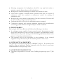
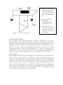
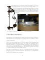
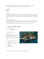
Triton Robotics has been contracted by the Project AQUA research group to design
and build a mobile robotic vessel for the purposes of tracking and position
monitoring of an underwater walking/swimming robot (AQUA). The robotic vessel
will carry a suite of sensors for the accurate positioning of the underwater robot and
the vessel itself.
The members of Triton Robotics are six senior year mechanical engineering students
at Dalhousie University in Halifax, Nova Scotia, under the direction of Dr. Marek
Kujath. This project is scheduled for completion in April of 2005.
Figure 1 AQUA Underwater Robot
1.1 PROJECT AQUA
“AQUA is a joint project between
McGill University, York University and
Dalhousie University …”. The goal of
this project is to “explore the science
technologies for the interpretation of
underwater
video
footage,
the
identification of underwater features,
the modeling of 3-D scenes using
vision and acoustics, vehicle control,
position estimation and mechanical
design.” This project is funded by the
Institute for Robotics and Intelligent
Systems (IRIS), a Canadian National
Center of Excellence. Supplementary funding is also provided by the National
Sciences and Engineering Research Council (NSERC). Refer to Figure 1 – AQUA
Underwater Robot.
The AQUA Project as a whole is broken up into three parts:
• McGill University is responsible for developing the swimming robot and using
pictures to allow the robot to determine its position, orientation and
directional velocity.
• York University has been appointed the task of developing a ‘trinocular’ stereo
camera used to take pictures used to build 3-D models of what it ‘sees’.
• A team at Dalhousie University is currently developing a vessel to be used for
tracking the position of the underwater robot using a series of sensors.
1.2 PROJECT OBJECTIVES
Triton Robotics will deliver to the client a working prototype that meets the
requirements as stated in section 2.0 Design Requirements. The final objectives of the
project are:
• Delivering a working prototype capable of remote manual remote control by
April, 2005.
• Delivering documentation that describes the design and construction of the
robotic vessel.
• Delivering procedures for the purposes of standard operation and
maintenance.
The completed robotic vessel will be delivered to the Project AQUA group. Upon
delivery, the members of Project AQUA plan to use this vessel as a prototype. They
will then perform tests to determine the effectiveness of the robotic tracking system.
The AQUA group also plans to improve upon the robotic vessel, pending the
availability of funding.
2
2.0 DESIGN REQUIREMENTS
The essential requirements for this project are outlined below:
• Dimensions of the vessel will not exceed 72” long, 48” wide, or 38” high to
enable transport of the vessel in the rear of a minivan.
• The weight of the vessel, in air, not including batteries and hydrophones, will not
exceed 200 lbs.
• The vessel will be capable of operating and maneuvering at a roll angle of 18 o
without degradation.
• At a minimum, the maneuvering system will control the vessel’s motion in two
horizontal DOF; surge and yaw. The vessel will have a zero turning radius.
• The maneuvering system will be battery powered.
• Batteries will be easily removable for replacement and/or recharging.
• The vessel will be capable of remote manual operation, adaptable for autonomous
control.
• Provisions for the mounting of the electrical payload, including the following, will
be provided:
o Inertial Navigation Sensor
o Digital Compass
o Camera with USB interface
o Laptop or PC Tower
o Two Inclinometers
o Differential GPS
o Wireless Ethernet card
o Data Acquisition Board
o Inverter
• Means will be provided for mounting four Dolphinear hydrophones.
• Budget for handover of project deliverables will not exceed $ 7,200 CDN:
o Propulsion system - $3,600 CDN
o Frame for electrical equipment - $1,000 CDN
o Waterproofing - $1,000 CDN
o Vessel Construction - $600 CDN
o Miscellaneous expenses - $1,000 CDN
• The vessel will be capable of at least two knots (~1 m/s) speed over bottom in
“Moderate Breeze” conditions (i.e. Beaufort Force 4 or 11 to 16 knots wind
speed), in a current of 2 knots.
• Operational endurance will be at least 2 hours at 75 % of maximum thrust.
• Vessel will be designed for operation in fresh or salt water and of corrosion
resistant construction.
3
• Mounting arrangement for hydrophones should be very rigid and sturdy to
maintain a precise distance between the hydrophones.
• Hydrophones should be submerged one meter below surface of water.
• Vessel will be capable of manual remote operation from shore to location of
underwater robot then switched to autonomous control for tracking of
underwater robot.
• Waterproofing of the electrical components of the raft is necessary. Provision will
also be made for cooling electrical components.
• Unobstructed field of vision for the underwater camera is required.
• Construction materials and electrical equipment magnetic field considerations
concerning possible influence on digital compass will be considered.
2.1 DELIVERABLES
Due by April, 2005 Triton Robotics will deliver the following to the client:
• A working prototype capable of remote manual control, documentation of the
design and construction of the vessel and a procedures and maintenance manual.
The contractor will provide training to Dr. Pifu Zhang and Weimen Shen for the
purposes of operation and maintenance.
• The contractor will not be responsible for the installation of any electrical
equipment except that necessary for the manual operation of the vessel.
2.2 INTELLECTUAL PROPERTY
The prototype vessel will be the property of PROJECT AQUA. The contractor has
agreed to sign an Intellectual Property Agreement with the client for any future
commercialization of the prototype vessel.
2.3 CLIENT RESPONSIBILITIES
• The client is responsible to cover the cost of building the prototype up to $ 7,200
CDN.
4
3.0 DESIGN SELECTION
The design of the vessel was approached by starting with the hull shape. The criteria
matrix below shows the initial designs considered and the criteria used to rank them.
This process resulted in the selection of four hull designs which were modeled in a
tow tank at Dalhousie University. The results of the testing will be discussed within
the sections to follow. A Work Breakdown Structure was also drafted in order to
provide a general outline of all project components that would need to be considered.
This can be seen in Appendix C – Work Breakdown Structure.
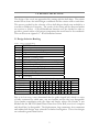
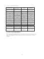
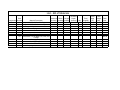
3.1 Design Selection Ranking
Table 1 - Design Selection Ranking
CRITERIA
A. Safety of operation.
B. Relative volume of hull shape.
C. Weight characteristics of hull shape.
D. Stability of hull shape.
E. Magnitude of turning radius.
F. Speed capabilities.
G. Capable of two degrees of freedom in the X-Y plane.
H. Relatively low power requirements.
I. Capable of mounting a hydrophone array to the hull.
J. Provides an unobstructed field of view for a camera.
K. Simplicity of design.
L. Placement of battery packs.
M. Sea-Keeping
All criteria were scored on a scale of 1-3 with 3 being the best.
DESIGN
A B C D E F G H I J K L
Catamaran
3 2 2 2 2 3 1 3 1 2 2 2
SWATH
3 2 2 3 2 2 1 3 3 2 2 2
Spider
2 2 1 2 3 1 3 2 1 2 1 1
Disp. Hull
3 3 3 1 1 2 2 3 1 3 3 3
Tube Hull
3 2 2 2 3 1 3 2 1 3 1 2
M
2
3
1
2
2
TOTAL
27
30
22
30
27
Due to its low score, it was determined that the spider shaped hull, which is a series
of hulls connected by radial arms, was not feasible and the idea was disregarded.
Upon further consultation with the client and faculty advisor Dr. Kujath, it was
decided that the SWATH (Small Water Plane-Area Twin Hull) was far too complex
and should also be disregarded. The displacement, large catamaran, short catamaran
and tubular hull designs were selected for further investigation. These four designs
are outlined in greater detail below.
5
TUBULAR HULL
The tubular hull (see Figure 2) design was chosen because of the
inherently low turning radius associated with a circular shape. This
design proved to be quite adept at turning but also developed poor
directional stability when placed in the tow tank. Because of the hole
through the center of the model, the two planes provided opposition to
movement through the water.
Figure 2 - Tubular Hull
SMALL CATAMARAN
This model performed better than the tubular hull but failed to fully
support the weight of the model hydrophone array. As the model
moved forward, the nose would tend to dive, eventually bringing the top
deck to the water and substantially increasing the drag. The large
catamaran (see Figure 3) proved to be better at this.
Figure 3 - Catamaran Hull
LARGE CATAMARAN
The larger version of the catamaran (see Figure 3) performed well in the trials,
supporting the hydrophone array and moved well through the water. The extra
floatation in the longer pontoons kept the nose up when moving forward. The
longer pontoons did however show a longer response time when turning due to the
greater area in contact with the water plane.
DISPLACEMENT HULL
Similar in design to a standard ship’s hull, this model (see Figure 4)
proved to move well through the water and outperformed the catamaran
designs in turning ability. This design also lends itself to the arrangement
of the electrical equipment.
Figure 4 - Displacement
Hull
PROPULSION DESIGNS
From initial research, it was determined that the selection would hinge on two types
of propulsion arrangements. These two options included a fixed arrangement, similar
to the thrusters found on ROVs, and azimuthal motors, termed “Z-Drive” motors.
Z-Drives are able to rotate 360o about their vertical shaft while
providing thrust in any direction. The use of these motors in
conjunction with one another provides a high level of
maneuverability coupled with the ability to provide significant thrust
6
Figure 5 - Z-Drive Motor
(www.ptc.com)
in one direction. This arrangement also provides an efficient use of power, limiting
the vessel’s response time when given an input by the user. Please refer to the image
of a Z-Drive motor presented in Figure 5.
The arrangement of the four fixed thrusters is non-traditional and is not commonly
used in industry. It offers a zero degree turning radius and a certain level of
simplicity. However, it does not provide an equal level of thrust in forward and
reverse and lacks maneuverability at high speeds.
The arrangement of the two transverse thrusters coupled with two fixed thrusters is a
common commercial arrangement, providing good maneuverability and a zero degree
turning radius. It does however require a more complex control system than the four
fixed arrangement and also provides unequal thrust in forward and reverse. Both
arrangements using fixed thrusters provide an inefficient response to input from the
user, increasing the amount of time required to turn the vessel.
The use of a rudder was also considered. This practice is common on commercial
vessels but does not lend itself to a tight turning radius. As a zero degree turning
radius is required for this project, the use of a rudder was disregarded.
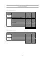
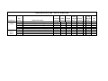
3.2 MODEL TESTING
The four main hull designs considered were constructed at a ¼ scale and tested in a
tow tank in order to gather comparative data describing drag resistance,
maneuverability and stability. A ¼ scale model of the hydrophone array was also
constructed and attached to each hull model during testing. The results of the tests
are output in the form of Effective Horse Power (EHP). This number gives the user
an indication of how much horse power will be required to propel the full scale
model. A brief overview of the test results are as follows, in Table 2:
Table 2 - Tow Tank Testing Results
Towing
Speed
Hull Shape
(m/s)
Displacement
0.51
Large Catamaran 0.51
Small Catamaran 0.51
Round
0.51
Full Scale
Speed
(knots)
1.94
1.94
1.92
N/A
Full Scale
EHP
Comments
0.21
Good stability, bow remained above surface
0.22
Good stability, bow remained above surface
0.33
Bow remained above surface, pitched forward slightly
N/A
Bow nosedived: No data
This initial tow tank testing proved to be ineffective due to the nature of the mount
used to tow the models through the tank. Located at the top and center of the
models, this method of propulsion caused the nose of the models to dive into the
water due to the heavy drag provided by the model hydrophone array. A more
practical arrangement for the propulsion involves the application of force from
7
beneath the vessel at the rear. A device was fabricated by the team to pull the models
by hand through the tank with the application of force below the water. This testing
proved to be much more successful. All of the models managed to keep their bows
above water. The results of this test showed that the long catamaran and the
displacement hull supported the hydrophone array in an effective manner and
provided the least resistance to motion through the water. Secondary tow tank
testing was performed on the models without the hydrophone array using a spring
scale and stop watch. Please refer to Appendix E – Hull and Propulsion Calculations for
more information.
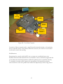
3.3 SELECTED DESIGN
Due to the complexity of the overall design it was decided that, for the initial design
selection, all components be grouped into one of the following five major areas (see
Figure 6) which will be discussed in detail below:
• Hull
• Hydrophone array
• Propulsion
• Electrical equipment
• Control System
HULL
It was determined that the conventional displacement hull design was best suited for
the particular application of this project. The wide mono-hull design will provide a
large payload capacity as well as good transverse and longitudinal stability. One of
the client requirements dictates that a camera should be installed such that it can
gather images below the surface of the water under the vessel. The flat bottom design
of the hull will allow easy installation of a clear viewing port to accommodate this
requirement. Large displacement hulls are optimally operated at low speeds, which
corresponds to the speed set in the design requirements.
This fundamental hull shape will be straightforward to construct and can be easily
designed to allow center of gravity adjustment, water contact cooling for electrical
equipment and vertical adjustment of the propulsion/hydrophone array systems. The
adjustability of the design is desirable because the client requires the vessel to be fully
operational with and without the hydrophone array attached. In comparison to the
catamaran, the displacement design will require less hull material, resulting in a lighter
vessel.
8
Figure 2 - Displacement Hull with Hydrophone
Array
•
Based on a total weight of
400lbs, the displacement
hull will be approximately
60” long, have a beam of
42”, and a total height of
24”.
•
The entire electrical
payload will be
accommodated in the
displacement hull.
•
The hydrophone array,
which will be discussed in
the next section, will be
attached to the hull using a
metal frame.
HYDROPHONE ARRAY
It was decided that the hydrophone array should be constructed of a very light
material, such as carbon fiber or aluminum. It should be constructed in such a way
that each of the four hydrophones be located 1m center to center from the others. A
rigid frame ensures the location of the hydrophones remains constant relative to one
another. In order to isolate the hydrophones from acoustic noise, the array should
extend approximately 2 meters below the surface of the water. Consisting of four
hydrophones, the array assumes a pyramid structure to maintain the required spacing
between the sensors. Refer to Figure 6 for a view of the proposed array model.
PROPULSION
It was initially determined that an arrangement of 4 z-drive motors positioned on the
corners of the vessel be used for the propulsion system. After further investigation
however, it was decided that two z-drive motors should be sufficient. Z-drives are
commonly used in dynamic positioning situations such as the one presented within
the scope of this project. The motor arrangement should provide maximum control
and a zero degree turning radius. In contrast to all other propulsion arrangements,
the 2 z-drives can be turned to thrust in any given direction. This translates into high
maneuverability, and efficient use of battery power. The only drawback to these
types of drives is the increase in system complexity.
9
ELECTRICAL EQUIPMENT
It was decided that all electrical equipment should be stored on board in waterproof
electrical enclosures. All enclosures, batteries and wiring should be mounted to a
frame that can be easily removed from the vessel. This will aid in the ease of overall
maintenance and transportation. 12 volt batteries should be used to power all
electrical systems. As the onboard computer system and hydrophone array data
acquisition board require AC power, an inverter and transformer will also be
required. The batteries will be the greatest portion of the payload weight. They will
be placed on the vessel in such a way that the load is evenly distributed and will aid in
increasing overall vessel stability. The camera used for locating the ROV when the
hydrophone array is not in use will be mounted to the bottom of the vessel on a glass
plate or window in order to provide an unobstructed underwater view. A metal
frame will be constructed to house the Crossbow Inertial Sensor at the center of
gravity (CG) of the vessel. This frame will allow the navigational system to be
calibrated so the distance from the center of the Crossbow to the focal point of the
camera is known.
Heat dissipation may be required for the compartments containing the computer
tower, inverter and transformer. This will most likely be accomplished using a fan
coil, extra fans or a cooling block directly on the sources of heat. After a
thermodynamic analysis is performed to determine the amount of condensation to be
expected, a sufficient amount of absorbent material will be installed to ensure no
water comes into contact with the electrical equipment.
CONTROL SYSTEM
The control system will consist of a remote control unit that will transmit radio
signals to six servo mechanical motors, via a receiver. This arrangement will provide a
mechanical solution to controlling and operating the vessel. The servos will be used
to independently control the speed and direction of both the bow and stern motors.
One servo will be dedicated to perform a kill switch operation. This one of the safety
features that this robotic vessel will be equipped with.
10
4.0 CONSTRUCTION DETAIL
The overall design may be broken down into five main elements (see Drawing RV000-00 General Arrangement):
• Hull
• Hydrophone array
• Propulsion
• Electrical equipment
• Control system
Although each element will ultimately be integrated into our completed design; for
the purposes of a description of construction details each will be examined separately.
4.1 HULL
Triton Robotics chose aluminum as the material for hull construction. Aluminum was
chosen for its strength, light weight, and corrosion resistance. In addition, aluminum
is a forgiving material for vessel construction, readily able to be cut and re welded to
allow for modifications or design changes.
The hull is a simple, flat bottomed, barge type design; overall length: 60”, breadth:
42”, depth: 24”. The construction of the hull consisted of aluminum sheet welded
over an arrangement of longitudinal and transverse frames. (See Figure 8)
Figure 8 – Hull Frame Arrangement
11
The outer hull plating is 5052-H32, 0.081” thick aluminum sheet. The hull is flat
bottomed over 40” of its length, as measured from the stern. The bow portion of the
hull comprises the forward 20” of the hull length. The bow shape is a simple 25”
radius rising from the flat bottom to a flat prow, which extends 6” down from the
gunnels. (See Drawing RV-100-02 Hull Frame Dimensions) The hull is flat sided with
a square stern. A flat deck covers the forward 20” and the aft 12”of the hull. For
watertight integrity, all outer hull joints were must be fully welded.
The bottom framing arrangement is of 1 ½” x 5/32” 6061-T61 aluminum channel
and 1 ½” x 1 ½” x 1/8” 6061-T61 aluminum angle. The channel was used on the
two longitudinal bottom/side seams, the transverse bottom/stern seam, and
transversely where the bow radius begins. Two longitudinal angle frames are used for
stiffening over the flat bottom section.
Stern transom framing is comprised of (in addition to the 1 ½” x 5/32” 6061-T61
aluminum channel at the stern/bottom seam) five sections of 1 ½” x 1 ½” x 1/8”
6061-T61 aluminum angle; two vertical corner pieces at the stern/side seams, a
gunnel piece, and two vertical stiffeners.
Transverse framing was incorporated where the bow radius begins its rise from the
flat bottom and 12” forward of the stern transom. This is similar to the stern transom
framing, being comprised of (in addition to the bottom channel) 1 ½” x 1 ½” x 1/8”
6061-T61 aluminum angle.
The bow framing consists of five sections of 5052-H32, 0.081” thick aluminum sheet
cut to the bow radius curvature of 25”. These pieces were bent to add structural
stability to the bow of the hull. The flat 6” deep bow section was framed with four
sections of 1 ½” x 1 ½” x 1/8” 6061-T61 aluminum angle pieces.
A watertight floor arrangement was constructed by having pieces of aluminum sheet
cut to fit on top of the floor longitudinal members. (See Drawing RV-100-05 Hull
Floor Arrangement). All welds holding the water tight floor were inspected for leaks
and repaired as needed. Inserted inside the water tight floor cavity will be
expandable, high density foam.
The cargo cover consists of a 1 ½” x 1 ½” x 1/8” 6061-T61 aluminum angle framing
arrangement that is covered by a piece of 5052-H32, 0.081 thick aluminum sheet.
(See Drawing RV-100-07 Hull Cover Arrangement).
12
After the welding of the
bottom, side, stern, and
inner floor panels to the
framing arrangement it
was necessary to cut an
opening
for
the
installation of the camera
enclosure (See Drawing
RV-301-01
Camera
Arrangement). It was a
requirement of our client
that the gyroscope be
located at the center of
gravity of the vessel and
be in close proximity to
the camera located inside Figure 9 Hole Insertion
the camera enclosure. It
was also desired that the vessel float at an even trim with the center of gravity at this
location. To do this we had to chose a gross operating weight, and at the
corresponding even keel draft locate the center of buoyancy.
A gross operating weight of 575 lbs was selected, corresponding to a draft of 7 ¾”.
Using a Maple computer program (written by Triton Robotics, see Appendix D) the
center of buoyancy was located to be 24 5/8” forward of the stern. A 10” diameter
hole was cut though the inner and outer hulls for the installation of the camera
enclosure (See Figure 9).
To properly position the two trolling
motors that are the propulsion
system used for the vessel, 12
aluminum ½” diameter bolts were
permanently welded to the hull. The
12 aluminum bolts were welded to a
sub frame assembly that is enclosed
by the bow and stern permanent
covers. (See Figure 10).
Please refer to Appendix D for
detailed Hull and Propulsion
Calculations for this vessel.
Figure 10 Motor Mounting Bolts
13
4.2 HYDROPHONE ARRAY
The array is a frame design consisting of 1” x 1” x 1/8” aluminum angle. Aluminum
was chosen because it is inexpensive relative to other rigid marine application
materials and to remain consistent with the rest of the vessels construction. Using
aluminum for the construction of the hydrophone array acts as a safeguard against
galvanic circuit formation between the hull and the array. The hydrophone array
protrudes ~1.89m below the waterline.
Four Dolphinear hydrophones will be mounted onto plates welded on a tetrahedral
truss, outlining the shape of the hydrophone array. The hydrophones have not yet
been mounted onto the hydrophone array as it is under our clients’ scope of work.
This truss will consist of six - 44” long members. This truss is then suspended from
the hull using four - 50” long pieces of angle. These pieces are clamped to the side of
the hull utilizing four quick release clamps. The array frame can be disassembled for
ease of transport. (See Drawing RV-200-01 Array – General Arrangement)
The tetrahedron shape of the hydrophone array consists of six - 44” long, 1” x 1” x
1/8” aluminum angle. The arrangement of the individual members that assemble to
create the hydrophone array can be seen in drawing RV-200-02 Array – Exploded
View. The front centre cross member of the tetrahedron is permanently mounted to
the top triangular section of the hydrophone array.
The hydrophone array mounts to four pieces of aluminum angle that are welded to
the port and starboard sides of the hull. These angles are notched for easy mounting
of the four uprights of the hydrophone array via the quick release clamps.
4.3 PROPULSION SYSTEM
Triton Robotics uses two, 50 lb thrust, 12 volt electric trolling motors, model PD 50
for propulsion of the robotic vessel. (See Figure 11)
These trolling motors come equipped with foot pedal controlled 360O electric
steering. They have variable speed control in the forward direction, and produce a
maximum thrust of 50 lb, while drawing 42 amps.
The factory supplied variable speed control and steering control systems were
modified so as to be able to be controlled via a FM remote control system. A
description of the control system may be found in Section 4.5.
14
The trolling motors are mounted on the hull centerline; one over the
stern transom and one over the bow. Two mounting brackets of ¼”
5052-H32 aluminum plate were fabricated and welded to the factory
motor brackets (See Figure 12). This enables the motors to be
mounted/dismounted from the vessel without any disassembly
of the motor assembly, as is necessary with the factory motor
brackets.
Figure 12 Motor Mounts
Figure 11 MinnKota Trolling Motor
4.3 ELECTRICAL EQUIPMENT
Triton Robotics chose aluminum as the material for all electrical frame construction.
The aluminum allows for lightweight, strong support for the containment of all the
electrical components.
There is one main electrical frame to hold the computer tower, hydrophone array
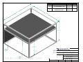
data acquisition board and power inverter. This frame (See Drawing RV-300-01
Electrical Enclosure) is of welded aluminum construction, overall dimensions 12
1/2” x 19 3/4” x 21”, made with ½” x ½” aluminum angle which was fabricated
from 0.081” thick 5052-H32 aluminum sheet. The electrical components are attached
to two flat aluminum plates located within the frame.
The frame is secured inside a 22” x 20 1/2” x 5” aluminum enclosure (See Figure 14)
designed to protect the electrical components. The enclosure is of welded 0.081”
thick 5052-H32 aluminum sheet construction.
15
Camera enclosure (See Drawing RV-301-01
Camera Arrangement) was fabricated from
0.081” thick 5052-H32 aluminum sheet. The
enclosure carries a Plexiglas viewing port to
provide an underwater view for the camera.
The enclosure is 100 % watertight to prevent
flooding of the vessel should the Plexiglas or
associated components fail.
An aluminum frame (See Figure 14) to
mount the camera and gyroscope in the
camera enclosure was constructed from 1/2”
6061-T6 aluminum square bar and 1/8” thick
5052-H32 aluminum sheet.
Figure 13 Electrical Enclosure
The four batteries will also be mounted to the vessel using small aluminum frames
made of from 0.081” thick 5052-H32 aluminum sheet.
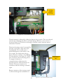
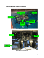
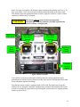
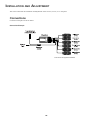
It was determined that two
separate circuits would be
incorporated into the
electrical system; one for
the motors and one for the
electrical equipment.
The motor circuit consists
of three 12V, 103 amp hr
batteries, a negative and
positive bus bar to
distribute the power, two
50lb thrust trolling motors,
a 50 amp breaker for each
motor, a main kill switch
Figure 14 Electrical Frame
operated by remote control
and a grounding line. The
grounding line is 6 gage wire and all other wiring is 8 gage. All connections are made
through spade clips. Three small frames of aluminum construction were welded to
the back wall of the hull to house the breaker system and bus bars. The breakers and
16
bus bars can however be removed from their frames by unscrewing a few small
aluminum bolts.
Figure 15 - Motor Circuit
The electrical equipment circuit
consists of one 12V 103 amp/hr
deep cycle marine battery, a
desktop computer, the Layla
hydrophone stereo equipment,
power inverter a grounding line
and a 60 amp fuse to protect the
equipment. The grounding line is
standard 6 gage wire and all other
connecting wires are standard 8
gage.
Figure 16 60 Amp Fuse for Electrical Equipment Circuit
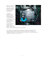
Several holes were drilled in top
of the hull and the cover of the port hole to accommodate watertight fittings for the
passage of motor, hydrophone and control leads. These permanent connections
through the hull allow components to be easily plugged in from the inside and
outside of the hull without running wires through the cover each time. This aids in
keeping the hull water tight.
17
Figure 18 - Water Tight
Connection - Hull Interior
Figure 17 - Water Tight Connection – Hull Exterior
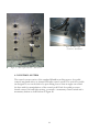
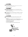
4.5 CONTROL SYSTEM
The control system consists of the standard MinnKota trolling motors foot pedal
controls integrated with a six channel FM radio control system. The stock foot pedals
are designed to rest on the deck of a sport fishing boat so that an angler can control
the boat with foot manipulations of the control pedal. Each foot pedal possesses
throttle control, left and right steering, a constant – momentary control switch and a
momentary button as shown below in Figure 20.
18
Left
Steering
Right
Steering
Throttle
Control
Momentary
Button
Constant/
Momentary
Button
Figure 20 - Foot Pedal Controller
Actuation of these controls sends a signal from the internal circuitry, to the primary
motor controller circuit. The primary functions necessary for remote vessel control
are throttle control and steering.
Modifications:
Integrating the controls with the RC servo system was considered across two
domains: electrical and mechanical. It was decided to take a mechanical approach due
to the unknown electrical parameters within the primary motor controller circuitry.
To maintain constant control opposed to momentary, the internal momentary
selector button on the foot pedals were held in the depressed position using screws.
19
RIGHT
LEFT
RIGHT
LEFT
Steering
Control
H-Bridge
Figure 21 - Foot Pedal Circuitry
Throttle intensity is adjusted by sliding the button along its track. This was achieved
remotely by connecting the slider to a simple linkage driven by a servo motor as
shown in Figure 22. This allows a full range of throttle control from the remote
transmitter controller.
Directional steering control is actuated by
pressing on the left or right side of the
steering pedal. This in turn causes a
plastic mechanism to slide either to the
left or right. The slider causes tabs to
depress 2 button switches of an H-Bridge
for each direction, (see Figure 21). Each
pair of buttons cause the steering motor
to energize clockwise or
counterclockwise which turns the
propulsion motor until the buttons are
released. The motor remains at its
orientation until the steering is actuated
again.
Throttle at
80%
Remote actuation of the steering control
is achieved through the installation of a
20
Figure 22 - Servo Actuated Throttle Control
manipulating rocker arm mounted on a shaft to simulate the rocker steering pedal as
shown in Figure 23. The rocker arm is driven through a linkage by a servo motor to
the left and right steering positions as demonstrated in Figure 23.
Steering Slider
Mechanism
Linkage
Rocker Arm
Servo Motor
Figure 23 - Servo actuated Steering Control
Figure 24 - Servo Steering Positions
Left Steer
Neutral
21
Right Steer
The servo motors are
fastened to molded
polyethylene blocks
which are attached to
the deck of each
control pedal.
In addition to
propulsion system
control, a remote
actuated kill switch
was installed. The
accompanied electrical
system contains
among other features,
two 50 amp
mechanical breaker
switches. These
breakers which allow
Figure 25 - Breaker Panel
current to flow to the
motors can be switched remotely for safety purposes.
A servo motor is mounted to the breaker panel and a plastic arm switches the
connected breaker switches Figure shows the servo arm in the off position. To
reenergize the motors, the arm rotates clockwise which pulls a cord connected to the
switches moving them to the on position.
22
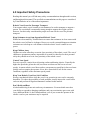
5.0 TESTING
It is important to perform testing in order to define realistic requirements and
measure actual results to see if previously defined requirements were met. The table
at the end of this section contrasts the design requirements with all final results.
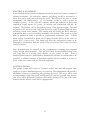
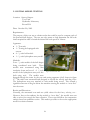
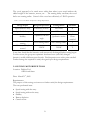
5.1 OUTBOARD TESTING
Location: Portuguese Cove Lake
Date: October 9th, 2004
Requirements:
The purpose of the test was to determine the thrust
potential and endurance of an electric motor (figure
26) and a small freshwater fishing boat. There were
no expected results for this test.
Apparatus:
• 1 – Electric trolling motor (30 lbs of thrust)
• 1 – Automotive lead acid battery
• 1 – 15 foot flat bottomed freshwater fishing
boat
• 3 – People aboard
Figure 26 Electric Motor
Method:
Three team members boarded a 15 ft long flat bottomed boat. The boat was
propelled by an outboard motor producing 30 pounds of thrust. The motor was
powered using a small fully charged automotive battery.
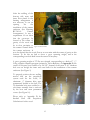
Results and Discussion:
A speed of 2.38 knots was attained at maximum battery power. It was found that the
battery (lead-acid automotive) had 45 minutes of useable power. The motor provided
sufficient thrust for three people on board. Forty five minutes of useable power
seemed be very encouraging since the battery used was small. Based on this test and
some simple calculations, it was determined that using four deep cycle marine
batteries would be sufficient.
23
5.2 INITIAL MODEL TESTING
Location: Sexton Campus
Tow Tank
Hydraulics Laboratory
Room D14
Date: October 29th, 2005
Requirements:
The purpose of this test was to obtain results that could be used to compare each of
the potential hull designs. The test was also meant to help determine the full scale
thrust required in order of reach the desired full scale speed of 4 knots.
Apparatus:
• 1 – Tow tank
• 1 – Towing sled equipped with
sensors
• 4 – ¼ scale hull models
• 1 – ¼ scale hydrophone array model
Methods:
Four - ¼ scale models of the hull shapes
being considered were built. These
models were constructed using blue
insulation foam and wood. A ¼ scale Figure 27 Tow Tank Sled
model of the hydrophone array was also
built using steel. The models were
dragged through the water by the tow tank testing apparatus (sled) shown in figure
27. The trials were automated and designed to record the velocity and drag force.
The hydrophone array was attached to each model being tested. This created a
significant amount of drag far below the waterline causing the models to “nose dive”
into the water.
Results and Discussion:
Normally, the automated tow tank test yields values for the force, velocity, etc…
However, due to the tendency for the models to “nose dive”, the models were not
able to move fast enough for data collection. These tests did allow for comparative
analysis based on qualitative results. This made it possible to choose the appropriate
model in a relative manner.
24
Figure 28a Displacement
Hull Model
Figure 28b Long
Catamaran Model
Figure 28c Short
Catamaran Model
Figure 28d Tubular Hull
Model
It was found that of the four models (Figures 28a, b, c and d); the displacement hull
(far left) was best suited to meet the design requirements.
5.3 FINAL MODEL TESTING
Location: Sexton Campus
Hydraulics Laboratory
Room D14
Date: November 10th and 11th, 2004
Requirements:
At this point in the design process, it was
necessary to know how much thrust was
required to propel the full scale vessel
maximum required speed of 4 knots.
Figure 29 Displacement Hull Model Testing
Apparatus:
• 1 – Towing stick
• 1 – Fishing line
• 1 – Spring scale (readings in pounds)
• 1 – Digital stopwatch
Methods:
This test consisted of dragging the displacement hull model with hydrophone array
(figure 29) at a lower thrust point than during the initial model testing trials. Using
the stick and fishing line, the model was dragged over a 5 meter distance. Using the
digital stopwatch and spring scale, the elapsed time and force were then measured
over this distance.
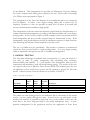
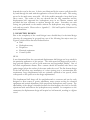
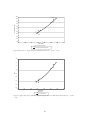
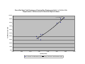
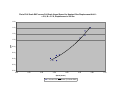
Results and Discussion:
The average velocity from these trials was ~3.25 ft/s. The measured force averaged
at ~2.4 lbs. These values were then scaled up 4 times (full scale), the results of which
are presented in figures 30 and 31.
25
100.00
y = 1.3744x2.6619
90.00
80.00
Total Resistance (lbf)
70.00
60.00
50.00
40.00
30.00
20.00
10.00
0.00
2.00
2.50
3.00
3.50
4.00
4.50
5.00
5.50
Speed (knots)
Full Scale Total Resistance (lbf)
Power (Full Scale Total Resistance (lbf))
Figure 30 Resistance vs. Speed of Full Scale Displacement Hull (L = 5 ft, B = 3.5 ft)
1.60
1.40
1.20
EHP
1.00
0.80
0.60
0.40
0.20
0.00
2.00
2.50
3.00
3.50
4.00
4.50
5.00
5.50
Speed (knots)
Full Scale EHP
Power (Full Scale EHP)
Figure 31 Effective Horsepower (EHP) vs. Effective Speed for Full Scale Model Displacement Hull (L = 5 ft, B =
3.5ft)
26
Based on figure 30 it was decided that the motors required a cumulative maximum
thrust exceeding 55 lbf.
5.4 Initial Hull Leak Test
Location: Sexton Campus
Hydraulics Laboratory
Room D14
Date: February 4th, 2005
Requirements:
The purpose of this test was to determine whether the exterior hull would leak.
Apparatus:
• The hull
• Water hose (used to fill the boat)
• Spare hose and buckets (used to empty
the boat)
• Red chalk (used to mark the seams)
Methods:
The hull was filled halfway (well above the
anticipated draft line) with water using
hose. Red chalk was then rubbed along
the seams to help detect any possible leaks
(figure 32).
Figure 32 Hull Leak Inspection
Results and Discussion:
The test was successful. There were no leaks detected. It was then determined that
the hull was ready for testing in the Dalplex pool.
5.5 FIRST TRIP TO POOL
Location: Dalplex Pool
6260 South Street
Date: FEBRUARY 9TH, 2005
Requirements:
The purpose of this test was to qualitatively determine:
27
•
•
•
•
The hull stability in the water (how does it react in water, how does it trim, etc…)
Verify the watertight integrity of the exterior hull
How stable the hull was on water
To see how the hull trimmed (fore or aft heavy) and to further verify the hull’s
resistance to leaking.
Methods:
The hull was transported to the Dalplex and placed into the pool (figures 33a and
33b). It was then rocked in a variety of manners to determine the stability. Weight
was also added in different areas to see how it would react.
Figure 33b Hull Pool Test II
Figure 33a Hull Pool Test I
Results and Discussion:
It was found that the hull exterior was waterproof. It was also very buoyant. The
hull could hold one person quite easily without increasing the draft significantly. The
trim however was unbalanced in that the bow draft was greater that that aft draft.
This would come into consideration in future efforts to balance the vessel.
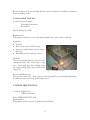
5.6 LEAK TESTING THE PIPE
Location: Sexton Campus
IC Engines Laboratory
Date: February 2005
Requirements:
Upon installation of the electrical enclosure for the stereo
camera and inertial sensor (pipe – figure 34), it was
important to determine how well it was sealed. The
28
Figure 34 Camera and
Inertial Sensor Enclosure
porthole needed to be watertight to ensure the sensitive equipment would be
safeguarded and to minimize the risk of the hull taking on water.
Apparatus:
Water
Bucket
Methods:
The enclosure was filled with water. This simulated porthole failure for the inner hull
while also testing the seal of the porthole itself. Any leakage was being monitored
around the weld seams of the pipe and outer flange as well as the gasket outer gasket
area.
Results and Discussion:
A drip leak was detected along the pipe. It was determined that this would only be an
issue if the pipe remained filled on the order of days. Therefore it is of little concern
since a detected porthole leak will not go untreated for more than on hour.
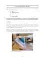
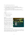
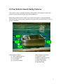
5.7 FIRST MOTORIZED TRIAL
Location: Dalplex Pool
6260 South Street
Date: March 16th, 2005
Requirements:
This test was performed to satisfy
final inspection (see figure 35).
The design aspects being tested
were:
• Speed with the hydrophone
array on
• Speed with the hydrophone
array off
• Stability
• Maneuverability
Figure 35 First Test of Full Assembly
The requirements of the design regarding these are as follows:
29
• The vessel was required to reach a speed of 2 knots in a moderate breeze (11-16
knots wind speed) in a current of 2 knots without the hydrophone array attached.
• There were no speed requirements with the hydrophone array attached.
• The vessel was required to operate at a roll angle of 18 degrees. This was not
measured during testing; however the client is satisfied with this.
• The vessel was required to be controlled in at least 2 DOF (surge and yaw) and to
also have a zero degree turning radius.
Apparatus:
• Full prototype without cover
• Tools
• ~135 lbs of concrete for ballast
• 1 – Truck (for transport)
• 1 – Dolly (for transport)
Methods:
The robotic vessel was placed in the water with the batteries, motors, circuitry,
controllers and ballast on board. The vessel was then driven remotely. The tests
performed included:
The speed testing with and without the array were the only quantitative tests
performed during this first motorized pool trial. The vessel was accelerated at full
thrust from a full stop, the elapsed time was measured from one checkpoint to
another (start to finish) using a time clock hung on the wall.
3.0
2.5
Velocity (Knots)
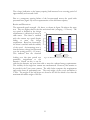
Results and Discussion:
Figure 36 presents the results from
the speed trials. The operator had
some difficulty keeping the boat on
a straight course during these trials.
This may be in part due to
inexperience controlling the vessel.
The top speed of the vessel is
expected to increase as the
operator
becomes
more
experienced.
The
speed
requirement had not been met.
2.0
1.5
1.0
0.5
0.0
1
2
Trial #
Without Array
3
With Array
Figure 36 Measured Velocities in 1st Round Testing
30
4
The vessel appeared to be much more stable than when it was tested without the
added weight of the batteries, motors, etc… The turning ability excellent; the vessel
had a zero turning radius. Control of the vessel was effectively a 3 DOF operation.
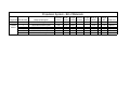
Table 3 - First Trial Results Comparison to Design Requirements
Design Aspect
Design Requirement
Testing Result
Satisfied?
Speed without Array
Effectively 4 knots
2.61 knots
N
Speed with Array
N/A
1.57 knots
Stability
Operate at 18o roll
angle
Qualitative results
N/A
No data Client
satisfied
Zero turning radius
Zero turning radius
Y
2 DOF
3 DOF
Y
Maneuverability/
turning
Maneuverability/
control
It was later found that the batteries used were mostly discharged before testing began.
For this reason, the group was optimistic that future tests (with fully charged
batteries) would yield better speed results. Final inspection was at this point satisfied.
Further testing was required to satisfy the agreed upon design requirements.
5.8 SECOND MOTORIZED TRIAL
Location: Dalplex Pool
6260 South Street
Date: March 31st, 2005
Requirements:
The purpose of this testing session was to further satisfy the design requirements.
The tests performed were:
•
•
•
•
•
Speed testing with the array
Speed testing without the array
Stability
Battery depletion
Camera vision
31
The corresponding design requirements were:
• An effective speed of 4 knots without the array attached
• No speed requirement was set for the vessel when the array is attached
• It was required that the vessel be operable, without disruption, at a roll angle of
18 degrees. This again was not measured.
• The batteries needed to provide enough power for 2 hours at 75 % thrust.
• It was required that the camera visibility be unobstructed by the hull or any part
thereof.
Apparatus:
• Full prototype without cover
• Tools
• ~120 lbs of concrete for ballast
• 1 – Truck (for transport)
• 1 – Dolly (for transport)
Methods:
The prototype was transported to the
Dalplex pool using a truck and dolly.
Once at the pool, the motors (bow
and stern) were mounted, the vessel
was placed in the water, the batteries
were placed into the vessel, the
proper electrical connections were
made and the hydrophone array was
assembled (refer to user’s manual in
the appendices). A rope was tied to
the vessel for safety purposes. Figure
37 Second Test shows the robotic
vessel in the pool with the
hydrophone array attached.
Figure 37 Second Test of Full Assembly
Speed trials were performed with and
without the array in the same manner as in the previous round of testing. The
operative roll angle again was not measured. The battery voltage was measured twice,
once before and once after testing. Finally a small single lens camera was placed
inside the electrical enclosure (pipe) to test the visibility.
32
The voltage (indicative to the battery capacity) had increased over a testing period of
approximately an hour and a half.
Due to a temporary steering failure of the bow-mounted motor, the speed trials
presented here (figure 38) are not representative of the full thrust capacity.
Velocity (Knots)
Results and Discussion:
The measured speed averaged ~2.6 knots, as shown in figure 38 without the array
was. This was higher than in the first motorized trial (averaging ~2.3 knots). The
top speed as defined in the design
3.0
requirements is effectively 4 knots in
2.5
calm water. The client is satisfied
with the current top speed despite
2.0
failing to meet this design
1.5
requirement. Based on observation,
1.0
the client is satisfied with the stability
of the vessel. An interesting note is
0.5
that the battery voltage had increased
0.0
over the testing period (~1.5 hours).
1
2
3
Trial #
This indicates that the electrical
Without Array
With Array
loading over this time period was
Figure 38 Measured Velocities in 2nd Round Testing
practically insignificant to the
batteries. Based on this, it can be
said that the batteries are more than able to meet the onboard energy requirements.
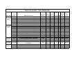
The visibility of the single lens camera was unobstructed. However, this remains to
be tested for the 3 lens stereo camera. The table below compares the requirements
and results from all performed tests. The total weight of the vessel and ballast is
575lbs. The weight of the hull alone was found to be 160 lbs which is less than the
maximum allowable weight of 200 lbs.
33
Table 4 - Design Requirements Comparison
Design Aspect
Design
Requirement
Actual
Speed without Array
Effectively 4 knots
2.61 knots
Speed with Array
N/A
1.57 knots
Stability
Operate at 18o roll
angle
Qualitative results
No data Client satisfied
Zero turning radius
Zero turning
radius
Yes
2 DOF
3 DOF
Yes
Maneuverability –
Turning
Maneuverability –
Control
Endurance
Requirement
2 hours at 75% thrust
Camera Visibility
Unobstructed by hull
Dimensional
Requirements
Hull Weight
Battery Handling
72” x 48” x 38”
LxWxH
<200 lbs
Easily removable
Adaptable for
Autonomous Control
Control System
Waterproofing
Waterproof electrical
enclosure
Satisfied?
No –
Client satisfied
N/A
Batteries more
than sufficient
Satisfied with
single lens
Pending use of 3
lens stereo camera
60” x 42” x 24”
Yes
160 lbs
Satisfied
Yes
Yes
Satisfied
Yes
Pipe electrical
enclosure is
waterproof
Partly satisfied
Partly satisfied
5.9 TESTS NOT PERFORMED
The only design requirement that was not tested for was that of measuring the roll
angle. Water tightness of the cover has not yet been tested because it is still not
complete.
34
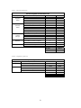
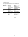
6.0 COST ANALY SIS
Table 5 - Hull Construction Cost
Hull Construction Cost
Component
Frame
Members
Material Description
6061-T6 Equal Leg Aluminum Angles
6061-T6 Channels
6061-T6 1/8" x 4" Flatbar
Amount
70.5 ft
15.7 ft
12.5 ft
Cost
$54.67
$21.97
$20.21
Hull Plating
5052-H34 Aluminum Sheet - Mill Finish
5052-H32 Aluminum Sheet - Mill Finish
97.42 ft²
16 ft²
$361.25
$183.09
1
1
1
1
4
2 gal
1 gal
$63.95
$60.00
$20.00
$15.00
$35.00
$70.00
$35.00
$75.00
Misc.
6061-T6 8" Sch. 40 Pipe
12 volt Bilge P/P and Fittings
Plexiglas
Gasket
Carrying Handle
Marine Epoxy Paint
Metal Primer Paint
Shop supplies, etc.
Sub Total:
HST
$1,015.14
$152.27
Total:
$1,167.42
Table 6 - Hydrophone Array Cost
Hydrophone Array Construction Cost
Component
Array Frame
Hydrophone
Mounting
Plate
Material Description
6061-T6 Aluminum Round Rod
Aluminum Hinge and Fasteners
Amount
42.33 ft
2
6061-T6 Aluminum Flat Bar
0.11 ft
35
2
Cost
$26.78
$10.00
$0.30
Sub Total:
HST
$37.08
$5.56
Total:
$42.64
Table 7 - Electrical System Cost
Electrical System Construction Cost
Component
Amount
Cost
Electrical
Equipment
Frame
6061-T6 Equal Leg Aluminum Angle
5052-H34 Aluminum Sheet - Mill Finish
33.8 ft
2.48 ft²
$6.51
$9.19
Box for
Electrical
Frame
6061-T6 Equal Leg Aluminum Angle
5052-H34 Aluminum Sheet - Mill Finish
Hinge for cover
Gasket
Rubber Stops
Watertight Electrical Fitting
20.7 ft
17.68 ft²
2
2
4
TBD
$16.03
$65.51
$2.00
$50.00
$10.00
TBD
Frame for
Camera
and Gyro
6061-T6 Aluminum Square Bar
5052-H34 Aluminum Sheet - Mill Finish
1.3 ft
0.28 ft²
$1.08
$1.59
4
$479.96
13.5 ft
8
$15.67
$5.00
Batteries
Battery Mounts
Material Description
10-3199-6 Motomaster Nautilus Deep
Cycle Battery 103 Amp Hr Capacity
6061-T6 Aluminum Angle
6061-T6 Aluminum Clip
Sub Total:
HST
$662.54
$99.38
Total:
$761.92
Table 8 - Propulsion System Cost
Propulsion System Construction Cost
Component
Motors
Transom Mount
Material Description
MinnKota 50 PD Trolling Motor
Amount
2
1.40 ft
5052-H2 Aluminum Plate
Miscellaneous Mounting Hardware
-
36
2
Cost
$960.00
$55.31
$10.00
Sub Total:
HST
$1,025.31
$153.80
Total:
$1,179.11
Table 9 - Control System Cost
Control System Construction Cost
Component
Material Description
Multiple Channel RC Package
Miscellaneous Integration Components
Remote
Control
Unit
Amount
1
Cost
$500.00
$100.00
Sub Total:
HST
$600.00
$90.00
Total:
$690.00
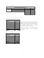
Table 10 - Total Budget Triton Robotics Anticipated
Total Budget
Component
Total Cost
Hull
$1,015.14
Hydrophone Array
$37.08
Propulsion System
$1,025.31
Electrical System
$662.54
Control System
$600.00
Sub Total:
$3,340.07
HST (15%):
$501.01
Total Cost:
$3,841.08
Please note that the initial expected budget was
$7,200.00. The expected cost we best estimated at
$3,841.08. Our Client tabulated Triton Robotics
has expensed $4,650.71 and is therefore
approximately $2,549.29 under budget.
Please refer to Appendix C – Detailed Bill of Materials
for detailed listings of all construction
components.
Table 11 - Total Expenses
Total Expenses
Component
Total Cost
Hull
$1,369.98
Hydrophone Array
N/A
Propulsion System
$1,782.50
Electrical System
$1,198.23
Control System
Sub Total:
$300.00
$3,953.11
HST (15%):
$697.60
Total Cost:
$4,650.71
37
6.0 SUMMARY AND CONCLUSIONS
Triton Robotics is confident that all of the design requirements will be met to the client’s
satisfaction on or before the handover date. The anticipated handover date with our client is
yet to be set, but it will be in late April, 2005. There are no roadblocks anticipated with
delivering the completed vessel to the client.
6.1 PATH FORWARD
Based on the completion of the tasks that are outlined in the attached Gantt Chart the
project is coming to a close. All group members will leave their contact information with the
client for future questions and consulting. A documentation package including an owner’s
manual will be supplied to the client when the handover takes place; it has been included in
this document in Appendix B, as requested.
38
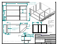
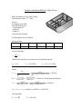
A P P E N D I X A – D R AW I N G S
ITEM
6
1
2
3
4
5
6
5
DESCRIPTION
QTY
HULL
ARRAY
VIEW PIPE
ELECTRICAL FRAME
MOTOR MOUNT
BATTERY MOUNT
1
1
1
1
1
4
4
3
2
1
Project: ROBOTIC VESSEL
Drawing: RV-000-00 GENERAL ARRANGEMENT
Unless Otherwise Noted:
Angles
Units : inches
x. xxx +/- .005 +/- 0.25 º
Aluminum
J. Slaunwhite
x. xx +/- .01
Ckd By: A. MacFarlane
x.x +/- .02
Date: JAN 13 /05 Scale: NTS
Units: Inches Sheet 1
Units : mm
x. xx +/- .15
x. x +/- .25
x +/- .50
Material:
Dwn By:
of
1
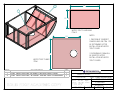
5 BOW STIFFENERS
ARE EQUAL SPACED
60
10 1/2
42
29
20 15/16
NOTES
11 1/2
A
16
20
6
DETAIL A
STIFFENER PLACED
FOR MOUNTING
OF ARRAY
24
SECTION A-A
1/4
5
A
R 25
DETAIL A
1:2
10
1. ALL CORNERS
ARE TO BE
WELDED AT 90
DEG.
CORNER PIECES
ARE TO BE CUT
AT 45 DEG
.
1/2
Dalhousie University
Project: ROBOTIC VESSEL
Drawing: RV-100-02
HULL FRAME DIMENSIONS
Unless Otherwise Noted:
Material: 6061-T6 AL
Units : mm
Angles
Units : inches
Dwn By: R. VAUGHAN
x. xx +/- .15 x. xxx +/- .005 +/- 0.25 º
x. x +/- .25 x. xx +/- .01
Ckd By: M. CARTER
x +/- .50 x.x +/- .02
Date:
Units: INCHES Sheet 2 of 7
JAN. 09/05 Scale: 1:15
41
2
1
25 1/4
39
WATER TIGHT FLOOR-BOW
ITEM 2
NOTES
1. POSITION OF VIEWPORT
CAMERA HOLE ON ITEM 1 TO
BE DETERMINED AFTER
INSTALLATION OF WATER
TIGHT FLOOR.
2. EXPANDABLE FOAM WILL
BE INSERTED AFTER
INSTALLATION OF WATER
TIGHT FLOORS
41
WATER TIGHT FLOOR
ITEM 1
ITEM
DECSRIPTION
1
0.081 THICK, 5052-H32, AL SHEET, WATER TIGHT FLOOR
2
0.081 THICK, 5052-H32, AL SHEET, WATER TIGHT FLOOR-BOW
QTY
1
1
Dalhousie University
Project: ROBOTIC VESSEL
Drawing: RV-100-05
HULL FLOOR ARRANGEMENT
Unless Otherwise Noted:
Material: 5052-H32 AL SHEET
Units : mm
Angles
Units : inches
Dwn By: R. VAUGHAN
x. xx +/- .15 x. xxx +/- .005 +/- 0.25 º
x. x +/- .25 x. xx +/- .01
Ckd By: M. CARTER
x +/- .50 x.x +/- .02
Date: JAN. 11/05
Scale: 1:15
Units: INCHES Sheet 5 of 7
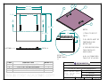
2
39 5/16
38 13/16
5 1/4
3
4
1
26 13/16
A
A
5
42 7/16
NOTES:
1 1/2
41 15/16
1. ITEM 5, TO BE CUT
TO FIT.
1/2
SECTION A - A
3. TACO WEATHER SEAL
TO BE INSTALLED
INSIDE ANGLE.
DETAIL A
DETAIL A
FRONT ANGLE
1:1
ITEM
DESCRIPTION
QUANTITY
1
2
3
4
5
0.081 THICK, 5052-H32 AL SHEET
FABRICATED HANDLES
1 1/2 x 1 1/2 x 1/8, 6061-T6 AL ANGLE
1 1/2 x 1 1/2 x 1/8, 6061-T6 AL ANGLE
1 1/2 x 1/2 x 1/8, 6061-T6 AL ANGLE, SEE DETAIL A
1
2
1
2
1
2. ALL WELDS MUST BE
CONTINUOUS AND
WATER TIGHT.
4. ALL AL FRAME ENDS
TO BE CUT AT 45 DEG.
Dalhousie University
Project: ROBOTIC VESSEL
Drawing: RV-100-07 HULL COVER ARRANGEMENT
Unless Otherwise Noted:
Material: SEE TABLE
Units : mm
Angles
Units : inches
Dwn By:
x. xx +/- .15 x. xxx +/- .005 +/- 0.25 º
R. VAUGHAN
x. x +/- .25 x. xx +/- .01
Ckd By:
x +/- .50 x.x +/- .02
M. CARTER
Date: JAN. 08/05 Scale:
1 : 15 Units: INCHES Sheet 7 of 7
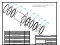
1
2
ENCLOSURE MANUFACTURED FROM 5052-H32
ALUMINIUM SCHEDULE 40 PIPE
3
4
5
6
2
7
8
7
ITEM
DESCRIPTION
QUANTITY
1
2
3
4
5
6
7
8
ENCLOSURE CAP
RUBBER GASKET
BOLTED FLANGE
10" NOMINAL PIPE
SHIP'S HULL
STUDDED FLANGE
PORTHOLE FLANGE
1/4" PLEXIGLASS
1
2
1
1
1
1
2
1
Project: ROBOTIC VESSEL
Drawing: RV-301-01 CAMERA ARRANGEMENT
ALUMINIUM
A. CALDWELL
Ckd By:
M.J. CARTER
Units: Inches Sheet 1 of 5
1:7
Unless Otherwise Noted:
Angles
Units : inches
x. xxx +/- .005 +/- 0.25 º
Units : mm
x. xx +/- .15
x. x +/- .25
x +/- .50
Date:
x. xx +/- .01
x.x +/- .02
Jan. 8, 05
Scale:
Material:
Dwn By:
Project: ROBOTIC VESSEL
Drawing: RV-200-01 ARRAY -GENERAL ARRANGEMENT
ALUMINUM
Dwn By: J. SLAUNWHITE
x. xx +/- .01
Ckd By: R. VAUGHAN
x.x +/- .02
Date:
Units: INCHES Sheet 1
JAN. 12/05 Scale: 1:20
Unless Otherwise Noted:
Angles
Units : inches
x. xxx +/- .005 +/- 0.25 º
Material:
Units : mm
x. xx +/- .15
x. x +/- .25
x +/- .50
of
16
ITEM
1
2
3
4
5
6
7
8
9
DRAWING
RV-200-14 ARRAY
RV-200-12 ARRAY
RV-200-06 ARRAY
RV-200-13 ARRAY
RV-200-05 ARRAY
RV-200-16 ARRAY
RV-200-03 ARRAY
RV-200-15 ARRAY
RV-200-04 ARRAY
QTY
- BOTTOM PLATE
- LOWER ANGLE
- UPPER CONNECTING ANGLE
- CROSSBAR ANGLE
- FRONT CORNER
- LEFT UPRIGHTANGLE
- LEFT CORNER
- RIGHT UPRIGHT ANGLE
- RIGHT CORNER
1
3
6
1
1
2
1
2
1
7
6
5
4
8
NOTE: ALL CONECTIONS BOLTED UNLESS
OTHERWISE STATED
9
3 ANGLES WELDED TO PLATE, POSITIONING TBD DURING
ASSEMBLY
3
2
1
Project: ROBOTIC VESSEL
Drawing: RV-200-02 ARRAY - EXPLODED VIEW
ALUMINUM
Dwn By: J. SLAUNWHITE
x. xx +/- .01
Ckd By: R. VAUGHAN
x.x +/- .02
Date:
Units: INCHES Sheet 2
JAN. 12/05 Scale: 1:20
Unless Otherwise Noted:
Angles
Units : inches
x. xxx +/- .005 +/- 0.25 º
Material:
Units : mm
x. xx +/- .15
x. x +/- .25
x +/- .50
of
16
21
ITEM
DESCRIPTION
1
CPU MOUNTING PLATE
2
ACOUSTIC PROCESSOR
MOUNTING PLATE
DIM.
9"X20-1/2"
X0.081"
19"X20-1/2"
X0.081"
QTY
1
1
19 1/2
12 1/2
9 17/32
1
2
Dalhousie University
Project: ROBOTIC VESSEL
Drawing: RV-300-01
ELECTRICAL ENCLOSURE
Unless Otherwise Noted:
Material: 5052-H32 AL
Units : mm
Angles
Units : inches
Dwn By: A. CALDWELL
x. xx +/- .15 x. xxx +/- .005 +/- 0.25 º
x. x +/- .25 x. xx +/- .01
Ckd By:
x +/- .50 x.x +/- .02
M.J. CARTER
Date: Jan. 8, 05 Scale: 1:4
Units: Inches Sheet 1 of 3
APPENDIX B –
OW N E R S M A N UA L
Triton Robotics
Robotic Vessel 2005
Owner’s Manual
Table of Contents
1.0 Congratulations on Your New Robotic Vessel............................................................. 4
2.0 Safety Legend ............................................................................................................... 4
3.0 Your Robotic Vessel at a Glance.................................................................................. 5
4.0 Important Safety Precautions........................................................................................ 6
5.0 Your Robotic Vessels Safety Features.......................................................................... 7
6.0 Before Operating – General Assembly Instructions ..................................................... 9
6.1 Mounting the Trolling Motors .................................................................................. 9
6.2 Launching the Boat ................................................................................................. 10
6.3 Making the Electrical Connections......................................................................... 11
7.0 Remote Control Operation.......................................................................................... 11
8.0 Disassembly ................................................................................................................ 13
9.0 Maintenance................................................................................................................ 13
10.0 Technical Information............................................................................................... 15
Appendixes
Appendix A
Appendix B
Appendix C
Minn Kota PD-50 Trolling Motor Instruction Manual
Futaba 6 Channel Radio Control System Instruction Manual
Blue Sea Systems DC Power Distribution Panel Instruction Manual
Table of Figures
Figure 1: Robotic Vessel External View ............................................................................ 5
Figure 2: Robotic Vessel Internal View.............................................................................. 5
Figure 3: Safety Features .................................................................................................... 7
Figure 4: Remote Controller ............................................................................................. 12
2
Owner Identification Information
OWNER
ADDRESS
STREET
CITY
PROVINCE
POSTAL CODE
DELIVERY DATE
OWNERS SIGNATURE
TRITON ROBOTICS SIGNATURE
3
1.0 Congratulations on Your New Robotic Vessel
Congratulations! Your selection of a Triton Robotics 2005, Robotic Vessel was a wise
investment. It will give you years of great remote boating pleasure.
One of the best ways to become familiar and enhance the enjoyment of your new robotic
vessel is to read and continually refer back to this manual. In this document you will
learn how to operate your robotic vessels driving controls and special features. After
reading this manual, be sure to keep this document with your vessel so you can refer to it
at any time.
Maintaining your vessel according to the information provided in this manual will help to
keep your remote boating trouble-free while serving to preserve your investment.
2.0 Safety Legend
Your safety and the safety of others is very important. Therefore operating this vessel
safely is an important responsibility.
To help you make informed decisions about safety, we have provided safe remote boating
operating procedures in this manual. The visual aids are to alert you to potential hazards
that could hurt yourself and others.
We recognize it is not practical or possible to warn you about all the hazards associated
with the operating or maintaining your robotic vessel. It is the responsibility of the user to
actively use their good judgment when operating or maintaining your robotic vessel.
You will find important safety information represented with these three safety symbols.
Red you will be KILLED or SERIOUSLY hurt if you
don’t follow the instructions
WARNING
Orange you can be KILLED or seriously hurt if you
don’t follow the instructions
CAUTION
Yellow you can be hurt if you don’t follow the
instructions
4
3.0 Your Robotic Vessel at a Glance
Electrical Enclosure
Bow Motor
Stern Motor
Hydrophone
Array Mount
Camera
Enclosure
Figure 1: Robotic Vessel External View
Breaker Box
Bus Bar
Battery
Figure 2: Robotic Vessel Internal View
5
4.0 Important Safety Precautions
Reading this manual you will find many safety recommendations throughout this section,
and throughout this manual. The specified recommendations on this page are considered
by Triton Robotics to be of the utmost importance.
Robotic Vessel is not for Passenger Transport
Your remote robotic vessel is under no circumstances be used to transport or support a
person. The vessels hull is structurally strong enough to support the weight a person
however, for their safety considerations people are to not use the vessel for personal
transport.
Keep Swimmers Away from Operational Robotic Vessel
Efforts have been made by Triton Robotics to ensure that swimmers in close contact with
the robotic vessel will not be in danger. However to avoid a potential dangerous situation
swimmers are to be kept at a safe distance while the robotic vessel is under its own
power.
Keep Children Away
Children are safest when they are not in close proximity of the robotic vessel. The acts of
children are spontaneous and are impossible to account for, therefore for their personal
safety they should never be in close proximity of the robotic vessel.
Control Your Speed
Excessive speed is a major factor in boating crashes and boating injuries. Generally the
higher the speeds the greater the risk, but serious accidents can also occur at lower
speeds. A remote robotic vessel does not have an extreme top speed but it does accelerate
quickly and can surprise the operator. Never drive faster than is safe for the current
conditions, regardless of the maximum speed posted.
Keep Your Robotic Vessel in a Safe Condition
Having a mechanical failure while the vessel is in operation in water can be extremely
hazardous. To reduce the possibility of such problems visually inspect the vessel before
each use and perform all regular maintenance outlined in this manual.
Don’t Drink and Boat
Alcohol and driving do not mix under any circumstances. Even one drink can reduce
your ability to respond to changing conditions, and your reaction time gets worse with
every additional drink. So don’t drink and boat, even if you are not the operator of the
robotic vessel as your assistance may be required.
6
5.0 Your Robotic Vessels Safety Features
Your robotic vessel is equipped with many features that work together to protect the
sensitive payload and any people in the surrounding area.
Some safety features do not require any action by the operator. A strong aluminum
framework forms a safety cage around the cargo payload area of the hull and serves to
protect it contents.
4
3
2
1
Figure 3: Safety Features
Safety Features Shown
(1) Water tight inside floor
(2) 24 inch deep hull
(3) Curved Bow
(4) Crash resistant hull
Safety Features Not Shown
(5) Propeller Guards
(6) Battery terminal bus bars
(7) Electronic Breaker
(8) Safety Kill Switch
(9) Buoyant Foam
7
Propeller Cages
For your own safety and the safety of all people in the near vicinity of the two rotating
propellers keep the propeller cages on at all times. It is only recommended that the
propeller cages be removed to perform maintenance operations. In these circumstances
motors must not be connected to any potential power source and extreme caution must be
used to perform the maintenance required.
WARNING
Connection of Batteries to Bus Bar Terminals
Extreme caution must be used in connecting batteries to the bus bar terminals. There is an
individual bus bar for all positive connections of each of the four batteries as well as one
for the negative connections. The person connecting the battery terminals to the bus bars
must use extreme caution not to make any direct or indirect connection between the
positive and negative terminals on the batteries as well as on the bus bars located on the
hulls interior stern wall.
CAUTION
Transporting and Placing Batteries
Be sure that when it comes time to transport or have contact with the batteries that your
hands and arms are not wet. It is a known fact that water and electricity do not mix, your
12 volt batteries are no different, therefore use caution when transporting or placing the
batteries.
8
6.0 Before Operating – General Assembly
Instructions
It is extremely important that all assembly instructions
be followed in the order they are presented here.
6.1 Mounting the Trolling Motors
The trolling motors should be mounted when the hull is on stable land.
Rear Motor:
1. Ensure motor shaft is in the locked horizontal position.
2. Place the trolling motor so that the 6 mounting bolts attached to the hull slide
into the holes drilled into the mounting plate attached to the motor.
3. Install flat and lock washers and tighten nuts to the mounting bolts using a ¾”
(19 mm) lug wrench.
4. Unlock the rear motor shaft by pulling the Grip GlideTM lever back and sliding
the shaft of the motor forward. DO NOT fully lower the shaft into the vertical
position so that the propeller is resting on the floor. This step is simply to
ensure the rear motor shaft can be moved out of the way when the front motor
is being installed.
5. Connect the positive motor lead, labeled “Lead – Pos”, to the wire connected
to the top of the hull labeled “Motor – Pos”.
6. Wrap the connection with electrical tape so that no metal is exposed.
7. Connect the negative motor lead, labeled “Lead – Neg” to the wire connected
to the top of the hull labeled “Motor – Neg”.
8. Wrap the connection with electrical tape so that no metal is exposed.
9. Plug the 7 pin male connector from the motor into the 7 pin female connector
attached to the top of the hull.
10. Connect the 9 pin female wire from the control box labeled “Rear Control F” to the 9 pin male connector mounted through the hull near the rear of the
vessel labeled “Rear Control – M”.
Front Motor:
1. Ensure motor shaft is in the locked horizontal position.
2. Place the trolling motor so that the 6 mounting bolts attached to the hull slide
into the holes drilled into the mounting plate attached to the motor.
3. Install flat and lock washers and tighten nuts to the mounting bolts using a ¾”
(19 mm) lug wrench.
4. Connect the positive motor lead, labeled “Lead – Pos”, to the wire connected
to the top of the hull labeled “Motor – Pos”.
5. Wrap the connection with electrical tape so that no metal is exposed.
9
6. Connect the negative motor lead, labeled “Lead – Neg” to the wire connected
to the top of the hull labeled “Motor – Neg”.
7. Wrap the connection with electrical tape so that no metal is exposed.
8. Plug the 7 pin male connector from the motor into the 7 pin female connector
attached to the top of the hull.
9. Connect the 9 pin female wire from the control box labeled “Front Control F” to the 9 pin male connector mounted through the hull near the front of the
vessel labeled “Front Control – M”.
10. Connect the grey wire labeled “Kill Switch” which is connected to the breaker
box at the rear of the vessel to slot #6 labeled “Kill Switch” in the Futaba
receiver pack which is located in the control box.
11. Connect the control battery pack wire into slot #1 labeled “Battery” in the
Futaba receiver pack and turn the attached switch to the ON position. The
breaker can now be switched on and off using the remote control.
12. Test the controls by hitting the kill switch on the remote control. If the breaker
position does not change, check the control connections and try again.
WARNING
If the breaker position cannot be changed using the remote
control, do not continue.
13. If the breaker position CAN be changed using the remote control, ensure that
the breaker is in the OFF position and continue on to 2.0 Launching the Boat.
6.2 Launching the Boat
With both motor shafts in the horizontal position, slowly slide the boat into the water
NOSE FIRST.
Once in the water, secure the boat to land using a tether line.
Lower the motor shafts into the vertical position by pulling back on the Grip GlideTM
lever and sliding the shafts forward while letting them rotate downwards.
WARNING
Make sure that all battery terminals are equipped with their
covers.
While using proper lifting procedures, lower all 4 batteries into their positions and secure
them using the bungee cords provided. DO NOT remove the terminal covers.
Lower the frame containing the electrical equipment into the electrical box. Ensure that
the fan side of the computer is facing the open side of the box and that all electrical cords
exit unrestricted through the back.
10
6.3 Making the Electrical Connections
Use extreme caution when working with the electrical connections. Ensure that the
breaker is in the off position before you begin.
The electrical system operates on a 12 volt system.
This does not imply the system cannot injure you.
There is the potential for high current flows in the
circuit capable of delivering large amounts of energy.
Exposure to this energy could cause severe burns.
There are two circuits within the vessel: the Motor Circuit and the Electronics Circuit.
Motor Circuit:
1. Connect the “Pos-1” wire from the positive bus bar to the positive terminal of
battery #1.
2. Connect the “Pos-2” wire from the positive bus bar to the positive terminal of
battery #2.
3. Connect the “Pos-3” wire from the positive bus bar to the positive terminal of
battery #3.
4. Connect the “Neg-1” wire from the negative bus bar to the negative terminal of
battery #1.
*The circuit is now live as indicated by the lights on the breaker box.*
5. Connect the “Neg-2” wire from the negative bus bar to the negative terminal of
battery #2.
6. Connect the “Neg-3” wire from the negative bus bar to the negative terminal of
battery #3.
Electronics Circuit:
[This circuit is not yet functioning.]
Tightly secure the top hatch to the vessel before beginning operation.
7.0 Remote Control Operation
The remote control unit for your robotic vessel is a complicated unit. The remote
controller shown in figure 4 operates both the variable control speed controllers and the
directional controllers of the robotic vessel. The robotic vessel has both a bow and stern
motor that are able to operate independently for better steering and speed control.
As shown in figure 4 below, the left controller stick operates the stern motor and the left
stick operates the bow motor. Independent thrust control is achieved by moving the stick
in the vertical direction, lowest being off and highest being maximum thrust for each
11
motor. For your convenience, the throttle control remains at the position you leave it. To
steer your robotic vessel, move the stick in the horizontal direction to the left or right.
This motion causes the appropriate motor to rotate, (right for clockwise, left for counter
clockwise), until the stick is released.
CAUTION
Kill Switch
The motors will not return to the neutral position
automatically. With the controller you must reposition the
motors to follow a straight path.
Stern Motor
Directional
Control
Bow Motor
Directional
Control
Stern
Motor
Thrust
Bow Motor
Thrust
Control
Controller
ON/OFF
Switch
Figure 4: Remote Controller
Your robotic vessel has superb maneuverability and with various propulsion motor
orientations you can move in any direction on the water surface with not much more than
its own footprint required for turning.
Note that the remote control is equipped with a kill switch. Do not hesitate to use this
switch as it was designed with safety considerations in mind. If the automatic kill switch
is used it can simply be turned back on by flicking the switch back to its original position,
when it is safe to do so.
12
It is suggested that the inexperienced driver begin at low speeds gradually increasing as
controllability becomes more comfortable. With some practice you will soon master the
control of your robotic vessel expanding the domain of aquatic exploration.
8.0 Disassembly
1.
2.
3.
4.
De-energize the motors by activating the remote kill switch.
Disconnect the “Neg-3” wire from the negative terminal of battery #3.
Disconnect the “Neg-2” wire from the negative terminal of battery #2.
Disconnect the “Neg-1” wire from the negative terminal of battery #1.
*The circuit should now be de-energized - check lights on the breakers.*
5.
6.
7.
8.
9.
Disconnect the “Pos-3” wire from the positive terminal of battery #3.
Disconnect the “Pos-2” wire from the positive terminal of battery #2.
Disconnect the “Pos-1” wire from the positive terminal of battery #1.
Remove batteries from the vessel ensuring the terminal covers are in place.
Remove vessel from the water; take care to ensure props are positioned above
the water line to avoid damage on removal.
10. Using a ¾” lug wrench, remove the nuts from the motor mounts and lift the
motors from the vessel.
11. Safely stow all equipment and ensure the top hatch is securely affixed to the
vessel.
9.0 Maintenance
Regularly maintaining your robotic vessel is the best way to protect your investment.
Proper maintenance is essential to your safety and the safety of those in the operating
vicinity of the vessel.
This section includes instructions for simple maintenance tasks, such as battery handling
and motor service. Any maintenance issues that are not detailed in this section should be
performed by a qualified technician.
Some of the most important safety precautions are outlined in this document. However,
we cannot warn you of every conceivable hazard that can arise in performing
maintenance. Only you can decide whether or not you should perform a given task.
WARNING
Failure to properly follow maintenance instructions and
precautions can cause you to be seriously hurt or killed.
Important Safety Precautions
Before you begin any maintenance make sure your robotic vessel is out of the water and
in a suitable work area.
13
Notes: To reduce the possibility of fire or explosion, be careful when working around
batteries. Always use a commercially available part cleaner to clean parts. Keep
cigarettes, sparks and flames away from the batteries.
You should wear proper eye protection and protective clothing when working
near batteries or when using compressed air.
Batteries
Check all battery terminals for corrosion (a white or yellowish powder). To remove this
powder, cover the terminals with a solution of baking soda and water. The solution will
bubble and turn brown. Wash away this new solution with clean water and wipe the
terminals clean with a dry towel.
Check battery Specific Gravity at least every 3 months with a hydrometer and recharge if
the battery SG reaches 1.240.
Store the batteries in an unheated dry area; the colder the area, the slower the rate of
discharge.
CAUTION
Battery terminals and related accessories contain lead and
lead compounds. Wash hands immediately after handling.
To connect a battery be sure to have placed it in the battery mount before attempting to
connect it. Always connect the positive terminal to the positive bus bar first. When
disconnecting batteries always disconnect the negative cable first and reconnect it last.
Clean the battery terminal with a common terminal cleaning tool or wire brush, if no
powder is present. Reconnect and tighten the cables, then coat the terminals with grease.
When it comes time to charge the batteries, remove all batteries from the robotic vessels
hull. This will prevent damage to the vessels electrical system. Again, always disconnect
the negative cable first and reconnect it last, even to the charger!
Batteries contain explosive hydrogen gas. A spark of flame can
cause the battery to explode with enough force to kill or
seriously hurt you.
Wear protective clothing and eye protection while performing battery maintenance.
WARNING
Motors
Disconnect all sources of power to trolling motors
before attempting any maintenance including
removing propeller cages.
14
Minn Kota PD-50 Trolling Motors are designed to be completely maintenance free for
users. Please consult the user manual that was supplied with the two motors if more
information is required (see Appendix A).
Motor Mounts
The motor mounting bolts should be kept lightly lubricated with an anti seize compound
or good quality grease to prevent thread galling and possible seizure of the aluminum
nuts.
Camera View port
Make sure the hull of your robotic vessel is completely out of the water before attempting
to remove the camera view port bolts. Bolts may have become seized and difficult to
remove over time. If this occurs apply a commercially available lubricant to the bolt
threads.
Use caution when removing the view port cover because there are gaskets that are
delicate and must be treated with care.
When reassembling view port bolts be sure not to over tighten bolts because bolts are
threading into aluminum threads that can be damaged.
Electrical System
Other than battery maintenance no special maintenance is required for the 12 V electrical
system.
Hull
The hull of your robotic vessel should be completely water tight and mainly maintenance
free. If any water is found to be leaking inside the hull consult a certified aluminum
welder.
10.0 Technical Information
Hull
Overall Dimensions: Length Overall:
Beam:
Moulded Depth:
60 inches
42 inches
24 inches
Total Hull Weight (Including Cover):
160 lbs
Operating Displacement:
575 lbs
15
Operating Draft at 575 lbs Displacement:
7 ¾ inches
Hull, Deck, Floor and Cover Plating:
5052-H32, 0.081 inch thick aluminum sheet
Framing Members:
1 ½ x 1 ½ x 1/8, 6061-T6 aluminum
angle and 1 ½ x ¾ x 5/32 , 6061-T6
aluminum channel
Motor Mounting Bolts:
1/2 – 13 x 2 ½, 2024-T4 aluminum bolt
Viewing Port Outer Flange Bolts:
1/2 - 20 x 1, Grade 5 SS bolt
Array
Overall Dimensions: Assembled Height:
Assembled Length:
Assembled Width:
81 inches
40 inches
45 inches
Framing Members:
1 x 1 x 1/8, 6061-T6 aluminum
angle
¼- 20 x ¾, 2024-T4 aluminum bolt
Connector Bolts:
Motors
2 x Minn Kota Model PD 50 Maximum Amp Draw:
Operating Voltage:
Variable Speed Control:
Prop:
Shaft:
Rated Thrust:
Forward Motor:
Serial #: WWAF0013578
Aft Motor:
Serial #: WWAF0013580
42
12 volts
Forward only
Weedless Wedge 2
54 inches long
50 lbs
Batteries
4 x Motomaster-Nautilus
Product #:
10-3199-6
Marine Cranking Amps:
750 A
Reserve Capacity/Amp Hour: 205 min/115 AH
Weight:
60 lbs
Serial #’s:
4851739
481752
4851741
481748
16
DC Power Distribution Panel
Blue Sea Systems
Part Number:
Amperage Rating:
Circuit Breakers:
8085
100 Amps continuous current
2 x Blue Sea, C series 50 Amp
breakers
Amperage Rating:
60 Amp fuse block
DC Power Fuse Block
Blue Sea Systems
Remote Control
Futaba Skysport 6, FM, Digital
Proportional R/C System
Transmitter:
Transmitting Frequency:
Channels:
FCC ID:
Model T6YG
79.950 MHz
6
AZPT6YG-72
Receiver:
Channels:
FCC ID:
Model FP-R127DF
7
AZP-FP-R127DF-75
17
R
R
Thank you for purchasing a Futaba 6YG. Before using your 6YG, read this manual carefully and use your R/C set
safely. After reading this manual, store it in a safe place.
See the glossary page 22 for a definition of the special terms used in this manual.
APPLICATION, EXPORT, AND RECONSTRUCTION
1. This product may be used for model airplane or surface use if on the correct frequency.
2. Exportation precautions
(a) When this product is exported from Japan, its use is to be approved by the Radio Law of the country of
destination.
(b) Use of this product with other than models may be restricted by Export and Trade Control Regulations. An
application for export approval must be submitted.
3. Modification, adjustment, and replacement of parts
Futaba is not responsible for unauthorized modification, adjustment, and replacement of parts of this product.
The Following Statement Applies to the Receiver (for U.S.A.)
This device complies with part 15 of the FCC rules. Operation is subject to the following two conditions:
(1) This device may not cause harmful interference, and
(2) This device must accept any interference received, including interference that may cause undesired operation.
•No part of this manual may be reproduced in any form without prior permission.
•The contents of this manual are subject to change without prior notice.
•This manual has been carefully written. Please write to Futaba if you feel that any corrections or clarifications should be made.
•Futaba is not responsible for the misuse of this product.
CONTENTS
-2-
SAFETY INFORMATION....................................................4
Meaning of Special Markings ....................................................4
Precautions During Flight ..........................................................4
NiCd Battery Charging Precautions ............................................6
Storage and Disposal Precautions ..............................................7
Other Precautions ........................................................................8
BEFORE USE ....................................................................9
Set Contents ................................................................................9
Name and Handling of Each Part................................................10
Transmitter Operation and Movement of Each Servo ................14
INSTALLATION AND ADJUSTMENT ................................15
Connections ................................................................................15
Adjustments ................................................................................17
USING OTHER FUNCTIONS ............................................18
Aileron/Elevator Dual Rate (D/R) Function ..............................18
Non-slip Adjustable Lever Head ................................................18
Stick Lever Spring Tension Adjustment ....................................19
Trainer Function ..........................................................................19
REFERENCE......................................................................20
Ratings ........................................................................................20
Troubleshooting ..........................................................................21
Glossary ......................................................................................22
Repair Service ............................................................................23
-3-
S
AFETY INFORMATION
To ensure safe use, observe the following precautions.
Meaning of Special Markings
Pay special attention to safety at the parts of this manual that are indicated by the following marks.
Mark
Meaning
Procedures which may lead to a dangerous condition and cause death or serious injury to
the user if not carried out properly.
Procedures which may lead to a dangerous condition or cause death or serious injury to the
user if not carried out properly, or procedures where the probability of superficial injury or
physical damage is high.
Procedures where the possibility of serious injury to the user is small, but there is a danger
of injury, or physical damage, if not carried out properly.
Symbol:
Prohibited
Mandatory
Precautions During Flight
Do not fly or turn "On" simultaneously on the same frequency.
Interference will cause a crash.
Use of the same frequency will cause interference even if the
modulation method (AM, FM, PCM) is different.
Do not fly on rainy or windy days, or at night.
Water will penetrate into the transmitter (Tx) and cause faulty
operation, or loss of control, and cause a crash.
-4-
Do not fly in the following places:
-Near other R/C flying fields (within about 2.5miles [3km]
-Near people on the ground, or objects in the air
-Near homes, schools, hospitals, or other places where there are a lot of people
-Near high tension lines, high structures, or communication facilities
Radiowave interference and obstructions may cause a crash. A crash caused by trouble in the R/C set, or the model
itself, may cause death or property damage.
Do not fly when you are tired, sick, or intoxicated.
Fatigue, illness, or intoxication will cause a loss of concentration or normal judgment and result in operation errors and a
crash.
Extend the antenna to its full length.
If the antenna is shortened, the effective range of the radio signal
will be shorter.
Always test the R/C set before use.
Any abnormality in the R/C set, or model, may cause a crash.
Before starting the engine, check that the direction of operation of
each servo matches the operation of its control stick. If a servo does
not move in the proper direction, or operation is abnormal, do not
fly the plane.
Check that the transmitter (Tx) antenna is not loose.
If the transmitter antenna comes off during use, control will be lost
and the model will crash.
When placing the transmitter (Tx) on the ground during flight preparations, be sure that the wind cannot
knock it over.
If it is knocked over, the throttle stick may be pushed to full throttle, the engine will speed up and create a very
dangerous situation.
Do not touch the engine, motor, or FET amp (speed control) during and immediately after use.
They are hot and will cause a burn.
-5-
Turning on the power switch:
Set the transmitter (Tx) throttle stick to idle.
1. Turn "On" the transmitter (Tx) power switch,
2. Then turn "On" the receiver (Rx) power switch.
Turning off the power switch:
Stop the engine,
1. Turn "Off" the receiver (Rx) power switch,
2. Then turn "Off" the transmitter (Tx) power switch.
If the Tx power switch is turned off first, the engine may go to full throttle unexpectedly and cause an injury.
Idle: The stick direction in which the engine or motor runs at the slowest speed. (usually the down position)
When adjusting the R/C set, always stop the engine.
If the engine suddenly goes to full throttle, it may cause an injury.
Nicd Battery Charging Precautions
Always charge the nicd batteries before each flight.
If the battery goes dead during flight, the plane may crash or fly away.
Charge the R/C nicd battery with the standard charger, or fast field charger. (sold separately)
Overcharging may cause burns, fire, injury, blindness, etc. due to overheating, breakage, electrolyte leakage, etc.
-6-
Do not short the nicd battery connector terminals.
Shorting the terminals will cause sparking and overheating and result in burns or fire.
Do not drop or apply strong shock to nicd battery.
The battery may short out and cause overheating or breakage
and electrolyte leakage and result in burns or damage from
chemical contents.
Storage and Disposal Precautions
Do not leave the R/C set, battery, model airplane, etc. within the reach of small children.
Touching and operating the R/C set, or licking the battery, may cause injury or damage due to chemical content.
Do not throw the nicd battery into a fire or heat the nicd battery. Also, do not disassemble or rebuild the nicd
battery.
Breakage, overheating, and electrolyte leakage may cause injury, burns, or blindness.
Nicd Battery Electrolyte
The electrolyte in a nicd battery is a strong alkali and can cause blindness if it gets in the eyes. If you get the electrolyte
in your eyes, immediately wash your eyes with water and see a doctor. If you get the electrolyte on your skin or clothes,
it may cause a burn. Immediately wash it off with water.
-7-
Do not store the R/C set in the following places:
-Where it is very hot (75°F [40C] or more) or very cold (18°F [-10C] or less).
-Where the set will be exposed to direct sunlight.
-Where the humidity is high.
-Where there is strong vibration.
-Where it is dusty.
-Where there is steam and heat.
Storing the R/C set in the places listed above may cause distortion, corrosion and product failure.
If the R/C set will not be used for a long time, remove the nicd batteries from the transmitter and the model and
store them in a dry place.
If the batteries are left in the transmitter and model, the battery electrolyte may leak out and damage the system, degrade
the performance and shorten the life of the transmitter and model.
Nicd Battery Recycling (for USA only)
Used nicd batteries are an important resource. Stick tape over the terminals and take the used batteries to a nicd battery
recycling center.
The RBRC Battery Recycling Seal on the nickel-cadmium (Ni-Cd) battery that should be used
in our product, indicates Hobbico is voluntarily participating in an industry program to collect
and recycle these batteries at the end of their useful life, when taken out of service in the United
States or Canada. The RBRC program provides a convenient alternative to placing used Ni-Cd
batteries into the trash or the municipal waste system, which is illegal in some areas. Please
call 1-800-822-8837 for information on Ni-Cd battery recycling in your area. Hobbico's
involvement in this program is part of our commitment to preserving our environment and
conserving our natural resources.
Other Precautions
Do not get fuel, oil, etc. on plastic parts.
The plastic may melt, discolor, become brittle and fail to function.
Always use Genuine Futaba transmitters, receivers, servos, ESCs, nicd batteries, and other optional parts.
Futaba is not responsible for damage, etc. caused by the use of parts
other than Genuine Futaba parts.
Use the parts described in the instruction manual and catalogs.
-8-
BEFORE USE
Set Contents
After opening the carton, first check if the following items are provided.
The set contents depend on the type of set, and these are the standard.
Transmitter
Receiver
Servo
T6YG
R147F
R127DF
S3003 (x4)
Servo horns
Receiver switch
Extension cord
Small screwdriver
and others
If the set contents are incomplete, or if you have any questions, please contact the dealer.
-9-
Name and Handling of Each Part
Transmitter T6YG (Front Panel)
Antenna /Aerial
Elevator/Aileron
Dual Rate
switch (ELV/AIL D/R)
Carrying handle
Voltage indicator
Landing gear
switch (Ch.5)
Channel 6
Elevator D/R
Aileron D/R
Trainer switch
Throttle (Mode 2)
/Rudder stick
Elevator (Mode 2)
/Aileron stick
Elevator trim lever
(Mode 2)
Throttle trim
lever (Mode 2)
Aileron trim lever
Crystal
Cover
NOTE: This graphic shows
the default assignments for
a Mode 2 aircraft system as
supplied by the factory.
Power switch
Rudder trim
lever
Neck strap
hook
Throttle ATV
adjustments
Servo reversing
switches
Power switch: Turns the transmitter "On" or "Off". In the upper position, the power is turned "On".
Voltage indicator: This is an expanded scale voltmeter. It is not calibrated in volts. When the needle deflects to the
boundary between the silver and red zones, recharge or replace the battery. Do not operate the transmitter if the needle
descends into the red area.
Antenna /Aerial: Never operate the transmitter without extending this antenna or you may create interference to other
modelers. This antenna is not intended to be removable.
Aileron, Elevator, Throttle and Rudder stick: Control each function. See page 14 for the transmitter operation
instructions.
Aileron, Elevator, Throttle and Rudder trim: Used to shift the neutral or idle position of the each servo. As the
throttle stick is moved up towards the high throttle position, the throttle trim will have less effect.
Carrying handle: Provides an easy means of transporting the transmitter.
Neck strap hook: Only clip the neck strap to this hook when neck strap use is required.
Servo reversing switches: Switches that reverse the direction of operation of the servos. The lower position is the
normal side and the upper position is the reverse side.
Channel display
1 :Aileron (CH1)
2 :Elevator (CH2)
3 :Throttle (CH3) 5 :Landing gear (CH5)
4 :Rudder (CH4) 6 :Flap (CH6)
<Operating direction display>
REV :Reverse side
NOR :Normal side
-10-
Landing gear switch: Controls the raising and lowering of retractable landing gear. Not all
models will use this function.
Flap knob: Controls the flap servo(CH6).
Dual Rate switch (AIL. D/R/ELV. D/R):
Dual Rate trimmers (AIL./ELV.):
Used to set to reduce the servo travel by flipping each Dual Rate switch. The travel
reduction for the aileron and elevator may be set by each trimmer. See page 18 for the
aileron/elevator dual rate function operation instructions.
Throttle ATV Trimer (Low/High)
Used to adjust throttle servo travel limits.
Servo travel can be adjusted independently
in each direction
Trainer switch: Controls the link between the instructor and student transmitters when using the trainer function. The
student transmitter can only be operated when this switch is being activated.
Transmitter T6YG (Rear Panel/Side Panel)
Trainer jack
Battery cover
Charging jack
Trainer jack: Connects the trainer cord when using the trainer function. The trainer cord is sold separately. See page 19 for the
trainer function operation instructions.
Battery cover: Use when replacing the battery. Slide the cover downward while pressing the area marked "PUSH".
Charging jack: Charging jack used when charging the transmitter nicd battery.
-11-
Do not charge Dry Batteries.
Charging dry batteries will cause overheating or breakage and electrolyte leakage and
result in burns or damage by the chemical content.
Charging the Nicad Battery
Never plug the special slow charger into an AC outlet other than the voltage
specified shown on the charger.
If the charger is plugged into an AC outlet other than the specified voltage, overheating,
sparking, etc, may cause burns, fire, etc.
Use the special slow charger, or R/C quick charger, sold separately, to charge the
R/C nicad batteries.
Overcharging will cause burns, fire, injury, or blindness due to overheating, breakage,
electrolyte leakage, etc.
When not using the nicad battery charger, disconnect it from the AC outlet.
The transmitter and receiver nicad batteries can be charged simultaneously or
independently.
1. Connect the charger transmitter connector to the transmitter charging jack and
the charger receiver connector to the receiver servo nicad battery.
2. Connect the charger to an AC outlet.
3. Check that the charging LED is lit.
4. At the end of charging, disconnect the charger from the AC outlet.
-12-
Receiver R127DF/R147F
"7": Not Used (CH7)
"6": Flap servo (CH6)
"5": Gear servo (CH5)
"4": Rudder servo (CH4)
"3": Throttle servo (CH3)
"2": Elevator servo (CH2)
"1": Aileron servo (CH1)
"B" Battery Connector
Antenna
Crystal
Crystal: The crystal is installed at the side of the receiver.
Servo S3003
Servo wheel
To receiver
Accessories: The following items are supplied with the set:
-Spare servo horns: Use to match the application.
-Servo mounting parts: Rubber grommets, etc.
-13-
Mounting flange
Transmitter Operation and Movement of Each Servo
Before making any adjustments, learn the operation of the transmitter and the movement of each servo. (In the following
descriptions, the transmitter is assumed to be in the operating state.)
Aileron Operation
When the aileron stick is moved to the right, the right aileron is raised and the left aileron is lowered, relative to the
direction of flight, and the plane turns to the right. When the aileron stick is moved to the left, the ailerons move in the
opposite direction. To level the plane, the aileron stick must be moved in the opposite direction. When the aileron stick is
moved and held, the plane will roll.
Right Stick
Elevator Operation
When the elevator stick is pulled back, the tail elevator is raised and the tail of the plane is forced down, the air flow
applied to the wings is changed, the lifting force is increased, and the plane climbs (UP operation). When the elevator
stick is pushed forward, the elevator is lowered, the tail of the plane is forced up, the air flow applied to the wings is
changed, the lifting force is decreased, and the plane dives (DOWN operation).
Left Stick
Right Stick
Throttle Operation
When the throttle stick is pulled back (low throttle), the engine throttle lever arm moves to the SLOW (low speed) side.
When the throttle stick is pushed forward (full throttle), the throttle lever arm moves to the HIGH (high speed) side.
Left Stick
Right Stick
Rudder Operation
When the rudder stick is moved to the right, the rudder moves to the right and the nose moves to the right, relative to the
direction of flight. When the rudder stick is moved to the left, the rudder moves to the left and the nose moves to the left.
Left Stick
-14-
INSTALLATION
AND
ADJUSTMENT
This section describes the installation and adjustment of the receiver, servos, etc. to the plane.
Connections
Connection examples are shown below.
Connection Example
•Four servos are supplied as standard.
-15-
(Connector Connection)
Insert the receiver, servo, and battery connectors fully and firmly.
If vibration, etc. causes a connector to work loose during flight, the plane may crash.
(Receiver Vibration proofing / Waterproofing)
Vibration proof the receiver and battery by wrapping them in sponge rubber or
some such material. If the receiver may get wet, waterproof them separately by
placing them in plastic bags or balloons.
If the receiver is subjected to strong vibration and shock, or gets wet, it may operate
erroneously and cause a crash.
(Receiver Antenna)
Do not cut or bundle the receiver
antenna. Also, do not bundle the antenna
together with the servo lead wires.
Cutting or bundling the receiver antenna will
lower the receiver sensitivity and shorten the
flight range and cause a crash.
Antenna installation: For aircraft, attach the
antenna to the top of the tail.
(Servo Throw)
Operate each servo over its full stroke and adjust the linkages so that the pushrod
does not bind or is not too loose.
Unreasonable force applied to the servo horn will adversely affect the servo and drain
the battery quickly.
(Servo Installation)
Install the servos to the servo mount, etc. using a rubber
grommet. Also install the servos so that the servo case does
not directly touch the servo mount or other parts of the
fuselage.
(Servo Horn Screw)
Use the horn screw supplied with the servo.
If a long screw is used, the interior of the servo may be damaged.
Power Switch Installation
When installing a receiver power switch to the fuselage, cut a rectangular hole
somewhat larger than the full stroke of the switch knob and install the switch so it moves
smoothly from ON to OFF.
Always install the switch so it will not come into direct contact with engine oil, dust, etc.
Generally, install the switch to the fuselage at the side opposite the muffler exhaust.
-16-
Adjustments
The operating direction, neutral position, and steering angle of each servo are adjustable.
The basic linkage and adjustments, control layout, and servo, Rx and Nicad
installation should conform to the fuselage design drawings and kit instruction
manual. Be sure that the center of gravity is at the prescribed position.
Adjustment Procedure
Before making any adjustments, set all the SERVO REVERSING switches on the front
of the transmitter to the lower(NOR) position and set both Dual Rate
trimmers(AIL./ELV.) to the maximum ("10") point. (Set the switches and the trimmers
with a small screwdriver, etc.)
Turn on the transmitter and receiver power switches and make the following
adjustments:
1. Check the direction of operation of each servo.
If a servo operates in the wrong direction, switch its SERVO
REVERSING switch. (The direction of operation can be changed
without changing the linkage.) Pay special attention to the direction of the aileron. (See
page 14 for a transmitter operation instruction.)
2. Check the aileron, elevator, and rudder
neutral adjustment and left-right (up-down)
throw.
Check that when the Tx trim levers are in the
center, the linkage connection point is
perpendicular to the servo. In this position the
control surfaces (aileron, elevator, rudder, etc.)
must be neutral. If the neutral position of the
control surface has changed, reset it by
adjusting the length of the rod with the clevis.
When the throw is unsuitable (different from the deflection angle specified by the kit
instruction manual), adjust it by either changing the servo horn, the position of the
linkage on the servo horn or the linkage position on the control surface horn.
3. Check the engine throttle (speed adjustment) linkage.
Change the servo horn installation position and hole position so that the throttle is
opened fully when the throttle stick is set to HIGH (forward) and is closed fully when
the throttle stick and throttle trim are set for maximum slow (backward position and
lower position, respectively).
4. After all the linkages have been connected, recheck the operating direction,
throw, etc.
Before flight, adjust the aircraft in accordance with the kit and engine instruction
manuals.
5. Fly the plane and trim each control for straight and level flight.
-17-
USING OTHER FUNCTIONS
Aileron/Elevator Dual Rate (D/R) Function
The maximum travel of the aileron and elevator servos can be altered by operating the
dual rate switch. For instance, when the switch is in the lower position, the deflection
angle is the normal deflection angle. The normal deflection angle, at the low switch
position, can be adjusted by the dual rate trimmers (AIL/ELV). The rate can be adjusted
from 50% (position 0) to 100% (position 10) of the maximum deflection angle. When
the switch is set to the upper position, spins, snap rolls, and other aerobatics that require
a maximum deflection angle can be performed.
1. Turn on the transmitter and receiver power.
2. Switch the dual rate switch (D/R) to the lower position.
3. Set the stick to the maximum travel in either direction.
4. Using the trimmer, adjust the servo horn to the desired angle.
Adjust each channel (AIL/ELV) by repeating steps 1 through 4.
*When not using the dual rate function, set the AIL and ELV trimmers to 100%
(fully clockwise).
Non-slip Adjustable Lever Head
The length of the stick head can be adjusted.
1. Unlock two heads A and B by turning them in the
arrow directions.
2. Adjust the stick to the most comfortable length and
lock the heads by turning them in the opposite direction
of the arrows.
-18-
Stick Lever Spring Tension Adjustment
The operating feel of the aileron, elevator, and rudder sticks can be individually adjusted
by adjusting the stick spring tension.
1. Remove the four transmitter rear case screws
and carefully remove the rear case.
2. Adjust the spring tension by turning the screw
of the channel you want to adjust (clockwise to
stiffen counter-clockwise to soften).
3. Close the rear case and tighten the four
screws.
Trainer Function
The trainer function is a very effective way for training students. To use it, the special
trainer cord TC-FM (FUTM4410 USA only - sold separately) is necessary.
The special trainer cord can be connected to SKYSPORT4, SKYSPORT6, 7U series, 8U
series, and PCM1024Z series transmitters.
Never turn on the student transmitter power switch.
Turning on the power switch will cause interference and a crash.
Set the student and instructor transmitter functions and trims to the same settings.
For example, if the direction of operation is reversed, control will be lost and the plane
will crash.
Both transmitters must have the modulation type that is FM type.
If the modulation type is different, control is impossible.
Connection
Connect the student and instructor
transmitters with the trainer cord.
Operating Instructions
Instructor side: Turn "on" the power switch and extend the antenna to its full length.
When the trainer switch is not activated, the instructor has control. When the trainer
switch is activated, control is transferred to the student. Release the switch to retain
control.
Student side: Never turn on the power switch.
-19-
REFERENCE
Ratings
Transmitter T6YG
(2 sticks, 6 channels, FM transmitter)
Receiver R127DF
(7 channels, FM receiver)
Transmitting frequency: 29, 35, 36, 40, 41, 50,
60, 72, or 75 MHz
Modulation method: FM(Frequency Modulation)
Power requirement: 12V (penlight battery x8) or
9.6V nicad battery
Current drain: 180mA
Receiving frequency: 50, 72, or 75 MHz
Intermediate frequency: 1st IF 10.7MHz
2nd IF 455kHz
Power requirement: 6V (penlight battery x4), 4.8V or 6v NiCd
battery (common with servo)
Current drain: 10mA
Size: 64.3 x 35.8 x 21mm
Weight: 40.5g
Servo S3003
(Standard servo)
Power requirement: 4.8V or 6V (common with
receiver)
Current drain: 8mA (idle)
Output torque: 3.2kg-cm at 4.8V
Operating speed: 0.23sec/60 degrees at 4.8V
Size: 40.4x19.8x36mm
Weight: 37.2g
Receiver R147F
(7 channels, FM receiver)
Receiving frequency: 29, 35, 36, 40, 41, 72 MHz
Intermediate frequency: 455kHz
Power requirement: 6V (penlight battery x4), 4.8V or 6v NiCd
battery (common with servo)
Current drain: 14mA
Size: 24.2 x 64 x 17.6mm
Weight: 26g
Note: Specifications and ratings are subject to change without prior
notice and may differ from country to country.
-20-
Troubleshooting
If your R/C set does not operate, its range is short, it intermittently stops operating, or it
operates erroneously, take the action shown in the table below. If this does not correct
the trouble, please contact a Futaba dealer.
Check point
Check item
Action
Transmitter/receiver battery
Dead battery.
Dirty contacts.
Replace the battery. Charge the
NiCd battery.
Reload the batteries in the
correct polarity.
If the contact spring is deformed,
correct it.
Wipe with a dry cloth.
Transmitter antenna
Loose.
Not extended to full length.
Screw in.
Extend fully.
Crystal
Disconnected.
Wrong band.
Different from specification.
Push in.
Match transmitter/receiver band.
Replace with specified crystal.
Connector connection
Incorrect wiring.
Disconnection.
Reinsert.
Push in.
Receiver antenna
Close to other wiring.
Cut?
Bundled?
Separate from other wiring.
Request repair.
Install in accordance with
instruction manual.
Servo linkage
Binding or looseness
Adjust at the fuselage.
Motor (electric motor plane)
Noise countermeasures.
Install a noise absorbing
capacitor.
Incorrect loading.
Faulty contact connection.
-21-
REFERENCE
Glossary
The following defines the symbols and terms used in this instruction manual.
Aileron (AIL)
Control surface on the left and right sides of the
main wing of an aircraft. It usually controls
banking of the aircraft.
Channel
Represents the number of control functions. It
can also represent the number of servos that
are operated.
Down
Means "down" elevator. It is the direction in
which the trailing edge of the elevator moves.
Servo horn
A part that is installed to the shaft of a servo
which changes the rotating motion of the servo
to linear motion and transmits the linear motion
to a rod. Servo horns come in various shapes.
Servo mount
Base for installing a servo in the aircraft.
Stick
Control for operating the transmitter.
Throttle (TH)
Dual Rate (D/R)
Reduces the servo travel by flipping a switch.
Elevator (ELV)
Control surface that moves up and down on the
horizontal stabilizer of an aircraft. It usually
controls up and down. (Altitude)
Part that controls the air mixture at the engine
intake. When opened (throttle high position), a
large air mixture is sucked in and the engine
speed increases. When closed (throttle low
position), the engine speed decreases.
Trim
Mechanism that connects the servos and the
fuselage or wing control surfaces.
A device that fine adjusts the neutral point of
each servo for safe flying. It is a mechanism
that corrects unbalanced tendencies of the
aircraft.
Modulation Method
Up
Linkage
Two modulation methods are used with radio
control: AM (Amplitude Modulation) and FM
(Frequency Modulation). Radio sets for aircraft
mainly use FM. Another method that encodes
and transmits the modulated signals is called
"PCM".
Neutral
Means the neutral position. It is the state in
which a transmitter stick returns to the center
when not operated.
Normal (NOR)
For the servo reversing function, it is the normal
side. The opposite side is the reverse side.
Rudder (RUD)
Tail control surface that controls the direction of
the aircraft.
Reverse (REV)
With the servo reversing function, this refers to
the reverse side. The opposite side of reverse is
the normal side.
Rod
A wire that connects the servos and the control
surfaces.
-22-
Means "up" elevator. It is the direction in which
the trailing edge of the elevator moves.
Repair Service
(for USA)
Before requesting repair, read this instruction manual again and recheck your system.
Should the problem continue, request repair service as follows:
Describe the problem in as much detail as possible and send it with a detailed packing
list together with the parts that require service.
•
•
•
•
•
Symptom (Including when the problem occurred)
System(Transmitter, Receiver, Servos and model numbers)
Model (Model name)
Model Numbers and Quantity
Your Name, Address, and Telephone Number.
R
1610 Interstate Dr.
Champaign, IL 61822
(217) 398-0007
FUTABA CORPORATION
Makuhari Techno Garden Bldg., B6F 1-3 Nakase, Mihama-ku, Chiba 261-8555, Japan
Phone: (043) 296-5118
Facsimile: (043) 296-5124
-23-
WARNING
Marine Electrical Products
DC Power Distribution Panel
@
PN 8023 / PN 3023 / PN 8025 / PN 3025 / PN 8264 / PN 3264
PN 8375 / PN 3375 / PN 8376 / PN 3376 / PN 8377 / PN 3377
Panel Specifications
Material:
Primary Finish:
Final Panel Finish:
Circuit Breakers:
Amperage Rating:
Voltage Rating:
0.125” 5052-H32 Aluminum Alloy
Chemical Treatment per Mil Spec C-5541C
Graphite color 2 part textured Polyurethane
15 amp AC/DC Magnetic 65V DC/277V AC Maximum
All components are sized for 100 Amps of
continuous current
Panels are rated for 12 or 24 volt DC distribution.
Configure your panel with the supplied voltage
identification labels.
PN
Overall Dimensions: 8023/3023
8025/3025
8264/3264
8375/3375
8376/3376
8377/3377
Mounting Centers: 8023/3023
8025/3025
8264/3264
8375/3375
8376/3376
8377/3377
Inches
Millimeters
5-1/4 x 7-1/2
5-1/4 x 3-3/4
14-3/4 x 7-1/2
14-3/4 x 4-1/2
5-1/4 x 11-1/4
10-1/2 x 7-1/2
4-7/16 x 6-11/16
4-7/16 x 2-15/16
13-29/32 x 6-11/16
13-29/32 x 3-11/16
4-7/16 x 10-7/16
9-11/16 x 6-11/16
133.4 x 190.5
133.4 x 95.3
374.7 x 190.5
374.7 x 114.3
133.4 x 285.8
266.7 x 190.5
112.7 x 169.9
112.7 x 74.6
353.2 x 169.9
353.2 x 93.7
112.7 x 256.1
246.1 x 169.9
It is not possible within the scope of these instructions to fully acquaint
the installer with all the knowledge of electrical systems that may be
necessary to correctly install this product. If the installer is not
knowledgeable in electrical systems we recommend that an electrical
professional be retained to make the installation.
If either the panel front or back is to be exposed to water it must be
protected with a waterproof shield.
The panels must not be installed in explosive environments such as
gas engine rooms or battery compartments as the circuit breakers are
not ignition proof.
The main positive connection must be disconnected at the battery post
to avoid the possibility of a short circuit during the installation of this
distribution panel.
@
@
@
Guarantee
Any Blue Sea Systems product with which a customer is not satisfied
may be returned for a refund or replacement at any time.
Useful Reference Books
Calder, Nigel, 1996: Boatowner’s Mechanical and Electrical Manual,
2nd edition, Blue Ridge Summit, PA: TAB Books, Inc.
Wing, Charlie, 1993: Boatowner’s Illustrated Handbook of Wiring,
Blue Ridge Summit, PA: TAB Books, Inc.
Applicable Standards
• American Boat and Yacht Council (ABYC) Standards and Recommended
Practices for Small Craft sections: E-1, E-3, E-9.
• United States Coast Guard 33 CFR Sub Part 1, Electrical Systems.
Blue Sea Systems Inc.
425 Sequoia Drive
Bellingham, WA 98226 USA
Document 9467 Rev.I
Phone (360) 738-8230
Fax (360) 734-4195
E-mail [email protected]
www.bluesea.com
Installation
1.
Disconnect all AC and DC power
Chart for other situations. Remember that the length of the circuit is the
total of the positive wire from the power source and the negative wire
back to the DC Negative Bus. Be certain that there is a fuse or circuit
breaker of the correct size protecting the positive feed wire. In the
case of the 24 position panel, jumpers from positive bus to positive bus
and from negative bus to negative bus should be the same size as the
positve feed and the negative return wires.
Before starting, disconnect the main positive cable from all batteries to
eliminate the possibility of a short circuit while installing the distribution
panel. Also disconnect the AC shore power cord from the boat to
eliminate the possibility of electrocution from AC wiring in the proximity
of the DC distribution panel.
2.
Apply Voltage Label
All panel components are sized for 12 or 24 Volt systems. Use the
labels provided to permanently identify the system voltage and its type
(DC) as required by ABYC. Apply the appropriate voltage label to
the recessed area on the front of the panel.
3.
5.
Select mounting location and cut opening
Connect the positive (red) branch circuit wires to the load terminals of
each circuit breaker.
Select a mounting location which is protected from water on the panel
front and back and is not in an area where flammable vapors from
propane, gasoline or lead acid batteries accumulate. The circuit
breakers used in marine electrical panels are not ignition protected and
may ignite such vapors.
Using the panel template provided, make a cut out in the mounting
surface where the distribution panel is to be mounted. Do not yet
fasten the panel to the mounting surface.
4.
Connect each negative (black or yellow) branch circuit wire to the DC
Negative Bus. DO NOT CONFUSE THE DC NEGATIVE BUS WITH
THE DC GROUNDING BUS.
6.
Installation of Backlight System
Connect the yellow negative wire to the panel negative bus.
Install positive feed wire and negative return
Determine the positive feed (red) and negative return (black or yellow)
wire size by calculating the total amperage of the circuits that will be
routed through the panel. Blue Sea Systems’ electrical panels are
rated at 100 amp total capacity. The positive feed wire must be sized
for 3% voltage drop at the 100 amp panel rating or the maximum
amperage that will be routed through the panel in any particular
installation, whichever is less. It is recommended that the positive feed
wire be sized for the full panel capacity, which, in most cases, will
require at least 2 AWG wire, assuming a 10 foot wire run between the
panel and the batteries in 12 volt systems. Refer to the Wire Sizing
Install branch circuit wires
Determine the proper wire size for each branch circuit using the
guidelines in step 4. Verify that the standard 15 amp circuit breakers
installed in the panel are large enough for each branch circuit. Remove
and replace with a higher amperage any that are undersized.
To activate the label lights by the boat’s battery switch, connect the red
positive wire to the DC panel positive bus.
To activate the label lights by an independent switch or breaker,
connect the red positive wire to the load side of the switch or breaker.
7.
Optional - install grounding system wire
The grounding wire (bare, green or green with yellow stripe and
normally non-current carrying) should not be confused with the
negative ground wire (black or yellow and normally current carrying).
Installation (continued)
In Boatowner’s Illustrated Handbook of Wiring, Charlie Wing identifies
three purposes of DC Grounding:
1. Holding conductive housings of low voltage (under 50 volts) DC
devices at ground potential by providing a low resistance return
path for currents accidentally coming into contact with the device
cases.
2. Providing a low resistance return path for electrical current,
preventing stray currents that may cause corrosion.
3. Grounding metal electrical cases to prevent emission from inside
or absorption from outside of radio frequency noise (RFI).
Optional Branch LED’s
This Panel is supplied with LED’s pre-installed in all optional branch
positions. For future expansion of the panels remove the positive leg of
the LED from the negative busbar and connect it to the load side of the
corresponding branch circuit breaker.
Note
This Blue Sea Systems electrical distribution panel is furnished with
15 amp AC/DC circuit breakers. This rating was selected to minimize
the need for removing the panel’s circuit breakers and reinstalling
different size circuit breakers. As shown in the Wire Sizing Chart
included with these instructions, even 16 AWG wire, which is the
minimum wire size recommended by ABYC, has an allowable
amperage greater then 20 amps. Additionally, it would be rare to have
more than 15 amps of current flowing in any one circuit. Therefore,
15 amp circuit breakers will satisfy the vast majority of marine circuit
protection situations.
ABYC requires that grounding wires be sized no smaller than one wire
size under that required for current carrying conductors supplying the
device to which the grounding wire is connected.
A full treatment of this subject is not possible within the scope of these
instructions and there is controversy surrounding the general subject of
DC bonding, of which DC grounding is a component. It is suggested
that installers not familiar with this subject consult one of the reference
books listed elsewhere in these instructions.
8.
The Purpose of a Panel
There are five purposes of a marine electrical panel:
• Power distribution
• Circuit (wire) protection
• Circuit ON/OFF switching
• Metering of voltage and amperage (In panels with meters)
• Condition Indication (circuit energized)
Apply branch circuit labels and mount panel
Apply a label for each of the branch circuits from the 30 basic labels
provided. If the appropriate label is not included, the Extended Label
Set of 120 labels may be ordered from your marine supplier (PN 8039).
Individual labels are also available from Blue Sea Systems for specific
applications. Refer to the label order form for a complete listing of
individual labels.
Related Products from Blue Sea Systems
PanelBack Insulating Covers
High Amperage Fuses and Circuit Breakers for positive feed wires
High Amperage Battery Switches
Terminal Blocks and Common Bus Connectors
Fasten the panel to the mounting surface using the panel mounting
screws supplied with the panel.
9.
Testing
Reconnect the main positive cable to the battery terminals and turn the
main switch on to supply power to the panel. Turn on all branch circuits
and test the voltage at the panel. Compare this voltage to the battery
terminal voltage to determine that the voltage drop is within 3%. With
all branch circuits still on, test the voltage at one device on each circuit
to determine that there is a 3% or 10% drop as is appropriate.
Wire Sizing Chart
1.
2.
3.
4.
5.
DC BACKLIGHT
BOARD
Calculate the maximum sustained amperage of the circuit. Measure
the length of the circuit from the power source to the load and back.
Does the circuit run in an engine space or non engine space.
Calculate Famps (Feet x amps). Multiply circuit length by max. current.
Base the wire on either the 3% or 10% voltage drop. In general, items
which affect the safe operation of the boat and its passengers (running
lights, bilge blowers, electronics) use 3%; all other loads use 10%.
Starting in the column which has the right voltage and voltage drop,
run down the list until arriving at a value which is greater than the
calculated Famps. Move left to the Ampacity column to verify that the
total amperage of the circuit does not exceed the maximum allowable
amperage of the wire size for that row. If it does, move down until the
wire ampacity exceeds the circuit amperage. Finally, move left to the
wire size column to select the wire size.
Example
a. A 12 volt system at 10% drop with a 40’ circuit x 45 amps = 1800
Famps. A wire size of 8 is required.
FUSE
1.0 TO 2.0A
FROM DC
POSITIVE
TO DC
NEGATIVE
Wiring Diagram
DC Power Distribution Panel
(PN 8023 /PN 3023 shown for reference)
APPENDIX C – DETAILED BILL
OF MATERIALS
Hull - Bill of Materials
Part
Component Number
Frame
1
Members
2
3
4
5
6
7
8
9
10
11
12
13
14
Hull Plating
15
16
17
18
19
20
21
Material Description
6061-T6 Equal Leg Aluminum Angle
6061-T6 Equal Leg Aluminum Angle
6061-T6 Equal Leg Aluminum Angle
6061-T6 Equal Leg Aluminum Angle
6061-T6 Equal Leg Aluminum Angle
6061-T6 Equal Leg Aluminum Angle
6061-T6 Equal Leg Aluminum Angle
6061-T6 Equal Leg Aluminum Angle
6061-T6 Equal Leg Aluminum Angle
6061-T6 Equal Leg Aluminum Angle
6061-T6 Channels
6061-T6 Channels
5052-H32 Aluminum Plate
5052-H32 Aluminum Sheet - Mill Finish
5052-H32 Aluminum Sheet - Mill Finish
5052-H32 Aluminum Sheet - Mill Finish
5052-H32 Aluminum Sheet - Mill Finish
5052-H32 Aluminum Sheet - Mill Finish
5052-H32 Aluminum Sheet - Mill Finish
5052-H32 Aluminum Sheet - Mill Finish
5052-H32 Aluminum Sheet - Mill Finish
Thickness Width Length
(inches) (inches) (inches)
0.125
1.5
4.5
0.125
1.5
21
0.125
1.5
22.375
0.125
1.5
26.5
0.125
1.5
38.6875
0.125
1.5
39
0.125
1.5
42
0.125
1.5
60
0.125
1.5
39.3125
0.125
1.5
42.4375
0.15625
0.75
40
0.15625
0.75
42
0.250
0.5
39
0.081
5
26
0.081
41
39
0.081
41
25.25
0.081
41.938 38.8125
0.081
41.5
20.25
0.081
42
24
0.081
24
60
0.081
42
84
Channel
Depth
(inches)
1.5
1.5
-
Qty
2
2
7
2
2
1
3
2
2
2
2
2
1
5
1
1
1
1
1
2
1
Total
Length(ft)
0.75
3.50
13.05
4.42
6.45
3.25
10.50
10.00
6.55
7.07
6.67
7.00
3.25
10.83
3.25
2.10
3.23
1.69
2.00
10.00
7.00
Total
Area
(ft2)
0.14
4.51
11.10
7.19
11.30
5.84
7.00
20.00
24.50
Total
Weight
(lbs)
0.32
1.48
5.51
1.86
2.72
1.37
4.43
4.22
2.76
2.98
3.40
3.57
0.4768
5.1503
12.67
8.20
12.90
6.66
7.99
22.82
27.95
Total
Cost
$0.90
$4.20
$15.66
$5.30
$7.74
$3.90
$12.60
$12.00
$7.86
$8.49
$20.53
$21.56
$1.48
$12.00
$29.52
$19.11
$30.05
$15.52
$18.61
$53.17
$65.13
Hull - Bill of Materials
Part
Number
Component
Misc.
22
23
24
25
26
27
28
29
30
31
32
33
Material Description
6061-T6 10" Sch. 40 Pipe
Cover: 5052-H32 Aluminum Plate
Flange: 5052-H32 Aluminum Plate
Plexiglass
Gasket
Latch
Taco Weather Seal
Sea Sense: 12 volt Bilge P/P, Float, and
Fittings
Carrying Handle
Marine Epoxy Paint
Metal Primer Paint
Shop supplies, fasteners, etc.
Thickness Width Length
(inches) (inches) (inches)
12
0.250
13
13
0.250
13
13
Channel
Depth
(inches)
Qty
1
1
4
1
1
8
1
Total
Length(ft)
1.00
1.08
4.33
Total
Area
(ft2)
1.17
4.69
Total
Weight
(lbs)
14.00
4.13
16.53
Total
Cost
$50.00
$12.81
$51.24
$20.00
$15.00
$80.00
$25.00
1
$60.00
4
2 gal
1 gal
$10.00
$70.00
$35.00
$75.00
Hydrophone Array - Bill of Materials
Component
Array
Frame
Part
Number
1
2
3
4
5
6
Material Description
6061-T6 Aluminum Angle
6061-T6 Aluminum Angle
6061-T6 Aluminum Angle
6061-T6 Aluminum Angle
1/4" x 3/4" Stainless Steel Nuts and Bolts
5052-H32 Aluminum Sheet - Mill Finish
Hydrophone
Bottom
Plate*
*Cost included in Bill of Materials for the hull
Density
Total
(lbs/ft)or
Diameter
Thickness Width Length
Weight
Total
(inches) (inches) (inches) (lbs/ft2) (inches) Qty (lbs)
Cost
0.125
1
50
0.282
4
4.70
$12.93
0.125
1
44
0.282
1
1.03
$2.84
0.125
1
32
0.282
6
4.51
$12.41
0.125
1
8
0.282
12
2.26
$6.20
40
$20.00
0.081
1.141
8
1
0.398
Propulsion System - Bill of Materials
Component Part Number
1
Motor
2
Transom
3
Mount
4
5
6
Material Description
50 PD Trolling Motor
5052-H32 Aluminum Plate
5052-H32 Aluminum Plate
5052-H32 Aluminum Plate
5052-H32 Aluminum Plate
Miscallaneous Mounting Hardware
Shaft
Density
Total
Thickness Width Length Diameter Length (lbs/ft) or
Weight
(inches) (inches) (inches) (inches) (inches) (lbs/ft²) Qty (lbs)
54
2
0.25
0.25
0.25
0.25
-
3.00
3.00
3.00
6.00
-
26.00
14.00
3.00
12.00
-
-
-
3.521
3.521
3.521
3.521
-
4
4
8
2
-
7.63
4.11
1.76
3.52
-
Total Cost
$1,550.00
$23.65
$12.73
$5.46
$10.92
$10.00
Electrical System - Bill of Materials
Density
(lbs/ft)
Total
Thickness Width Length
or
Weight
(inches) (inches) (inches) (lbs/ft²) Qty (lbs)
0.081
1
12.5
1.141
4 0.3962
0.081
1
19.5
1.141
6 0.9271
0.081
1
21
1.141
6 0.9984
0.081
9.5
21
1.141
1 1.5808
0.081
19.5
21
1.141
1 3.2447
Part
Number
1
2
3
4
5
Material Description
5052-H32 Aluminum Sheet - Mill Finish
5052-H32 Aluminum Sheet - Mill Finish
5052-H32 Aluminum Sheet - Mill Finish
5052-H32 Aluminum Sheet - Mill Finish
5052-H32 Aluminum Sheet - Mill Finish
Box for
Electrical
Frame
5
6
7
8
9
10
11
12
13
5052-H32 Aluminum Sheet - Mill Finish
5052-H32 Aluminum Sheet - Mill Finish
5052-H32 Aluminum Sheet - Mill Finish
5052-H32 Aluminum Sheet - Mill Finish
5052-H32 Aluminum Sheet - Mill Finish
5052-H32 Aluminum Sheet - Mill Finish
Hinge for cover
Gasket
Rubber Stops
0.081
0.081
0.081
0.081
0.081
0.081
1
1
1
20.5
14
14
14
20.5
22.5
22.5
20.5
22.5
1.141
1.141
1.141
1.141
1.141
1.141
4
4
4
2
2
2
0.4437
0.6497
0.7131
7.3095
4.5482
4.9919
$1.44
$2.11
$2.32
$23.76
$14.78
$16.22
Frame for
Camera
and Gyro
14
15
5052-H32 Aluminum Sheet - Mill Finish
6061-T6 Aluminum Square Bar
0.125
-
4
0.5
5
4
1.762
0.294
2
4
0.4894
0.392
$1.59
$1.08
Batteries
10-3199-6
4
200
$479.96
Battery
Mounts
16
17
18
8
8
8
0.8462
0.4374
$2.75
$1.42
$1.00
Component
Electrical
Equipment
Frame
Motomaster Nautilus Deep Cycle Battery 103 Amp
Hr Capacity
5052-H32 Aluminum Sheet - Mill Finish
5052-H32 Aluminum Sheet - Mill Finish
6061-T6 Aluminum Clip
6.9
0.081
0.081
8.9
(height)
1
1
13.1
13.35
6.9
1.141
1.141
Total
Cost
$1.29
$3.01
$3.24
$5.14
$10.55
Control System - Bill of Materials
Part
Component Number
1
Remote
2
Control
Unit
Material Description
Futaba 8 Channel RC Package
Miscellaneous Integration Components
Density
(lbs/ft)
Total
Thickness Width Length Diameter
or
Weight
Total
(inches) (inches) (inches) (inches) (lbs/ft²) Qty (lbs)
Cost
1
$500.00
$100.00
APPENDIX D – HULL AND
PROPULSION CALCULAT IONS
Sample Calculation Draft
Monotype Displacement Hull
Hull Parameters based on ¼ model
Longitudinal 72” ~ model 18”
Beam 42” ~ model 10 ½”
Vertical Depth ~ model 6”
Bow Radius 25” ~ model 6 ¼”
Assumptions
Estimated 700lbs Payload
Usage for Fresh Water
Calculations Treat Hull as a Solid Block
Archimedes Principle
∆ = γ *∇
700lbs *
∇=
∆
γ
=
γ =
1
36 ft / tonn
3
1 tonn
= 0.35tonnes
2000 lbs
0.35 tonnes
= 12.6ft 3
1
36 ft 3 / tonn
∇ = Volume to be displaced by hull
∆ = 700 lbs at Full Ship Scale ~ 10.9 lbs at Model Scale
Estimated Draft T is :
12.6 ft3 = 6 ft x 3.5 ft x T
T = 0.6 ft or 7.2 inches
Sample Calculation Effective Horse Power
EHP Calculation for Tow Tank Testing
Performed November 17th, 2004
Trial # 1
For Displacement Hull
Full Ship Dimensions
- Longitudinal 60”
- Beam 42”
- Depth 16”
Correction Factor 0.004
No Hydrophone Array Attached
Measured Data:
Trial #
Distance
(ft)
1
16.416
Time (s)
5.44
Velocity
(ft/s)
3.0178
Sm (ft2)
RT,M (lb)
1.31
0.75
Linear Scale Ratio
60"
=4
15"
Model Wetted Surface varies as Inverse of Scale Ratio Squared
λ=
S m = 1.31
∆ m = 10.9375lbs
SS = 4 2 *1.31 = 20.96
Model
C
T, m
R n,m
C F,m
R
0.75
T, M
=
= 0.064926
1 * ρ * Vm 2 * Sm 1 * 1.9365 * 3.0178 2 * 1.31
2
2
Vm * 1.25
3.0178 * 1.25
=
=
= 353866.043 Model Reynolds Number
-5
1.066 x 10
1.066 x 10 -5
0.075
0.075
=
=
= 0.0059551
2
(log10 (R n,m - 2)
(log10 (353866.043 - 2) 2
=
C R,S = C T, M - C F,M = 0.064926 - 0.0059551 = 0.05897265
Full Scale Ship
VS = Vm λ
VS = 6.04 (ft/s)
VS * 5
6.04 * 5
=
= 2830928.34 Ship Reynolds Number
-5
1.066 x 10
1.066 x 10 -5
0.075
0.075
=
=
= 0.00378412
2
(log10 (R n,S - 2)
(log10 (2830928.34 - 2) 2
R n,S =
C F,S
C T,S = C R,S - C F,S + C A = 0.05897265 - 0.00378412 + 0.004 = 0.06315677
Full Scale Ship
VS = 3.58
VS = 6.04 (ft/s)
R T,S = C T,S * 1 * ρ * Vs * SS = 0.06315677 * 1 *1.9365 * 6.04 2 * 20.96
2
2
R T,S = 46.69 (lb)
2
EHP =
R T,S * VS
550
= 0.51
Tow Tank Testing: Wednesday, November 17, 2004
Trial
Distance (m)
Time (s)
Velocity (m/s)
VM (ft/s)
RT,M (lb)
1
2
3
4
5
6
7
8
9
10
5.0038
5.0038
5.0038
5.0038
5.0038
5.0038
5.0038
5.0038
5.0038
5.0038
5.44
5.42
5.65
5.81
5.47
5.27
3.96
4.13
4.31
4.13
0.92
0.92
0.89
0.86
0.91
0.95
1.26
1.21
1.16
1.21
3.0178
3.0289
2.9056
2.8256
3.0012
3.1151
4.1456
3.9750
3.8090
3.9750
0.75
0.50
0.55
0.65
0.65
0.75
1.50
1.45
1.25
1.30
CT,M
0.06492774
0.04296747
0.05136069
0.06418549
0.05689305
0.06093316
0.06881021
0.07235013
0.06792596
0.06486564
VS (ft/s)
6.04
6.06
5.81
5.65
6.00
6.23
8.29
7.95
7.62
7.95
Rn,M
353866.0427
355171.8215
340713.4996
331330.6837
351925.2783
365281.0764
486119.0082
466109.2669
446642.9867
466109.2669
Rn,M
2830928.342
2841374.572
2725707.996
2650645.47
2815402.227
2922248.611
3888952.066
3728874.136
3573143.893
3728874.136
RT,S (lb)
EHP
46.69
30.68
33.97
40.42
40.30
46.62
93.83
90.77
78.10
0.51
0.34
0.36
0.42
0.44
0.53
1.41
1.31
1.08
CF,M
CR,S
0.005955095
0.00594973
0.006010687
0.006052174
0.005963119
0.005909089
0.005517923
0.005572975
0.005629696
0.005572975
0.05897265
0.03701774
0.04535000
0.05813332
0.05092994
0.05502408
0.06329228
0.06677716
0.06229627
0.05929266
CF,S
CT,S
VS (knots)
0.003784119
0.003781402
0.003812239
0.003833172
0.003788183
0.003760788
0.003560144
0.003588633
0.003617898
0.003588633
0.06315677
0.04119914
0.04956224
0.06236649
0.05511812
0.05918486
0.06725243
0.07076579
0.06631416
0.06328130
3.58
3.59
3.44
3.35
3.56
3.69
4.91
4.71
4.51
4.71
Plot of Full Scale Total Resistance of Nominal Size Displacement Hull: L = 5 ft, B = 3.5 ft,
Displacement = 288 lbs versus Full Scale Hull Speed In Knots
100.00
y = 1.3744x2.6619
90.00
80.00
Total Resistance (lbf)
70.00
60.00
50.00
40.00
30.00
20.00
10.00
0.00
2.00
2.50
3.00
3.50
4.00
4.50
Speed (knots)
Full Scale Total Resistance (lbf)
Power (Full Scale Total Resistance (lbf))
5.00
5.50
Plot of Full Scale EHP versus Full Scale Vessel Speed for Nominal Size Displacement Hull: L
= 5 ft, B = 3.5 ft, Displacement = 288 lbs
1.60
1.40
1.20
EHP
1.00
0.80
0.60
0.40
0.20
0.00
2.00
2.50
3.00
3.50
4.00
Speed (knots)
Full Scale EHP
Power (Full Scale EHP)
4.50
5.00
5.50
APPENDIX E – GANTT CHARTS
Aaron Caldwell
Amy MacFarlane
Guillaume Gervais
Jeramy Slaunwhite
Michael Carter
Robert Vaughan
Entire Group
=A
= AM
=G
=J
=M
=R
=E
COMPLETE
NOT COMPLETE
13-October-04
September
October
13 14 15 16 17 20 21 22 23 24 27 28 29 30 1
November
4
5
6
7
8 11 12 13 14 15 18 19 20 21 22 25 26 27 28 29 1
4
5
6
7
8 11 12 13 14 15 18 19 20 21 22 25 26 27 28 29 1
2
3
4
2
3
4
5
8
9 10 11 12 15 16 17 18 19 22 23 24 25 26 17 29 30 1
8
9 10 11 12 15 16 17 18 19 22 23 24 25 26 17 29 30 1
December
2
3
6 12 13 14 15
Consultation w/Client (AM)
Design
Brainstorming (E)
Hull Design (R)
Electronics Integration (A)
Propulsion Design (M)
Control Design (AM)
Waterproofing (G)
Cooling Considerations (J)
Build Proposal Due
Testing/ Modeling (E)
Build Proposal
Budget (AM)
Material Selection (G)
Final Presentation
Mission Statement (M, R, AM, G)
Design Selection Due
Design Requirements
(pushed back from the 18th)
Design Requirements Due
Gantt Chart Due
Research (E)
Begin Refining Ideas
Website (J)
Report Due
Assembly (A, J, R)
CAD Drawings (A, J, R)
Final Deliverables
Report Writing (AM, G, M)
Presentation Preparation (AM, G, M)
13 14 15 16 17 20 21 22 23 24 27 28 29 30 1
September
October
5
November
2
3
6 12 13 14 15
December
Aaron Caldwell
Amy MacFarlane
Guillaume Gervais
Jeramy Slaunwhite
Michael Carter
Robert Vaughan
Entire Group
=A
= AM
=G
=J
=M
=R
=E
COMPLETE
NOT COMPLETE
Dec
14-January-05
January
27 28 29 30 31
3
4
5
6
7
10 11 12 13 14
27 28 29 30 31
3
4
5
6
7
10 11 12 13 14
February
17 18 19 20 21 24 25 26 27 28 31
1
2
3
4
7
8
9
10 11 14 15 16 17 18 21 22 23 24 25 28
17 18 19 20 21 24 25 26 27 28 31
1
2
3
4
7
8
9
10 11 14 15 16 17 18 21 22 23 24 25 28
April
March
1
2
3
4
7
8
9
10 11 14 15 16 17 18 21 22 23 24 25 28 29 30 31
3
4
7
8
9
10 11 14 15 16 17 18 21 22 23 24 25 28 29 30 31
1
4
5
1
4
5
6
7
8
11
Website (J, G)
Final Inspection Target
Final Build Proposal (A, J, R)
Construction
Hull (E)
Control System (AM, J, M)
Array (G, J, R)
Testing/ Modeling
Construction/Inspection Target
Hull (A, AM)
Propulsion (M, J)
Entire Vessel (R, G)
Modifications/ Fixes (E)
Deliverables
Presentation (A, J, R)
Final Report (AM, G, M)
Dec
January
February
1
2
March
Design Presentation Due
Propulsion (A, J, M)
Inspection Due
Final Build Proposal Due
Electrical (A, AM, G)
6
Final Report Due
Material Acquisition (AM, G, M)
7
April
8
11