1
Agilent N9330B
Handheld Cable &
Antenna Tester
User’s Guide
s"
Notices
© Agilent Technologies, Inc. 2008
No part of this manual may be reproduced
in any form or by any means (including
electronic storage and retrieval or
translation into a foreign language)
without prior agreement and written
consent from Agilent Technologies, Inc. as
governed by United States and
international copyright laws.
Manual Part Number
N9330-90011
Edition
Second Edition, Dec 2008
Printed in China
Agilent Technologies, Inc.
Qianfeng Hi-Tech Industry Park
Chengdu 611731, P.R.China
Software Revision
This guide is valid for A.01.00 revisions of
the Agilent N9330B Handheld Cable &
Antenna Tester firmware.
CA UTI ON
A CAUTION notice denotes a hazard. It
calls attention to an operating procedure, practice, or the like that, if not
correctly performed or adhered to,
could result in damage to the product
or loss of important data. Do not proceed beyond a CAUTION notice until
the indicated conditions are fully
understood and met.
WA RNI NG
A WARNING notice denotes a hazard.
It calls attention to an operating procedure, practice, or the like that, if not
correctly performed or adhered to,
could result in personal injury or
death. Do not proceed beyond a
WARNING notice until the indicated
conditions are fully understood and
met.
Warranty
The material contained in this document
is provided “as is,” and is subject to
being changed, without notice, in future
editions. Further, to the maximum extent
permitted by applicable law, Agilent
disclaims all warranties, either express
or implied, with regard to this manual
and any information contained herein,
including but not limited to the implied
warranties of merchantability and fitness
for a particular purpose. Agilent shall not
be liable for errors or for incidental or
consequential damages in connection
with the furnishing, use, or performance
of this document or of any information
contained herein. Should Agilent and the
user have a separate written agreement
with warranty terms covering the
material in this document that conflict
with these terms, the warranty terms in
the separate agreement shall control.
Technology Licenses
The hardware and/or software described
in this document are furnished under a
license and may be used or copied only in
accordance with the terms of such license.
Restricted Rights Legend
If software is for use in the performance of
a U.S. Government prime contract or subcontract, Software is delivered and
licensed as “Commercial computer software” as defined in DFAR 252.227-7014
(June 1995), or as a “commercial item” as
defined in FAR 2.101(a) or as “Restricted
computer software” as defined in FAR
52.227-19 (June 1987) or any equivalent
agency regulation or contract clause. Use,
duplication or disclosure of Software is
subject to Agilent Technologies’ standard
commercial license terms, and non-DOD
Departments and Agencies of the U.S.
Government will receive no greater than
Restricted Rights as defined in FAR
52.227-19(c)(1-2) (June 1987). U.S. Government users will receive no greater than
Limited Rights as defined in FAR 52.227-14
(June 1987) or DFAR 252.227-7015 (b)(2)
(November 1995), as applicable in any
technical data.
Table of Contents
1
Overview
Introduction
2
Basic measurement functionality 2
Front Panel Overview
Top Panel Overview
2
4
5
Getting Started
Checking the Shipment
Safety Considerations
8
9
Electrical Requirements 11
Electrostatic Discharge (ESD) Precautions 11
Power Requirements
12
Working with Batteries 14
Installing a Battery 14
Viewing Battery Status 14
Your first 10 minutes with the N9330B
Power on the N9330B 16
Making the first measurement
3
16
17
Making Measurements
Selecting a Measurement Mode
24
Calibrate the N9330B before making measurements 25
Calibration Mode 25
Types of Calibrators 26
Measuring Return Loss/SWR/Cable Loss
29
Perform a basic return loss measurement 29
Adjusting the measurement resolution 30
Using Marker/Limit 30
Measuring Distance to Fault (DTF)
31
Perform a DTF measurement 31
Adjusting the measurement resolution
Using Marker/Limit 32
Measured distance 33
32
4
Using Functions
Using Markers and Pass/Fail Limit Lines
Using markers 36
Using Pass/Fail Limit Lines
Processing Traces
37
39
Trace Operation 39
Trace overlap 40
Saving and Recalling a file
42
Save a trace data 42
Save an instrument setup 43
Copy a screen 43
Editing a file name 44
Recall a trace data 44
Recall an instrument setup 45
Viewing system statistics
46
Check system status 46
Running a self test 46
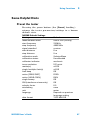
Some Helpful Hints
47
Preset the tester 47
Adjust amplitude scale 48
Using single sweep 48
Enabling interference immunity 48
Quick access to freq/dist setups 49
Connector Care 49
System Setups 55
Setting screen resolution 55
Setting power manager 55
Choosing a unit 55
Setting date and time 56
Firmware upgrade 56
Key light setting 56
Setting the brightness of key light
Light Setting 57
57
36
5
Key Reference
AMPTD
Top
CAL
60
60
62
Bypass Electronic Calibrator
Distance
62
64
Start 64
Stop 64
DTF Config 65
Cable Loss 66
Velocity Factor 66
Cable 67
Window 67
Enter and ESC/CLR
68
Enter 68
ESC/CLR 68
Frequency
69
Start 69
Stop 69
Signal Standard 69
Limit
70
Limit 1 70
Limit 2 70
Limit Beep 71
Marker
72
Marker 1...6 72
Marker All off 73
Meas/View
74
Resolution 74
Single 74
IIM (Interference Immunity) 74
Trace Overlap 75
Mode
System
76
77
Cal Mode 77
Power Manager
Units 77
77
Language 77
Clock 77
Status 78
Self Test 78
E Calib Test 78
Intelligent 78
License key 79
Key Light 79
Key Light Edit 79
Light Set 79
6
Instrument Messages
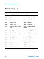
Error Message List
Warning List
7
82
83
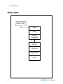
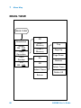
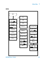
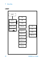
Menu Map
FREQ/DIST
AMPTD
86
87
MEAS/VIEW 88
SYS
89
LIMIT
Marker
90
91
Documentation Conventions:
1. A pair of curly brackets { } indicates a softkey, for example
{Start} refers to the Start softkey.
2. A pair of square brackets [ ] indicates a hardkey,
for example, [ENTER] refers to the ENTER hardkey.
3. “DUT” refers to a device under test.
Agilent N9330B
Handheld Cable & Antenna Tester
1
Overview
#$
1
1 Overview
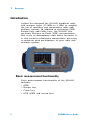
Introduction
Agilent has designed the N9330B handheld cable
and antenna tester (25 MHz to 4 GHz) to simplify
the job of installing and maintaining cable and
antenna systems. In addition to measuring SWR,
Return Loss and Cable Loss, the N9330B also
performs Distance- to- Fault (DTF) measurements
that assist in determining cable defect locations, It
is also useful in identifying maintenance necessary
to maintain peak performance of your cable and
antenna systems.
Basic measurement functionality
Basic measurement functionality of the N9330B
includes:
• SWR
• Return loss
• Cable loss
• DTF (SWR and return loss)
2
N9330B User’s Guide
Overview
1
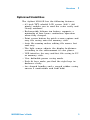
Optimized Usabilities
The Agilent N9330B has the following features:
• 6.5- inch TFT colorful LCD screen (640 × 480
pixels) enables you to read the scans easily and
clearly outdoors.
• Rechargeable lithium- ion battery supports a
minimum of four hours continuous operation
when fully charged.
• Print screen button for quick screen capture and
easy file saving onto the memory stick.
• Auto file naming makes editing file names fast
and easy.
• The light sensor adjusts the display brightness
according to the environment to save power.
• USB interface for easy and fast file saving to PC
or memory stick.
• User definable power saving mode.
• Back- lit keys make you find the right keys in
darkness easily.
• Arc- shaped handles and a rugged rubber casing
ensure a comfortable and firm hold.
N9330B User’s Guide
3
1 Overview
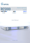
Front Panel Overview
16
15
14
13
12
11
10
N9330B
25 M Hz - 4.0 GHz
Handheld Cable & Antenna Tester
9
F1
F2
PRT SCR
F3
F4
F5
1 ABC
2 DEF
3 GHI
4 JKL
5 M NO
6 PQR
7 STU
8 VWX
9 YZ_
8
7
F6
AU TOSCALE
0 SAVE
RECALL
F7
CAL
6
ESC/ CLR
ENTER
M ODE
FREQ/
DIST
AM PTD
M EAS/
VIEW
SYS
HOLD/
RUN
LIM IT
M ARKER
5
1
1
2
3
4
5
6
7
8
9
10
11
12
13
14
15
16
4
2
3
4
Caption
Standby switch
Function hardkeys
Brief Description
Turns the tester On or Off
Including hardkeys: Mode, FREQ/DIST,
AMPTD, MEAS/VIEW, SYS, Hold/Run,
Limit and Marker
Preset hardkey
Returns the tester to a known state
Enter hardkey
Confirms a selection or configuration
CAL hardkey
Enters a calibration procedure
ESC/CLR hardkey
Escapes from a procedure or clears
characters or numbers
Save and Recall keys For file operation
Auto scale hardkey
Sets the amplitude borders automatically
Print screen hardkey For quick screen capture
Knob
Selects an option or edits a number
Brightness hardkey
Adjusts the screen brightness
Buzzer
Beeps differently on different actions
Light sensor
Adjusts brightness automatically
Softkeys
Indicates current menu functions
Screen
Displays measured traces and status
Strap handle
For hand carry
N9330B User’s Guide
Overview
1
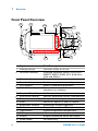
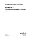
Top Panel Overview
8
23 dBm 50 VDC M AX
RF OUT 50
Ext. Pow er
PC
Charging
11-25 VDC
55 W M AX
1
2
Caption
1 RF Output Connector
(N-type)
2 USB interface Type B
(Host)
3 USB interface Type A
(Device)
4 LED indicator
5 LED indicator (Charging)
6 External DC power
connector
7 LAN interface
8 Tilt Stand (rear of instrument)
N9330B User’s Guide
3
4
5
6
7
Brief Description
Outputs swept signal to DUT
Connects to a PC
Connects to a USB memory stick
Lights (On) when external DC
power is connected to the tester
Lights (On) when the battery is
charging
Connects to external DC power,
for use with either the AC-DC
charger-adapter or automotive
12V DC adapter
Reserved for future expansion
Allows user to lean instrument
back for better viewing when
placed on flat surface
5
1 Overview
Instrument Markings
The CE mark shows that the product complies
with all relevant European Legal Directives
(If accompanied by a year, it signifies when
the design was proven).
The CSA mark is a registered trademark of
the Canadian Standards Association.
N10149
ISM1-A
The C- Tick mark is a registered trademark of
the Australian Spectrum Management Agency.
This symbol is an Industrial Scientific and
Medical Group 1 Class A product (CISPR 11,
Clause 4)
The instruction manual symbol: indicates that
the user must refer to specific instructions in
the manual.
The standby symbol is used to mark a
position of the instrument power switch.
The symbol indicates this product complies
with the
WEEE Directive (2002/96/EC) marking
requirements and you must not discard this
equipment in domestic household waste. Do
not dispose in domestic household waste. To
return unwanted products, contact your local
Agilent office, or refer to
http://www.agilent.com/environment/product/
6
N9330B User’s Guide
Agilent N9330B
Handheld Cable & Antenna Tester
2
Getting Started
#$
7
2 Getting Started
Checking the Shipment
Check the shipment and order list when you
receive the shipment.
• Inspect the shipping container for damages.
Signs of damage may include a dented or torn
shipping container or cushioning material that
indicates signs of unusual stress or compacting.
• Carefully remove the contents from the shipping
container, and verify if the standard accessories
and your ordered options are included in the
shipment.
For any question or problems, contact Agilent
Technologies for consultant and service at:
http://www.agilent.com/find/assist
8
N9330B User’s Guide
Getting Started
2
Safety Considerations
Agilent has designed and tested the N9330B in
accordance with IEC Publication 61010- 1:2001
Safety Requirements for Electrical Equipment for
Measurement, Control and Laboratory Use, and the
tester is supplied in a safe condition. The N9330B
is also designed for use in Installation Category II
and pollution Degree 2 per IEC 61010 and IEC
60664 respectively.
Read the following safety notices carefully before
you start to use this tester set to ensure safe
operation and to maintain the product in a safe
condition.
WA RN ING
WA RN ING
WA RN ING
WA RN ING
Personal injury may result if the tester’s cover is removed.
There are no operator-serviceable parts inside. Always
contact Agilent qualified personnel for service. Disconnect
the product from all voltage sources while it is being
opened.
This product is a Safety Class I tester. The main plug should
be inserted in a power socket outlet only if provided with a
protective earth contact. Any interruption of the protective
conductor inside or outside of the product is likely to make
the product dangerous. Intentional interruption is prohibited.
Electrical shock may result when cleaning the tester with
the power supply connected. Do NOT attempt to clean
internally. Use a clean soft cloth to clean the outside case
only.
Danger of explosion if the battery is incorrectly replaced.
Replace only with the same or equivalent type
recommended.
Do NOT dispose of batteries in a fire. Do NOT place batteries
in the trash. Batteries must be recycled or disposed of
properly.
N9330B User’s Guide
9
2 Getting Started
WA RN ING
CAU
CAU
TI O- N
CAU
CAU
TI O- N
CAU
CAU
TI O- N
CAU
CAU
TI O- N
10
Always use the three-pin AC power cord supplied with this
product. Failure to ensure adequate earth grounding by not
using this cord may cause personal injury and product
damage.
The VxWorks operating system requires full conformity to
USB 1.1 or USB 2.0 standards from a USB disk. Not all the
USB disk are built that way. If you have problems connecting a
particular USB disk, please reboot the analyzer before
inserting the next.
Use USB disk in FAT or FAT32 format, with only one partition
for data saving and loading with the tester.
If left the battery in tester unused, a fully charged battery will
discharge itself over time.
Never use a damaged or worn-out adapter or battery.
The charging process will be intermitted if the battery temperature exceed the safety value. This process will restart when
the temperature declines.
If you are charging the batteries internally, even while the
tester is powered off, the tester may become warm. To avoid
overheating, always disconnect the tester from the AC
adapter before storing the tester into the soft carrying case.
Temperature extremes will affect the ability of the battery to
charge. Allow the battery to attain ambient operating
temperature before use or charging.
Storing a battery in extreme hot or cold places will reduce the
capacity and lifetime of a battery. Battery storage is
recommended at 25 oC.
Always power on the N9330B before connecting an electronic
calibrator.
The average continuous power input is limited not to exceed
+23 dBm, DC voltage to 50 VDC. Instrument damage may
result if these precautions are not followed.
N9330B User’s Guide
Getting Started
2
Environmental Requirements
Agilent technologies has designed this tester for
use under the following conditions:
• Operating temperature:
0 oC to 40 oC (using AC- DC adapter)
–10 oC to +50 oC (using battery)
• Storage temperature: –40 oC to +70 oC
• Battery temperature: 0 oC to 45 oC
• Humidity: 85% + 5%
Electrical Requirements
This tester allows the use of either a lithium
battery pack (internal), AC- DC adapter shipped
with the tester, or optional Automotive +12VDC
adapter for its power supply.
Electrostatic Discharge (ESD) Precautions
This tester was manufactured in an ESD protected
environment. This is because most of the
semiconductor devices used in this tester are
susceptible to damage by static discharge.
Depending on the magnitude of the charge, device
substrates can be punctured of destroyed by
contact or mere proximity of a static charge. The
result can cause degradation of device
performance, early failure, or immediate
destruction. ElectroStatic charges are generated in
numerous ways, such as simple contact, separation
of materials, and normal motions of persons
working with static sensitive devices.
When handling or servicing equipment containing
static sensitive devices, adequate precautions must
be taken to prevent device damage or destruction.
Only those who are thoroughly familiar with
industry accepted techniques for handling static
sensitive devices should attempt to service circuitry
with these devices.
N9330B User’s Guide
11
2 Getting Started
Power Requirements
The AC power supplied must meet the following
requirements:
Voltage:
100 VAC to 240 VAC
Frequency:
47 to 63 Hz
Power:
Maximum 63 W
The AC/DC power supply charger adapter supplied
with the analyzer is equipped with a three- wire
power cord, in accordance with international safety
standards. This power cord grounds the analyzer
cabinet when it is connected to an appropriate
power line outlet. The power cord appropriate to
the original shipping location is included with the
analyzer.
Various AC power cables are available from Agilent
that are unique to specific geographic areas. You
can order additional AC power cords are correct
for use in different areas. The AC Power Cords
table provides a lists of the available AC power
cords, the plug configurations, and identifies the
geographic area in which each cable is typically
used.
The detachable power cord is the product
disconnecting device. It disconnects the main AC
circuits from the DC supply before other parts of
the product. The front- panel switch is only a
standby switch and do not disconnect instrument
from AC LINE power.
12
N9330B User’s Guide
2
Getting Started
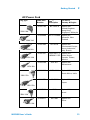
AC Power Cord
Plug Type
Cable Part
Number
8120-1703
Plug a
Description
BS 1363/A
For use in
Country & Region
Option 900
United Kingdom,
Hong Kong,
Singapore, Malaysia
250V 10A
8120-0696
AS 3112:2000 Option 901
Australia, New
Zealand
250V 10A
8120-1692
IEC 83 C4
Option 902
Continental Europe,
Korea, Indonesia,
Italy, Russia
250V 16A
8120-1521
125V 10A
8120-2296
CNS 10917-2 Option 903
/NEMA 5-15P Unite States,
Canada, Taiwan,
Mexico
SEV 1011
Option 906
Switzerland
125V 10A
8120-4600
SABS 164-1
Option 917
South Africa, India
230V 15A
8120-4754
JIS C8303
Option 918
Japan
125V 15A
8120-5181
SI 32
Option 919
Israel
250V 16A
8120-8377
GB 1002
Option 922
China
250V 16A
N9330B User’s Guide
13
2 Getting Started
Working with Batteries
CAU
CAU
TI O- N
Full charge the battery before first using the analyzer.
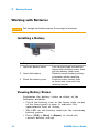
Installing a Battery
Step
1 Open the battery cover
2 Insert the battery
3 Close the battery cover
Notes
Use a phillips type screwdriver,
loosen the retaining screw, then
pull the battery cover open.
Observe correct battery polarity
orientation when installing.
Push the cover closed, then
re-fasten the cover with the
retaining screw.
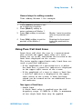
Viewing Battery Status
Determine the battery status in either of the
following methods:
• Check the battery icon in the lower right corner
of the front panel screen: it indicates the
approximate level of charge.
• The LED on the battery indicates the remaining
battery power.
• Press [SYS] > {More} > {Status} to check the
current battery voltage.
14
N9330B User’s Guide
Getting Started
2
Charging a Battery
You may charge the battery both in the tester and
in the external battery charger (option BCG).
CAU
CAU
TI O- N
Connect the automotive adapter to the IT power outlet of your
automobile (with option 1DC) for battery recharging.
You may recharge the battery in the N9330B while
the tester is operating or when it is turned off.
1 Install the battery in the tester.
2 Plug in the correct AC/DC adapter and switch
external power on.
3 The green LED indicating external power and
charging status lights should turn on, indicating
that the battery is charging.
When the battery is fully charged, the green
charging LED turns off.
During charging and discharging, the battery voltage, current, and temperature are monitored. If any
of the monitored conditions exceed their safety
limits, the battery will terminate any further
charging or discharging until the error condition is
corrected.
The charging time for a fully depleted battery, is
approximately four hours.
N9330B User’s Guide
15
2 Getting Started
Your first 10 minutes with the N9330B
The N9330B is fitted with a TFT screen, which is
viewable under all lighting conditions.
CAU
CAU
TI O- N
Do not apply excessive RF or DC signals to the tester RF
OUTPUT connector. The maximum damage RF input level is
+23 dBm (or +50 VDC signal input).
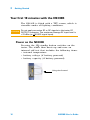
Power on the N9330B
Pressing the
standby button switches on the
tester. The tester then boots up and runs an
internal self- test that includes the following items:
• internal temperature
• battery voltage (if battery powered)
• battery capacity (if battery powered)
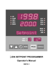
Using the tilt stand
16
N9330B User’s Guide
2
Getting Started
Preparation for Use
Use [SYS] hardkey to set or check the system
settings of the tester.
Setting up the N9330B
Press {Power Manager} to enable or unable the
power saving mode.
Pressing [SYS] > {Power Manager (On)} turns off the
LCD screen and key light after a pre- defined idle
time set by pressing {Power Manager} > {Edit}.
Press [SYS] > {More} > {More} > {Key Light} to turn on
or turn off the key light.
Press [SYS] > {Language} to select a language
displayed on the screen.
Press [SYS] > {Clock} to set the time and date.
Check system status
Pressing [SYS] > {More} > {Status} shows the primary
information and current status of the tester.
Making the first measurement
Four easy steps:
1 Select a measurement mode.
2 Set the desired measurement range, or select a
frequency range from the list of signal standards.
3 Calibrate the tester.
4 Connect the DUT (Device Under Test) to the
tester RF OUT connector being careful not to
apply a signal which exceeds the maximum
signal levels.
Step 1. Selecting a measurement mode
Pressing [MODE] brings up a check box for you to
choose a measurement mode from the following
five modes:
• SWR (Standing Wave Ratio)
N9330B User’s Guide
17
2 Getting Started
• Return loss vs. Frequency
• Cable loss
• DTF- SWR
• DTF- Return loss
Example: selecting the return loss measurement
1 Press [MODE] to bring up the mode selection
check box
2 Use the rotary control knob to select the Return
Loss vs. Frequency
3 Press [ENTER] to confirm your selection.
A measurement mode indicator – FREQ- RL will be
displayed in the top middle part of the screen.
See “Selecting a Measurement Mode" on page 24
for more information.
Step 2. Setting a measurement range
Pressing [FREQ/DIST] brings up a submenu for
setting the measurement range.
If you previously chose a frequency domain
measurement, the submenu allows you to set the
start and stop frequency, or select a pre- defined
frequency range from the list of signal standards.
If you previously chose a DTF measurement, the
submenu allows you to set the start and stop
displayed distance, and other cable measurement
related parameters.
Example: setting a frequency range from 1 GHz to 2 GHz
1 Press {Start} > [1000] > [ENTER] to set the start
frequency to 1 GHz
2 Press {Stop} > [2000] > [ENTER] to set the stop
frequency to 2 GHz
The start frequency of 1000.0 (in MHz) displays at
the left lower corner of screen, and the stop
frequency 2000.0 displays at the right lower corner
of the screen.
18
N9330B User’s Guide
Getting Started
2
Step 3. Calibrating the N9330B
The N9330B must be calibrated before making an
actual measurement (SWR/Return loss/Cable
loss/DTF) using the selected frequency span or the
full span of the instrument. The N9330B offers two
calibration modes:
• FullSpan Cal
Performs an Open- Short- Load calibration across
the full frequency range. The tester allows you to
modify the frequency range for measurement
after the FullSpan Cal is performed.
• SelectedSpan Cal
SelectedSpan calibration is the default calibration
mode. Performs an Open- Short- Load calibration
across a user- defined frequency range. The tester
requires re- calibration if the Selected Frequency
Span is changed.
Key access: [SYS] > {Cal Mode}
Example: Performing a calibration
Assuming the Selected Frequency Span is from
1 to 2 GHz for return loss measurement and the
T- combo calibrator tool is being used.
1 Press [CAL] to bring up a dialog box that will
guide you through the calibration. The normal
calibration order is open, short, and load.
2 Fasten the OPEN end of the T- combo to the RF
OUT connector on the top panel of the tester,
then press [ENTER] to initiate the open
calibration.
3 Fasten the SHORT end of the T- combo to the RF
OUT connector, then press [ENTER] to initiate the
short calibration.
4 Fasten the LOAD end of the T- combo to the RF
OUT connector, then press [ENTER] to initiate the
load calibration.
To abort a calibration, press the [ESC/CLR] button.
For more details of calibration, please refer to
“Calibrate the N9330B before making
measurements" on page 25.
N9330B User’s Guide
19
2 Getting Started
Step 4. Connecting DUT to RF Output port
Example: Measuring return loss
Assuming you have completed the calibration
procedure above. Refer to the following instructions
to make a return loss measurement.
• Connect the cable under test to the RF OUT
connector on the top panel of the tester.
• The tester immediately performs the
measurement and displays a trace on the screen.
If further data analysis is necessary, refer to:
“Using Markers and Pass/Fail Limit Lines" on
page 36, “Processing Traces" on page 39.
20
N9330B User’s Guide
2
Getting Started
Contact Agilent Technologies
Agilent maintains sales and service offices around
the world to provide you with complete support for
your handheld cable and antenna tester. In any
correspondence or telephone conversations, refer to
your handheld cable and antenna tester by its
product number and the full serial number.
Go to http://www.agilent.com/find/assist for help with:
• product selection, configuration, and purchases.
• technical application assistance, and consulting.
• rental options, and refurbished equipment.
• repair, calibration, education and training.
If you do not have access to the internet, call the
appropriate number shown below. Or contact your
local Agilent Technologies Sales and Service Office.
United States
(tel) 800 829 4444
(fax) 800 829 4433
Canada
(tel) 877 894 4414
(fax) 800 746 4866
Latin America
(tel) +1 (305) 269 7500
China
(tel) 800 810 0189
(fax) 800 820 2816
Korea
(tel) 080 769 0800
(fax) 080 769 0900
Japan
(tel) +81 426 56 7832
(fax) +81 426 56 7840
Taiwan
(tel) 0800 047 866
(fax) 0800 286 331
Europe
(tel) +31 20 547 2111
Australia
(tel) 1 800 629 485
(fax) +61 (3) 9210 5947
Other Asia Pacific
Countries
(tel) +65 6375 8100
(fax) +65 6755 0042
Email: [email protected]
N9330B User’s Guide
21
2 Getting Started
22
N9330B User’s Guide
Agilent N9330B
Handheld Cable and Antenna Tester
3
Making Measurements
#$
23
3 Making Measurements
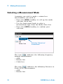
Selecting a Measurement Mode
Assuming you wish to make a return loss
measurement, you need to:
• Press the [MODE] hardkey to call up the mode
selection check box.
• Use the front- panel knob to select a
measurement type from the Mode Select list.
• Press the [ENTER] hardkey to confirm your
selection.
Selecting “Return Loss”
measurement
The icon
indicates the following frequency
domain measurement:
• SWR
• Return loss
• Cable loss
The icon
indicates the following Distance to
Fault (DTF) measurement:
• SWR
• Return loss
24
N9330B User’s Guide
3
Making Measurements
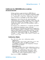
Calibrate the N9330B before making
measurements
Before making a measurement (SWR/Return
loss/Cable loss/DTF) in a specified frequency range
or the full span, you must calibrate your N9330B.
It is important to keep the calibration frequency
range as close as possible to the actual sweep
frequencies necessary for the measurements.
Calibrating over a larger frequency range than the
actual measurement range will reduce the accuracy
of the test results. For example, using a 1 GHz
calibration range when the measurement range is
only few kHz.
Performing one calibration is acceptable provided
the calibration frequency range selected
incorporates all intended measurement frequencies.
If the frequency span is changed, a new calibration
must be performed for that measurement. A new
calibration must be performed if any components
used in the calibration setup are changed. For
example, a short coaxial cable used to connect the
tester to the DUT.
Calibration Mode
The N9330B offers two calibration modes:
• FullSpan Cal
Runs an open- short- load calibration across the
full frequency span (25 MHz to 4 GHz).
A FullSpan Cal ignores the frequency changes
during measurements.
• SelectedSpan Cal
Performs an open- short- load calibration across a
user- defined frequency span. A SelectedSpan Cal
requires a re- calibration of the tester, after
changing the measurement frequency range.
Normally, the selected span should be set as
close to the actual swept frequency range.
Key access: [SYS] > {Cal Mode}
N9330B User’s Guide
25
3 Making Measurements
Types of Calibrators
Two types of calibrator tools are available from
Agilent for use with the tester:
• T-combo calibrator
This is a T- shaped mechanical calibrator. It
consists of a calibrated open, short and 50 Ω
load. Using the T- combo calibrator will result in
a more accurate calibration than when using the
an Electronic calibrator.
• Electronic calibrator
The Electronic calibrator enables you to perform
a one- step calibration process. It automatically
performs an open, short, and 50W load
calibration. The Electronic calibrator is a faster
but less accurate than when using a T- combo
mechanical calibrator.
26
N9330B User’s Guide
3
Making Measurements
Calibrating procedure introduction
Choose either the T- combo or the Electronic
calibrator to perform a calibration process.
Different combinations of calibration mode and
calibrator may benefit the measurement accuracy
differently. (Assuming the measurement resolution
remains unchanged):
• Using SelectedSpan calibration mode and the
T- combo calibrator provides a more accurate
calibration.
• Selecting FullSpan calibration mode and electronic
calibrator is the simplest, most convenient
calibration.
The tester default setting is the SelectedSpan
calibration mode. Agilent recommends using the
SelectedSpan calibration mode for best results.
It is important to keep the calibration frequency
range as close as possible to the actual sweep
frequencies necessary for the measurements.
Calibrating over a larger frequency span than the
actual measurement range will reduce the
accuracy. For example, using a 1 GHz calibration
range when the measurement range is only few
kHz.
Calibrate with an electronic calibrator
NO TE
Never connect an electronic calibrator to the tester until after
powering on the N9330B.
The tester needs about 35 sec. to record the data
of an Electronic calibrator the first time a new
Electronic calibrator is used with a specific tester.
After the initial use of an Electronic calibrator, the
tester requires approximately 12 sec. to perform
the automated open- short- load calibration.
N9330B User’s Guide
27
3 Making Measurements
The Electronic calibrator performs an automatic,
open- short- load consecutively:
1 Press [CAL] to bring up a dialog box for
calibration guidance.
2 Connect the Electronic calibrator to the RF OUT
connector on the top panel of the tester. Connect
the USB cable between the electronic calibrator
and the tester USB port. The correct USB cable
is supplied with an Electronic calibrator.
3 Press [ENTER] to start calibration.
Calibrate with a T-combo calibrator
Using a T- combo calibrator is a three step process
requiring the user to manually change the
open- short- load components. The default order of
the calibration process is open- short- load.
1 Press [CAL] to bring up the dialog box for
calibration guidance.
2 Connect the “Open” component of the T- combo
calibrator to the RF OUT connector of the tester.
Press [ENTER] to start the open calibration.
3 Connect the “Short” component of the T- combo
calibrator to the RF OUT connector of the tester.
Press [ENTER] to start the short calibration.
4 Connect the “Load” component of the T- combo
calibrator to the RF OUT connector of the tester.
Press [ENTER] to start the load calibration.
A “Calibrated” indicator will be displayed on the
upper left corner of the screen when the
calibration is completed.
Using User Cal Mode A User Cal Mode is an optional
selection when using a mechanical calibrator. The
User Cal Mode allows the user to choose one cal
standard from the open- short- load to perform a
customized calibration.
For example, pressing
[CAL] > {User Cal Mode} > {Open} initiates a
calibration using the Open calibration standard
only.
28
N9330B User’s Guide
3
Making Measurements
Measuring Return Loss/SWR/Cable Loss
Return loss is the measurement of the signal
reflection characteristics of a cable and antenna
system. A return loss measurement is useful in
detecting problems in the antenna feedline system
and the antenna itself. A portion of the incident
power is reflected back to the source from
transmission line faults as well as from the
antenna itself. The ratio of the reflected voltage to
the incident voltage is called the reflection
coefficient. The reflection coefficient is a complex
number, meaning it has both magnitude and phase
information. In S- parameter terms, return loss is
referred to as an S11 measurement.
SWR and cable loss measurement derive from
return loss measurement.
NO TE
Test signals can cause interference. When testing cables
attached to an antenna, the test signal is radiated from the
antenna. Verify that the signal used for the test CANNOT
cause interference to other antennas.
Perform a basic return loss measurement
When measuring return loss, SWR, or cable loss
with your N9330B, follow the same operation
procedure as shown below.
To make a return loss (versus. frequency)
measurement over a frequency range of 50 to 400
MHz, perform the following steps:
1 Press the [MODE] hardkey to call up a
measurement mode menu. Rotate the front- panel
knob to select a measurement mode (for this
example, Return Loss). Press the [ENTER] hardkey
to confirm your selection. For more detailed
information, refer to “Selecting a Measurement
Mode" on page 24.
2 Press the {Start} softkey to call up the start
frequency menu. Press {50} > [ENTER] to set the
start frequency to 50 MHz.
N9330B User’s Guide
29
3 Making Measurements
3 Press the {Stop} softkey to call up the stop
frequency menu. Press {400} > [ENTER] to set the
stop frequency to 400 MHz.
4 Press the [CAL] hardkey to call up the calibration
process menu. Follow the instructions for
performing the calibration. For more information
about calibration, refer to “Calibrate the N9330B
before making measurements" on page 25.
A “Calibrated” indicator will be displayed on the
upper left corner of the screen when the
calibration is completed.
5 Remove the calibrator and connect the DUT to
the RF OUT connector of the tester. The tester
will then measure the return loss of the DUT.
Adjusting the measurement resolution
The tester has three resolution settings, 521, 261,
or 131 points. Press the [MEAS/VIEW] hardkey, then
the {Resolution} softkey to choose the resolution
setting desired, then press the [ENTER] hardkey to
enter the selection.
The higher the resolution, the more accurate the
measurement results. However, a higher resolution
setting will require a longer sweep time.
Using Marker/Limit
For further trace analysis, refer to:
“Using markers" on page 36.
“Using Pass/Fail Limit Lines" on page 37
“Trace Operation" on page 39.
For performing an isolated return loss
measurement, refer to:
“Using single sweep" on page 48.
For minimizing the interference, refer to:
“Enabling interference immunity" on page 48.
30
N9330B User’s Guide
Making Measurements
3
Measuring Distance to Fault (DTF)
For this measurement, an internally generated
signal emits from the RF OUT port of the tester
and is transmitted to the cable and antenna system
(DUT). The tester receives and processes the signal
power reflected from faults and imperfections.
In performing a DTF measurement, the tester uses
frequency domain reflectometry. The transmitted
and reflected signals contain information about the
distance to the faults. This information is used to
determine the physical distance to the faults. The
tester displays the physical distance to the
probable faults, corrected for cable loss and the
velocity propagation factor of the cable.
Perform a DTF measurement
To make a DTF- return loss measurement over a
frequency range of 50 to 400 MHz, perform the
following steps:
1 Press [FREQ/DIST] > {Start} > 50 > [ENTER] to set
the start frequency to 50 MHz.
2 Press {Stop} > 400 > [ENTER] to set the stop
frequency to 400 MHz.
3 Press the [MODE] hardkey to select a
measurement mode. Rotate the front- panel knob
to highlight and select the DTF- Return loss, and
press [ENTER] to confirm your selection.
4 Press [CAL] to bring up the calibration process
guidance. Follow the instructions to perform a
calibration. For more information about
calibration, refer to “Calibrate the N9330B before
making measurements" on page 25.
5 Remove the calibrator and connect the cable
under test (DUT) to the RF OUT connector on
the top panel of the tester. The DTF
measurement starts and the results are displayed
on the screen. A peak in the horizontal trace
indicates a defective location.
N9330B User’s Guide
31
3 Making Measurements
For a more precise measurement, enter the cable
loss and velocity factor information.
NO TE
The measured distance and the displayed distance can be
different.
The measured distance refers to the distance the tester has
measured according to the frequency ranges you specified.
You can check the measured distance by pressing
{DTF Config}
The displayed distance refers to that part of the entire
measured distance chosen. The displayed distance may be
manually set by pressing [FREQ/DIST] > {Start}, and {Stop}.
Adjusting the measurement resolution
The tester has three resolution settings, 521, 261,
or 131 points. Press the [MEAS/VIEW] hardkey, then
the {Resolution} softkey to choose the resolution
setting desired, then press the [ENTER] hardkey to
enter the selection.
The higher the resolution, the more accurate the
measurement results. However, a higher resolution
setting will require a longer sweep time.
Using Marker/Limit
For further trace analysis, refer to:
“Using markers" on page 36.
“Using Pass/Fail Limit Lines" on page 37.
“Trace Operation" on page 39.
For getting an isolated return loss signal, refer to:
“Using single sweep" on page 48.
For minimizing the interference, refer to:
“Enabling interference immunity" on page 48.
32
N9330B User’s Guide
Making Measurements
3
Measured distance
It is not always understood how frequency range
affects measured distance and resolution, and may
appears counter- intuitive. This section is intended
to help simplify understanding the DTF
measurement.
In the following equations:
Resolution refers to the number of points that are
measured and used in the displayed trace. Pressing
[MEAS/VIEW] > {Resolution} enables you to change
the resolution setting.
• (Vt/Vc) refers to the velocity factor of a cable, its
transmission rate relative to light. The velocity
factor may be set by pressing {Velo Factor}.
• F2 and F1 refer to the stop and start frequency
(MHz).
The measured distance (in meters) of a DTF
measurement is determined by the following
equation:
Distance= (Resolution x 150 x Vt/Vc) / (F2–F1)
Vc = 3 x 10⁸
From this equation, you can adjust the
measurement:
• To Increase the measured distance:
• Increase the number of points,
or
• Reduce the frequency span.
• To decrease the measured distance:
• Reduce the number of points,
or
• Increase the frequency span.
N9330B User’s Guide
33
3 Making Measurements
34
N9330B User’s Guide
Agilent N9330B
Handheld Cable & Antenna Tester
4
Using Functions
#$
35
4 Using Functions
Using Markers and Pass/Fail Limit Lines
Markers and limit lines are used for measurement
trace analysis.
Using markers
Markers are used to track the specified points on a
trace. You may apply up to six markers and
visually track up to six points on each trace. Each
of the six markers has the following settings:
• On
Activates a Marker and places a vertical, colored
bar, with the Marker number ranging from M1 to
M6 to the foot of the bar.
• Off
Deactivates a marker and erases the Marker bar.
• Edit
Brings up a dialog box and allows you to set the
position of a marker.
NO TE
Rotating the knob will move the position of a marker.
• Marker to Peak
Places the active marker on the highest indicated
value of the trace.
• Marker to Minimum
Places the active marker on the lowest indicated
value of the trace.
• Delta
Is associated with the reference marker (Marker
1 is the default reference marker). Therefore,
Marker 1 must be applied before creating the
delta. Delta displays the value difference between
the reference marker position and the delta
marker position. Only one delta marker can be
associated with a given reference marker.
36
N9330B User’s Guide
4
Using Functions
General steps for adding a marker
Take adding Marker 1 for example:
1
2
3
4
Step
Press [Marker] hardkey to call
up a submenu of markers
Press {Mark 1} softkey to
enter a submenu of Marker 1
Press {On} softkey to activate
Marker 1
Press {Edit} softkey to set the
position of the Marker 1
Note
Marker 1 sets its position
refer to its previous position
Rotating the front-panel
knob also positions the
marker
Using Pass/Fail Limit Lines
Limit lines will alert the user to a measurement
that exceeds the upper limit value of a trace.
Limits are set in dB, and define the location of the
limit lines displayed on the screen.
The tester applies upper limits only. Limit lines are
used as pass/fail indicators:
• If the amplitude of a measured trace is below
the limit line, a green Pass indicator is displayed
in the upper right corner of the screen.
• If the amplitude of a trace is above a limit line,
a red Fail indicator is displayed in the upper
right corner of the screen. A limit fail beep
sound can be turned on for an additional trace
fail indicator.
Two types of limit lines
• Single limit
A single limit value is applied over the full
frequency range, 25 MHz to 4 GHz. A maximum
of two single limit lines may be applied.
N9330B User’s Guide
37
4 Using Functions
• Multiple limit segment
After setting a limit segment, the limit line is
valid only for your selected frequency/distance
range and amplitude range. A maximum of five
limit segments may be applied.
Setting up a limit line
Refer to the following example to add a limit line.
Example: adding limit 1
Step
1 Press [Limit] hardkey to access a
submenu of limit settings.
2 Press {Multi Limit} softkey to
access the multi limit segments
submenu.
3 Press {Limit 1} softkey to access
a submenu of the limit 1.
4 Press {On} softkey to activate a
limit line.
4 Press [Edit] softkey to set the
position of a limit line.
5 Press
{Prev segment/Next segment}
to continue setting specifications
for a multi-limit trace.
38
Note
Use this feature if setting
multiple limit values on a
trace.
choosing the specific
segment number.
This will set the limit line
at previously configured
limit value.
To adjust the limit line to
your specifications.
For multi limit traces.
N9330B User’s Guide
4
Using Functions
Processing Traces
Trace overlap and trace operation are used in the
tester for post trace processing. Very useful in
comparing measurements to identify differences
and faults.
Trace Operation
Trace operation mathematically adds or subtracts
the current measured trace to a previously saved
trace. This will provide information that may
indicate when a cable or antenna system is
degrading in performance and would require
maintenance.i
NO TE
The previously saved trace must have the same setup, with
consistent measurement parameters as the current trace. For
example, the same mode, resolution, and frequency/distance
range.
Example: A saved a trace (data) has been entered
into the local memory of the tester. The trace was
measured under return loss mode in GSM full band
(880 MHz to 960 MHz), with 521 data points.
Perform the following steps for a trace operation:
1 Press [MEAS/VIEW] > {Trace Operation} to access
the check box for selecting a math operation
mode:
• Trace – Memory
Current active trace mathematically subtracts
the trace from local memory of the tester.
• Trace + Memory
Current active trace mathematically adds the
trace from local memory of the tester.
2 Rotate the knob to select a mode and press
[ENTER].
3 The tester brings up a list of existing trace data
in the local memory the tester.
N9330B User’s Guide
39
4 Using Functions
4 Rotate the knob to select a trace that has the
same measurement mode, resolution and
frequency range, and press [ENTER].
The tester displays the mathematically calculated
trace on its screen.
Trace overlap
The tester allows a previously saved trace to be
recalled onto the currently displayed screen. The
two displayed traces are identified by different
colors.
Trace overlap is a real- time tool for quick
comparisons between the current trace and a
previously saved trace. The tester cannot save the
overlaid traces into either local memory or
external USB memory stick.
NO TE
The previously saved trace must have consistent
measurement parameters with the current trace. For example,
the same mode, resolution, and frequency/distance range.
Example: To compare the current measurement
trace to a saved trace (data) in the local memory
of the tester. They were both measured in the
return loss mode, GSM full band (880 MHz to
960 MHz), resolution 521 points.
Perform the following steps to do a trace overlap
operation:
1 Press [MEAS/VIEW] > {Trace Overlap} > {Select Trace}
to display a list of trace data stored in the local
memory of the tester.
2 Use the front- panel knob to select a trace and
press [ENTER].
40
N9330B User’s Guide
Using Functions
4
The tester will display the saved trace, while
continuously making measurement of the DUT
(current measured trace). The two traces are
displayed on the screen simultaneously:
• Trace one is displayed as a static trace and is
green in color. It is the saved trace results
recalled from the local memory of the tester.
• Trace two is yellow in color and is repeatedly
scanned. It is the currently measured trace
result.
N9330B User’s Guide
41
4 Using Functions
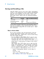
Saving and Recalling a file
N9330B allows you to save trace data, instrument
setups, or the displayed screen graphic information
into the local memory of the tester. With a USB
memory stick inserted, you can also save trace
data and screen copies into an external memory
devices.
File
Format
Max. # (Internal memory)
Trace data
*. data
200
Instrument setting
*.data
15
Screen copy
*.jpg
Stored onto USB disk
Trace data includes both the measurement data
and the instrument setup information. Trace data
and instrument setup files are saved with a “.data”
file extension.
Save a trace data
Trace data includes the measured data and the
current instrument setups. Save Data does not
include limit lines. Limit lines can be saved using
the Save Setup feature.
• Pressing [Save] > {Save Data} allows you to save
the trace data into local memory ONLY. It also
activates the auto file naming editor and
automatically saves the current trace data with a
name that is consecutive to name of the latest
saved file.
This mode does NOT allow you to edit the file
name. For example, if the previously saved file
name is “Chicago_site1”, the current trace data
will be automatically named as “Chicago_site2”.
• Pressing [Save] > {Save Data as} allows you to:
• select a destination where a trace data is
saved:
Local or USB.
• edit a user defined file name.
See “Editing a file name" on page 44.
42
N9330B User’s Guide
Using Functions
4
Save an instrument setup
The tester will save instrument setups to the local
memory. The maximum number of instrument
setups that can be saved is 15.
Pressing [Save] > {Save Setup} saves the current
instrument settings to the tester’s local memory.
The tester will record the following instrument
settings:
• calibration mode
records FullSpan or SelectedSpan calibration
mode.
• measurement mode
records measurement modes with their ancroyn:
RL, SWR, CL, DTF- RL, or DTF- SWR.
• parameters
records frequency/distance range, and date and
time. Limit lines, if activated, will be saved using
Save Setup.
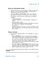
Copy a screen
The Agilent N9330B offers two methods to copy a
screen:
• Press [PRT SCR] to get a quick screen capture
and save the file onto an external USB memory
stick ONLY. Pressing the button also activates
the auto file naming editor and automatically
saves the screen shot with a name that is
auto- sequential to the number of the latest saved
file, from 1 to 65533.
• Pressing [Save] > {Copy Screen} allows you to save
a screen shot into local memory or external USB
memory stick that will be automatically assigned
with a default file name, from 1 to 10.
NO TE
Insert a memory stick into the USB connector before copying
screen.
N9330B User’s Guide
43
4 Using Functions
Both of the methods allow you to save the
currently displayed screen in JPEG format. Each
screen copied is an 8- bit colored, 640 × 480
resolution graph. Copy screen will include any
limit lines, if shown on screen. However, a screen
shot is not editable.
Editing a file name
A valid file name may consist of capitalized letters
(A to Z), decimal numbers (0 to 9), and symbols
(dot and underscore).
Pressing [Save] > {Save Data as} accesses a dialog box
with the last file name used. Press [ESC/CLR] to
erase the current file name, before editing or
creating a new file name.
Input a new file name Use the numerical keypad to
input characters, numbers, and symbols.
• A single press on a numerical button inputs a
decimal number.
• Consecutive press on a numerical button selects
a letter or symbol.
Recall a trace data
To recall a trace data perform the following steps:
1 Pressing [Recall] > {Recall Data} accesses a dialog
box for selecting the trace data to be recalled.
2 Rotate the knob to select a trace data.
3 Press [ENTER] hardkey to confirm the selection.
Trace data can be deleted from the trace data list
in local memory by:
• Press {Delete Trace} softkey to delete a trace data.
• Press {Delete All} to delete all the trace data from
the list.
44
N9330B User’s Guide
Using Functions
4
Recall an instrument setup
The following steps show the steps to recall a
stored instrument setup:
1 Press [Recall] > {Recall Setup} to bring up a dialog
box for selecting which instrument setup is to be
recalled.
2 Rotate the knob to select the desired trace data.
3 Press the [ENTER] hardkey to confirm your
selection.
N9330B User’s Guide
45
4 Using Functions
Viewing system statistics
Check system status
Pressing [SYS] > {More} > {Status} shows the primary
information and current status of the tester,
including:
• mode number, current firmware version, product
serial number, main board serial number, and
option status.
• current calibration mode and status, calibration
temperature range, current internal temperature,
current main battery capacity, and external
power input status.
Running a self test
Pressing [SYS] > {More} > {Self Test} triggers the
tester to run a self test on the following items:
• Temperature
• RTC battery voltage
• RF PLL
• LO PLL
46
N9330B User’s Guide
4
Using Functions
Some Helpful Hints
Preset the tester
Pressing the green button (the [Preset] hardkey)
returns the tester parameters/settings to a known
default state.
N9330B Default Settings
Settings
measurement mode
start frequency
stop frequency
signal standard
start distance
stop distance
calibration mode
calibration status
calibrator indicator
trace resolution
marker(s)
single/multiple limit(s)
limit beep
active [FREQ/DIST]
active [HOLD/RUN]
single sweep
IIM (interference immunity)
velocity factor
windowing
unit
language
date format
N9330B User’s Guide
Default
return loss (vs.freq)
25 MHz
4000 MHz
custom
0m
9m
SelectedSpan
Uncalibrated
mechanic
521 point
all Off
all Off
Off
FREQ
RUN
Off
Off
0.5
none
meter
Depends on previous
language setting
YYYY-MM-DD
47
4 Using Functions
Adjust amplitude scale
Adjusting the amplitude scale can improve the
clarity and view ability of the amplitude of a trace.
the following methods are for adjusting the
amplitude scale:
• Pressing [Auto Scale] hardkey automatically adjust
the amplitude scale to best fit the current trace
view.
• Pressing [AMPTD] > {Top}, or [AMPTD] > {Bottom}
manually set the amplitude scale.
Using single sweep
Using single sweep allows you to get an isolated
return loss signal. In a single sweep, the tester
sweeps from the start to the stop
frequency/distance for only one time, and holds the
trace static.
Key access: [MEAS/View] > {Single}
Enabling interference immunity
Other signals can interfere with Return Loss/SWR
measurement. You can minimize the effect of the
interference on the measurement by activating
interference immunity in the tester.
Key access: [MEAS/VIEW] > {IIM}
NO TE
48
Use of interference immunity increases the measurement
time. Interference immunity should be used if a known
interference signal exists or the Return Loss/SWR
measurement displays suspicious characteristics, such as a
spike or rapid movements in the noise floor.
N9330B User’s Guide
4
Using Functions
Holding a measurement
The user may hold (pause) a measurement.
• Pressing [HOLD/RUN] hardkey pauses (holds) a
measurement, and displays the last trace scan.
• Pressing the [HOLD/RUN] hardkey again will
restart the measurement.
Quick access to freq/dist setups
Pressing [FREQ/DIST] allows the user to quickly
access to frequency or distance setup submenu:
• When the measurement mode is SWR, return
loss or cable loss, pressing [FREQ/DIST] hardkey
accesses a submenu for the frequency range
configuration.
• When the measurement mode is DTF- SWR, or
DTF- return loss, pressing [FREQ/DIST] hardkey
accesses a submenu for distance and DTF
measurement configuration.
Connector Care
Connectors quality is a critical link for a precision
measurement. RF connectors are manufactured to
extremely precise tolerances and must be used and
maintained with care to protect the measurement
accuracy and repeatability.
Taking proper care of cables and connectors will
protect your tester’s ability to make accurate
measurements. Inaccurate measurements often
result of improper connections, dirty, or damaged
connectors.
Worn, damaged, out of tolerance, or dirty
connectors degrade the accuracy and repeatability
of RF measurements.
CAU
CAU
TI O- N
Always take proper electrostatic precautions before
touching the center conductor of any connector, or cable
that is connected to the tester.
N9330B User’s Guide
49
4 Using Functions
Repeatability
If two identical measurements are made with the
tester, the differences in the measured data should
be so small that they do not affect the value of the
measurement. Connector repeatability may be a
cause of poor measurement results. Connector
repeatability problems may be affected by:
• Dirty or damaged connectors
• Connections that have been made without using
proper torque techniques (this applies when
connections to the tester have been removed,
then reconnected).
Extending the life of your cables and connectors
• Minimize the bending of test cables. A single
sharp bend can damage a RF cable.
• Avoid repeated connection and disconnection of
all RF cable connections.
• Do not bend cables at or near the RF
connectors. This may affect the RF performance.
• Inspect all connectors for dirt, nicks, and other
signs of damage or wear before connection. A
bad connector can ruin a good connector
instantly.
• Clean dirty connectors. Dirt and foreign matter
can cause poor electrical connections, affect RF
measurements, and may permanently damage the
connectors.
CAU
CAU
TI O- N
50
Never exceed the recommended connector torque values
when attaching cables or damage may result.
Proper Connector Torque
Connector
Torque
cm-kg
Torque
N-cm
Torque
in-lbs
Type-N
52
508
45
3.5 mm
9.2
90
8
SMA
5.7
56
5
N9330B User’s Guide
Using Functions
4
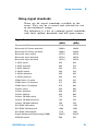
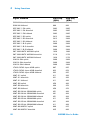
Using signal standards
There are 88 signal standards available in the
tester. They can be accessed and selected for use
in measurement setups.
The following is a list of common signal standards
with their uplink, downlink and full span ranges.
Signal Standard
Start freq.
(MHz)
Stop freq.
(MHz)
Bluetooth US/Europe uplink
2400.0
2484.0
Bluetooth US/Europe downlink
2400.0
2484.0
Bluetooth US/Europe full band
2400.0
2484.0
Bluetooth Japan uplink
2472.0
2497.0
Bluetooth Japan downlink
2472.0
2497.0
Bluetooth Japan full band
2472.0
2497.0
C 450 P uplink
453
464
C 450 P downlink
463
474
C 450 P fullband
453
474
C 450 SA uplink
465
470
C 450 SA downlink
455
460
C 450 SA fullband
455
470
CDMA China 12 uplink
872
915
CDMA China 12 downlink
917
960
CDMA China 12 fullband
872
960
Cellular uplink
824
849
Cellular downlink
869
894
Cellular fullband
824
894
Cellular 700 MHz uplink
776
794
Cellular 700 MHz downlink
746
764
Cellular 700 MHz fullband
746
794
DCS GSM 1800 uplink
1710
1785
DCS GSM 1800 downlink
1805
1880
DCS GSM 1800 fullband
1710
1880
Digital Multimedia Broadcasting (DMB)
2592.5
2692.5
GSM 900 uplink
880
915
N9330B User’s Guide
51
4 Using Functions
52
Signal Standard
Start freq.
(MHz)
Stop freq.
(MHz)
GSM 900 downlink
925
960
GSM 900 fullband
880
960
IEEE 802 11 FH uplink
2402
2495
IEEE 802 11 FH downlink
2402
2495
IEEE 802 11 FH fullband
2402
2495
IEEE 802 11 DS uplink
2412
2484
IEEE 802 11 DS downlink
2412
2484
IEEE 802 11 DS fullband
2412
2484
IEEE 802 11 B G uplink
2400
2484
IEEE 802 11 B G downlink
2400
2484
IEEE 802 11 B G fullband
2400
2484
IMT 2000 UMTS WCDMA uplink
1920
1980
IMT 2000 UMTS WCDMA downlink
2110
2170
IMT 2000 UMTS WCDMA fullband
1920
2170
ISM 2 4 GHz uplink
2400
2484
ISM 2 4 GHz downlink
2400
2484
ISM 2 4 GHz fullband
2400
2484
JTACS/NTAC Japan ARIB uplink
887
925
JTACS/NTAC Japan ARIB downlink
832
870
JTACS/NTAC Japan ARIB fullband
832
925
NMT 411 uplink
411
420
NMT 411 downlink
421
430
NMT 411 fullband
411
430
NMT 450 uplink
450
460
NMT 450 downlink
460
470
NMT 450 fullband
450
470
NMT 450 20 kHz CDMA2000 uplink
451
484
NMT 450 20 kHz CDMA2000 downlink
461
494
NMT 450 20 kHz CDMA2000 fullband
451
494
NMT 450 25 kHz CDMA2000 uplink
411
458
NMT 450 25 kHz CDMA2000 downlink
421
468
NMT 450 25 kHz CDMA2000 fullband
411
468
NMT 900 MATS E uplink
890
915
NMT 900 MATS E downlink
935
960
N9330B User’s Guide
Using Functions
Signal Standard
Start freq.
(MHz)
Stop freq.
(MHz)
NMT 900 MATS E fullband
890
960
PCS GSM 1900 uplink
1850
1910
PCS GSM 1900 downlink
1930
1990
PCS GSM 1900 fullband
1850
1990
PCS Korea uplink
1750
1780
PCS Korea downlink
1840
1870
PCS Korea fullband
1750
1870
PDC 800 uplink
898
940
PDC 800 downlink
843
885
PDC 800 fullband
843
940
PDC 1500 uplink
1525
1549
PDC 1500 downlink
1477
1501
PDC 1500 fullband
1477
1549
PHS uplink
1895
1918
PHS downlink
1895
1918
PHS fullband
1895
1918
SMR 800 uplink
806
821
SMR 800 downlink
851
866
SMR 800 fullband
806
866
SMR 1500 uplink
1453
1465
SMR 1500 downlink
1501
1513
SMR 1500 fullband
1453
1513
TACS/ETACS uplink+C22
872
915
TACS ETACS downlink
917
960
TACSETACS fullband
872
960
Tetra uplink
380
430
Tetra downlink
380
430
N9330B User’s Guide
4
53
4 Using Functions
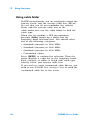
Using cable folder
In DTF measurement, you are required to input the
velocity factor and the average cable loss (dB/m).
In case that you do not remember the velocity
factor and the average cable loss of the
cable- under- test, use the cable folder to find the
cable type.
When you are making a DTF measurement,
pressing {Cable} brings up a dialog box for
frequency band selection first. You should select
any of the following categories:
• Standard (measure in 1000 MHz)
• Standard (measure in 2000 MHz)
• Standard (measure in 2500 MHz)
• Customized cables
Press [ENTER] to confirm the selection. Then the
tester displays a cable list in the frequency band.
Each category of cables is listed with cable type
velocity factor and average cable loss.
If you wish to create customized cable library, you
need to use N9330B Post Analysis Tool to send the
customized cable list to the tester.
54
N9330B User’s Guide
4
Using Functions
System Setups
Setting screen resolution
Three types of screen resolution choices are
available:
• 521
• 261
• 131
The higher resolution you set, the more precise
trace you get, but longer sweep time you need to
spend.
Key access: [MEAS/VIEW] > {Resolution}
Setting power manager
The tester will turn off the LCD screen and key
light after non- use of from 1 minute to 60 minutes,
user defined by pressing {Edit}, if power manager is
turned on.
NO TE
The edited length of time will be noneffective if Power
Manager is set to “off “ that the tester will turn off the display
and lights never after the defined idle time.
Key access: [SYS] > {Power Manager}
Choosing a unit
Two types of distance units are available:
• meter
• foot
Key access: [SYS] > {Units}
The change of unit is displayed at the left lower
corner of the screen.
N9330B User’s Guide
55
4 Using Functions
Setting date and time
Key access: [SYS] > {Clock}
The date and time display on the top line of the
screen.
Firmware upgrade
The N9330B provides an easy and fast access for
firmware update.
NO TE
When updating firmware, make sure there will be a constant
power supply for at least 10 minutes.
Refer to the following steps to upgrade the
firmware:
1 Download firmware upgrade package from
website.
2 Extract and copy N9330B.bin file to the ROOT
directory of USB memory stick.
3 Insert this USB stick to the USB port on the top
panel of N9330B.
4 Press {SYS} > {Upgrade} to upgrade the firmware.
5 Cycle the power to N9330B when notice
“Upgrade Complete. Effective after Restart.”
NO TE
When upgrade N9330B firmware from some old version,
unrecognized fonts will be displayed instead of this message.
please restart N9330B as well.
6 When unit powered on, press
{SYS} > {More} > {Statues} to check the firmware
version.
Key light setting
The key light of the tester can be turned on or be
turned off. The choice is based on personal
preference or using conditions.
Key access: [SYS] > {More} > {Key Light}
56
N9330B User’s Guide
Using Functions
4
Setting the brightness of key light
The user can adjust the brightness of key light.
for different conditions.
Key access: [SYS] > {More} > {More} > {Key Light Edit}
Light Setting
The N9330B offers two brightness adjusting modes.
Addressing “Auto” for adjusting brightness
automatically by the light sensor, while “Man” for
adjusting by manually operation.
Key access:
[SYS] > {More} > {More} > {More} > {Light Set}
N9330B User’s Guide
57
4 Using Functions
58
N9330B User’s Guide
Agilent N9330B
Handheld Cable & Antenna Tester
5
Key Reference
#$
59
5
Key Reference
AMPTD
Sets the displayed amplitude range. Use the
numerical keypad to input the amplitude value or
rotate the knob to increase or decrease the
amplitude value.
The tester saves the previous modified amplitude
range and recalls it when the tester is powered on.
The displayed amplitude range is different when
the tester is in different mode:
• Return loss
In this mode, the default unit dB does not
display on the screen.
• Cable loss
In this mode, the default unit dB does not
display on the screen.
• SWR (Standing Wave Ratio)
• DTF_Return loss
In this mode, the default unit dB does not
display on the screen.
• DTF_SWR
Top
Sets the displayed top amplitude value.
Tester will automatically revise your input by a
minimum amplitude increment, if you previously
input an improper top amplitude.
Key access: [AMPTD] > {Top}
60
N9330B User’s Guide
Key Reference
5
Bottom
Sets the displayed bottom amplitude.
Tester will automatically revise your input by a
minimum amplitude increment, if you previously
input improper bottom amplitude.
Key access: [AMPTD] > {Bottom}
CAU
CAU
TI O- N
Damage to the tester may result when the input power is
greater than +23 dBm or 50 VDC.
N9330B User’s Guide
61
5
Key Reference
CAL
Activates the calibration process for the tester. A
calibration process performs open, short and load
(OSL) calibrations. You can either follow the
instructions from the tester to run a calibration or
customize a calibration.
You can select either an electronic calibrator or a
T- combo mechanical calibrator to perform an
open- short- load calibration.
• T-combo calibrator
Is a T- shaped mechanical calibrator. The three
parts of the T- combo are the open, short and 50
W load. The T- combo calibrator is a more
accurate calibration than the electronic
calibrator and will improve the measurement
range of the tester.
• Electronic calibrator
The electronic calibrator enables you to perform
a one- connection calibration process. It performs
an open, short, and 50 W load calibration
consecutively. The electronic calibrator is faster
but less accurate than the mechanical calibrator.
When a calibration is completed, a “Calibrated”
indicator displays on the left top corner the screen.
Refer to “Calibrate the N9330B before making
measurements" on page 25, for more information.
Bypass Electronic Calibrator
The electronic calibrator is the default setting for
the tester. However, a user may choose to use
either the to electronic calibrator, or T- combo
mechanical calibrator.
When using the T- combo mechanical calibrator, the
user will bypass the default electronic calibrator
process by pressing [CAL] > {Bypass E Calib}. The
tester will then access the manual open- short- load
calibration.
Key access: [CAL] > {Bypass E Calib}
62
N9330B User’s Guide
Key Reference
5
User Cal Mode
The user may define a custom calibration process
instead of using the tester default, open- short- load
combination. Pressing [Cal] > {User Cal Mode} to
select the calibration item for your customized
calibration.
NO TE
User defined calibration accepts only the T- combo
calibrator. The electronic calibrator is not
compatible with any user defined calibration mode.
A User Cal requires the user to perform an
open- short- load calibration process.
Key access: [CAL] > {User Cal Mode}
N9330B User’s Guide
63
5
Key Reference
Distance
When you are using the DTF (Distance to Fault)
mode, pressing [FREQ/DIST] brings up a submenu of
setting DTF parameters, instead of frequency range.
The tester saves the latest defined DTF parameters
and recalls them when you power on the tester
next time.
Start
Sets the displayed start distance. You can
pre- define the default unit to be either meters or
feet by pressing [SYS] > {Units}. The minimum
distance increment is 0.1 m or 0.1 foot.
Key access: {Start}
Stop
Sets the displayed stop distance. Stop distance is
always greater than the start distance. The
maximum stop distance is calculated from the
following equation:
(Resolution * 150 * Vt/Vc) / (F2–F1)
In this equation,
• Resolution means the current resolution of the
trace. Pressing [MEAS/VIEW] > {Resolution} enables
you to select resolution setups: 131, 261 or 521
points.
• Vt /Vc means the velocity factor of a cable.
• Vc means velocity of light.
• F2 means the stop frequency and F1 refers to the
start frequency. The offset between F2 and F1
should always be greater than a tenth of current
resolution (Resolution/10). For example, if the
current resolution is 521, then F2–F1 should be
greater than 52.1 MHz.
Key access: {Stop}
64
N9330B User’s Guide
Key Reference
5
DTF Config
Lists and edits the DTF parameters.
Key access: {DTF Config}
Pressing {DTF Config} brings up a check list, showing
the parameters in a DTF measurement:
• Start Distance
When you rotate knob to highlight this
parameter and press [ENTER], the displayed start
distance becomes editable. This is equivalent to
pressing [FREQ/DIST] > {Start} in DTF mode.
• Stop Distance
When you rotate knob to highlight this
parameter and press [ENTER], the displayed stop
distance becomes editable. This is equivalent to
pressing [FREQ/DIST] > {Stop} in DTF mode.
• Start Frequency
When you rotate knob to highlight this
parameter and press [ENTER], the start frequency
becomes editable. This is equivalent to pressing
[FREQ/DIST] > {Start} when in non- DTF mode.
Changing frequency range changes the maximum
measured and displayed distance.
• Stop Frequency
When you rotate knob to highlight this
parameter and press [ENTER], the stop frequency
becomes editable. This is equivalent to pressing
[FREQ/DIST] > {Stop} when in non- DTF mode.
Changing frequency range changes the maximum
measured and displayed distance. Refer to
“Distance" on page 64, for more information.
• Resolution
When you rotate knob to highlight this
parameter and press [ENTER], the trace resolution
becomes editable. This is equivalent to pressing
[Meas/View] > {Resolution}. Changing the
resolution changes the maximum measured and
displayed distance.
N9330B User’s Guide
65
5
Key Reference
• Windowing
When you rotate knob to highlight this
parameter and press [ENTER], the windowing
menu is presented. This is equivalent to pressing
{Window} in DTF mode.
• Cable
When you rotate knob to highlight this
parameter and press [ENTER], a cable library is
brought up. This is equivalent to pressing {Cable}
in DTF mode.
• Velocity Factor
When you rotate knob to highlight this
parameter and press [ENTER], the velocity factor
becomes editable. This is equivalent to pressing
{Velocity Factor} in DTF mode.
• Cable Loss
When you rotate knob to highlight this
parameter and press [ENTER], the cable loss
becomes editable. This is equivalent to pressing
{Cable Loss} in DTF mode.
Cable Loss
Sets the average loss of a transmission cable, with
minimum increment is 0.001. Use either dB/m or
dB/foot as its unit.
Key access: {Cable Loss}
Velocity Factor
Sets the velocity factor of a transmission cable.
Velocity factor has no unit. It refers to the rate of
a signal’s transmission speed in a particular cable
versus its transmission speed in vacuum. Velocity
factor ranges from 0.01 to 1.
Key access: {Velocity Factor}
66
N9330B User’s Guide
Key Reference
5
Cable
The cable library consists of four categories of
cables:
•
•
•
•
Standard cables below 1000 MHz
Standard cables below 2000 MHz
Standard cables below 2500 MHz
Customized cables
Key access: {Cable}
In each category, commonly used cables are listed
with cable type, velocity factor, and cable loss. If
you need to customize cables, use the N9330B Post
Analysis Tool (PC software) to send customized
cable list to the tester.
Window
• Adds window to traces. Five options of
windowing include:
•
•
•
•
Rectangular windowing
Hamming windowing
3- sample Blackman windowing
4- sample Blackman windowing
• None
Key access: {Window}
N9330B User’s Guide
67
5
Key Reference
Enter and ESC/CLR
[ENTER] and [ESC/CLR] are the frequently used keys
on the tester.
Enter
• Terminates date entry and enters into the
analyzer a numerical value keyed from numeric
keypad on the front panel.
• Terminates filename entries.
Key access: [ENTER]
ESC/CLR
• Clears data entries.
• Exits from a functional block.
Key access: [ESC/CLR]
68
N9330B User’s Guide
Key Reference
5
Frequency
Sets the measurement frequency range. The default
unit is MHz and the tester provides this unit only.
The tester saves the latest defined frequency range
and recalls the frequency setup when you power
on the tester next time.
Start
Sets the start frequency. The minimum increment
is 0.1 MHz. Use numerical keypad to input the
frequency and press [ENTER] to confirm your input.
Or rotate the knob to increase or decrease the
frequency. You can also press {Left} or {Right} to
move the cursor to the digit you want to edit on,
then rotate the knob to modify the value.
Key access: [FREQ/DIST] > {Start}
Stop
Sets the stop frequency. The minimum increment is
0.1 MHz.
Key access: [FREQ/DIST] > {Stop}
Signal Standard
Includes a frequency range list of several signal
standards. When you select a signal standard from
the list, the tester automatically sets the start and
stop frequency according to the frequency of the
signal standard you just selected. Refer to “Using
signal standards" on page 51 for more information.
Key access: [FREQ/DIST] > {Signal Standard}
NO TE
When in DTF mode, pressing [FREQ/DIST] brings up a
submenu of setting the distance range, instead of frequency
range.
N9330B User’s Guide
69
5
Key Reference
Limit
Sets the pass/fail bar for traces. Two individual
single limit lines and single limit line with five
multiple limit segments are selectable. The tester
also provides a limit beep function to alert a
failure of limit judgement. If traces are below a
limit or a limit segments, the tester judges the
measurement as “passed”, if the traces are above
the limit bars, the tester judges the measurement
as “failed”.
Limit 1
Pressing [LIMIT] > {Limit 1} brings up a sub menu for
editing a single limit applied horizontally across
the displayed bandwidth.
The amplitude range of a single limit varies
according to the current measurement mode. Refer
to “AMPTD" on page 60 for more information.
Key access: [LIMIT] > {Limit 1}
Limit 2
Pressing [Limit] > {Limit 2} brings up a sub menu for
editing a single limit that applies a second
horizontal limit line across the displayed
bandwidth.
The amplitude range of a single limit varies
according to the current measurement mode. Refer
to “AMPTD" on page 60 for more information.
Key access: [LIMIT] > {Limit 2}
70
N9330B User’s Guide
Key Reference
5
Multiple Limit
Pressing {Multi Limit} brings up a submenu for
editing multiple limit segments. Up to five
individual limit segments may be applied. Each
segment requires a defined frequency and
amplitude value of the start and end point for the
segment.
NO TE
Limit segments may not overlap with each other and
segments must have a horizontal component, that is. they
cannot be vertical.
Key access: [LIMIT] > {Multi Limit}
Limit Beep
The tester emits a beeping sound when the trace is
above the limit bar to indicate the measurement
fails as defined in the limit setups.
Key access: [LIMIT] > {Limit Beep}
N9330B User’s Guide
71
5
Key Reference
Marker
Provides frequency and amplitude readout for a
particular point or multiple points on a trace. The
tester provides 6 markers, with 6 different colors.
You can turn on or off any one of them, or turn
off all of them at them same time.
Marker readout displays at the lower side of the
screen, in a format of (frequency, amplitude). The
tester always uses MHz as its default frequency
unit and dB as its default amplitude unit except
for SWR measurement.
Marker 1...6
Provides editable markers, labeled from Marker1 to
Marker6. Two methods of placing a marker onto a
particular point on a trace:
• Turn on a marker and rotate the knob to move
the marker to the point.
• Turn on a marker and press [Edit] to manually
set the marker to a specified point.
Key access: [MARKER] > {Marker 1...6} > {Edit}
Delta
Calculates and reads out the frequency and
amplitude offsets of Markers, comparing to
Marker1. When using delta function, the tester
keeps the marker on the trace as it is, but the
readout changes to the frequency and amplitude
offsets comparing to the Marker1.
Key access: [MARKER] > {Marker 2...6} > {Delta}
Marker to Peak
Places a marker to the point that has the highest
amplitude on the trace.
Key access: [MARKER] > {Marker 1...6} > {Marker to Peak}
72
N9330B User’s Guide
Key Reference
5
Marker to Minimum
Places a marker to the point that has the lowest
amplitude on the trace.
Key access:
[MARKER] > {Marker1...6} > {Marker to Minimum}
Marker All off
Turn off all the active markers.
Key access: [MARKER] > {Marker All off}
N9330B User’s Guide
73
5
Key Reference
Meas/View
Five functional blocks are available under
[MEAS/VIEW]:
• Setting the trace resolution
• Enabling the single sweep
• Performing mathematical operation on two traces
• Performing trace overlap comparison
• Enabling interference immunity
Resolution
Three types of trace resolution are selectable:
• 131 points
• 261 points
• 521 points
Key access: [MEAS/VIEW] > {Resolution}
Single
Toggles the single sweep between on and off. When
single sweep is off, the tester sweeps continuously.
Key access: [MEAS/VIEW] > {Single}
IIM (Interference Immunity)
Toggles the interference immunity between on and
off. When IIM is on, the sweep speed becomes
slower than normal.
Key access: [MEAS/VIEW] > {IIM}
74
N9330B User’s Guide
Key Reference
5
Trace Operation
Mathematically compares current trace with a
pre- stored trace. Trace operation requires both
measurements be made using the same parameters,
mode, resolution, and frequency/distance range.
Pressing {Trace Operation} brings up a check box for
you to choose a trace operation mode:
• Off
The tester turns off trace operation function.
• Trace – Memory
Current trace subtracts pre- stored trace.
• Trace + Memory
Current trace adds pre- stored trace.
Key access: [MEAS/VIEW] > {Trace Operation}
Trace Overlap
Overlaps currently displayed measurement trace
with a previously- stored trace, using a different
color. Trace Overlap requires both measurements
be made using the same parameters, mode,
resolution, and frequency/distance range.
Key access: [MEAS/VIEW] > {Trace Overlap}
N9330B User’s Guide
75
5
Key Reference
Mode
Accesses the check box menu for selecting the
measurement mode from the following five options:
• Standing wave ratio (SWR)
• Return loss
• Cable loss
• Distance- to- Fault (DTF)
• Standing wave ratio
• Return loss
Key access: [MODE]
76
N9330B User’s Guide
Key Reference
5
System
Personalizes the tester and manages system setups.
Cal Mode
Toggles calibration mode between full span
calibration and selected span calibration.
Key access: [SYS] > {Cal Mode}
Power Manager
Pressing [SYS] > {Power Manager (on) } enables the
power saving mode. The tester will turn off the
LCD screen and key light after non- use of from
1 minute to 60 minutes, user defined by pressing
[SYS] > {Power Manager} > {Edit}. Pressing any key on
the front panel, except the power switch, brings
the tester back to its previous state immediately.
Key access: [SYS] > {Power Manager}
Units
Toggles the default setting unit of distance between
meter and foot.
Key access: [SYS] > {Units}
Language
Enables you to select a regional language displayed
on the screen. Choices are: English, French,
German, Italian, Spanish, Portuguese, Russian,
Korean, Japanese, Simplified Chinese and
Traditional Chinese.
Key access: [SYS] > {Language}
Clock
Accesses the date and time settings.
Key access: [SYS] > {Clock}
N9330B User’s Guide
77
5
Key Reference
Upgrade
Enables the firmware upgrade process.
1 Copy the upgrade application onto the root level
of a USB memory stick.
2 Insert the USB memory stick into the USB
interface of the tester on its top panel.
3 Press [SYS] > {Upgrade} to initiate firmware
upgrade.
4 The tester will promotes a message to indicate
firmware upgrading is in process.
5 After upgrading completes, power off the tester
then reboot it.
Key access: [SYS] > {Upgrade}
Status
Shows the systematic information of the tester.
Key access: [SYS] > {Status}
Self Test
Runs a self test on temperature and hardware.
Key access: [SYS] > {Self Test}
E Calib Test
Verifies the communication between the electronic
calibrator and the tester.
Key access: [SYS] > {E Calib Test}
Intelligent
Toggles the ability to identify the calibration loads
(Open/Short/Load) from each other between on
and off.
Key access: [SYS] > {Intelligent}
78
N9330B User’s Guide
Key Reference
5
Fast Meas
Toggles the fast sweep between on and off.
Key access: [SYS] > {Fast Meas}
License key
Brings up a window for inputting a license code
for an option.
Key access: [SYS] > {License key}
Key Light
The key light of the tester can be turned on or be
turned off resting with using conditions.
Key access: [SYS] > {Key Light}
Key Light Edit
The brightness of the key light can be adjusted
based on personal preference.
Key access: [SYS] > {Key Light Edit}.
Light Set
The Agilent N9330B provides two brightness
adjusting modes. Addressing “Auto” for adjusting
brightness automatically by the light sensor, while
“Man” for manually operation.
Key access: [SYS] > {Light Set}
N9330B User’s Guide
79
5
80
Key Reference
N9330B User’s Guide
Agilent N9330B
Handheld Cable and Antenna Tester
6
Instrument Messages
#$
81
6 Instrument Messages
Error Message List
Error
Code
Error Message
Description
-310
System error
Failed to write to file.
-311
System error
Failed to load system file.
-312
System error
Failed to delete file.
-313
System error
Failed to read file.
-314
System error
Failed to save file.
525
Read Ext. power voltage
error
Failed to read Ext. power
voltage.
526
RTC battery low voltage
RTC battery Low voltage.
527
Read RTC battery error
Failed to read RTC battery.
528
Read main battery error
Failed to read main battery.
529
Temperature sensor
communication error
Failed to temperature sensor
communication.
530
Read RTC time error
Failed to read RTC time.
531
Read Ecal serial number
error
Failed to read electronic
calibrator serial number.
701
RF PLL error
RF PLL unlocked.
702
LO PLL error
LO PLL unlocked.
703
RF and LO error
RF and LO PLL unlocked.
82
N9330B User’s Guide
Instrument Messages
6
Warning List
No.
Warning Message
1
Open segment error. Overlapped with other segment(s).
Continue in 3 seconds.
2
Open segment error. The start is greater than the stop.
Continue in 3 seconds.
3
Edit segment error. The start is greater than the stop.
Continue in 3 seconds.
4
Edit segment error. Overlapped with other segment(s).
Continue in 3 seconds.
5
Trace operation error. Incompatible traces. Continue in
3 seconds.
6
Trace overlap error. Incompatible traces. Continue in 3
seconds.
7
Edit segment error. Segment cannot be vertical.
Continue in 3 seconds.
8
File name already exists, overwrite it? Press ENTER to
overwrite. Press ESC to abort.
9
File name too long. Max. 20 char allowed. Press
ENTER/ESC to abort.
10
Calibration invalid. Frequency changed. Continue in 3
seconds.
11
Calibration will be invalidated. Temperature out of
range. Press ENTER/ESC to abort.
12
Cannot open segment. Segment cannot be vertical.
Continue in 3 seconds.
13
Save file error. File name cannot be null. Press
ENTER/ESC to abort.
N9330B User’s Guide
83
6 Instrument Messages
84
No.
Warning Message
14
Save trace error. Memory is full. Continue in 3 seconds.
15
Cannot modify the value now Continue in 3 seconds.
16
Changing CAL mode invalidates calibration. Press
ENTER to continue Press ESC to abort.
17
Changing frequency invalidates calibration. Press
ENTER to continue Press ESC to abort.
18
Delete this trace? Press ENTER to continue. Press ESC
to abort.
19
Delete all traces? Press ENTER to continue. Press ESC
to abort.
20
Freq range is changed. BW is below min. BW. Continue
in 3 seconds.
21
Cannot upgrade. There isn't application in the U-disk.
Press ENTER/ESC to abort.
22
Upgrade complete. Press ENTER/ESC to abort.
N9330B User’s Guide
Agilent N9330B
Handheld Cable & Antenna Tester
7
Menu Map
#$
85
7 Menu Map
FREQ/DIST
FREQ/DIST
Start
Stop
Signal
Standard
Home
Page up
Page down
End
86
N9330B User’s Guide
Menu Map
7
AMPTD
AMPTD
Top
Bottom
N9330B User’s Guide
87
7 Menu Map
MEAS/VIEW
MEAS/VIEW
Off
Resolution
Single
ON OFF
Trace
Operation
Trace –
Memory
Top
Trace +
Memory
Page Up
Page Down
Trace
Overlap
On
IIM
ON OFF
Off
Bottom
Delete Trace
Select Trace
Delete All
Return
88
N9330B User’s Guide
Menu Map
7
SYS
SYS
On
Cal Mode
Ful Sel
Off
Power
Manager
Edit
Units
Meter Foot
Return
Language
Status
Clock
Keep Beep
ON OFF
License Opt
Self Test
Upgrade
E Calib Test
More
License Key
Intelligent
ON OFF
Fast Meas
ON OFF
More
Key Light
ON OFF
Key Light
Edit
More
Light Set
Auto Man
Return
N9330B User’s Guide
89
7 Menu Map
LIMIT
LIMIT
On
Limit 1
Off
Limit 2
Edit
Multi Limit
Return
Limit Beep
ON OFF
On
Off
Segment 1
Edit
Segment 2
Return
Segment 3
Segment 4
Segment 5
Return
90
N9330B User’s Guide
Menu Map
7
Marker
Marker
On
Off
Marker 1
Edit
Marker 2
Marker 3
Marker 4
Marker to
Peak
Marker to
Minimum
Return
Marker 5
Marker 6
Marker
All off
On
Off
Edit
Delta
(M2-M1)
Marker to
Peak
Marker to
Minimum
Return
N9330B User’s Guide
91
7 Menu Map
92
N9330B User’s Guide
Index
A
I
Adjusting resolution, 30
Amplitude, scale adjust, 48
Auto scale, 48
IIM, Interference Immunity, 48
Instrument Markings, def., 6
Instrument Messages, 81
Instrument, introduction, 2
ISM1-A, 6
B
Battery, Charging, 15
Battery, installation, 14
Battery, view status, 14
K
C
L
Cable loss, 29
Calibrate, cal tools, 26
Calibrate, intro, 27
Calibrate, using Electronic
calibrator, 27
Calibrate, using T-combo, 28
Calibrating, def., 19
Calibration mode, 25
calibration, freq change, 25
Calibration, span changes, 25
CF Step, 75
Check system, 17
Connector care, 49
Contact Agilent, 21
Copy screen, 43
Light Set, 57
Limit lines, def., 37
Limit lines, save setup, 43
D
Distance, 64
DTF, 2
DTF Config, 65
DTF Measurement, 31
E
Edit, filename, 44
Electrical Requirements, 11
Error Messages, 81, 82
F
Firmware upgrade, 56
Front Panel, overview, 4
Full Span Cal, def., 19
H
Hold, pause measurement, 49
Key Light Setting, 56, 57
M
Making a measurement, 17
Markers
adding, 37
using, 36
Measured distance, def., 33
Measurement mode, 17
Measurement mode, selecting, 24
Measurement range, 18
Measurement, functionality, 2
Measuring DTF, 31
Measuring Return Loss, 29
Menu Map, 85
P
Performing a calibration, 19
Preset, default settings, 47
R
Recall setup, 45
Recall trace data, 44
Reference Level, 60
Resolution, adjusting, 32
Return loss, def., 29
S
Safety Considerations, Warnings, 9
Save setup, instrument, 43
Save trace data, 42
Saving a trace, 42
93
Screen resolution, 55
Selected Span Cal, def., 19
Self test, 46
Settings, Date & Time, 56
signal standards, 51
Span, 79
Status, Check system, 46
Sweep Time, 70
Sweep, single, 48
SWR, 29
System setups, 55
T
Top Panel, overview, 5
Trace Operation, 39
Trace overlap, compare, 40
U
Unit, 55
Using limit lines, 37
V
Velocity Factor, 66
W
Warning, 83
94