1
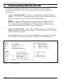
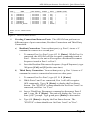
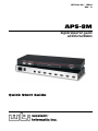
WTI Part No.: 13499
Rev.: A
APS-8M
Asynchronous Port Switch
with Internal Modem
Quick Start Guide
Warnings and Cautions:
Installation Instructions
Secure Racking
If Secure Racked units are installed in a closed or multi-unit rack assembly, they may require further
evaluation by Certification Agencies. The following items must be considered.
1.
The ambient within the rack may be greater than room ambient. Installation should be such
that the amount of air flow required for safe operation is not compromised. The maximum
temperature for the equipment in this environment is 45°C. Consideration should be given to the
maximum rated ambient.
2.
Installation should be such that a hazardous stability condition is not achieved due to uneven
loading.
Input Supply
1.
Check nameplate ratings to assure there is no overloading of supply circuits that could have an
effect on overcurrent protection and supply wiring.
2.
When installing 48 VDC rated equipment, it must be installed only per the following conditions:
A. Connect the equipment to a 48 VDC supply source that is electrically isolated from the
alternating current source. The 48 VDC source is to be connected to a 48 VDC SELV source.
B. Input wiring to terminal block must be routed and secured in such a manner that it is
protected from damage and stress. Do not route wiring past sharp edges or moving parts.
C. A readily accessible disconnect device, with a 3 mm minimum contact gap, shall be
incorporated in the fixed wiring.
Grounding
Reliable earthing of this equipment must be maintained. Particular attention should be given to
supply connections when connecting to power strips, rather than direct connections to the branch
circuit.
No Serviceable Parts Inside; Authorized Service Personnel Only
Do not attempt to repair or service this device yourself. Internal components must be serviced by
authorized personnel only.
• Shock Hazard - Do Not Enter
Disconnect Power
If any of the following events are noted, immediately disconnect the unit from the outlet and contact
qualified service personnel:
1.
If the power cord becomes frayed or damaged.
2.
If liquid has been spilled into the device or if the device has been exposed to rain or water.
APS-8M Asynchronous Port Switch; Quick Start Guide
1.
Introduction
This Quick Start Guide describes a simplified installation procedure for the
APS-8M hardware, which will allow you to communicate with the unit in order
to demonstrate basic features and check for proper operation.
Note that this Quick Start Guide does not provide a detailed description of
unit configuration, or discuss advanced operating features in detail. For more
information, please refer to the APS-8M User’s Guide (WTI P/N 13511), which
can be found on the CDROM included with this Quick Start Guide or at our
online user’s guide archive at http://www.wti.com/guides/guidarch.htm.
2.
Hardware Installation
Apply Power to the APS-8M
Refer to the power rating nameplate on the APS-8M back panel, and then
connect the unit to an appropriate power source. Set the Master Power Switch on
the APS-8M back panel to the ON position.
Connect your Telco Line to the APS-8M
Use a standard RJ-11 cable to connect your Telco outlet to the Line Port, located
on the APS-8M back panel. Note that the unit sees the internal modem as Port 8.
To connect to the Modem Port, use the procedure described in Section 3 of this
Quick Start Guide.
Connect a PC to the APS-8M
Attach a standard null modem cable from your PC COM port to the Port 1
connector on the APS-8M back panel.
Note: When the APS-8M is shipped from the factory, communications
parameters are set as follows: 9600 bps, RTS/CTS Handshaking, 8
Data Bits, One Stop Bit, No Parity. Although the APS-8M allows
these parameters to be easily redefined, for this Quick Start procedure,
it is recommended to configure your communications program (e.g.
HyperTerminal) to accept the default parameters.
Connect your Equipment to the Serial Ports
Use an appropriate DB9 cable to connect the RS232 Serial Port on your
equipment to the desired Serial Port on the APS-8M
• PCs and other DTE Devices: Use a standard null modem cable.
• External Modems and other DCE devices: Use a standard serial
modem cable.
Page 3
APS-8M Asynchronous Port Switch; Quick Start Guide
3.
Communicating with the APS-8M
The APS-8M command mode allows you to check unit status, change
configuration parameters and connect and disconnect ports (including the
Modem Port.)
1.
Access Command Mode: Start your communications program and press
[Enter]. The "APS>" Command prompt should appear, indicating that you
have successfully accessed the APS-8M command mode.
Note: If a password that permits access to Supervisor Mode has been
previously defined, a prompt will be displayed. Key in a Supervisor
Level password, and press [Enter]. If a Supervisor Level password has
not yet been defined, the prompt will not be displayed.
2.
Review the Help Menu: At the APS Command Prompt, type /H and press
[Enter] to display the Help Menu (Figure 1), which provides a basic listing
of all APS-8M commands.
3.
Port Status Screen: Type /S and press [Enter] to display the Port Status
Screen (Figure 2), which summarizes conditions at all APS-8M ports.
COMMAND MENU:
DISPLAY
/S
/SD
/W [n]
/J
/H
/V
Port Status
Port Diagnostics
Port Parameters (Who)
Site ID
Command Menu (Help)
View Password Directory
CONTROL
<Enter>
/X
/C <n> [n]
/D <n | ... | *>
/E <n | ... | *>
/U
/UL
Enter Command Mode
Exit Command Mode
Connect - Local [Remote]
Disconnect Port(s)
Erase Buffer
Send Parameter File
Unlock Invalid Access
CONFIGURATION
/F
System Parameters
/P [n]
Port Parameters
/I
Default and Test
/UF
Upgrade Firmware
/CP
Copy Port Parameters
+--------------------+
| n
Port# or name |
| *
“all”
|
| |
“or”
|
| <> Required entry |
| [] Optional entry |
+--------------------+
/D, /E, /I commands: add /Y to bypass “Sure (y/n)?”
APS>
Figure 1: The Help Screen
Page 4
APS-8M Asynchronous Port Switch; Quick Start Guide
PORT STATUS: APS-M, Version 3.0, Site ID: (undefined)
PORT |
NAME
| CMD ACCESS | STATUS | MODE | BUFFER COUNT
-----+------------------+------------+--------+--------+-------------01 | (undefined)
| Unlocked | Free | Any
|
0
02 | (undefined)
| Unlocked | Free | Any
|
0
03 | (undefined)
| Unlocked | Free | Any
|
0
04 | (undefined)
| Unlocked | Free | Any
|
0
05 | (undefined)
| Unlocked | Free | Any
|
0
06 | (undefined)
| Unlocked | Free | Any
|
0
07 | (undefined)
| Unlocked | Free | Any
|
0
08 | Internal_Modem
| Unlocked | Free | Modem |
0
Enter /H for command menu.
APS>
Figure 2: The Port Status Screen
4.
Creating Connections Between Ports: The APS-8M can perform two
different types of port connections; Resident Connections and Third Party
Connections.
a)
b)
Resident Connection: Your resident port (e.g. Port 1) issues a /C
command to connect to a second port.
i.
To connect Port 1 to Port 2, type /C 2 [Enter]. While Port 1 is
connected, the APS-8M will not recognize commands issued at
Port 1. However, the unit will recognize a Resident Disconnect
Sequence issued at Port 1 or Port 2.
ii.
Issue the Resident Disconnect Sequence (Logoff Sequence); type
^X (press [Ctrl] and [X] at the same time).
Third Party Connection: Your resident port (e.g. Port 1) issues a /C
command to create a connection between two other ports.
i.
To connect Port 2 to Port 3, type /C 2 3 [Enter].
ii.
While Ports 2 and 3 are connected, Port 1 will still recognize
APS commands. Type /S [Enter] to display the Port Status
Screen. The "STATUS" column should now list Ports 2 and 3 as
connected, and Port 1 as "Free".
iii. Issue a Third Party Disconnect command to disconnect Ports 2
and 3; type /D 2 [Enter]. The unit will display the "Are you
Sure (y/n)?" prompt. Type y and press [Enter] to disconnect.
iv.
Type /S [Enter] to display the Port Status Screen. The
"STATUS" column should now list Ports 2 and 3 as "Free".
Page 5
APS-8M Asynchronous Port Switch; Quick Start Guide
5.
Exit Command Mode: At the "APS>" command prompt, type /X and
press [Enter]. The APS-8M will exit command mode.
6.
Access Command Mode via Modem: From a PC with a modem and Telco
line, dial the number for the line which is connected to the
APS-8M’s internal modem. Once the connection is established, the unit
should send the "APS>" command prompt, indicating that you have
successfully accessed command mode.
Note: If a password that permits access to Supervisor Mode has been
previously defined, a prompt will be displayed. Key in a Supervisor
Level password, and press [Enter]. If a Supervisor Level password has
not yet been defined, the prompt will not be displayed.
a)
Type /H and press [Enter] to display the Help Menu. If desired, you
may also wish to repeat the Port Connection / Disconnection examples
described in Step 4 above.
b)
When you have finished communicating with the APS-8M unit, type
/X and press [Enter] to exit command mode and terminate the modem
connection to the unit.
This completes the Quick Start Guide for the APS-8M. Prior to placing the
unit into operation, it is recommended to refer to the APS-8M User’s Guide for
important information regarding advanced configuration capabilities and more
detailed operation instructions. If you have further questions regarding the IPS
unit, please contact WTI Customer Support as described in the User’s Guide.
Page 6
APS-8M Asynchronous Port Switch; Quick Start Guide
FCC Part 15 Regulation
This equipment has been tested and found to comply with the limits for a Class A digital device,
pursuant to part 15 of the FCC Rules. These limits are designed to provide reasonable protection
against harmful interference when the equipment is operated in a commercial environment. This
equipment generates, uses, and can radiate radio frequency energy and, if not installed and used in
accordance with the instruction manual, may cause harmful interference to radio communications.
Operation of this equipment in a residential area is likely to cause harmful interference in which case
the user will be required to correct the interference at his own expense.
This device complies with part 15 of the FCC Rules. Operation is subject to the following two
conditions: (1) This device may not cause harmful interference, and (2) this device must accept any
interference received, including interference that may cause undesired operation
WARNING: Changes or modifications to this unit not expressly approved by the
party responsible for compliance could void the user’s authority to operate the
equipment
EMC, Safety, and R&TTE Directive Compliance
The CE mark is affixed to this product to confirm compliance with the following European
Community Directives:
• Council Directive 89/336/EEC of 3 May 1989 on the approximation of the laws of Member
States relating to electromagnetic compatibility;
and
• Council Directive 73/23/EEC of 19 February 1973 on the harmonization of the laws of
Member States relating to electrical equipment designed for use within certain voltage limits;
and
• Council Directive 1999/5/EC of 9 March on radio equipment and telecommunications terminal
equipment and the mutual recognition of their conformity.
Industry Canada
This Class A digital apparatus complies with Canadian ICES-003.
Cet appareil numérique de la classe A est conforme à la norme NMB-003 du Canada.
This product meets the applicable Industry Canada technical specifications
The Ringer Equivalence Number is an indication of the maximum number of devices allowed to be
connected to a telephone interface. The termination on an interface may consist of any combination
of devices subject only to the requirement that the sum of the RENs of all the devices does not exceed
five
Page 7
5 Sterling • Irvine • California 92618
(949) 586-9950 • Toll Free: 1-800-854-7226
Fax: (949) 583-9514 • http://www.wti.com