1
WTI Part No. 13511
Rev. B
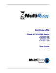
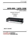
APS-8M / APS-16M
Asynchronous Port Switches
with Internal Modem
Firmware Version 4.x
Models Covered:
APS-8M
APS-8M-DC
APS-16M
APS-16M-DC
User’s Guide
Warnings and Cautions:
INSTALLATION INSTRUCTIONS
Secure Racking
If Secure Racked units are installed in a closed or multi-unit rack assembly,
they may require further evaluation by Certification Agencies. The following
items must be considered.
1.
The ambient within the rack may be greater than room ambient.
Installation should be such that the amount of air flow required for
safe operation is not compromised. The maximum temperature for the
equipment in this environment is 45°C. Consideration should be given to
the maximum rated ambient.
2.
Installation should be such that a hazardous stability condition is not
achieved due to uneven loading.
Input Supply
1. Check nameplate ratings to assure there is no overloading of supply
circuits that could have an effect on overcurrent protection and supply
wiring.
2.
When installing 48 VDC rated equipment, it must be installed only per
the following conditions:
A.
Connect the equipment to a 48 VDC supply source that is electrically
isolated from the alternating current source. The 48 VDC source is
to be connected to a 48 VDC SELV source.
B.
Input wiring to terminal block must be routed and secured in such
a manner that it is protected from damage and stress. Do not route
wiring past sharp edges or moving parts.
C.
A readily accessible disconnect device, with a 3 mm minimum
contact gap, shall be incorporated in the fixed wiring.
Grounding
Reliable earthing of this equipment must be maintained. Particular attention
should be given to supply connections when connecting to power strips, rather
than direct connections to the branch circuit.
i
APS-8M / APS-16M Asynchronous Port Switches; User’s Guide
No Serviceable Parts Inside;
Authorized Service Personnel Only
Do not attempt to repair or service this device yourself. Internal components
must be serviced by authorized personnel only.
• Shock Hazard - Do Not Enter
Disconnect Power
If any of the following events are noted, immediately disconnect the unit from
the outlet and contact qualified service personnel:
ii
1.
If the power cord becomes frayed or damaged.
2.
If liquid has been spilled into the device or if the device has been exposed
to rain or water.
Table of Contents
1.
Introduction . . . . . . . . . . . . . . . . . . . . . . . . . . . . . . . . . . . . . . . . . . . . . . . . . . . . . . . . . . 1-1
2.
Unit Description . . . . . . . . . . . . . . . . . . . . . . . . . . . . . . . . . . . . . . . . . . . . . . . . . . . . . . . 2-1
2.1. Front Panel . . . . . . . . . . . . . . . . . . . . . . . . . . . . . . . . . . . . . . . . . . . . . . . . . . . . . . . 2-1
2.2. Back Panel . . . . . . . . . . . . . . . . . . . . . . . . . . . . . . . . . . . . . . . . . . . . . . . . . . . . . . . 2-2
3.
Getting Started . . . . . . . . . . . . . . . . . . . . . . . . . . . . . . . . . . . . . . . . . . . . . . . . . . . . . . . .
3.1. Hardware Installation . . . . . . . . . . . . . . . . . . . . . . . . . . . . . . . . . . . . . . . . . . . . . . .
3.2. Connect your Equipment to the Serial Ports . . . . . . . . . . . . . . . . . . . . . . . . . . . . .
3.3. Communicating with the APS-8/16M . . . . . . . . . . . . . . . . . . . . . . . . . . . . . . . . . .
3-1
3-1
3-1
3-2
4.
Hardware Installation . . . . . . . . . . . . . . . . . . . . . . . . . . . . . . . . . . . . . . . . . . . . . . . . . .
4.1. Connecting Power to the APS Unit . . . . . . . . . . . . . . . . . . . . . . . . . . . . . . . . . . . .
4.1.1. AC Powered Units . . . . . . . . . . . . . . . . . . . . . . . . . . . . . . . . . . . . . . . . . .
4.1.2. DC Powered Units . . . . . . . . . . . . . . . . . . . . . . . . . . . . . . . . . . . . . . . . . .
4.2. Connect a Telco Line to the Modem Port . . . . . . . . . . . . . . . . . . . . . . . . . . . . . . .
4.3. Connecting Devices to the APS Serial Ports . . . . . . . . . . . . . . . . . . . . . . . . . . . . .
4-1
4-1
4-1
4-1
4-2
4-2
5.
Configuration . . . . . . . . . . . . . . . . . . . . . . . . . . . . . . . . . . . . . . . . . . . . . . . . . . . . . . . . . 5-1
5.1. Access to the APS-8/16M Command Mode . . . . . . . . . . . . . . . . . . . . . . . . . . . . . 5-1
5.2. System SetUp Ports . . . . . . . . . . . . . . . . . . . . . . . . . . . . . . . . . . . . . . . . . . . . . . . . 5-2
5.3. Password Functions . . . . . . . . . . . . . . . . . . . . . . . . . . . . . . . . . . . . . . . . . . . . . . . . 5-2
5.4. The System Parameters Menu . . . . . . . . . . . . . . . . . . . . . . . . . . . . . . . . . . . . . . . . 5-3
5.4.1. The Password Directory . . . . . . . . . . . . . . . . . . . . . . . . . . . . . . . . . . . . . . 5-5
5.4.2. The Dial Back Function . . . . . . . . . . . . . . . . . . . . . . . . . . . . . . . . . . . . . . 5-8
5.5. Port Configuration . . . . . . . . . . . . . . . . . . . . . . . . . . . . . . . . . . . . . . . . . . . . . . . . 5-10
5.5.1. Configuration Conventions . . . . . . . . . . . . . . . . . . . . . . . . . . . . . . . . . . 5-10
5.5.2. Port Modes . . . . . . . . . . . . . . . . . . . . . . . . . . . . . . . . . . . . . . . . . . . . . . . 5-11
5.5.3. RS232 Port Configuration Menus . . . . . . . . . . . . . . . . . . . . . . . . . . . . . 5-12
5.5.4. The Invalid Access Lockout Feature . . . . . . . . . . . . . . . . . . . . . . . . . . . 5-17
5.6. Copying Parameters to All Ports . . . . . . . . . . . . . . . . . . . . . . . . . . . . . . . . . . . . . 5-18
5.7. Save User Selected Parameters . . . . . . . . . . . . . . . . . . . . . . . . . . . . . . . . . . . . . . 5-19
6.
The Internal Modem . . . . . . . . . . . . . . . . . . . . . . . . . . . . . . . . . . . . . . . . . . . . . . . . . . . 6-1
6.1. Communicating with the Internal Modem . . . . . . . . . . . . . . . . . . . . . . . . . . . . . . . 6-1
6.2. Common AT Commands . . . . . . . . . . . . . . . . . . . . . . . . . . . . . . . . . . . . . . . . . . . . 6-2
7.
The Status Screens . . . . . . . . . . . . . . . . . . . . . . . . . . . . . . . . . . . . . . . . . . . . . . . . . . . . .
7.1. The Port Status Screen (/S) . . . . . . . . . . . . . . . . . . . . . . . . . . . . . . . . . . . . . . . . . .
7.2. The Port Diagnostics Screen (/SD) . . . . . . . . . . . . . . . . . . . . . . . . . . . . . . . . . . . .
7.3. The Port Parameters Screens (/W) . . . . . . . . . . . . . . . . . . . . . . . . . . . . . . . . . . . .
7.4. The Password Directory Screen (/V) . . . . . . . . . . . . . . . . . . . . . . . . . . . . . . . . . .
7-1
7-1
7-2
7-4
7-4
8.
Operation . . . . . . . . . . . . . . . . . . . . . . . . . . . . . . . . . . . . . . . . . . . . . . . . . . . . . . . . . . . .
8.1. Any-to-Any Mode . . . . . . . . . . . . . . . . . . . . . . . . . . . . . . . . . . . . . . . . . . . . . . . . .
8.1.1. Port Connection and Disconnection. . . . . . . . . . . . . . . . . . . . . . . . . . . . .
8.1.2. Defining Hunt Groups . . . . . . . . . . . . . . . . . . . . . . . . . . . . . . . . . . . . . . .
8.2. Passive Mode . . . . . . . . . . . . . . . . . . . . . . . . . . . . . . . . . . . . . . . . . . . . . . . . . . . . .
8.3. Buffer Mode . . . . . . . . . . . . . . . . . . . . . . . . . . . . . . . . . . . . . . . . . . . . . . . . . . . . . .
8.3.1. Reading Data from Buffer Mode Ports . . . . . . . . . . . . . . . . . . . . . . . . . .
8.3.2. Port Buffers . . . . . . . . . . . . . . . . . . . . . . . . . . . . . . . . . . . . . . . . . . . . . . .
8.4. Modem Mode . . . . . . . . . . . . . . . . . . . . . . . . . . . . . . . . . . . . . . . . . . . . . . . . . . . . .
8-1
8-1
8-1
8-4
8-6
8-6
8-7
8-8
8-8
iii
APS-8M / APS-16M Asynchronous Port Switches; User’s Guide
9.
Saving and Restoring Configuration Parameters . . . . . . . . . . . . . . . . . . . . . . . . . . . . 9-1
9.1. Sending Parameters to a File . . . . . . . . . . . . . . . . . . . . . . . . . . . . . . . . . . . . . . . . . 9-1
9.2. Restoring Saved Parameters. . . . . . . . . . . . . . . . . . . . . . . . . . . . . . . . . . . . . . . . . . 9-2
10. Upgrading APS-8/16M Firmware . . . . . . . . . . . . . . . . . . . . . . . . . . . . . . . . . . . . . . . . 10-1
11. Command Reference Guide. . . . . . . . . . . . . . . . . . . . . . . . . . . . . . . . . . . . . . . . . . . . . .11-1
11.1. Command Conventions . . . . . . . . . . . . . . . . . . . . . . . . . . . . . . . . . . . . . . . . . . . . 11-1
11.2. Command Response . . . . . . . . . . . . . . . . . . . . . . . . . . . . . . . . . . . . . . . . . . . . . . . 11-2
11.3. Command Summary . . . . . . . . . . . . . . . . . . . . . . . . . . . . . . . . . . . . . . . . . . . . . . 11-3
11.4. Command Set . . . . . . . . . . . . . . . . . . . . . . . . . . . . . . . . . . . . . . . . . . . . . . . . . . . . 11-4
Appendices
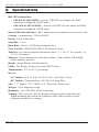
A.
RS232 Port Interface . . . . . . . . . . . . . . . . . . . . . . . . . . . . . . . . . . . . . . . . . . . . . . . . . Apx-1
B.
Specifications . . . . . . . . . . . . . . . . . . . . . . . . . . . . . . . . . . . . . . . . . . . . . . . . . . . . . . . . Apx-2
C.
Customer Service . . . . . . . . . . . . . . . . . . . . . . . . . . . . . . . . . . . . . . . . . . . . . . . . . . . . Apx-3
D.
Trademark and Copyright Information . . . . . . . . . . . . . . . . . . . . . . . . . . . . . . . . . . Apx-4
E.
Regulatory Statements . . . . . . . . . . . . . . . . . . . . . . . . . . . . . . . . . . . . . . . . . . . . . . . . Apx-5
Index . . . . . . . . . . . . . . . . . . . . . . . . . . . . . . . . . . . . . . . . . . . . . . . . . . . . . . . . . . . . . . . . . .Index-1
List of Figures
2.1.. . Instrument Front Panel (Model APS-8M) . . . . . . . . . . . . . . . . . . . . . . . . . . . . . . . . . . . . 2-1
2.2.. . Instrument Front Panel (Model APS-16M) . . . . . . . . . . . . . . . . . . . . . . . . . . . . . . . . . . . 2-1
2.3.. . Instrument Back Panel (Model APS-8M) . . . . . . . . . . . . . . . . . . . . . . . . . . . . . . . . . . . . 2-2
2.4.. . Instrument Back Panel (Model APS-16M) . . . . . . . . . . . . . . . . . . . . . . . . . . . . . . . . . . . 2-2
3.1.. . The Port Status Screen (Model APS-8M Shown) . . . . . . . . . . . . . . . . . . . . . . . . . . . . . 3-3
4.1.. . Terminal Block Assembly (DC Units Only) . . . . . . . . . . . . . . . . . . . . . . . . . . . . . . . . . . 4-1
5.1.. . The System Parameters Menu (/F) . . . . . . . . . . . . . . . . . . . . . . . . . . . . . . . . . . . . . . . . . 5-4
5.2.. . The Edit Password Directory Menu . . . . . . . . . . . . . . . . . . . . . . . . . . . . . . . . . . . . . . . . 5-5
5.3.. . The Add Name/Password Menu (Defaults Shown) . . . . . . . . . . . . . . . . . . . . . . . . . . . . 5-6
5.4.. . The Edit/Delete Name/Password Menu (Sample Values Shown) . . . . . . . . . . . . . . . . . 5-7
5.5.. . Port Configuration Menu (Port 1 Shown) . . . . . . . . . . . . . . . . . . . . . . . . . . . . . . . . . . . 5-12
5.6.. . Port Parameters Menu; Modem Mode (Port 3 Shown). . . . . . . . . . . . . . . . . . . . . . . . . 5-14
5.7.. . The Copy Port Parameters Menu . . . . . . . . . . . . . . . . . . . . . . . . . . . . . . . . . . . . . . . . . 5-18
7.1.. . The Port Status Screen (Model APS-8M Shown) . . . . . . . . . . . . . . . . . . . . . . . . . . . . . . 7-1
7.2.. . The Port Diagnostics Screen (Model APS-8M; Defaults Shown) . . . . . . . . . . . . . . . . . 7-3
7.3.. . The Port Parameters Screen (Port 1 Shown) . . . . . . . . . . . . . . . . . . . . . . . . . . . . . . . . . . 7-4
7.4.. . The Password Directory Screen (Sample Values Shown) . . . . . . . . . . . . . . . . . . . . . . . 7-5
A.1. . RS232 Port Hardware . . . . . . . . . . . . . . . . . . . . . . . . . . . . . . . . . . . . . . . . . . . . . . . . . Apx-1
iv
1. Introduction
WTI’s APS-8M and APS-16M Asynchronous Port Switches allow reliable,
high-speed connections between PCs, modems, and other devices using
dissimilar baud rates, parity, and flow control. The APS-8M and APS-16M
support communication at speeds up to 115.2 Kbps, and feature full RTS/CTS
hardware handshaking and a 33.6K V.34 internal modem. Lightening-swift
data throughput and full flow control make the APS-8M and APS-16M the
perfect data switches for today’s high speed communications applications.
Versatile Connectivity
Up to fifteen different devices can be connected to the APS-16M without the
need to select a common baud rate or parity; up to seven different devices
can be connected to the APS-8M. Each port can be individually configured
for specific baud rates, parity, handshaking, and various other parameters and
options.
Easy Set-Up and Operation
Configuration of the APS-8M and APS-16M is simple. A menu system is used
to select communications parameters, and enable or disable options. The
APS-8M and APS-16M can easily adapt to the requirements of almost any data
communications application.
Password Protected Connection and Command Access
The APS-8M and APS-16M provide two levels of user security; the Supervisor
level and the Non-Supervisor level. The Supervisor level, which is intended
for use by system managers and other administrators, provides complete
access to all port connection / disconnection functions, operating features and
configuration menus, and also allows access to any port on the switch. The
Non-Supervisor level is ideal for collocation applications, since users are only
permitted to view status and connect to the ports allowed by their password.
Internal Modem
The APS-8M and APS-16M feature 33.6K v.34 Internal modems; allowing
easy, convenient out-of-band access to configuration and control functions.
Non-Volatile Memory
If power to the unit is lost or interrupted, the units' non-volatile memory will
retain user-defined parameters and port connections.
1-1
APS-8M / APS-16M Asynchronous Port Switches; User’s Guide
Modem Communication
The APS-8M and APS-16M can both be controlled by a local PC that
communicates with the unit via cable, or controlled remotely via external
modem. Hyperterminal (or another communications program) is used to send
commands to connect ports or display status.
Configuration Backup
Once you have configured the APS-8M or APS-16M to fit your application,
parameters and options can be saved to an ASCII text file on your PC. This
allows you to quickly restore user-selected parameters if the unit configuration
is accidentally altered or deleted. Saved parameters can also be uploaded to
other APS-8M or APS-16M units. This allows rapid set-up when several units
will be configured with identical or similar parameters.
APS-8M and APS-16M Units
This User's Guide discusses both the APS-8M and APS-16M. Throughout
this User's Guide, both units are referred to as "APS-8/16M." The APS-8M
includes seven RS232 ports and an internal modem, and the APS-16M includes
sixteen RS232 ports and an internal modem. All other features function
identically.
Typographic Conventions
Throughout this manual, typefaces and characters have been used to denote the
following:
^ (e.g. ^X)
Indicates a control character. For example, the text
"^X" (Control X) indicates the [Ctrl] key and the
[X] key must be pressed simultaneously.
COURIER FONT Indicates characters typed on the keyboard.
For example, /E or /P 02.
1-2
[Bold Font]
Text set in bold face and enclosed in square brackets,
indicates a specific key. For example, [Enter] or [Esc].
< >
Indicates required keyboard entries.
For Example: /P <n>.
[ ]
Indicates optional keyboard entries.
For Example: /W [n].
2. Unit Description
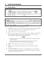
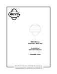
2.1. Front Panel
Figure 2.1: Instrument Front Panel (Model APS-8M)
Figure 2.2: Instrument Front Panel (Model APS-16M)
CLEAR: Restarts the APS-8/16M operating program without changing
user-selected parameter settings or breaking port connections.
ON: Lights when AC Power is applied.
SET: Used to Initialize the APS-8/16M to factory defaults. To initialize,
press and hold both the SET and CLEAR buttons, release only the
CLEAR button, and then release the SET button.
Notes:
• During initialization, all port LEDs will flash ON for approximately
one half second.
• During initialization, all command-selected parameters will be
cleared, and the APS will revert to default parameters.
RDY: Flashes when unit is ready to receive commands.
DCD: (APS-16M Only) Lights when Data Carrier Detect signal is
present.
ACTIVITY LEDs: Light when corresponding port is receiving data.
Note that the APS-8M includes eight Activity LEDs and the APS-16M
includes sixteen Activity LEDs.
2-1
APS-8M / APS-16M Asynchronous Port Switches; User’s Guide
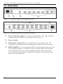
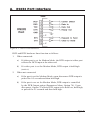
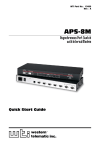
2.2. Back Panel
Figure 2.3: Instrument Back Panel (Model APS-8M)
Figure 2.4: Instrument Back Panel (Model APS-16M)
Power Cable Receptacle: AC powered units only. DC units include a
terminal block assembly as described in Section 4.1.2.
Power Switch
Modem Port (Line Port): For connection to your phone line. For
information regarding modem configuration, please refer to Section 6.
RS232 PORTS: For connection to RS232 console ports on user devices.
The APS-8M includes seven RS232 Ports, and the APS-16M includes
sixteen RS232 Ports. For more information, please refer to Section
4.3 (connection instructions), Appendix A (interface description), and
Section 5.2 (Setup Ports).
2-2
3. Getting Started
This Quick Start Guide describes a simplified installation procedure for the
APS-8M and APS-16M hardware, which will allow you to communicate with
the unit in order to demonstrate basic features and check for proper operation.
Note that this Quick Start Guide does not provide a detailed description of
unit configuration, or discuss advanced operating features in detail. In order
to take full advantage of the complete range of features provided by this unit,
it is strongly recommended that you review the Installation and Configuration
sections of this User's Guide after completing this Quick Start procedure.
3.1. Hardware Installation
3.1.1.
Apply Power to the APS-8/16M
Refer to the power rating nameplate on the APS-8/16M back panel, and then
connect the unit to an appropriate power source. Set the Master Power Switch
on the APS-8/16M back panel to the ON position.
3.1.2.
Connect your Telco Line to the APS-8/16M
Connect your phone line to the Line Port (Modem Port), located on the
APS-8/16M back panel. It is recommended to use a direct, dedicated POTS
line for connection to the Modem Port. Note that the APS-8M sees the Modem
Port as Port 8, and the APS-16M sees the Modem Port as Port 17.
3.1.3.
Connect a PC to the APS-8/16M
Use a standard null modem cable (provided with the unit) to connect your PC
COM port to the Port 1 connector on the APS-8/16M back panel.
3.2. Connect your Equipment to the Serial Ports
Use an appropriate DB9 cable to connect the RS232 Serial Port on your
equipment to the desired Serial Port on the APS-8/16M
• PCs and other DTE Devices: Use a standard null modem cable.
• External Modems and other DCE devices: Use a standard serial
modem cable.
3-1
APS-8M / APS-16M Asynchronous Port Switches; User’s Guide
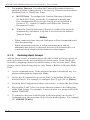
3.3. Communicating with the APS-8/16M
The APS-8/16M command mode allows you to check unit status, change
configuration parameters and connect and disconnect ports (including the
Modem Port.)
1.
Access Command Mode:
a)
Via Local PC: Start your communications program and then
press [Enter]. The "APS>" command prompt should appear.
c)
Via Modem: Use your communications program to dial the number
for the phone line which is connected to the internal modem. A
Password Prompt will be displayed. If you have not previously
defined the Supervisor Password, just press [Enter], without typing a
password. The "APS>" command prompt should be displayed.
Notes:
• If a password that permits access to Supervisor Mode has been
previously defined, a prompt will be displayed. Key in a Supervisor
Level password, and press [Enter]. If a Supervisor Level password
has not yet been defined, the prompt will not be displayed.
• When the APS-8/16M is shipped from the factory, communications
parameters are set as follows: 9600 bps, RTS/CTS Handshaking,
8 Data Bits, One Stop Bit, No Parity. Although these parameters
can be easily redefined, for this Quick Start procedure, it is
recommended to configure your communications program to accept
the default parameters.
2.
Review the Help Menu: At the "APS>" Command Prompt, type /H and
press [Enter] to display the Help Menu, which provides a basic listing of
all APS-8/16M commands.
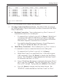
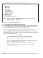
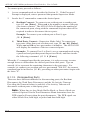
3.
Port Status Screen: Type /S and press [Enter] to display the Port Status
Screen (Figure 3.1), which summarizes conditions at all APS-8/16M
ports.
3-2
Getting Started
PORT STATUS: APS-M, Version 3.0, Site ID: (undefined)
PORT |
NAME
| CMD ACCESS | STATUS | MODE | BUFFER COUNT
-----+------------------+------------+--------+--------+-------------01 | (undefined)
| Unlocked | Free | Any
|
0
02 | (undefined)
| Unlocked | Free | Any
|
0
03 | (undefined)
| Unlocked | Free | Any
|
0
04 | (undefined)
| Unlocked | Free | Any
|
0
05 | (undefined)
| Unlocked | Free | Any
|
0
06 | (undefined)
| Unlocked | Free | Any
|
0
07 | (undefined)
| Unlocked | Free | Any
|
0
08 | Internal_Modem
| Unlocked | Free | Modem |
0
Enter /H for command menu.
APS>
Figure 3.1: The Port Status Screen (Model APS-8M Shown)
4.
Creating Connections Between Ports: The APS-8/16M can perform
two different types of port connections; Resident Connections and Third
Party Connections.
a)
b)
Resident Connection: Your resident port (e.g. Port 1) issues a /C
command to connect to a second port.
i.
To connect Port 1 to Port 2, type /C 2 [Enter]. While Port 1
is connected, the APS-8/16M will not recognize commands
issued at Port 1. However, the unit will recognize a Resident
Disconnect Sequence issued at Port 1 or Port 2.
ii.
Issue the Resident Disconnect Sequence (Logoff Sequence);
type ^X (press [Ctrl] and [X] at the same time).
Third Party Connection: Your resident port (e.g. Port 1) issues a
/C command to create a connection between two other ports.
i.
To connect Port 2 to Port 3, type /C 2 3 [Enter].
ii.
While Ports 2 and 3 are connected, Port 1 will still recognize
APS commands. Type /S [Enter] to display the Port Status
Screen. The "STATUS" column should now list Ports 2 and 3
as connected, and Port 1 as "Free".
iii. Issue a Third Party Disconnect command to disconnect Ports 2
and 3; type /D 2 [Enter]. The unit will display the "Are you
Sure (y/n)?" prompt. Type y and press [Enter] to disconnect.
iv.
Type /S [Enter] to display the Port Status Screen. The
"STATUS" column should now list Ports 2 and 3 as "Free".
3-3
APS-8M / APS-16M Asynchronous Port Switches; User’s Guide
5.
Exit Command Mode: At the "APS>" command prompt, type /X and
press [Enter]. The APS-8/16M will exit command mode.
This completes the Quick Start Guide for the APS-8/16M. Prior to placing the
unit into operation, please proceed to Sections 4 and 5 for complete installation
and configuration procedures.
3-4
4. Hardware Installation
4.1. Connecting Power to the APS Unit
The APS-8/16M is available in both AC and DC powered versions. When
connecting power, proceed as follows:
CAUTION:
• Before attempting to install this unit, please review the warnings
and cautions listed at the front of the user's guide.
• This device should only be operated with the type of power
source indicated on the instrument nameplate. If you are not
sure of the type of power service available, please contact your
local power company.
4.1.1.
AC Powered Units
Plug the power cable (supplied with the unit) into the receptacle on the back
panel, and then connect the power cable to an appropriate, grounded outlet.
The APS features a self adjusting power supply that automatically adapts to
power supplies between 100 and 240 VAC. Press the Power Switch ON. The
ON LED should light and the RDY LED should begin to flash.
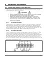
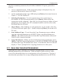
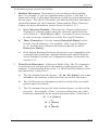
4.1.2.
DC Powered Units
The DC terminal block features two bus inputs as shown in Figure 4.1. This
allows the user to connect only one DC power source, or connect two DC
power sources where the second source serves as a backup. When connecting
the APS-8/16M to your DC power source, first remove the protective cover
from the terminal block, attach the wires from the -48V DC power source to
the screw terminals, connect your ground line to the labeled ground screw, and
then replace the protective cover.
Figure 4.1: Terminal Block Assembly (DC Units Only)
4-1
APS-8M / APS-16M Asynchronous Port Switches; User’s Guide
4.2. Connect a Telco Line to the Modem Port
Use a standard RJ-11 cable to connect your Telco outlet to the Modem (Line)
Port, located on the APS-8/16M back panel. Note that the APS-8M sees
the internal modem as Port 8, and the APS-16M sees the internal modem as
Port 17.
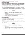
4.3. Connecting Devices to the APS Serial Ports
The serial RS232 Ports are standard DB9 connectors, configured as DTE Ports,
and are similar to a standard serial port on a PC. The APS-8M includes seven
serial RS232 ports, and the APS-16M includes sixteen serial RS232 ports. For
a detailed description of the RS232 Port interface, please refer to Appendix A.
1.
Access the APS-8/16M command mode.
2.
Determine which RS232 port will be used for connection to the new
device (e.g. Port 3).
3.
Use an appropriate DB9 cable to connect the RS232 serial port on the
device to the selected DB9 port on the APS-8/16M.
5.
4-2
a)
External Modems and other DCE Devices: Use a standard serial
modem cable.
b)
PCs and other DTE Devices: Use a standard null modem cable.
Select communication parameters for the port as described in Section 5.
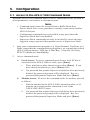
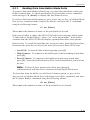
5. Configuration
5.1. Access to the APS-8/16M Command Mode
When the APS-8/16M command mode is active, commands can be invoked to
select parameters, and connect or disconnect ports.
Note:
• Command mode cannot be accessed from a Buffer Mode Port,
Passive Mode Port, or any port that is currently connected to another
APS-8/16M port.
• Configuration commands are not available at any port where the
Supervisor Mode has been disabled.
• Supervisor Mode commands can only be invoked by users who have
logged in using a password that permits access to Supervisor Mode.
1.
Start your communications program (e.g. HyperTerminal, TeraTerm, etc.).
Make certain that the communications program is set to match the default
APS-8/16M parameters: 9600 bps, 8-Data Bits, 1-Stop Bit, No Parity,
RTS/CTS (hardware) handshaking.
2.
Access command mode.
a)
b)
Local Access: To access command mode from a local PC that is
connected to the APS-8/16M via cable, press [Enter].
i.
There must be no other characters preceding [Enter]. If you
have already hit other keys, press [Enter] twice.
ii.
If a password that permits Supervisor Mode has been previously
defined, the password prompt will be displayed. Key in a
password that permits Supervisor Mode and press [Enter].
Modem Access: To access the command mode via modem, proceed
as follows:
i.
Dial the number for the APS-8/16M’s internal modem, or (if
present) an external modem connected to one of the
APS-8/16M’s RS232 ports.
ii.
If a password that permits Supervisor Mode has been previously
defined, the password prompt will be displayed. Key in a
password that permits Supervisor Mode and press [Enter].
5-1
APS-8M / APS-16M Asynchronous Port Switches; User’s Guide
5.2. System SetUp Ports
Ports 1 and 2 are designated as System SetUp Ports, and will therefore, always
permit password protected access to Supervisor Mode.
In order to ensure that access to command functions is always available, Ports
1 and 2 cannot be configured as Buffer Mode or Passive Mode Ports (Buffer
Mode Ports and Passive Mode Ports are not able to access command mode.) In
addition, Ports 1 and 2 always permit password protected access to Supervisor
Mode; the Supervisor Mode cannot be disabled at either of these two ports.
5.3. Password Functions
The APS-8/16M’s password directory allows you to define up to 32 different
passwords. These passwords are not only used to protect access to the
APS-8/16M unit, but are also used to determine the type of commands that
each user will be allowed to invoke, and the ports that each user will be
allowed to connect. This is accomplished by either granting or denying each
password’s access to Supervisor Mode and specifying permitted ports via the
Password Directory.
Passwords that have been granted access to Supervisor Mode are allowed to
change configuration parameters and may connect to any APS-8/16M port. On
the other hand, passwords which are denied access to Supervisor Mode are
not allowed to change configuration parameters, and are restricted to the ports
specifically allowed by that password. Therefore, the password entered during
login determines whether or not you will be able to invoke Supervisor Mode
commands, and also determines which ports you will be allowed to connect
to. Note that the password directory feature is described in greater detail in
Section 5.4.1.
Note that once you have defined at least one password that permits access to
Supervisor Mode, the APS-8/16M will display a password prompt whenever
you attempt to access command mode. If a valid password, which allows
access to Supervisor Mode is entered, the APS-8/16M will then start up
in Supervisor Mode. Supervisor Level commands are summarized in
Section 11.3 of this User’s Guide.
5-2
Configuration
Notes:
• If you do not define at least one password that permits access
to Supervisor Mode, then Supervisor Level commands will be
available to all ports, and port access and configuration functions
will not be password protected.
• If you wish to restrict users from changing APS-8/16M
configuration parameters or connecting to restricted ports, you must
define at least one password that permits access to Supervisor Mode
as described in Section 5.4.1.
• If the unit is reset to default parameters, all passwords will be
erased, and Supervisor Level commands will be available at all
ports, without password protection.
Normally, passwords that permit access to Supervisor Mode can be entered at
any port in order to gain access to Supervisor command functions. Note that
if you wish to completely deny a port’s access to Supervisor Mode (even with
a Supervisor Password), the Port Parameters menus (/P) can be used to disable
the Supervisor Mode at any RS232 Port except for ports 1 and 2 (the System
SetUp Ports.) The Supervisor Mode cannot be disabled at System SetUp
Ports 1 and 2.
5.4. The System Parameters Menu
Before configuring individual ports, the System Parameters should be defined.
The System Parameters Menu (/F) allows you to set the Site ID Message,
enable/disable the Password on Dial Back Function, set the number of Dial
Back Attempts, set the Dial Back Delay Value, and access the menus which are
used to define passwords and access rights. All parameters that are defined via
the System Parameters Menu are global, and will be applied to all
APS-8/16M ports.
Notes:
• The Site ID message cannot include double quotes.
• Both the Site ID and Password Directory will be cleared if the
APS-8/16M is initialized to default settings.
• The System Parameters Menu is only available in Supervisor Mode.
5-3
APS-8M / APS-16M Asynchronous Port Switches; User’s Guide
SYSTEM PARAMETERS:
1.
2.
3.
4.
5.
Site-ID:
Password on Dial Back:
Dial Back Attempts:
Dial Back Delay:
Edit Password Directory
(undefined)
Off
3
30 Secs
Enter: #<CR> to change,
<ESC> exit ...
Figure 5.1: The System Parameters Menu (/F)
To define System Parameters, you must first access command mode, and then
type /F [Enter] to display the System Parameters Menu (Figure 5.1.) The
System Parameters Menu allows you to define the following:
1.
Site ID: Type 1 and press [Enter], a prompt will appear. Key in the
desired text and press [Enter]. The Site ID will be listed on the status and
diagnostic screens. (Up to 32 chars.; Default = undefined.)
2.
Password on Dial Back: Enables/Disables the "Password on Dial Back"
feature as described in Section 5.4.2. (Default = Off.)
3.
Dial Back Attempts: Sets the number of times that the APS-8/16M
will attempt to call the dial back number when the Dial Back feature is
properly configured and enabled. For more information on the Dial Back
feature, please refer to Section 5.4.2. (Default = 3.)
4.
Dial Back Delay: Sets the amount of time that will elapse between Dial
Back Attempts. For more information on the Dial Back Feature, please
refer to Section 5.4.2. (Default = 30 Seconds.)
5.
Edit Password Directory: Provides access to a series of menus that are
used to create, edit, and delete APS-8/16M passwords as described in
Section 5.4.1.
5-4
Configuration
EDIT PASSWORD DIRECTORY:
1.
2.
3.
4.
Add Name/Password
Edit/Delete from List
Edit/Delete from Search
Delete Entire Directory
Enter: #<CR> to select,
<ESC> for previous menu ...
Figure 5.2: The Edit Password Directory Menu
5.4.1.
The Password Directory
APS-8/16M passwords are defined using the "Edit Password Directory"
menu, which is accessed via the System Parameters menu (/F). In addition
to assigning command level privileges to each password, the Edit Password
Directory function also allows you to determine which ports each password
will be allowed to access, and includes prompts that are used to configure
several Dial Back parameters. The Password Directory allows for the
definition of up to 32 separate passwords.
Note:
• The Edit Password Directory menu is only available to users who
have logged into command mode using a password that permits
access to Supervisor Mode.
• The /V command can also be issued to view the Password Directory.
To activate the Edit Password Directory menu, you must first access the
command mode, and then type /F and press [Enter] to display the System
Parameters Menu. At the System Parameters Menu, type 5 and press [Enter]
to display the Edit Password Directory menu (Figure 5.2.) The Edit Password
Directory Menu offers the following options:
1.
Add Name/Password: Creates new passwords and assigns Supervisor
Mode access and port access rights as described in Section 5.4.1.1.
2.
Edit/Delete from List: Edits/Deletes passwords. The desired password
is selected by scrolling through a list of all passwords as described in
Section 5.4.1.2.
3.
Edit/Delete from Search: Edits/Deletes passwords. The desired
password is selected using a search function as described in
Section 5.4.1.2.
4.
Delete Entire Directory: Clears the password directory, and deletes all
existing passwords as described in Section 5.4.1.3.
5-5
APS-8M / APS-16M Asynchronous Port Switches; User’s Guide
ADD NAME/PASSWORD:
1.
2.
3.
4.
5.
6.
7.
Name:
Password:
Dial Back #:
Dial Back Mode:
Supervisor Mode:
Port Access:
Save Entry
(undefined)
(undefined)
(undefined)
Off
Off
None
Enter: #<CR> to select,
<ESC> for previous menu ...
Figure 5.3: The Add Name/Password Menu (Defaults Shown)
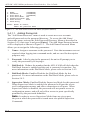
5.4.1.1. Adding Passwords
The "Add Name/Password" menu is used to create new user accounts
and add passwords to the password directory. To access the Add Name/
Passwords menu, activate the Edit Password Directory Menu as described in
Section 5.4.2, then type 1 and press [Enter]. The Add Name/Password menu
will be displayed as shown in Figure 5.3. The Add Name/Password Menu
allows you to assign the following parameters:
1.
Name: Assigns a username to the password. Note that usernames are not
required when logging into command mode, and are used for descriptive
purposes only.
2.
Password: After keying in the password, the unit will prompt you to
verify the password by re-keying it.
3.
Dial Back #: Defines the number that the APS-8/16M will dial when the
Dial Back feature is enabled and the unit is contacted via modem. For
more information on the Dial Back Mode, please refer to Section 5.4.2.
4.
Dial Back Mode: Enables/Disables the Dial Back Mode for this
password. For more information on the Dial Back Mode, please refer to
Section 5.4.2.
5.
Supervisor Mode: Enables/Disables Supervisor Mode for this password.
When Supervisor Mode is enabled, the password will provide access
to all configuration menus, and allow connections to all ports. When
Supervisor Mode is disabled, the password will not permit access to
configuration menus, and will only allow access to ports specifically
permitted by the password definition.
Note: In order to access Supervisor Mode from any given port,
the port at which the password is issued must also permit Supervisor
Commands.
5-6
Configuration
EDIT/DELETE NAME/PASSWORD:
1.
2.
3.
4.
5.
6.
7.
8.
Name:
Password:
Dial Back #:
Dial Back Mode:
Supervisor Mode:
Port Access:
Save Entry
Delete Entry
test
(defined)
5556789
On
On
1, 2, 3, 4, 5, 6, 7, 8
Type: “<”<Enter> previous entry, “>”<Enter> next entry,
<number><Enter> to selection,
<ESC> to abort ...
Figure 5.4: The Edit/Delete Name/Password Menu (Sample Values Shown)
6.
Port Access: The ports that this password will be allowed to create
connections with. Note that several passwords can provide access to
the same port. To select ports, type 6, press [Enter] and follow the
instructions in the resulting submenu.
7.
Save Entry: Note that if you exit from the menu without first saving, the
password will not be saved.
5.4.1.2. Editing and Deleting Passwords:
The Edit Password Directory Menu (Figure 5.2) provides two different
methods for selecting the password you wish to edit or delete; passwords
can either be selected by scrolling through the password list, or by using a
search routine. To edit or delete existing passwords, access the Edit Password
Directory menu and proceed as follows:
1.
Select the account that you wish to edit or delete:
a)
From List: To find the desired password from a list of all
passwords, type 2, press [Enter], then follow the instructions in the
resulting submenu.
b)
From Search: To search for a specific password, type 3, press
[Enter], then follow the instructions in the resulting submenu.
2.
Edit Password: After finding the desired password, the "Edit/Delete
Name/Password" Menu (Figure 5.4) will be displayed. Items 1 through 6
are used to select and change parameters, and function identically to the
corresponding items in the Add Name/Password menu. Item 7 is used to
save the edited password and parameters. Note that if you exit from the
menu without first saving, newly selected parameters will be discarded.
3.
Delete Password: After finding the desired password, the "Edit/Delete
Name/Password" Menu will be displayed. To delete the password, type 8
and press [Enter].
5-7
APS-8M / APS-16M Asynchronous Port Switches; User’s Guide
5.4.1.3. Deleting the Entire Password Directory
The Edit Password Directory menu (Figure 5.2) also allows you to delete the
entire password directory, rather than accessing each individual password
and deleting them one at a time. To delete the Password Directory and clear
all passwords, activate the "Edit Password Directory" Menu as describe in
Section 5.4.1, type 4 and press [Enter]. The unit will then display a "Sure?"
prompt and wait for confirmation before proceeding.
Notes:
• Deleted passwords cannot be recovered.
• If the Password Directory is deleted, the password prompt will no
longer be displayed, and users will be able to access Supervisor
Mode without a password. In order to restrict access to Supervisor
commands, you must define at least one password that permits
access to Supervisor Mode.
5.4.2.
The Dial Back Function
The Dial Back Function provides an additional layer of security when callers
attempt to access command mode via modem. When this function is properly
configured, callers will not be granted immediate access to command mode
upon entering a valid password; instead, the unit will disconnect, and dial a
user-defined number before allowing access via that number. If desired, users
may also be required to re-enter the password after the APS-8/16M dials back.
Note that a separate Dial Back Number can be defined for each password, and
the feature may also be independently enabled for each password. To enable
this function, proceed as follows:
1.
Access command mode using a port and password that permit Supervisor
Mode. At the command prompt, type /F and press [Enter] to display the
System Parameters menu.
2.
System Parameters Menu: Note that dial back parameters selected
via this menu are global, and will apply to all passwords. Define the
following parameters:
• Item 2, Password on Dial Back: (Optional) Determines whether or
not the Dial Back Mode will require the answering party to re-enter
their password after a Dial Back is performed.
• Item 3, Dial Back Attempts: The number of times the APS-8/16M
will attempt to call the dial back number.
• Item 4, Dial Back Delay: The amount of time the APS-8/16M will
wait between Dial Back attempts.
5-8
Configuration
3.
Edit Password Directory: From the System Parameters Menu, type
5 and press [Enter] to display the Edit Password Directory Menu. At
this point, you may either define new passwords that use the Dial Back
Function, or alter existing passwords to include the Dial Back Function.
The following parameters should be defined in the Add Name/Password
Menu or Edit/Delete Password/Name Menu:
• Item 3, Dial Back #: The number that will be called when a Dial Back
is performed. This is the number for the password owner’s modem.
• Item 4, Dial Back Mode: Enables/Disables the Dial Back function for
this password. When enabled, this password will require a dial back to
be performed whenever this password user attempts to access the unit
via modem.
Note: In order for new parameters to be applied, you must save each
password before leaving the menu.
Dial Back Example:
Assume that the unit is configured as follows:
System Parameters Menu:
• Item 2, Password on Dial Back: On
• Item 3, Dial Back Attempts: 3
• Item 4, Dial Back Delay: 30 Seconds
Add Name/Password Menu:
• Item 1, Name: Test
• Item 2, Password: test
• Item 3, Dial Back #: 5551234
• Item 4, Dial Back Mode: On
Given this configuration, the unit would behave as follows :
1.
Password "test" Entered at Modem Port: Unit confirms that password
is valid, then disconnects.
2.
Dial Back: Unit dials "555-1234" (the Dial Back Number for "test") and
waits for the user’s remote modem to answer.
3.
Password on Dialback: When the modem at the Dial Back Number
answers, the APS-8/16M will prompt the user to enter the password
before allowing access to command mode.
4.
Dial Back Attempts and Delays: If the modem does not answer, the unit
will then attempt to redial the number three times (Dial Back Attempts),
and will pause for approximately 30 seconds (Dial Back Delay) between
each redial.
5-9
APS-8M / APS-16M Asynchronous Port Switches; User’s Guide
5.5. Port Configuration
5.5.1.
Configuration Conventions
When responding to prompts, invoking commands, and selecting items from
port configuration menus, note the following:
• To select an item from a Port Configuration menu, key in the number for
the item and press [Enter].
• To clear an item in a Port Configuration menu, enter the number for the
desired item and press [Enter]. When the prompt appears, press [Space]
and then press [Enter].
• When defining the Port Name, do not use the forward slash character (/),
double quotes ("), the asterisk character (*), or blank spaces.
• Port Names cannot begin with a number.
• Refer to the instructions in each screen for additional functions available
under that screen.
• To exit a menu or prompt without changing its current value, press [Esc].
• Passwords are case sensitive. When defining passwords, note the exact
text, including the case of each character.
• If you are configuring the APS-8/16M unit via modem, communication
parameters will not be changed until after you exit from command mode
and disconnect from the APS-8/16M unit.
5-10
Configuration
5.5.2.
Port Modes
The APS-8/16M offers four different port operation modes; Any-to-Any Mode,
Passive Mode, Buffer Mode, and Modem Mode. The Port Modes function as
follows:
• Any-to-Any Mode: Allows communication between connected ports.
Any-to-Any Mode Ports can be connected to other Any-to-Any, Passive,
Buffer, or Modem Mode Ports by accessing command mode and invoking
the /C command (see Section 8.1.1). The Any-to-Any Mode is available
to all APS-8/16M ports, except the Internal Modem Port (The Internal
Modem Port is Port 8 on the APS-8M, and Port 17 on the APS-16M.)
• Passive Mode: Allows communication between connected ports, but
does not allow access to command mode. Passive Mode Ports can be
connected by accessing command mode from a free Any-to-Any or
Modem Mode port and invoking the /C command (see Section 8.1.1).
The Passive Mode is not available to Ports 1 and 2, or the Internal Modem
Port (The Internal Modem Port is Port 8 on the APS-8M, and Port 17 on
the APS-16M.)
• Buffer Mode: Allows collection and storage of data received from
connected devices. Collected data can be retrieved by accessing
command mode from a free Any-to-Any or Modem Mode Port, and
issuing the Connect Command (/C.) Note that the Buffer Mode also
allows pass-through communication with the connected device. The
Buffer Mode is not available to Ports 1 and 2, or the Internal Modem Port
(The Internal Modem Port is Port 8 on the APS-8M, and Port 17 on the
APS-16M.)
• Modem Mode: A Modem Mode port can perform all functions normally
available in Any-to-Any Mode, but the Modem Mode also allows
definition of a Hang-Up String, Reset String, and Initialization String.
Any APS-8/16M RS232 port can be configured for Modem Mode, and the
Internal Modem port is always configured for Modem Mode.
For more information on Port Modes, please refer to Section 8.
5-11
APS-8M / APS-16M Asynchronous Port Switches; User’s Guide
PORT PARAMETERS #01:
1.
2.
3.
4.
5.
6.
7.
8.
9.
10.
11.
12.
13.
14.
Port Name:
Baud Rate:
Bits/Parity:
Stop Bits:
Handshake Mode:
Port Mode:
64. DTR Output:
Supervisor Mode:
Logoff Character:
Sequence Disconnect:
Timeout Disconnect:
Response Type:
Command Echo:
Accept Break:
Invalid Access Lockout:
(undefined)
9600
8-None
1
RTS/CTS
Any-to-Any
Pulse
Permit
^X
One Character Only
Off
Verbose
On
Yes
Off
Enter: “<” previous port,
“>” next port,
<ESC> exit ...
Figure 5.5: Port Configuration Menu (Port 1 Shown)
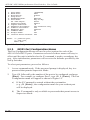
5.5.3.
RS232 Port Configuration Menus
The Port Configuration Menus are used to select options for each of the
APS-8/16M’s RS232 ports. Parameters selected via these menus will stay in
effect until the unit is initialized or the /P command is used to reconfigure the
port. After initialization, parameters will revert to the defaults specified by the
SetUp Switches.
To select port parameters, proceed as follows:
1.
Access command mode. If the password prompt is displayed, key in a
password that permits Supervisor Mode.
2.
Type /P, followed by the number of the port to be configured, and press
[Enter]. For example, to configure Port 1, type /P 1 [Enter]. The Port
Configuration menu will appear as shown in Figure 5.5.
5-12
a)
If the /P Command is entered without the port number
(e.g. /P [Enter]), the configuration menu for your resident port
will be displayed.
b)
The /P command is only available to passwords that permit access to
Supervisor Mode.
Configuration
The Port Configuration menu offers the following options:
1.
Port Name: (Up to 16 characters) Assigns a name to the port.
• (APS-8M Defaults: Ports 1 through 7 = undefined;
Port 8 = "Internal_Modem").
• (APS-16M Defaults: Ports 1 through 16 = undefined;
Port 17 = "Internal_Modem").
2.
Baud Rate: Selects the baud rate for the port. Can be set to any standard
rate from 300 bps to 115.2K bps. (Default = 9600 bps)
3.
Bits/Parity: (Default = 8-None).
4.
Stop Bits: (Default = 1).
5.
Handshake Mode: Selects the handshake format for this port; XON/
XOFF, RTS/CTS (hardware), Both, or None. (Default = RTS/CTS).
6.
Port Mode: Defines the operation mode for this port. (Default: Ports 1
through 7 = Any-to-Any Mode; Port 8 = Modem Mode).
Notes:
• Ports 1 and 2 cannot be configured as Passive Mode or Buffer Mode
ports.
• The Internal Modem Port is always configured for Modem Mode,
and cannot be set to Any-to-Any, Buffer, or Passive Mode.
When Any-to-Any, Passive, or Buffer Mode is selected, the unit will
display the DTR Output prompt (item 64) as shown in Figure 5.5. The
DTR Output prompt is not displayed when Modem Mode is selected.
64. DTR Output: Determines how DTR will react when this port
disconnects. DTR can be held low, held high, or pulsed for 0.5
seconds and then held high. In the default state, DTR will pulse
for 0.5 seconds and then remain high. For more information on
hardware lines, please refer to Appendix A. (Default = Pulse).
5-13
APS-8M / APS-16M Asynchronous Port Switches; User’s Guide
PORT PARAMETERS #03:
1.
2.
3.
4.
5.
6.
7.
8.
9.
10.
11.
12.
13.
14.
Port Name:
Baud Rate:
Bits/Parity:
Stop Bits:
Handshake Mode:
Port Mode:
61. Reset String:
62. Init String:
63. Hang-Up String:
Supervisor Mode:
Logoff Character:
Sequence Disconnect:
Timeout Disconnect:
Response Type:
Command Echo:
Accept Break:
Invalid Access Lockout:
(undefined)
9600
8-None
1
RTS/CTS
Modem
ATZ
AT&C1&D2S0=1
(undefined)
Permit
^X
One Character Only
15 Min
Verbose
On
Yes
Off
Enter: “<” previous port,
“>” next port,
<ESC> exit ...
Figure 5.6: Port Parameters Menu; Modem Mode (Port 3 Shown)
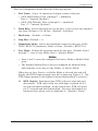
When the Port Mode is set to Modem Mode, the menu will include
additional prompts (see Figure 5.6), which are used to define the
following:
61. Reset String: If necessary, this prompt can re-define the modem
reset string, which is sent prior to the Initialization string. (Up to 48
Chars., Default = ATZ).
62. Initialization String: Defines a command string that can be sent to
initialize a modem to settings required by your application. (Up to
48 Characters, Defaults: Port 1 through 7 = AT&C1$D2S0=1;
Port 8 =ATM0&C1$D2S0=1).
63. Hang-Up String: Although the APS-8/16M will pulse the DTR line
to hang-up an attached modem, the Hang-Up string is often useful
for controlling modems that do not use the DTR line. (Up to 48
Characters, Default = undefined).
Notes:
• When communicating with the APS-8/16M via modem,
communication parameters will not be changed until you exit from
command mode and discontinue the modem connection to the unit.
• For a list of basic AT commands for the Internal Modem, please
refer to Section 6. For a complete listing of all available AT
commands and S-Registers, please refer to the "MT5634 Modem AT
Command Set" document in our User’s Guide Archive at the WTI
web site: http://www.wti.com/guides/guidarch.htm.
5-14
Configuration
7.
Supervisor Mode: Permits or denies access to Supervisor Mode at this
port. When enabled (Permit), and a password that permits Supervisor
Mode is entered, the port will allow access to Supervisor Mode
commands. When disabled (Deny), the port will not enter Supervisor
Mode, even when a password that normally permits access to Supervisor
Mode is entered. (Default = Permit).
Note: The Supervisor Mode cannot be disabled at Ports 1 or 2.
8.
Logoff Character: Defines the Logoff Character for this port. The
Logoff Character determines the command(s) or character(s) that must
be issued at this port in order to disconnect from a second port (Resident
Disconnect). (Default = ^X ([Ctrl] plus [X])).
Note: When redefining the Logoff Character, make certain to select a
character that does not normally occur in your data.
9.
Sequence Disconnect: Enables/Disables and configures the Resident
Disconnect command. This prompt offers the option to either disable the
Sequence Disconnect, or select a one character format or a three character
format. (Default = One Character). Note the following:
• When a Resident Connection is initiated, the APS-8/16M will send a
message which lists the connected ports, and displays the one character
or three character command that will be required in order to disconnect.
• The One Character Disconnect sequence is intended for situations
where the destination port will not receive the disconnect command.
When the Three Character format is selected, the disconnect sequence
will pass through to the destination port prior to breaking the
connection.
• When the One Character format is selected, resident connections are
terminated by entering the selected Logoff Character only. There is no
need to press [Enter] before and after the Logoff Character when the
One Character format is selected.
• When the Three Character format is selected, the Resident Disconnect
Sequence will use the format "[Enter]LLL[Enter]", where L is the
selected Logoff Character.
5-15
APS-8M / APS-16M Asynchronous Port Switches; User’s Guide
10. Timeout Disconnect: Enables and selects the Timeout Period for this
port. If enabled, and the port does not receive or transmit data for the
specified Timeout Period, the port will disconnect. In Any-to-Any Mode,
Passive Mode, or Buffer Mode, the default setting for this item is "OFF".
When the port is set for Modem Mode, the default setting for this item is
15 minutes.
Notes:
• The Timeout Disconnect is also applied to non-connected ports that
are left in command mode. If no additional data activity is detected,
an unconnected port will exit from command mode when the
Timeout Disconnect value expires.
• When connected ports time out and are disconnected, both ports will
also exit from command mode.
11. Response Type: Selects the type of messages that this port will send in
response to commands. The user can select Verbose (English Text), Terse
(Numeric / Abbreviation), or Quiet Mode (No Response).
(Default = Verbose).
12. Command Echo: Enables or Disables the command echo for this port.
(Default = On).
13. Accept Break: Determines whether the port will accept breaks received
from the attached device, and pass them along to a connected port. When
enabled, breaks received at this port will be passed to any port that this
port is connected to, and sent along to the device connected to the other
port. When disabled, breaks will be refused at this port, and hence, not
sent to the other port. (Default = Yes)
14. Invalid Access Lockout: Enables/Disables the Invalid Access Lockout
feature as described in Section 5.5.4. Briefly, the Invalid Access Lockout
feature can be used to automatically disable a port when a user-defined
number of invalid access attempts are detected. (Default = Off.)
5-16
Configuration
5.5.4.
The Invalid Access Lockout Feature
When properly configured and enabled, the Invalid Access Lockout feature
will watch all login attempts made at a given port. If the port exceeds the
selected number of invalid attempts, then that port will be automatically
disabled for a user-defined length of time.
Note that when an Invalid Access Lockout occurs, you can either wait for the
Lockout Duration period to elapse, or issue the /UL command to instantly
unlock all ports.
Note: The Invalid Access Lockout feature can be individually
enabled/disabled at each port.
The Invalid Access Lockout Feature is configured and enabled using the
Port Parameters Menu for the desired port. When "Invalid Access Lockout"
is selected, the APS-8/16M will display a submenu which allows you to
configure the following parameters:
1.
Lockout Access: Enables/Disables Invalid Access Lockout at this port.
2.
Lockout Attempts: The number of invalid access attempts required to
trigger the Invalid Access Lockout feature.
3.
Lockout Duration: The length of time that ports will remained locked
when an Invalid Access Lockout occurs. Note that if the duration is set to
"0", the port will remained locked until the /UL command is issued.
5-17
APS-8M / APS-16M Asynchronous Port Switches; User’s Guide
COPY PORT PARAMETERS:
1.
2.
3.
4.
5.
6.
7.
8.
9.
10.
11.
12.
13.
14.
Port Name:
Baud Rate:
Bits/Parity:
Stop Bits:
Handshake Mode:
Port Mode:
64. DTR Output:
Supervisor Mode:
Logoff Character:
Sequence Disconnect:
Timeout Disconnect:
Response Type:
Command Echo:
Accept Break:
Invalid Access Lockout:
(Note: ports 1 & 2 will NOT have restricted values changed.)
Enter: parameter # <CR> to define parameter value to copy to all ports,
-<CR> to remove all values set,
X<CR> to exit WITHOUT copy,
<ESC> to copy to ports and exit ...
Figure 5.7: The Copy Port Parameters Menu
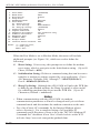
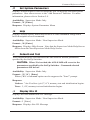
5.6. Copying Parameters to All Ports
The /CP command (Copy Port Parameters) provides a convenient means for
selecting similar parameters for all APS-8/16M RS232 ports.
When the /CP command is invoked, the unit will display a menu which allows
you to select port communication parameters, then copy them to all
APS-8/16M RS232 ports. The Copy Port Parameters menu can be used to set
all parameters for all RS-232 Ports, or define only a select group of parameters
and then copy them to all ports.
Notes:
• The /CP command is only available in Supervisor Mode.
• The /CP command cannot be used to set Ports 1 and 2 to Passive
Mode or Buffer Mode (Port Mode, Item 6.)
• The /CP command cannot be used to disable the Supervisor Mode at
Ports 1 and 2 (Supervisor Mode, Item 7.)
• The /CP command cannot be used to change the Port Mode for
the Internal Modem Port. The Internal Modem Port is always
configured for Modem Mode.
5-18
Configuration
To select common parameters for all APS-8/16M RS-232 ports, proceed as
follows:
1.
Access command mode. If the password prompt is displayed, key in a
password that permits Supervisor Mode.
2.
At the command prompt, type /CP and press [Enter], the menu shown in
Figure 5.7 will be displayed.
3.
Selecting Parameters: To select parameters to be copied, key in
the number for the desired parameter, press [Enter], then follow the
instructions in the submenu. Note that it is not necessary to define all port
parameters, for example, the /CP command could be used to select only
the Baud Rate for all ports.
4.
Clear Menu: After defining several parameters, if you wish to clear the
/CP menu and start again, type - (dash) and press [Enter], the menu will
be reset.
5.
Exit Without Copy: To exit from the Copy Parameters menu without
copying selected parameters to all RS232 ports, type X and then press
[Enter]. The APS-8/16M will exit from the Copy Parameters menu and
return to the command prompt.
6.
Copy Parameters: When you have finished selecting parameters, press
[Esc] to copy the selected parameters to all APS-8/16M RS-232 Ports and
exit from the Copy Port Parameters menu. Note that the APS-8/16M will
display a "Sure" prompt before copying parameters to other ports.
5.7. Save User Selected Parameters
Although this step is optional, it is strongly recommended to save all userdefined parameters to an ASCII file. This will allow quick recovery in the
event of accidental deletion or reconfiguration of port parameters. Section 9
describes the procedure for saving configuration parameters to an ASCII file.
5-19
APS-8M / APS-16M Asynchronous Port Switches; User’s Guide
5-20
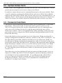
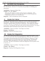
6. The Internal Modem
This section lists commonly used AT commands for the APS-8/16M’s internal
modem, and briefly describes the procedure for communicating with the
internal modem. Please note that although APS-8/16M includes an internal
modem, any APS-8/16M RS232 port can also be configured for connection to
an external modem.
6.1. Communicating with the Internal Modem
To communicate with the APS-8/16M’s internal modem, proceed as follows:
1.
Access the APS-8/16M command mode as described in Section 5.1.
Notes:
• If you log on to the APS-8/16M using a password that does not
permit Supervisor Mode, then you will only be able to connect to
the Internal Modem Port if your password allows access to that port.
Passwords that permit Supervisor Mode will always allow access to
all ports.
• To access the internal modem’s command mode from a remote
location, you must first dial into an external modem installed at one
of the other RS232 ports, and then proceed as described below. The
internal modem’s command mode cannot be accessed via a remote
connection to the internal modem.
2.
When the APS> command prompt appears, type /C 8 and press [Enter]
to connect to the Internal Modem Port (Port 8 on the APS-8M, or Port 17
on the APS-16M).
3.
When the connection is established, the APS-8/16M will respond with a
connect message that lists the port number or name and currently selected
disconnect command.
6-1
APS-8M / APS-16M Asynchronous Port Switches; User’s Guide
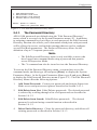
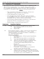
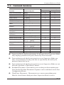
6.2. Common AT Commands
This section lists some of the most commonly used AT commands for the
APS-8/16M’s internal modem. For a complete listing of all available
AT Commands and S-Registers, please refer to the "MT5634 Modem AT
Command Set" document at http://www.wti.com/guides/guidarch.htm.
Notes:
• Type commands in either upper or lower case. Do not use a
combination of upper and lower case characters.
• Use the Backspace key to delete errors.
• All commands begin with the AT prefix, and are invoked by
pressing [Enter]. The only exceptions are A/ (Repeat Previous
Command) and +++ (Exit to on-line command mode).
• The maximum command length is 40 characters. This does not
include the AT Prefix, Carriage Returns, or spaces.
• Default settings are marked with an asterisk (*).
Command
Function/Options
Zn
Reset Modem. Resets modem parameters to default values.
Z0
Reset modem to profile saved by the last
&W command.
Z1
Same as Z0
Ds
6-2
Dials telephone number s. Where s may be up to 40 characters
long and may include the numbers 0-9, *, #, B, C, and D
characters and the L, P, T, V, W, S, comma (,), semicolon (;), !,
@, ^ and $ dial string modifiers.
Dial String Modifiers:
L
Redial last number. (Must be placed immediately
after ATD.)
P
Pulse-dial following numbers in command line.
T
Tone Dial following numbers in command line.
W
Wait for a new dial tone before continuing to dial
(X2, X4, X5, X6 or X7 must be selected.)
,
(Comma) Pause during dialing for time set in
Register S8.
;
Return to command mode after dialing.
(Place at end of dial string.)
!
Hook Flash. Causes modem to go on-hook for
one half second, then off hook again.
@
Wait for quiet answer. Causes modem to wait for a
ringback, then 5 seconds of silence, before processing
the next part of the command. If silence is not detected,
the modem returns a NO ANSWER code.
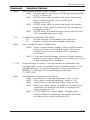
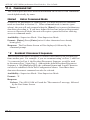
The Internal Modem
Command
Function/Options
Data Terminal Ready (DTR) Control.
&Dn
&D0 Modem ignores true status of DTR signal and responds
as if it is always on.
&D1 If DTR drops while in online data mode, the modem
enters command mode, issues an OK, and
remains connected.
* &D2 If DTR drops while in online data mode, the modem
hangs up. If the signal is not present, the modem will
not answer or dial.
&D3 If DTR drops, the modem hangs up and resets as if an
ATZ command had been issued.
En
&Wn
Set Modem Command Mode Echo.
E0
Disable echoing of command mode characters.
* E1
Enable echoing of command mode characters.
Store Current Modem Configuration.
&W0 Stores current modem settings in non-volatile memory
and causes them to be loaded instead of the factory
defaults at power-on or when the ATZ command
is invoked.
* &W1 Clears user default settings from non-volatile memory
and causes the factory defaults to be loaded at power-on
or following the ATZ command.
+++AT
In-band Escape Sequence. Puts the modem in command mode
(and optionally issues a command) while remaining online. Type
+++AT and up to six optional command characters; then press
[Enter]. Used mostly to issue the hangup command:
+++ATT<CR>.
&Qn
Asynchronous Communications Mode.
&Q0 Asynchronous with data buffering. Same as /N0.
* &Q5 Error control with data buffering. Same as /N3.
&Q6 Asynchronous with data buffering. Same as /N0.
&Q8 MNP error control mode. If MNP error control is not
established, the modem falls back according to the
setting in Register S36.
&Q9 V.42 or MNP error control mode. If neither error
control method is established, the modem falls back
according to the setting in Register S36.
6-3
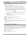
APS-8M / APS-16M Asynchronous Port Switches; User’s Guide
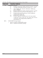
Command
Function/Options
Information Request
In
I0
Display default speed and controller firmware version.
I1
Calculate and display ROM checksum (e.g., 12AB.)
I2
Check ROM and verify the checksum, displaying
OK or ERROR
I3
Display default speed and controller firmware version.
I4
Display firmware version for data pump (e.g., 94.)
I5
Display the board ID: software version, hardware
version, and country ID.
I9
Display the country code.
I11
Display diagnostic information for the last modem
connection, such as link type, line speed, type of error
correction / data compression, number of
past retrains, etc.
&En
6-4
XON/XOFF Pacing Control.
* &E12 Disables XON/XOFF pacing.
&E13 Enables XON/XOFF pacing.
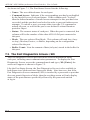
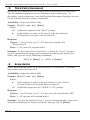
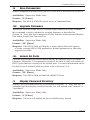
7. The Status Screens
The APS-8/16M Status Screens display the connection status and
communication parameters for the RS-232 ports. Basically, There are four
different status screens; The Port Status screen (/S), the Port Diagnostics screen
(/SD), the Port Parameters screens (/W), and the View Password Directory
screen.
7.1. The Port Status Screen (/S)
The Port Status Screen lists the general status of the RS-232 ports. To display
the Port Status Screen, access the command mode and type /S [Enter], the
screen will appear as shown in Figure 7.1.
Although the Port Status Screen can be displayed by passwords that permit
Supervisor Mode and passwords that do not permit Supervisor Mode, note
that the resulting screen will appear slightly different, depending upon the
Supervisor Mode access rights of the port and password that invoked the /S
command. When the /S command is invoked by a user who does not have
access to Supervisor Mode, the Port Status Screen will only display the status
of those ports that are specifically allowed for the password entered at log in.
PORT STATUS: APS-M, Version 3.0, Site ID: (undefined)
PORT |
NAME
| CMD ACCESS | STATUS | MODE | BUFFER COUNT
-----+------------------+------------+--------+--------+-------------01 | (undefined)
| Unlocked | Free | Any
|
0
02 | (undefined)
| Unlocked | Free | Any
|
0
03 | (undefined)
| Unlocked | Free | Any
|
0
04 | (undefined)
| Unlocked | Free | Any
|
0
05 | (undefined)
| Unlocked | Free | Any
|
0
06 | (undefined)
| Unlocked | Free | Any
|
0
07 | (undefined)
| Unlocked | Free | Any
|
0
08 | Internal_Modem
| Unlocked | Free | Modem |
0
Enter /H for command menu.
APS>
Figure 7.1: The Port Status Screen (Model APS-8M Shown)
7-1
APS-8M / APS-16M Asynchronous Port Switches; User’s Guide
As shown in Figure 7.1, The Port Status Screen lists the following:
• Name: The user-defined name for each port.
• Command Access: Indicates if the corresponding port has been disabled
by the Invalid Access Lockout feature. If this column reads "Locked",
then the defined number of invalid access attempts for this port has been
exceeded, and the port has been locked in order to prevent further access
attempts. To unlock a port, you must either issue the /UL command to
unlock all ports, or wait for the port’s user-defined Lockout Duration
period to elapse.
• Status: The connect status of each port. When the port is connected, this
column will list the number of the other APS-8/16M port connected to
this port.
• Mode: The user-selected Port Mode. This column will read Any (Anyto-Any), Modem, Passive, or Buffer, depending on the configuration
selected for the port.
• Buffer Count: Lists the amount of data (in bytes) stored in the buffer for
this port.
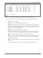
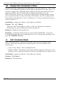
7.2. The Port Diagnostics Screen (/SD)
The Port Diagnostics Screen provides more detailed information about
each port, including most communication parameters. To display the Port
Diagnostics Screen, access the command mode and type /SD [Enter], the
screen will appear as shown in Figure 7.2.
Like the Port Status Screen, the Port Diagnostics Screen is also available in
both Supervisor Mode and non-Supervisor Mode. Note however, that if the
Port Diagnostics Screen command (/SD) is invoked by a password or port that
does not permit Supervisor Mode, then the resulting screen will only display
status of the ports that are specifically allowed by the password entered
at log in.
7-2
The Status Screens
PORT DIAGNOSTICS: APS-M, Version 3.0, Site ID: (undefined)
PORT |
NAME
| STATUS | BAUD | COM | HS | MODE | BUF | CTS
-----+------------------+--------+--------+-----+------+--------+-------+---01 | (undefined)
| *Free | 9600 | 8N1 | RTS | Any
|
0 | H
02 | (undefined)
| Free | 9600 | 8N1 | RTS | Any
|
0 | H
03 | (undefined)
| Free | 9600 | 8N1 | RTS | Any
|
0 | L
04 | (undefined)
| Free | 9600 | 8N1 | RTS | Any
|
0 | L
05 | (undefined)
| Free | 9600 | 8N1 | RTS | Any
|
0 | L
06 | (undefined)
| Free | 9600 | 8N1 | RTS | Any
|
0 | L
07 | (undefined)
| Free | 9600 | 8N1 | RTS | Any
|
0 | L
08 | Internal_Modem
| Free | 9600 | 8N1 | RTS | Modem |
0 | H
Enter /H for command menu.
APS>
Figure 7.2: The Port Diagnostics Screen (Model APS-8M; Defaults Shown)
As shown in Figure 7.2, the Port Diagnostics Screen lists the following:
• Port: The Port Number.
• Name: The user-defined name for each port.
• Status: The connect status for each port. When the port is connected,
this column will list the number of the other port that is connected to this
port. Note that if this column contains an asterisk, this indicates that the
port has accessed command mode.
• Baud: The baud rate selected for each port.
• COM: The Data Bits, Parity, and Stop Bits selected for each port. For
example, "8N1" indicates Eight data bits, No parity, and One stop bit.
• HS: The handshaking (flow control) mode for each port.
• Mode: The user-selected Port Mode. This column will read Any (Anyto-Any), Modem, Passive, or Buffer, depending on the configuration
selected for each port.
• BUF: Lists the amount of data (in bytes) currently stored in the buffer for
this port.
• CTS: The High/Low status of the CTS line at the RS232 interface.
7-3
APS-8M / APS-16M Asynchronous Port Switches; User’s Guide
PORT PARAMETERS #01:
1.
2.
3.
4.
5.
6.
7.
8.
9.
10.
11.
12.
13.
14.
Port Name:
Baud Rate:
Bits/Parity:
Stop Bits:
Handshake Mode:
Port Mode:
64. DTR Output:
Supervisor Mode:
Logoff Character:
Sequence Disconnect:
Timeout Disconnect:
Response Type:
Command Echo:
Accept Break:
Invalid Access Lockout:
(undefined)
9600
8-None
1
RTS/CTS
Any-to-Any
Pulse
Permit
^X
One Character Only
Off
Verbose
On
Yes
Off
APS>
Figure 7.3: The Port Parameters Screen (Port 1 Shown)
7.3. The Port Parameters Screens (/W)
The /W command displays more detailed information about an individual
APS-8/16M port. Rather than listing connection information for all ports like
the Port Status Screens, the Port Parameters screen lists all defined parameters
for a specific port as shown in Figure 7.3.
The /W command is available to both Supervisor Mode and Non-Supervisor
Mode ports and passwords. Note however, that if the /W command is invoked
by a port or password that does not permit access to Supervisor Mode, then the
APS-8/16M will only display information for your resident port.
7.4. The Password Directory Screen (/V)
The Password Directory Screen (Figure 7.4) lists currently defined parameters
for each of the APS-8/16M passwords. Note that the Password Directory
screen will not display actual passwords, and instead, will only indicate
whether or not a password has been defined for each username.
The Password Directory Screen is only available when the Supervisor Mode
is active, and cannot be displayed by ports or passwords that do not permit
Supervisor Access. The APS-8/16M allows for the definition of up to 32
separate passwords.
7-4
The Status Screens
Name
Password
Dial Back #
DB SA
------------------------------------------------------------------------------admin
(defined)
5556789
On On
drafting
(defined)
(undefined)
Off Off
engineering
(defined)
(undefined)
Off On
finance
(defined)
5559900
On Off
hr
(defined)
(undefined)
Off Off
manufacturing
(defined)
(undefined)
Off Off
marketing
(defined)
5551234
On Off
sales
(defined)
5559876
On Off
service
(defined)
5554321
Off Off
test
(defined)
5556789
On On
Reached End of Directory.
APS>
Figure 7.4: The Password Directory Screen (Sample Values Shown)
As shown in Figure 7.4, the Password Directory Screen lists the following:
• Name: The username for each password. Note that the username is not
entered during login, and is used for descriptive purposes only.
• Password: If a password has been defined for the corresponding
username, this column will read "defined"
• Dial Back Number: The number that will be called if the Dial Back
Function is enabled for this password, and the user attempts to access
the APS-8/16M via modem. For more information on the Dial Back
Function, please refer to Section 5.4.2.
• DB (Dial Back): Indicates whether or not the Dial Back Function is
enabled. This column will read "On" if the Dial Back function has been
enabled for the corresponding password.
• SA (Supervisor Access): Indicates whether or not the password will
provide access to the Supervisor Mode. This column will read "On" if the
corresponding password has been granted permission to access Supervisor
Mode.
7-5
APS-8M / APS-16M Asynchronous Port Switches; User’s Guide
7-6
8. Operation
8.1. Any-to-Any Mode
Any-to-Any Mode Ports can be connected to other Any-to-Any, Passive,
Buffer, or Modem Mode Ports by accessing command mode and issuing the /C
Command. All ports can be configured for the Any-to-Any Mode.
8.1.1.
Port Connection and Disconnection
The APS-8/16M provides communication between devices without the
requirement that both devices use the same communication parameters. This
allows you to connect devices that use dissimilar baud rates, parity, handshake,
and etc. The APS-8/16M converts data rates and other parameters, eliminating
the need to select common parameters for all connected devices.
8.1.1.1. Connecting Ports
Two different types of connections can be made between APS-8/16M ports;
Resident Connections and Third Party Connections.
• Resident Connections: Your resident port issues a /C command to
connect to a second port. For example, Port 4 issues the /C command to
connect to Port 5.
• Third Party Connections: (Supervisor Mode Only) Your resident port
issues a /C command to create a connection between two other ports. For
example, Port 1 is your resident port, and Port 1 issues a command to
connect Port 2 to Port 3.
Notes:
• Third Party Connections can only be initiated by ports and
passwords that permit access to Supervisor Mode.
• If a port has accessed command mode using a password that does
not permit Supervisor Mode, then that port will only be able to
connect to the ports that are specifically allowed by the password
definition.
8-1
APS-8M / APS-16M Asynchronous Port Switches; User’s Guide
To connect ports, proceed as follows:
1.
Access command mode as described in Section 5.1. If the Password
Prompt is displayed, enter a password that permits Supervisor Mode.
2.
Invoke the /C command to connect the desired ports.
a)
Resident Connect: To connect your resident port to another port,
type /C xx [Enter]. Where xx is the number or name of the port
you want to connect. The APS-8/16M will display the numbers of
the connected ports, along with the command sequence that will be
required in order to disconnect the two ports.
Example: To connect your resident port to Port 8, type
/C 8 [Enter].
b)
Third Party Connect: (Supervisor Mode Only) To connect any
two ports (other than your resident port), type /C xx XX [Enter].
Where xx and XX are two port names or numbers. The APS-8/16M
will display the numbers of the two connected ports.
Example: To connect Port 5 to Port 6, access command mode using
a password and port that permit Supervisor Mode, and then invoke
the following command: /C 5 6 [Enter].
When the /C command specifies the port name, it is only necessary to enter
enough letters to differentiate the desired port from other ports. Type an
asterisk (*) to represent the remaining characters in the port name. For
example, to connect your resident port to a port named "SALES", the connect
command can be invoked as /C S*, providing no other port names begin with
the letter "S".
8.1.1.2. Disconnecting Ports
There are three different methods for disconnecting ports, the Resident
Disconnect, the Third Party Disconnect, and the No Activity Timeout.
Providing the Timeout feature is enabled, a No Activity Timeout will
disconnect resident ports or third party ports.
Note: When Any-to-Any Mode, Buffer Mode, or Passive Mode are
selected, Option 64 in the Port Parameters Menu determines how the
DTR signal will react when the port disconnects. The DTR signal can
either be held low, held high, or pulsed and then held high.
8-2
Operation
To disconnect ports, proceed as follows:
1.
2.
Resident Disconnect: Disconnects your resident port from another
port. For example, if you are communicating via Port 3, and Port 3 is
connected to Port 4, a Resident Disconnect would be used to disassociate
the two ports. The APS-8/16M offers two different Resident Disconnect
command formats; the One Character Format and the Three Character
Format (for more information, please refer to Section 5.5.3.):
a)
One Character (Default): When the One Character Disconnect
Sequence is selected, simply enter the selected Logoff Character
once (Default = ^X ([Ctrl] plus [X])). Note that it is not necessary
to enter a carriage return before or after the Logoff Character.
b)
Three Characters: Uses the format [Enter]LLL[Enter], where
L is the Logoff Character. For example, if the Logoff Character
is "+", then the three character disconnect sequence would be
[Enter]+++[Enter].
c)
If the default Resident Disconnect Sequence is not compatible with
your application, both the command format and Logoff Character
can be redefined via the Port Configuration menus, as described in
Section 5.5.3.
Third Party Disconnect: (Supervisor Mode Only) The /D command is
issued from your resident port to disconnect two third party ports. For
example, if your Resident Port is Port 1, a Third Party Disconnect could
disconnect Port 3 from Port 4.
a)
The /D command uses the format: /D xx XX [Enter], where xx
and XX are the numbers of the ports that you wish to disconnect.
b)
The /D (Disconnect) command can only be invoked by a port that
permits Supervisor Mode.
c)
The /D command can specify both connected ports, or either of the
two ports. For example, if Port 1 is your resident port, any of the
following commands can be used to disconnect Port 3 from Port 4:
/D 3 4 [Enter]
or
/D 3 [Enter]
or
/D 4 [Enter]
8-3
APS-8M / APS-16M Asynchronous Port Switches; User’s Guide
3.
No Activity Timeout: Providing the Timeout Disconnect feature is
enabled at either connected port, a No Activity Timeout can disconnect
Resident Ports, or Third Party Ports.
a)
RS232 Ports: To configure the Timeout Disconnect Feature
for the RS232 Ports, invoke the /P command to display the
Port Configuration Menu for the desired port as described in
Section 5.5.3. Option 10 enables and defines the Timeout
Disconnect Feature.
b)
When the Timeout Disconnect Feature is enabled, the port will
automatically disconnect if no data is received for the defined
Timeout Period.
Notes:
• When connected ports time out, both ports will exit command mode
after disconnecting.
• When an unconnected port is left in command mode and no
additional data activity is detected, the port will automatically exit
command mode when its defined timeout value elapses.
8.1.2.
Defining Hunt Groups
A Hunt Group creates a situation where the APS-8/16M will scan a group of
ports and connect to the first available port in the group. Hunt Groups are
created by assigning identical or similar names to two or more ports. Hunt
Groups can be defined using Any-to-Any, Passive, Buffer, or Modem Mode
Ports.
1.
Access command mode. If the password prompt is displayed, key in a
password that permits Supervisor Mode.
2.
Invoke the /P command to access the Port Configuration Menu for the
desired Port(s). For example, to configure Port 4, type /P 4 [Enter].
3.
From the Port Configuration Menu, select item 1 to define the Port Name.
4.
Repeat steps 2 and 3 above to assign identical names to the other ports
in the Hunt Group. For example, a series of ports in a group could all be
named "SERVER".
5.
To connect to the next available port in the hunt group, invoke the /C
command using the port name to specify the desired group. For example,
/C SERVER [Enter].
8-4
Operation
6.
Your port will be connected to the first available port in the group. If
all ports are presently connected, the APS-8/16M will respond with a
"BUSY" message.
7.
It is only necessary to enter enough letters of the port name to
differentiate Hunt Group ports from other ports. Type an asterisk (*) to
represent the remaining characters in the port name. For example, to
connect your resident port to the first available port in a group of ports
named "SALES1", "SALES2", and "SALES3", the connect command can
be invoked as /C S* [Enter], providing no other port names begin with
the letter "S".
Hunt Group port names must be unique. Otherwise, ports with similar names
will also be included in the Hunt Group.
Hunt Group Example 1:
1.
Ports 1 and 2 are configured as Modem Mode ports, and external modems
are installed at both ports. Port 1 is named "MODEM1" and Port 2 is
named "MODEM2".
2.
Your resident port is Port 4. To connect to the first available external
Modem, access command mode and type /C MODEM* [Enter].
Hunt Group Example 2:
1.
Ports 3, 4, and 5 are Any-to-Any Mode ports. All three ports are named
"SERVER".
2.
Your resident port is Port 1, and you want to connect Port 2 to the first
available server, access command mode and type
/C 2 SERVER [Enter].
8-5
APS-8M / APS-16M Asynchronous Port Switches; User’s Guide
8.2. Passive Mode
Passive Mode Ports function the same as Any-to-Any Mode Ports, but do not
allow access to command mode. A Passive Mode Port can communicate with
other ports, but cannot enter command mode, and therefore cannot invoke
commands to redefine port parameters, display status, and etc.
Passive Mode Ports can be connected by accessing command mode from a
free Any-to-Any Mode or Modem Mode Port, and invoking the Third Party
Connect or Resident Connect Command as described in Section 8.1.1. Passive
Mode ports will not buffer data, except during baud rate conversion.
Notes:
• A Passive Mode Port is not allowed to access command mode.
• In order to ensure supervisor access to important command
functions, the Passive Mode is not available to Ports 1 and 2
(SetUp Ports).
• The Internal Modem Port cannot be configured as a Passive Mode
Port. On the APS-8M, Port 8 is the Internal Modem Port, and on the
APS-16M, Port 17 is the Internal Modem Port.
8.3. Buffer Mode
Ports configured as Buffer Mode ports will collect data from the connected
device and store it in the APS’s statically allocated memory. Each port features
a fixed length, fixed position data buffer.
The Buffer Mode allows collection of data from various devices without the
requirement that all devices use the same communication parameters (e.g. baud
rate, parity, etc.).
Notes:
• Buffer Mode Ports cannot access command mode.
• In order to ensure supervisor access to important command
functions, the Buffer Mode is not available to Ports 1 and 2
(SetUp Ports).
• The Internal Modem Port cannot be configured as a Buffer Mode
Port. On the APS-8M, Port 8 is the Internal Modem Port, and on the
APS-16M, Port 17 is the Internal Modem Port.
8-6
Operation
8.3.1.
Reading Data from Buffer Mode Ports
To retrieve data from Buffer Mode Ports, you must first determine which port
buffers contain data. To check port buffers for stored data, access command
mode and type /S [Enter] to display the Port Status Screen.
To retrieve data from buffer memory, go to a free Any-to-Any or Modem Mode
Port, access command mode (Supervisor Mode), and issue the /C command
using the following format:
/C xx [Enter]
Where xx is the number or name of the port buffer to be read.
If the port’s buffer is empty, the APS-8/16M will send a message which reads
"Connected xx, Buffer Empty"; where "xx" is the port number. If the buffer
contains data, the APS-8/16M will display a prompt that offers four options:
Next Screen: To scroll through data one screen at a time, press the [Space] bar.
Each time the space bar is pressed, the next full screen of data will be sent.
• Scroll All: To send all data without pausing, press [1].
• Skip/Connect: To connect to the buffer port without sending stored data,
press [2].
• Erase/Connect: To connect to the buffer port and erase stored data,
press [3]. Note that buffered data will be erased immediately and will not
be sent.
Note: All four of these options also allow pass-through
communication with the device connected to the Buffer Mode port.
To clear data from the buffer, use the Erase/Connect option, or go to a free
Any-to-Any or Modem Mode Port with Supervisor Mode capability, and issue
the /E (Erase Buffer) command using the following format:
/E xx [Enter]
Where xx is the number or name of the port buffer to be cleared.
8-7
APS-8M / APS-16M Asynchronous Port Switches; User’s Guide
8.3.2.
Port Buffers
The Status Screen lists the amount of Buffer Memory currently used by each
port. The APS-8/16M uses buffer memory in two different ways, depending
on the user-selected port mode.
• Any-to-Any, Passive, and Modem Mode Ports: When two ports are
communicating at dissimilar baud rates, the buffer memory prevents data
overflow at the slower port.
• Buffer Mode Ports: Stores data received from connected devices.
The user issues a connect command (/C) from an Any-to-Any Mode or
Modem Mode port to retrieve data.
If the Status Screen indicates an accumulation of data, the /E (Erase Buffer)
command can be invoked to clear the buffer.
8.4. Modem Mode
In addition to allowing data transfer, the Modem Mode also provides
additional functions specifically related to modem communication. A Modem
Mode Port can perform all functions normally available in Any-to-Any Mode.
The Modem Mode is available to all RS232 ports. In addition to allowing
configuration of the internal modem, the Modem Mode also simplifies the
process of connecting an external modem to the RS232 Ports.
Note: The Internal Modem Port is always configured for the modem
mode. The Internal Modem Port cannot be configured as an Any-toAny Mode, Buffer Mode or Passive Mode port.
When the Modem Mode is selected, the port configuration menu (command
/P) will display three additional prompts, which allow the user to re-define
the modem reset string, initialization string, and hang-up string. When
Modem Mode is selected for a port that permits Supervisor Mode, you should
also define at least one password that permits Supervisor Mode in order to
discourage unauthorized access to higher command functions.
Normally, when a call is received, the unit will prompt the caller to enter a
password. The APS-8/16M allows three attempts to enter a valid password.
If the correct password is not entered in three attempts, or if the user does
not respond to the password prompt within 30 seconds, the modem will
disconnect. Passwords are defined by invoking the /F command as described
in Section 5.4.
8-8
Operation
Notes:
• When a Modem Mode Port exits command mode, or the DCD line
is lost while command mode is active, the APS-8/16M will pulse the
DTR line to the modem. The unit will then send the user-defined
modem command strings to make certain the modem is properly
disconnected and reinitialized.
• All APS-8/16M RS232 ports can use both the unit’s internal modem
and external modem(s) installed at another RS232 port, providing
that the port password allows access to the desired modem port. To
call out, invoke the /C command to connect to the port, and then
access the modem as you normally would.
• If desired, the Invalid Access Lockout Feature can be configured to
completely shut down a port after a user-defined number of invalid
access attempts are detected. For more information on the Invalid
Access Lockout Feature, please refer to Section 5.5.4.
8-9
APS-8M / APS-16M Asynchronous Port Switches; User’s Guide
8-10
9. Saving and Restoring
Configuration Parameters
After the APS-8/16M has been properly configured, parameters can be
downloaded and saved as an ASCII text file. Later, if the configuration is
accidentally altered, the file with the saved parameters can be uploaded to
automatically reconfigure the unit without the need to manually re-assign
each parameter.
Saved parameters can also be uploaded to other identical APS-8/16M units.
This allows rapid set-up when several units will be configured with the same
parameters, providing that units are the same model (APS-8M or APS-16M)
and are using the same APS-8/16M firmware version.
The "Save Parameters" procedure can be performed from any communications
program (e.g. HyperTerminal, ProComm, Crosstalk, etc.), that allows
downloading of ASCII files.
9.1. Sending Parameters to a File
1.
Start your communications program and access the APS-8/16M command
mode. If the password prompt is displayed, enter a password that permits
access to Supervisor Mode.
2.
When the APS command prompt appears, type /U and press [Enter].
The APS-8/16M will prompt you to configure your communications
program to receive an ASCII download.
a)
Set your communications program to receive an ASCII format
download, and the specify a name for a file that will receive the
saved parameters (e.g. APS8M.PAR).
b)
Disable the Line Wrap function for your terminal emulation
program. This will prevent command lines from being broken in two
during transmission.
3.
When the communications program is ready to receive the file, return to
the APS-8/16M’s Save Parameter File menu, and press [Enter] to proceed
with the download. APS-8/16M parameters will be saved on your hard
drive in the file specified in Step 2 above.
4.
The APS-8/16M will send a series of ASCII command lines which specify
the currently selected APS-8/16M parameters. The last line of the file
should end with a "/G-00" command. When the download is complete,
press [Enter] to return to the "APS>" command prompt.
9-1
APS-8M / APS-16M Asynchronous Port Switches; User’s Guide
9.2. Restoring Saved Parameters
This section describes the procedure for using your communications program
to send stored parameters to the APS-8/16M.
1.
Start your communications program and access the APS-8/16M command
mode; if the password prompt is displayed, enter a password that permits
access to Supervisor Mode.
2.
Configure your communications program to upload an ASCII text file.
3.
Upload the ASCII text file with the saved APS-8/16M parameters. If
necessary, key in the file name and directory path.
4.
Your communications program will send the specified ASCII text file to
the APS-8/16M. When the communications program is finished with the
upload, make certain to terminate the Upload mode.
Note: If the APS-8/16M detects an error in the parameters file, it will
respond with the "Invalid Parameter" message. If an error message is
received, carefully check the contents of the parameters file, correct the
problem, and then repeat the upload procedure.
5.
9-2
If the parameter upload procedure is successful, the APS-8/16M will
send a confirmation message, and then return to the "APS>" command
prompt. Type /S and press [Enter], the APS-8/16M Status Screen will
be displayed. Check the Status Screen to make certain the unit has been
configured with the saved
10. Upgrading APS-8/16M Firmware
When new, improved versions of the APS-8/16M operating firmware become
available, the /UF (Upgrade Firmware) function can be used to update the
APS-8/16M unit to the new firmware version. Updates can be uploaded to the
unit via SetUp Ports one and two, or via the Internal Modem Port. To install a
firmware update, proceed as follows:
Note: All other ports will be disabled during the firmware upgrade
procedure.
1.
Obtain the update file. Firmware modifications can either be mailed to
the customer on a 3.5" diskette or CDROM, or downloaded from WTI via
modem. Place the diskette in your diskette drive and/or copy the file to
your hard drive.
2.
Access the APS-8/16M command mode. If the password prompt is
displayed, key a password that permits Supervisor Mode. The Upgrade
Firmware feature is only available in Supervisor Mode.
3.
When the APS-8/16M command prompt appears, type /UF and then press
[Enter]. The APS-8/16M will display a screen which offers the
following options:
a)
Continue Upload and Keep Current Parameters: To proceed
with the upgrade, while retaining current, user-defined parameters,
type 1 and press [Enter]. All parameter settings will be restored
when the upgrade is complete.
b)
Continue Upload and Default System: To proceed with the
upgrade, and reset parameters to default settings, type 2 and press
[Enter]. When the upgrade is complete, all parameters will be set to
default values. Note that if the Firmware Upgrade is performed via
modem, Modem Port parameters will not be defaulted until after you
hang-up and disconnect from the unit.
c)
Abort Upload: To cancel the upgrade and return to the command
prompt, type 3 and press [Enter].
10-1
APS-8M / APS-16M Asynchronous Port Switches; User’s Guide
4.
Use your communication program’s (e.g. HyperTerminal’s) upload
function to transfer the upgrade firmware to the unit. Select ASCII file
format, and then specify the filename and directory location where the
firmware upgrade file resides.
Note: The Upload function will time-out after one minute of
inactivity. If the function times out, type 1 and press [Enter] to
continue, or press [Esc] to abort.
5.
If the upload is successful, the APS-8/16M will prompt the user to
continue the upgrade or abort.
a)
Upgrade: To continue with the upgrade, type 1 and press [Enter].
APS-8/16M will erase the previous firmware, move new firmware
from data flash to program flash memory, calculate and store the
new checksum, and reboot. Do not attempt to reconnect to the
APS-8/16M until the RDY indicator blinks to indicate the process is
complete.
Note: Do not turn off power to the APS-8/16M unit while the
upgrade is in process.
b)
Abort: To abort the procedure, type 2 and press [Enter].
6.
Incomplete Upload: If the upload is interrupted, times-out, or if the file
is corrupted during transfer, the APS-8/16M will display a screen which
asks for user confirmation before proceeding. To proceed, type 1 and
press [Enter], then return to Step 4 above.
7.
Emergency Recovery: In the rare event that the APS-8/16M operating
system becomes corrupted during installation, front panel indicators will
blink five times and the unit will automatically switch to Emergency
Recovery Mode. Please contact WTI Customer Service for further
instructions.
When firmware upgrades are available, WTI will provide the necessary
files via modem or mailed diskette. At that time, an updated Users Guide or
addendum will also be available.
10-2
11. Command Reference Guide
11.1. Command Conventions
The commands described in this section conform to the following conventions:
• Slash Character: Most APS-8/16M commands begin with the Slash
Character (/).
• Apply Command to All Ports: When the asterisk character is entered as
the argument of the /D command (Disconnect Port), or the /E command
(Erase Buffer) the command will be applied to all ports. For example, to
erase all port buffers, type /E * [Enter].
• Port Name Wild Card: It is not always necessary to enter the entire port
name. Port names can be abbreviated in command lines by entering the
first character(s) of the name followed by an asterisk (*). For example, a
port named "SERVER" can be specified as "S*". Note however, that this
command would also be applied to any other port name that begins with
the letter "S".
• Suppress "Sure?" Prompt: When the /D (Disconnect Port), /E (Erase
Buffer), or /I (Default and Test Unit) commands are invoked, the /Y
option can be included in the command line to override the "Are you Sure
(y/n)?" prompt. For example, to disconnect Port 8 without displaying the
"Sure?" prompt, type /D/Y 8 [Enter].
• Enter Key: All commands are invoked by pressing [Enter].
• Command Mode: APS-8/16M Ports will only recognize commands
when the command mode has been activated. The command mode can
be accessed from a free Any-to-Any or Modem Mode Port. To access the
command mode, proceed as described in Section 5.1.
• Connected Ports: When two ports are connected, most APS-8/16M
commands will not be recognized by either of the connected ports. The
only exception is the Resident Disconnect Sequence (Default = ^X ([Ctrl]
plus [X])).
• Configuration Menus: To exit from most configuration menus, you
must press [Esc]. The only exception to this rule is the Copy Parameters
Menu. For more information on the Copy Parameters Menu, please refer
to Section 5.6.
11-1
APS-8M / APS-16M Asynchronous Port Switches; User’s Guide
11.2. Command Response
When commands are sent to the APS-8/16M, the unit can respond with either
verbose (English Text) or terse messages (numeric / abbreviated). In the
default state, all ports will send verbose command responses.
After the unit is installed and configured, the port configuration command
(/P) can specify an individual response format for each port. In addition to
the Terse and Verbose response modes, the port configuration commands can
also select the Quiet Mode. When the Quiet Mode is selected, the port will not
send messages in response to commands.
The table below summarizes the various response messages for both the Terse
and Verbose modes.
Terse
Verbose
0
OK
0
RAM Test Passed
1
Connected *
2
Busy
3
Disconnected
4
Invalid Command
5
Are You Sure (Y/N) ?
6
Invalid Parameter
7
Invalid Syntax
8
Invalid Access
9
Enter Site ID:
A
Aborted
B
Enter Password:
C
Invalid Password
D
RAM Test Failed at *
E
Inactivity Timeout, Disconnected
F
Data in Buffer from Previous Connection ...
Re-Enter Logoff Sequence to Purge Buffer.
G
Asleep
* These verbose Response Messages include additional information not
provided by terse Response Messages.
11-2
Command Reference Guide
11.3. Command Summary
Command Availability
Function
Command Syntax
Enter Command Mode
[Enter]
Supervisor
Non-Supervisor
X
X
/X [Enter]
X
X
/H [Enter]
X
X
/J [Enter]
X
X
/S [Enter]
X
X
/SD [Enter]
X
X
/W [n] [Enter]
X
X
Display Password
Directory
/V [Enter]
X
Set System Parameters
/F [Enter]
X
/P <x> [Enter]
X
Copy RS232 Port
Parameters
/CP [Enter]
X
Connect
/C <x> [x] [Enter]
X
X
X
X
/D[/Y] <x> [x] [Enter]
/D[/Y] * [Enter]
X
/UL [Enter]
X
/E[/Y] <x> [x] [Enter]
/E[/Y] * [Enter]
X
/U [Enter]
X
Exit Command Mode
Help Menu
Display Site ID
Display Port Status
Display Port Diagnostics
Display Port Parameters
(Who)
Set RS232 Port
Parameters
Resident Disconnect
Third Party Disconnect
Unlock All Ports (Invalid
Access)
Erase Buffer
Default & Test
Save Parameters
Upgrade Firmware
^X
/I[/Y] [Enter]
X
/UF [Enter]
X
Supervisor Mode displays parameters for all ports; Non-Supervisor Mode
only displays parameters for ports allowed by Port Password.
Ports and passwords that do not permit access to Supervisor Mode can
only view parameters for the ports that are specifically allowed by the
password entered at log in.
Ports and passwords that do not permit access to Supervisor Mode are not
allowed to perform a Third Party Connect.
Resident Disconnect: Disconnects your resident port from another port.
Note that the Resident Disconnect Sequence can be redefined via the Port
Configuration Menus.
Third Party Disconnect: Disconnects two or more nonresident ports.
Must be issued from a third port where Supervisor Mode is active.
11-3
APS-8M / APS-16M Asynchronous Port Switches; User’s Guide
11.4. Command Set
This section provides more detailed information on all APS-8/16M commands,
sorted alphabetically by name.
[Enter]
Enter Command Mode
In order to set parameters or connect ports, you must first access command
mode as described in Section 5.1. When command mode is inactive (port
asleep), the port will only respond when the [Enter] key is pressed without any
characters preceding it. If you have defined at least one password that permits
access to Supervisor Mode, the unit will require a password before allowing
access to command mode.
Availability: Supervisor Mode / Non-Supervisor Mode
Format: [Enter] (Press [Enter] twice if other characters have already
been typed.)
Response: The Port Status Screen will be displayed, followed by the
command prompt.
^X Resident Disconnect Sequence
The Resident Disconnect Sequence is issued to disconnect your resident port
from another port. For example, if you are communicating via Port 3, and Port
3 is connected to Port 4, the Resident Disconnect Sequence would be used
to disconnect Port 3 from Port 4. Although the default Resident Disconnect
Sequence is ^X ([Ctrl] plus [X]), the command format and Logoff Character
can also be redefined via the Port Configuration Menus. Note that a three
character disconnect command can also be selected.
Availability: Supervisor Mode / Non-Supervisor Mode
Format: ^X
Response:
Verbose: The APS-8/16M will send the "Disconnected" message, followed
by the Port Status Screen.
Terse: 3
11-4
Command Reference Guide
/C
Connect
Establishes a bidirectional connection between two ports. For more
information and command line examples, please refer to Section 8.1. There
are two types of port connections:
• Resident Connect: If the /C command specifies one port name or
number, your resident port will be connected to the specified port.
• Third Party Connect: If the /C command specifies two port names or
numbers, the unit will connect the two ports indicated. A Third Party
Connect command must be issued from a third port where Supervisor
Mode is active. Passwords and ports that do not permit Supervisor Mode
cannot initiate a Third Party Connect.
Note:
• Passwords and ports that do not permit Supervisor Mode can only
connect to the ports that are specifically allowed by the password
entered at log in.
• Passwords and ports that permit Supervisor Mode can connect to
any free APS-8/16M port.
Availability: Supervisor Mode / Non-Supervisor Mode
Format: /C <x> [x] [Enter]
Where x is the number or name of the port(s) to be connected.
Response:
Verbose: Connected xx, when a Resident Connection is initiated, the
APS-8/16M will also display the currently selected Resident Disconnect
Sequence for your port.
Terse: 1
/CP Copy RS232 Port Parameters
Allows quick set-up when all RS232 ports will be configured with the same or
similar parameters. When the /CP command is invoked, the APS-8/16M will
display a menu that is used to select common port parameters, which can then
be copied to all APS-8/16M RS232 ports. Note that the Copy Command will
not change restricted parameters at Ports 1 and 2 or the Internal Modem Port.
For more information, please refer to Section 5.6.
Availability: Supervisor Mode Only
Format: /CP [Enter]
Response: Displays Copy Parameters Menu
11-5
APS-8M / APS-16M Asynchronous Port Switches; User’s Guide
/D
Third Party Disconnect
Invoke the /D command at your resident port to disconnect two other ports.
The /D command cannot be used to disconnect your resident port. To
disconnect your resident port, issue the Resident Disconnect Sequence or wait
for the Timeout Period to elapse (if enabled).
Availability: Supervisor Mode Only
Format: /D[/Y] <x> [x] [Enter]
Where:
/Y (Optional) suppresses the "Sure?" prompt.
x
Is the number or name of the port(s) to be disconnected.
To Disconnect all ports, enter an asterisk.
Response:
Verbose: "Are you Sure (y/n)?", if Y, unit will respond with
"Disconnected".
Terse: 5, if Y, unit will respond with 3.
Example: To disconnect Port 2 from Port 3 without the "Sure?" prompt,
access command mode using a port and password that permit Supervisor
Mode, and type one of the following commands:
/D/Y 2 [Enter] or /D/Y 3 [Enter]
/E
Erase Buffer
Erases data from the buffer for a specified port or several ports. Note that
erased data cannot be recovered.
Availability: Supervisor Mode Only
Format: /E[/Y] <x> [x] [Enter]
Where:
x
Is the number or name of the port buffer(s) to be cleared.
To erase buffers for all ports, enter an asterisk.
/Y (Optional) Suppresses the "SURE? (Y/N)" prompt.
Response:
Verbose: "Are You Sure (y/n)?", if Y, the unit will respond with "OK".
Terse: 5, if Y, the unit will respond with 0.
Example: To clear the buffer for Port 3, access command mode using a port
and password that permit Supervisor Mode, and type /E 3 [Enter].
11-6
Command Reference Guide
/F
Set System Parameters
Displays a menu which is used to define the Site ID message and other global
parameters. Also allows access to the "Add Password" function. For more
information, please refer to Section 5.4.
Availability: Supervisor Mode Only
Format: /F [Enter]
Response: Displays System Parameters Menu
/H
Help
Displays a Help Screen, which lists all APS-8/16M commands along with a
brief description of each command.
Availability: Supervisor Mode / Non-Supervisor Mode
Format: /H [Enter]
Response: Displays Help Screen. Note that the Supervisor Mode Help Screen
differs from the Non-Supervisor Mode Help Screen.
/I
Default and Test
Tests internal memory and initializes the unit with the default parameters
specified by the SetUp Switches.
CAUTION: When /I is invoked, the APS-8/16M will revert to the
parameters specified by the SetUp Switches. Command selected
parameters will be lost.
Availability: Supervisor Mode Only
Format: /I[/Y] [Enter]
Where /Y is a command option used to suppress the "Sure?" prompt.
Response:
Verbose: "Are You Sure (y/n)?", if Y, memory test and initialization begins.
Terse: 5, if Y, memory test and initialization begins.
/J
Display Site ID
Displays the user-defined Site I.D. message.
Availability: Supervisor Mode / Non-Supervisor Mode
Format: /J [Enter]
Response: Displays Site I.D. Message
11-7
APS-8M / APS-16M Asynchronous Port Switches; User’s Guide
/P
Set RS232 Port Parameters
Displays a menu which allows the user to select options and parameters for
the selected port. Section 5.5.3 describes the procedure for defining port
parameters.
Availability: Supervisor Mode Only
Format: /P [x] [Enter]
Where x is the number or name of the port to be configured. If the
port number or name is not specified, the APS-8/16M will display the
configuration menu for your resident port.
Response: The Port Parameters Menu is displayed.
/S
Display Port Status
Displays the Port Status Screen, which lists current conditions and parameters
for all ports. When the Supervisor Mode is active, the /S command will
display the current status of all APS-8/16M Ports. If the Supervisor Mode is
not active, then the /S command will only display status information for the
ports that are specifically allowed by the password entered at log in. For more
information on the Port Status Screen, please refer to Section 7.1.
Availability: Supervisor Mode / Non-Supervisor Mode
Format: /S [Enter]
Response: Displays Port Status Screen
/SD Display Port Diagnostics
Provides more detailed information regarding the operational status of each
port. If your password and port permit Supervisor Mode, the /SD command
will display status information for all APS-8/16M ports. However, if your
password or port do not permit Supervisor Mode, then the /SD command
will only display information for the ports specifically allowed by your
password. For More information on the Port Diagnostics Screen, please refer
to Section 7.2.
Availability: Supervisor Mode / Non-Supervisor Mode
Format: /SD [Enter]
Response: Displays Port Diagnostics Screen
11-8
Command Reference Guide
/U
Save Parameters
Sends configuration parameters to an ASCII text file as described in Section 9.
Availability: Supervisor Mode Only
Format: /U [Enter]
Response: The APS-8/16M will send a series of command lines.
/UF Upgrade Firmware
When new versions of the APS-8/16M operating firmware become available,
this command is used to update the existing firmware as described in
Section 10. Note that this command will only function at the Internal Modem
Port and at Setup Ports One and Two.
Availability: Supervisor Mode Only
Format: /UF [Enter]
Response: The APS-8/16M will display a menu which offers the options
to retain existing APS-8/16M parameters, default parameters or abort the
upgrade procedure.
/UL Unlock All Ports
Unlocks all ports that have been deactivated by the Invalid Access Lockout
Function. When the /UL command is invoked, the APS-8/16M will unlock all
RS232 ports that are currently in the locked state. For more information on the
Invalid Access Lockout Function, please refer to Section 5.5.4.
Availability: Supervisor Mode Only.
Format: /UL [Enter]
Response: The APS-8/16M will unlock all RS232 Ports.
/V
Display Password Directory
Displays the Password Directory as described in Section 7.4. Note that the /V
command will not display actual passwords, but will instead read "defined" or
"undefined."
Availability: Supervisor Mode Only.
Format: /V [Enter]
Response: The unit will display the Password Directory Screen.
11-9
APS-8M / APS-16M Asynchronous Port Switches; User’s Guide
/W
Display Port Parameters (Who)
Displays detailed configuration information for an individual port. Ports with
User Level command capability cannot display parameters for other ports. If
you have logged into command mode using a port and password that permit
Supervisor Mode, the /W command can display information for any
APS-8/16M port. However, if you have logged into command mode using a
port or password that do not permit Supervisor Mode, the /W command will
only display information for your resident port. For more information, please
refer to Section 7.3.
Availability: Supervisor Mode / Non-Supervisor Mode
Format: /W [x] [Enter]
Where x is the Port number or name. If the "x" argument is omitted,
parameters for your resident port will be displayed.
Response: Displays port parameters.
Example: To display parameters for a port named "SERVER", access the
Command Mode from a port with Supervisor Level command capability, and
type /W SERVER [Enter].
/X
Exit Command Mode
Exits command mode. When issued at the Net Port, also ends the telnet
session. Note that exiting from command mode will not terminate port
connections.
• Any-to-Any Mode: Exits command mode.
• Modem Mode: Disconnects and resets modem, hang-up message is sent,
hardware line to modem drops for 500 ms, and modem reset string is sent.
Availability: Supervisor Mode / Non-Supervisor Mode
Format: /X [Enter]
Response: Disconnected
11-10
A. RS232 Port Interface
Figure A.1: RS232 Port Hardware
DCD and DTR hardware lines function as follows:
1.
2.
When connected:
a)
If either port is set for Modem Mode, the DTR output at either port
reflects the DCD input at the other end.
b)
If neither port is set for Modem Mode, DTR output is held high
(active).
When not connected:
a)
If the port is set for Modem Mode, upon disconnect DTR output is
pulsed for 0.5 seconds and then held high.
b)
If the port is not set for Modem Mode, DTR output is controlled
by the DTR Output option (Parameters Menu, Option 74). Upon
disconnect, Option 74 allows DTR output to be held low, held high,
or pulsed for 0.5 seconds and then held high.
Apx-1
APS-8M / APS-16M Asynchronous Port Switches; User’s Guide
B. Specifications
RS232 Port Interface:
• APS-8M & APS-8M-DC: Seven (7) RS232 serial inputs use DB9
connectors configured as DTE ports.
• APS-16M & APS-16M-DC: Sixteen (16) RS232 serial inputs use DB9
connectors configured as DTE ports.
Internal Modem Interface: RJ11 connectors for connection to your telco line
Coding: Asynchronous, 7/8 bits ASCII.
Parity: Even, Odd, None
Stop Bits: 1 or 2.
Data Rate: 300 to 115.2K bps (standard rates).
Flow Control: XON/XOFF, RTS/CTS, Both, or None.
Timeout: No activity timeout disconnects port. 1, 5, 10, 15, 30 seconds, 1, 5,
15, 30, 90 minutes.
Memory: Stores Parameters and captured data. Non-volatile 32K SRAM
buffer memory per port.
Break: Accept Break or Refuse Break
LEDs: On, Ready, Activity (for each RS232 Port).
Temperature: 0°C to 45°C (operating)
Power:
AC Models: IEC-32 Inlet, 115/230 VAC, 50/60 Hz, 5 watts
DC Models: Terminal Strip, -48 VDC, 0.2 Amp Max.
Size: 1.7” High x 17.15” Wide x 6.8” Deep (One Rack Unit)
Weight: 8 lbs. shipping weight
Humidity: 10 to 90% RH, Non-Condensing
Venting: Side vents are used to dissipate heat generated within the unit.
When mounting the unit in an equipment rack, make certain to allow
adequate clearance for venting.
Apx-2
Appendices
C. Customer Service
Customer Service hours are from 8:00 AM to 5:00 PM, PST, Monday through
Friday. When calling, please be prepared to give the name and make of the
unit, its serial number and a description of its symptoms. If the unit should
need to be returned for factory repair it must be accompanied by a Return
Authorization number from Customer Service.
WTI Customer Service
5 Sterling
Irvine, California 92618
Local Phone: (949) 586-9950
Toll Free Service Line: 1-888-280-7227
Service Fax: (949) 457-8138
Email: [email protected]
Apx-3
APS-8M / APS-16M Asynchronous Port Switches; User’s Guide
D. Trademark and Copyright Information
WTI and Western Telematic are trademarks of Western Telematic Inc.. All
other product names mentioned in this publication are trademarks or registered
trademarks of their respective companies.
Information and descriptions contained herein are the property of Western
Telematic Inc.. Such information and descriptions may not be copied,
disseminated, or distributed without the express written consent of Western
Telematic Inc..
© Copyright Western Telematic Inc. 2005.
Printed in the United States of America.
March, 2005
Part Number: 13202, Revision: D
Trademarks Used in this Manual
ProComm and ProComm Plus are registered trademarks of Datastorm
Technologies, Inc.
HyperTerminal is a registered trademark of Hilgraeve, Inc.
Apx-4
Appendices
E. Regulatory Statements
FCC Part 15 Regulation
This equipment has been tested and found to comply with the limits for a Class A digital device,
pursuant to part 15 of the FCC Rules. These limits are designed to provide reasonable protection
against harmful interference when the equipment is operated in a commercial environment. This
equipment generates, uses, and can radiate radio frequency energy and, if not installed and used in
accordance with the instruction manual, may cause harmful interference to radio communications.
Operation of this equipment in a residential area is likely to cause harmful interference in which
case the user will be required to correct the interference at his own expense.
This device complies with part 15 of the FCC Rules. Operation is subject to the following two
conditions: (1) This device may not cause harmful interference, and (2) this device must accept
any interference received, including interference that may cause undesired operation
WARNING: Changes or modifications to this unit not expressly approved by the
party responsible for compliance could void the user’s authority to operate the
equipment
FCC Part 68 Statement
General Requirements For All Equipment:
This equipment complies with Part 68 of the FCC rules. On the back cover of this equipment is a
label that contains, among other information, the FCC registration number and ringer equivalence
number (REN) for this equipment. If requested, this information must be provided to the telephone
company.
A plug and jack used to connect this equipment to the premises wiring and telephone network
must comply with the applicable FCC Part 68 rules and requirements adopted by the ACTA. A
compliant telephone cord and modular plug is provided with this product. It is designed to be
connected to a compatible modular jack that is also compliant. See installation instructions for
details.
The REN is used to determine the number of devices that may be connected to a telephone line.
Excessive RENs on a telephone line may result in the devices not ringing in response to an
incoming call. In most but not all areas, the sum of RENs should not exceed five (5.0). To be
certain of the number of devices that may be connected to a line, as determined by the total RENs,
contact the local telephone company.
If this equipment (analog modem) causes harm to the telephone network, the telephone company
will notify you in advance that temporary discontinuance of service may be required. But if
advance notice isn’t practical, the telephone company will notify the customer as soon as possible.
Also, you will be advised of your right to file a complaint with the FCC if you believe it is
necessary.
The telephone company may make changes in its facilities, equipment, operations or procedures
that could affect the operation of the equipment. If this happens the telephone company will
provide advance notice in order for you to make necessary modifications to maintain uninterrupted
service.
Apx-5
APS-8M / APS-16M Asynchronous Port Switches; User’s Guide
If trouble is experienced with this equipment, for repair or warranty information, please contact
Western Telematic, Inc. at 1-800-854-7226. If the equipment is causing harm to the telephone
network, the telephone company may request that you disconnect the equipment until the problem
is resolved.
Connection to party line service is subject to state tariffs. Contact the state public utility
commission, public service commission or corporation commission for information.
If your home has specially wired alarm equipment connected to the telephone line, ensure the
installation of this equipment does not disable your alarm equipment. If you have questions about
what will disable alarm equipment, consult your telephone company or a qualified installer.
EMC, Safety, and R&TTE Directive Compliance
The CE mark is affixed to this product to confirm compliance with the following European
Community Directives:
• Council Directive 89/336/EEC of 3 May 1989 on the approximation of the laws of Member
States relating to electromagnetic compatibility;
and
• Council Directive 73/23/EEC of 19 February 1973 on the harmonization of the laws of
Member States relating to electrical equipment designed for use within certain voltage
limits;
and
• Council Directive 1999/5/EC of 9 March on radio equipment and telecommunications
terminal equipment and the mutual recognition of their conformity.
Industry Canada
This Class A digital apparatus complies with Canadian ICES-003.
Cet appareil numérique de la classe A est conforme à la norme NMB-003 du Canada.
This product meets the applicable Industry Canada technical specifications
The Ringer Equivalence Number is an indication of the maximum number of devices allowed
to be connected to a telephone interface. The termination on an interface may consist of any
combination of devices subject only to the requirement that the sum of the RENs of all the devices
does not exceed five
Apx-6
Index
Accept Break
Activity LEDs
AC Powered Units
Adding Passwords
Add Name/Password
Dial Back Number
Name
Password
Port Access
Supervisor Mode
Any-to-Any Mode
AT Commands
Baud Rate
Bits
Breaks
Buffer Mode
Port Buffers
Reading Data
A
B
C
CLEAR Button
Command Echo
Command Mode Access
Local
Modem
Command Reference Guide
Command Response
Command Set
Command Summary
Configuration
Connecting Ports
Connecting Power
Connect Command
Copying Parameters
Copy Parameters
Customer Service
D
Data Bits
DCD Indicator
DC Powered Units
Default and Test
Default Parameters
Reset
Delete Password Directory
Diagnostics Screen
Dial Back Attempts
Dial Back Delay
Dial Back Function
5-16
2-1
4-1
5-6
5-5
5-6
5-6
5-6
5-7
5-6
5-11
6-1 to 6-4
5-13
5-13
5-16
5-1, 5-11, 8-6
8-8
8-7
2-1
5-16
5-1 to 5-2
5-1 to 5-2
11-1 to 11-10
11-2
11-4
11-3
5-1 to 5-20
8-1 to 8-2
4-1
11-5
5-18
11-5
Apx-3
5-13
2-1
4-1
11-7
2-1
5-8
7-2
5-4
5-4
5-8 to 5-9
Dial Back Mode
Dial Back Number
Disconnecting Ports
DTR Output
DTR Signal
Duplex Mode
5-6
5-6
8-2 to 8-3
5-13
Apx-1
5-16
E
Edit/Delete from Search
Edit/Delete from List
Edit Password
EMC Information
Enter Command Mode
Erase/Connect
Erase Buffer Command
Exit Command Mode
Firmware Upgrade
Flow Control
Grounding
Handshake Mode
Hang-Up String
Help Menu
Hunt Groups
F
G
H
I
Initialization String
Internal Modem
Invalid Access Lockout
Lockout Access
Lockout Attempts
Lockout Duration
Unlock Ports
Line Port
Lockout Access
Logoff Character
L
M
Modem Command Mode
Modem Mode
Hang-Up String
Initialization String
Reset String
Modem Port
5-5 to 5-6
5-5
5-7
Apx-6
11-4
8-7
11-6
11-10
10-1 to 10-2, 11-9
5-13
i
5-13
5-14
11-7
8-4 to 8-5
5-14
6-1 to 6-4
5-16 to 5-17
5-17
5-17
5-17
11-9
2-2, 4-2
5-17
5-15
6-1
5-11, 8-8
5-14
5-14
5-14
2-2, 4-2
Index-1
APS-8M / APS-16M Asynchronous Port Switches; User’s Guide
Name
No Activity Timeout
N
O
One Character Disconnect
ON Indicator
Operation
P
5-6
8-4
5-15, 8-3
2-1
8-1 to 8-9
Parameters
Saving and Restoring
9-1 to 9-2
Parity
5-13
Passive Mode
5-1, 5-11, 8-6
Passwords
5-2 to 5-4
Adding
5-6 to 5-7
Editing and Deleting
5-7 to 5-8
Password Directory
5-4 to 5-6, 11-9
Add Name/Password
5-5 to 5-6
Delete Entire Directory
5-5
Deleting Entire
5-8
Edit/Delete from List
5-5 to 5-6
Edit/Delete from Search
5-5
Password Directory Screen
7-4 to 7-5
Password on Dial Back
5-4
Pinout
Apx-1
5-7
Port Access
8-8
Port Buffers
5-10 to 5-19
Port Configuration
Accept Break
5-16
Baud Rate
5-13
Command Echo
5-16
Conventions
5-10
Copying Parameters
5-18
Data Bits
5-13
DTR Output
5-13
Handshaking
5-13
Hang-Up String
5-14
Initialization String
5-14
5-16 to 5-17
Invalid Access Lockout
5-15
Logoff Character
Parity
5-13
Port Mode
5-13
Port Modes
5-11
Port Name
5-13
Reset String
5-14
5-16
Response Type
Sequence Disconnect
5-15
Supervisor Mode
5-15
5-16
Timeout Disconnect
Port Connection
4-2, 8-1 to 8-2
Resident Connections
8-1
Third Party Connections
8-1
Port Diagnostics
11-8
Port Diagnostic Screen
7-2
Port Disconnection
8-2 to 8-3
Index-2
Port Interface
Port Mode
Port Modes
Any-to-Any Mode
Buffer MOde
Buffer Mode
Modem Mode
Passive Mode
Port Name
Port Parameters
Port Parameters Screens
Port Status
Port Status Screen
Power Components
Power Supply
R
Rack Mounting
RDY Indicator
Reading Data
Reset Default Parameters
Reset String
Resident Connections
Resident Disconnect
Response Type
Restoring Parameters
RS232 Ports
Configuration
S
Apx-1
5-13
5-11
5-11
5-11
8-6 to 8-7
5-11, 8-8
5-11, 8-6
5-13
11-8, 11-10
7-4
11-8
7-1 to 7-2
2-2
i, 4-1
i
2-1
8-7
2-1
5-14
8-1
5-15, 8-3, 11-4
5-16
9-2
2-2, Apx-1
5-12 to 5-17
Save Entry
5-7
Saving Parameters
9-1, 11-9
8-7
Scroll All
Sequence Disconnect
5-15
Serial Ports
2-2
2-1
SET Button
Set Up Ports
5-2
Site I.D. Message
5-4, 11-7
Skip/Connect
8-7
Slash Character
11-1
Apx-2
Specifications
Status Screens
7-1 to 7-5
Password Directory Screen
7-4
Port Diagnostic Screen
7-2 to 7-3
Port Parameters Screens
7-4
Port Status Screen
7-1 to 7-2
Stop Bits
5-13
Supervisor Mode
5-1, 5-2, 5-6, 5-15
Sure Prompt
11-1
System Parameters
5-3 to 5-9, 11-7
5-4
Dial Back Attempts
Dial Back Delay
5-4
Password Directory
5-4 to 5-7
Password on Dial Back
5-4
Site I.D. Message
5-4
Index
T
Terminal Block
Terse Response
Third Party Connections
Third Party Disconnect
Three Character Disconnect
Timeout
Timeout Disconnect
Unlocking Ports
Unlock Ports
Upgrade Firmware
Upgrading Firmware
User Name
Verbose Response
U
V
W
Warnings and Cautions
Who Command
4-1
5-16, 11-2
8-1
8-3, 11-6
5-15, 8-3
8-4
5-16
5-17
11-9
11-9
10-1 to 10-2
5-6
5-16, 11-2
ii
11-10
Index-3
APS-8M / APS-16M Asynchronous Port Switches; User’s Guide
Index-4
5 Sterling • Irvine • California 92618
(949) 586-9950 • Toll Free: 1-800-854-7226
Fax: (949) 583-9514 • http://www.wti.com