1
TABLE OF CONTENTS
CHAPTER 1: INTRODUCTION
1.0 ABOUT ADAT ....................................................................................5
1.2 IMPORTANT NOTE ABOUT THIS MANUAL ..................................9
1.3 OVERVIEW OF MAIN FUNCTIONS ...............................................10
1.3A Transport ..............................................................................10
1.3B Record/Monitor functions ....................................................10
1.3C Punching..............................................................................10
1.3D Autolocation..........................................................................11
1.3E LED Indicators ....................................................................11
1.4 “ENGAGED” VS. “DISENGAGED” TAPES .................................11
1.5 A WORD ON ADAT's S-VHS CASSETTE TAPE..........................12
1.6 OPERATING ENVIRONMENT ........................................................13
1.6A Thermal Considerations in Rack Mounting ..........................13
1.6B Mounting on a Shelf or Non-Rack Enclosure......................13
1.6C Avoiding Electromagnetic Interference ...............................13
CHAPTER 2: HOOKUP
2.0 POWER .............................................................................................15
2.0A The AC Cord........................................................................15
2.0B Avoiding Ground Loops .......................................................16
2.1 AUDIO CABLE TIPS........................................................................17
2.2 AUDIO—UNBALANCED INPUTS..................................................18
2.2A Input Jack Characteristics ..................................................18
2.2B Typical Input Jack Hookups................................................19
2.2C Special Unbalanced Input Jack Wiring ...............................19
2.3 AUDIO—UNBALANCED OUTPUTS..............................................20
2.4 AUDIO—BALANCED INPUTS AND OUTPUTS ...........................21
2.5 DIGITAL I/O ......................................................................................21
2.6 SYNC.................................................................................................21
2.7 METER BRIDGE...............................................................................22
2.8 FOOTSWITCHES .............................................................................22
CHAPTER 3: GETTING READY TO RECORD
3.0 POWER-UP AND TAPE INSERTION.............................................23
3.1 FORMATTING A TAPE
...........................................................23
3.1A To Format A New Tape, or
Reformat/Erase an Old Tape..............................................24
3.1B To Extend a Format.............................................................25
3.1A Additional Format Considerations ........................................26
3.1B Record A “Benchmark” Tape ..............................................27
3.2 TRACK RECORD/MONITOR CONTROLS....................................27
3.2A Record Enable Buttons .......................................................27
3.2B Auto Input Monitor................................................................27
3.2C All Input Monitor...................................................................29
3.2D Digital Input..........................................................................29
3.3 SETTING LEVELS............................................................................29
3.4 TRANSPORT CONTROL OPERATION.........................................31
3.4A Eject.....................................................................................31
3.4B Rewind.................................................................................31
3.4C Fast Forward .......................................................................31
3.4D Stop .....................................................................................32
3.4E Play .....................................................................................32
3.4F Record/Punch In or Out......................................................33
3.5 FOOTSWITCH-CONTROLLED PUNCHING ................................34
CHAPTER 4: PITCH, AUTOLOCATION, AND REMOTE CONTROLS
4.0 PITCH CONTROLS..........................................................................35
4.1 AUTOLOCATION CONTROLS.......................................................36
4.1A Setting Locations .................................................................36
4.1B Autolocating to One of the Three Location Points...............37
4.1C Shuttling Between Locate 1 and 2.......................................37
4.1D The Auto Play Function........................................................38
4.1E Record, Then Audition Your Part ........................................38
4.2 FOOTSWITCH CONTROLLED AUTOLOCATION .......................38
4.3 USING THE LRC REMOTE CONTROL .........................................39
CHAPTER 5: MULTIPLE ADAT OPERATION
5.0 MULTIPLE ADAT BASICS41
5.1 SYNCHRONIZING MULTIPLE ADATS ..........................................42
5.1A Hooking Up Multiple ADATs.................................................42
5.1B ADAT ID (Identification) Numbers.......................................42
5.1C How the Master and Slave Decks Interact.........................43
5.1D Achieving Lock .....................................................................44
5.1E Independent Slave Mode......................................................44
5.2 FORMATTING WITH MULTIPLE ADAT SYSTEMS ......................44
5.2A Master Format Enabled and
Performing a Complete, Start-to-Finish Format...................44
5.2B Master Format Enabled and
Extending the Format...........................................................45
5.2C Master Format Disabled......................................................45
5.3 AUTO-LOCATION/LOOPING
WITH MULTIPLE ADATS ................................................................47
CHAPTER 6: BACKUP
6.0 BACKUP BASICS............................................................................49
6.1 BACKING UP VIA DIGITAL I/O ......................................................49
6.1A Normal Method .....................................................................50
6.1B Optical-Only Method............................................................52
6.2 BACKING UP VIA ANALOG I/O.....................................................53
CHAPTER 7: APPLICATIONS
7.0
7.1
7.2
7.3
7.4
COMBINED MULTITRACK/ MASTERING DECK .........................55
ARCHIVING ......................................................................................55
BOUNCING.......................................................................................56
LIVE RECORDING...........................................................................56
USING ADAT WITH MIDI SEQUENCERS
VIRTUAL TRACKING ......................................................................56
7.6 VIDEO LOCATION RECORDING...................................................57
7.7 MODULAR RECORDING 57
CHAPTER 8: ADAT ADVANCED FEATURES
8.0 ABOUT THE ADVANCED FEATURES..........................................59
8.1 ADVANCED FEATURES 59
8.1A Eject the tape in the Master ADAT of a Multi
ADAT System .....................................................................60
8.1B Device Id.............................................................................60
8.1C Auto Input Monitor Option Select ........................................60
8.1D Software Version.................................................................60
8.1E Tape Write Protect Status ..................................................60
8.1F Monitor/Audio Path Select ..................................................61
8.1G Crossfade Select ...............................................................61
8.1H Digital 48k Master Clock Enable/Disable............................62
8.1I Total Running Time of Drum Motor......................................62
CHAPTER 9: MAINTENANCE/SERVICE
9.0 GENERAL INFORMATION63
9.0A Cleaning...............................................................................63
9.0B Maintenance .......................................................................63
9.0C Refer All Servicing to Alesis................................................63
9.1 ADAT HEAD LIFE ............................................................................64
9.2 ADAT HEAD MAINTENANCE ........................................................64
9.3 TAPE MAINTENANCE - SAFE TAPE ............................................66
9.4 ERROR MESSAGES .......................................................................67
9.4A ADAT Messages and Explanation ......................................68
9.4B Errors 1 to 9........................................................................69
9.4C Steps to Take Before Calling for Help................................71
CHAPTER 10: APPENDICES ..............................................................
10.0 APPENDIX 1
DIGITAL RECORDING—A QUICK TOUR.................................73
10.0A Analog Tape Recording Basics........................................73
10.0B Digital Tape Recording Basics ........................................74
10.0C Why Does ADAT Use S-VHS Cassettes?......................74
10.1 APPENDIX 2
GLOSSARY..................................................................................76
10.2 APPENDIX 3
SPECIFICATIONS .......................................................................80
10.3 APPENDIX 4
SCHEMATICS ..............................................................................83
CHAPTER 1: INTRODUCTION
1.0 ABOUT ADAT
Congratulations. You've just purchased an incredible piece of recording equipment.
Here are a few of the features that make the ADAT Digital Recorder perhaps one of
the most important advances in recording technology since the invention of multitrack. These features are of equal significance to the professional commercial studio
and the personal home or project studio:
•
Low tape cost. ADAT records approximately 40 minutes of audio on a standard
S-VHS® tape cassette. This is the same tape that is used with S-VHS video tape
recorders. It's readily available and relatively low in cost for the purpose of multitrack recording. We chose S-VHS because the cassette shell, tape hubs and
guides are precision crafted in the S-VHS format to treat the tape gently and
interface in a precisely controlled manner with the ADAT transport over long
periods of recording. We recommend you always use S-VHS tape to protect your
valuable recordings. Your ADAT was packed with a complimentary Alesis S-VHS
Mastering Audio Cassette. It should perform to your highest expectations. You
can order more through your Alesis dealer or directly from Alesis. See the
accompanying flyer for information on how to order.
•
Superb fidelity. ADAT uses 16-bit linear analog-to-digital conversion, the
professional standard 48 kHz sampling rate (variable from 40.4kHz to 50.85kHz),
and 64 times oversampling for better-than-CD quality sound.
•
Ultra high fidelity digital converters. The digital converters in ADAT are the
latest generation in converter technology.
® VHS is a registered trademark of JVC.
Because of the tremendous economies of scale realized in manufacturing ADAT,
these high quality and
more expensive converters are included in the ADAT design (rather than having to
be purchased as a separate accessory box as with some recorders) in spite of
ADATs low overall cost. This converter technology allows recording and
reproduction of the very highest quality. Plus, ADAT's design dedicates separate
converters to the inputs and outputs of each individual track. That's 16 converters
in all - no multiplexing.
•
Easy and familiar front panel controls. If you've ever used a multitrack tape
recorder, then you probably already know how to use ADAT. Familiar controls
like play, record, fast forward, rewind, and track select buttons perform the majority of functions you'll need. There are no difficult engineering routines for you to
learn.
•
Sample accurate syncing capabilities. ADAT was designed to work perfectly
as a stand-alone 8 track recorder and performs this function without equal. But
its design goes much further to include a built in synchronization system that
allows multiple ADATs to lock together in perfect synchronization; so, you can
expand the number of recording tracks and buy more ADATs as your budget
allows and your needs expand. Nothing in the system will become obsolete and
ADAT's modular standard is the key to compatability between your studio and
everyone else's; be it a home studio or fully professional commercial studio. You
might have purchased 3 or four ADATS and the optional BRC Remote Control for
a 24 or 32 track system, or you might even plan to build a large ADAT system of
up to 16 ADATS and the BRC- that's 128 tracks of digital audio! Multiple ADATs,
the BRC and other accessories (like the RMB Remote Meter Bridge) form what
we call the ADAT System.
Each ADAT tape is "formatted" (a simple operation that can be done before or
during recording) with a proprietary Alesis time code that is much more accurate
than SMPTE or other time code systems, and time-stamps the tape to an
incredible single-sample accuracy; that is, 1/48,000th of a second.
Why is this important? Because of such incredibly tight sync performance,
multiple ADATs are virtually free of the evils of incoherent phase between tracks
playing on different machines. This means that when you lock 2 or more ADATs
together, you're really creating the equivalent of one large digital tape recorder
and one very wide, seamless piece of tape.
And because ADAT's sync system is internalized and so accurate, you get
machine synchronization without giving up an audio track, accurate tape counter
readings without annoying slippage, and intelligent sample-accurate autolocation
functions with the BRC.
•
Modular recording. This is the feature that makes ADAT and the ADAT System
perhaps the most flexible multitrack recorder ever designed. Because ADAT's SVHS tape format is so inexpensive, you can easily record alternate versions of
vocals, solos, background accompaniments; whatever your creative urge
dictates.
Modular recording means you can build as many tracks as you desire while
you're recording and do composite editing with the BRC and ADAT's Optical
Digital Interface (see next section) before the final mixdown.
•
Optical digital interface. In addition to conventional analog inputs and outputs, a
“master” digital I/O carries all eight tracks simultaneously via optical cable,
allowing for perfect, degradation-free digital dubbing between ADATs. And with
the addition of the optional BRC Remote Control, you can assign any part of any
track to any other track in a multiple ADAT system. This means you can do
complex composite editing. Like the chorus on track 2? Want to replace the chorus on track 15? Easy to do with the BRC carrying the timing and Sync
Information while the optical cable carries all the digital audio. The new chorus on
track 15 will be an exact digital duplicate of the one on track 2. Feel particularly
inspired one day, but can't make up your mind about which lead solo to go with?
Fill five or six tracks of a single S-VHS cassette tape with your hottest playing.
Take the best performance, or the best parts of each one and recompose the
entire solo on a new track. All in perfect sync, all sample accurate, all in the digital
domain. The popular recording practice of composite vocals is just as easy, and
more effective than ever with ADAT to support your efforts.
•
AI-1 AES/EBU and S/PDIF Digital Interface with Sample Rate Converter. If
you need to integrate your ADAT recordings with digital recording equipment from
other manufacturers, an optional accessory box, the Alesis AI-1, can isolate the
digital audio signal 2 tracks at a time from the optical interface's 8-track data
stream, and assign that pair to the industry standard AES/EBU and S/PDIF
interfaces. This allows for direct digital connection, with sample rate conversion,
to and from other digital audio recorders, DAT recorders, CDs, hard disk
recorders, synthesizers, and more.
•
LRC Remote Control. Each ADAT is supplied with the LRC Remote. This handy
device duplicates ADAT's front panel play, record, fast forward, rewind, stop and
3 point autolocate system. You can also control the monitor select functions.
•
Highly sophisticated and comprehensive optional BRC Master Remote
Control. The BRC is the brains of the ADAT System. It supplies sophisticated
synchronization and overdubbing functions for multiple ADAT machines, remote
control of virtually all recorder functions, reads and generates SMPTE time code,
and generates MIDI Time Code (MTC) and MIDI clocks. The BRC can control up
to 16 ADATs for a total of 128 tracks of digital audio.
•
RMB Remote Meter bridge option. When using the BRC in a multi-ADAT
system the RMB Remote Meter Bridge provides localized viewing of 32 channels
of LED meters. It's designed to mount on top of the BRC (or be rack mounted) so
that you can install your ADATs in a remote rack and control functions and view
critical metering of the recorders directly from one location.
•
Easy interfacing with professional, project and home studios.
ADAT includes a balanced 56 pin ELCO connector for +4dBu interfacing, typical
in professional studios. For the home and project studio using -10 signals, ADAT
includes unbalanced -10dBV inputs and outputs on 1/4" jacks. For convenience,
the balanced and unbalanced inputs and outputs work simultaneously.
•
Voltage-tolerant power supply. ADAT accepts any AC
voltage between 90 and 250 volts, without the need for external converters.
•
Compatibility with multi-channel mixdown formats. ADAT
is ideal for quadraphonic, surround, and theatrical sound applications that require
more than two channels for the final master.
For more information on digital recording, see Appendix 1. Appendix 2 is a glossary
of digital recording-related terms that may be helpful as you read this manual.
1.2
IMPORTANT NOTE ABOUT THIS MANUAL
ADAT’s transparent user interface may tempt you to just plug in and start recording.
We can certainly understand your excitement, but please at least do the following:
1.3
•
Read section 1.4 on the difference between “engaged” and
“disengaged” tapes, and section 3.1 on formatting tapes (with multiple ADAT
systems, also refer to section 5.2). These important sections describe recording
concepts that have no counterpart with analog recorders, and which must be
understood before you start using ADAT.
•
Please read the entire manual at some point to acquaint yourself with the many
ADAT features that you’ll know about only if you read the manual.
OVERVIEW OF MAIN FUNCTIONS
Here is a brief rundown of ADAT’s main functions.
1.3A Transport
The transport is like most standard multitrack recorder transports. Tape motion
controls include play, fast forward, rewind, stop, record, and pause. The counter
shows elapsed time from the beginning of the tape, or the time from where you last
reset the zero counter.
1.3B Record/Monitor functions
ADAT does much of the recording/monitoring switching work for you. Generally,
tracks monitor what’s on tape until you initiate recording (typically by punching), at
which point any tracks set to record monitor the inputs so you can hear what’s being
recorded. For live multitrack recording, a special mode lets you monitor all eight
inputs regardless of record status.
The input jacks are wired using innovative switching techniques to allow for fast track
selection, patching, and track switching. Section 2.2C explains this in more detail.
1.3C Punching
Punch-in and punch-out are gapless and glitchless. Digital crossfades can be set to
any of four different crossfade times.
A user-supplied momentary footswitch allows for no-hands punch-in and out.
The BRC can do auto punch in and out referenced to sample-accurate location points.
1.3D Autolocation
You can set three autolocate points on the front panel or on the LRC Remote; simply
pressing a button will cause ADAT to seek and find the desired point. “Looping” is
also possible by shuttling between two locate points. An auto play feature can
automatically put ADAT into play mode when the autolocation operation is complete.
1.3E LED Indicators
In addition to specific LED indicators (such as those that indicate if a track is recordenabled), several switches have built-in LEDs. Sometimes these flash to indicate that
a function is ready to be initiated, then turn solid to indicate that the function is being
implemented. Most switches toggle, meaning that pressing once will turn a function
on, and pressing again will turn it off.
In this manual, LEDs are spelled with all capital letters (such as RECORD LED or
FORMAT LED).
1.4
“ENGAGED” VS. “DISENGAGED” TAPES
When you first insert an S-VHS tape cassette into ADAT,
a portion of the tape is pulled out of the tape cartridge and threaded against a rotating
head drum where the digital information is actually read and recorded in diagonal
scans across the tape. This is called engaged mode. Even when the tape itself is
stopped, it is still in contact with the head drum. If the STOP LED is lit solid, the tape
is engaged.
This allows for going into play or record faster, as well as “cue” and “review”
functions that let you monitor the tape audio during fast forward and rewind. When the
machine is paused, the head remains spinning, and the tape is not disengaged from
the head.
If you press the Stop button twice, the ADAT mechanism will unthread the tape and pull it
back into the S-VHS cassette. The STOP LED will blink to indicate that the tape is
disengaged.
When the tape is “disengaged,” the head is not spinning and it takes slightly longer to go
into play or record. Cue and review are no longer possible, but rewind and fast forward
speeds are much faster.
As a general rule, if you need to fast forward or rewind over a long length, disengage the
tape first; if you only need to fast forward or rewind a short distance, leave the tape
engaged.
If the tape is engaged, and no transport activity (play, record, rewind, etc.) occurs
within about 4 minutes, the tape will automatically disengage itself to minimize tape
wear.
1.5
1.6
A WORD ON ADAT’s S-VHS CASSETTE TAPE
•
Use only premium quality, name brand S-VHS cassette tape in the ST-120 length.
Alesis cannot overstress the importance of this. We recommend using AMPEX 489
DM Digital Mastering Audio Tape, or Alesis ADAT Mastering Audio Cassettes.
Other acceptable brands include Maxell XR-S Black, JVC XZ, 3M Master
Broadcast and ASD 40+, and TDK SP Super Pro.
•
We do not recommend that you use inexpensive,
budget VHS cassettes. While they may work technically, their unpredictable quality and less
than premium formulation could decrease the reliability of your recording. Don't trust your
music with anything less than premium S-VHS tape. Inferior tapes not only jeopardize the
recordings made on them, they may shed oxide and leave behind a coating of dirt that will
interfere with future recordings, even if you switch back to premium quality tape. Defective
tape may even clog the head, requiring service.
•
Accidents can happen—so digital audio, like floppy disks and hard disks, should
be backed up to prevent loss. Back up your tapes to another ADAT using the
fiber optic digital connector (section 6.1).
•
Treat your tapes as the precision, fragile components that they are. Do not
expose them to extremes of heat, cold, or humidity. Never place tapes near
magnetic fields (power amps, TVs, monitors, magnets, etc.), and handle tapes
gently.
OPERATING ENVIRONMENT
1.6A Thermal Considerations in Rack Mounting
ADAT can be mounted in an equipment rack (taking up 3 rack spaces) or placed on
a table or shelf. When you install it, keep in mind that heat is the major enemy of
electronic equipment. Please observe the following:
•
ADAT is designed to perform properly over a range of ambient temperatures from
10° C to +40° C (50° F to 104° F), in up to 80% non-condensing humidity. These
are not absolute limits, but Alesis cannot guarantee that ADAT will meet its
published specs or remain reliable if operated outside of these ranges.
•
Always allow adequate ventilation behind ADAT. Do not seal any enclosure that
holds ADAT. It is not necessary to leave an empty rack space above or below
ADAT unless it runs hot enough to affect equipment above or below it.
1.6B Mounting on a Shelf or Non-Rack Enclosure
To mount ADAT on a shelf or other flat surface, Alesis recommends using the
enclosed stick-on feet to avoid scratching the shelf’s surface with the deck’s bottom.
Please observe the general comments on thermal considerations given under
“Thermal Considerations in Rack Mounting” no matter where or how the deck is
mounted.
1.6C Avoiding Electromagnetic Interference
Like all tape machines, ADAT uses magnetic tape that can be sensitive to
electromagnetic interference. Generally this is not a problem, but avoid
mounting ADAT next to devices that generate strong magnetic fields such as
power amplifiers, monitors and video display devices, speakers, etc.
CHAPTER 2: HOOKUP
2.0
POWER
2.0A The AC Cord
ADAT works with any AC voltage from 90 to 250 volts, 50 or 60 Hz. ADAT comes
with a line cord suitable for the destination to which ADAT is shipped.
Your ADAT was supplied with the correct power cord for your country or local area,
however only the following alternative power cords are approved for use with ADAT:
•
For 90-120 VAC 50/60 Hz operation in the US, Canada and/or Japan, use Alesis
UL/CSA power cord #7-41-0001.
•
For 240 VAC 50 Hz operation in England, use Alesis Power cord #7-41-0004.
•
For 220 VAC 50 Hz operation in Europe and Scandinavia, use Alesis EU power
cord #7-41-0002.
•
For 240 VAC 50 Hz operation in Australia, use Alesis AS power cord #7-41-0003.
ADAT’s IEC-spec AC cord (do not substitute any other AC cord) is designed to feed
an outlet that includes three pins, with the third, round pin connected to ground. The
ground connection is an important safety feature designed to keep the chassis of
electronic devices such as ADAT at ground potential. Unfortunately, the presence of
a third pin does not always indicate that an outlet is properly grounded. Use an AC
line tester to determine this. If the outlet is not grounded, consult with a licensed
electrician. When AC power is suspected of being unstable a professional power
conditioner should be used.
DO NOT OPERATE ANY ELECTRICAL EQUIPMENT WITH UNGROUNDED
OUTLETS. PLUGGING ADAT INTO AN UNGROUNDED OUTLET, OR
“LIFTING” THE UNIT OFF GROUND WITH A THREE-TO-TWO WIRE
ADAPTER, CAN CREATE A HAZARDOUS CONDITION. ALESIS CANNOT BE
RESPONSIBLE FOR PROBLEMS CAUSED BY USING ADAT OR ANY
ASSOCIATED EQUIPMENT WITH IMPROPER AC WIRING.
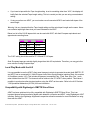
2.0B Avoiding Ground Loops
In today’s studio, where it seems every piece of gear has a computer in it, there are
many opportunities for ground loop problems to occur. These show up as hums,
buzzes, or sometimes radio reception and can occur if a piece of equipment “sees”
two or more different paths to ground, as shown below.
One path goes from device A to ground via the ground terminal of the threeconductor AC power cord, but A also sees a path to ground through the shielded
cable and AC ground of device B. Because ground wires have a small amount of
resistance, small amounts of current can flow through ground and generate a voltage
along the cable shield. This signal may end up getting induced into the hot conductor.
The loop can also act like an antenna into which hum is induced, or can even pick up
radio frequencies. Furthermore, many components in a circuit connect to ground. If
that ground is “dirty” and contains noise, it might get picked up by the circuit. Ground
loops cause the most problems with high-gain circuits, since massive amplification of
even a couple millivolts of noise can give an audible signal.
Most ground loop problems can be solved by plugging all equipment into the same
grounded AC source. However, it is important to make sure that the AC source is not
overloaded and is properly rated to handle the gear plugged into it.
For really tough cases, you may need to break the connection that causes the loop
condition. One way to do this is to simply break the shield of the shielded audio
cable at some point, usually by disconnecting it from ground at one jack. (The other
end should remain connected so that the shielding properties are retained, even if
there is no direct path for ground.)
Please note that not all hums and buzzes are caused by ground loops; your cables
must be of very high quality, particularly with -10 dBV setups. Refer to section 2.1 for
more information.
2.1
AUDIO CABLE TIPS
The connections between ADAT and your studio are your music’s lifeline, so use
only high quality cables. These should be low-capacitance shielded cables with a
stranded (not solid) internal conductor and low-resistance shield. Although quality
cables cost more, they do make a difference. Route cables to ADAT correctly by
observing the following precautions.
•
Do not bundle audio cables with AC power cords.
•
Avoid running audio cables near sources of electromagnetic interference.
•
Do not place cables where they can be stepped on. Although stepping on a cable
may not cause immediate damage, it can compress the insulation between the
center conductor and shield (thus degrading performance) or reduce the cable’s
reliability.
•
Avoid twisting the cable or having it make sharp turns.
2.2
•
Never unplug a cable by pulling on the wire itself. Always unplug by firmly
grasping the body of the plug and pulling directly outward. If you experience
difficulty in removing the plug, sometimes a slight rotating motion while unplugging
will solve the problem.
•
Keep the cable contacts clean at all time. Oxidation may lead to intermittent
contacts, degraded sound quality, or even distortion. DO NOT USE AN
ABRASIVE TO CLEAN A DIRTY PLUG. This may remove some of the plug’s
conductive plating. Instead, spray contact cleaner on a clean, lint-free cloth and
vigorously rub the plug until the oxidation is gone.
AUDIO—UNBALANCED INPUTS
2.2A Input Jack Characteristics
ADAT includes eight unbalanced, 1/4” phone jack inputs. These are compatible with
the low-impedance, unbalanced, -10 dBV outputs typically emanating from equipment
such as mixers, synthesizers, samplers, direct boxes, etc. Guitars, microphones,
and other low-level/high-impedance output devices require a preamp or should be
routed through a mixer with mic preamps.
The unbalanced input jack wiring convention is:
•
Tip: signal hot
•
Sleeve: shield and ground
2.2B Typical Input Jack Hookups
The input jacks are typically hooked up in one of three ways:
•
To the console’s direct tape outs (these patch a single channel directly to
tape, bypassing most mixer circuitry). This is preferred when the signals going
to tape require none of the mixer’s features (effects, grouping, routing, etc.).
•
To eight mixer bus outputs. You can use the mixer for grouping, premixing,
effects, etc. This puts more circuitry between the input signals and ADAT,
although since most routing can be done at the mixer, you’ll seldom need to do
any repatching.
•
To a combination of direct outputs and bus outputs. Some situations require
a combination of the two approaches. Example: Consider a live gig you want to
record with two vocal mics, four mics on drums, two direct feeds from guitar and
bass amps, and one direct feed from keyboards. The vocals, bass, guitar, and
keyboards could be taken direct and go to five ADAT tracks. The four drum mics
can be mixed to stereo within your mixer sent to the submix outs, then go to two
ADAT tracks. The remaining ADAT track could be used to record audience
sounds or capture one of the instruments in stereo, if applicable.
2.2C Special Unbalanced Input Jack Wiring
ADAT has a switched-jack wiring scheme that makes it possible to use an ADAT
even with a 2-output mixer.
Jacks 1, 3, 5, and 7 are normalled together, as are jacks 2, 4, 6, and 8. Anything
plugged into input 1 also feeds inputs 3, 5, and 7; anything plugged into input 2 feeds
inputs 4, 6, and 8. However,
plugging into any input interrupts the normalization, letting you use that jack by itself.
Example: With plugs inserted into inputs 1 and 5, the signal at input 1 also appears at
inputs 3 and 7. Input 5’s signal appears only at input 5.
This means that the buss outputs of a two buss board could be plugged into inputs 1
and 2 and routed to track pairs 1-2, 3-4, and 5-6 on multiple passes without
repatching cables by engaging the record enable switches for the desired tracks.
(On the first pass, enable record on tracks 1-2, on the second, 3-4, and so on). The
same applies for a four buss board. The first pass could be routed to tracks 1-4, and
the second to tracks 5-8. Using this technique will allow you to selectively route
signal to ADAT tracks using only ADAT's record enable buttons and your mixing
board's buss assigns.
Note that the unbalanced inputs and balanced inputs can be used simultaneously, but
the jack normalling feature is available only on the unbalanced 1/4" phone jack
inputs.
2.3
AUDIO—UNBALANCED OUTPUTS
The -10 dBV outputs use mono 1/4” phone jacks, and carry signals at a nominal -10
dBV level. These usually drive mixer
channel inputs or tape returns. They can be used at the same time as the balanced
outputs.
2.4
AUDIO—BALANCED INPUTS AND OUTPUTS
For convenience, ADAT includes +4 dBu balanced line inputs and outputs on a rearpanel multipin connector. Remember, the unbalanced and balanced inputs/outputs
are available simultaneously. (For diagram see Section 9.3 - Appendix 4)
2.5
DIGITAL I/O
The digital I/O connector follows a proprietary Alesis format that carries all eight
outputs on a single fiber optic cable . In conjunction with the BRC Remote Control the
Digital I/O is a very powerful feature that allows you to perform complex assembly
editing, fly parts from one ADAT to another, etc. all in the digital domain and without
any signal degradation. Also, the optional AI-1 ADAT AES/EBU Interface can use
this signal to provide AES/EBU and S/PDIF standard digital inputs and outputs. Refer
to the AI-1 manual for more information.
Since the fiber optic connector carries the digital information for all 8 tracks of the
ADAT it is also useful for backing up all tracks in one pass (section 6.1). You may
increase the pitch control to maximum (section 4.0) to speed up this process
somewhat.
2.6
SYNC
To sync together two or more ADATs, connect the Sync Out from the master to the
next ADAT’s Sync In. Its Sync Out can in turn feed a third ADAT’s Sync In, etc. This
requires a shielded dual male, 9-pin D connector cable available at your Alesis
dealer. For more information on syncing ADATs together, see Chapter 5.
2.7
METER BRIDGE
To connect ADAT to the Alesis RMB Remote Meter Bridge, run a dual male, 9-pin D
connector cable from the ADAT Meter Bridge out connector to the RMB input
connector.
2.8
FOOTSWITCHES
Any momentary single-pole/single-throw footswitch, normally open or normally
closed, will work for the two footswitch functions. These should be plugged in prior to
power-up so that ADAT can configure itself for the type of footswitch being used.
CHAPTER 3: GETTING READY TO RECORD
3.0
POWER-UP AND TAPE INSERTION
After all connections are made, turn on power. ADAT first checks whether a tape has
been inserted.
•
If a formatted tape is present, the counter shows the elapsed time since the
beginning of the tape.
•
If an unformatted tape is present, the counter will show “noFO,” and the FORMAT
LED will flash to indicate that the tape needs formatting. At this point you should
format the tape (see next section).
•
If there is no tape, the counter shows "----" to indicate no tape is present.
Insert the end with the hinged door first, label side up, until you
encounter a slight bit of resistance. Push gently on the center of the cassette until
ADAT draws the tape inward. Once ADAT has started to pull in the tape, do not keep
pushing the tape in.
Note: to record on a S-VHS cassette, the write protect tab (located on the spine of
the cassette) must be intact. If you try to record on a tape that has had the write
protect tab broken off, the display will read "Prot" and the ADAT will not record on the
tape. This allows you to prevent accidental erasure of valuable recordings. To
record on a tape that has had the tab broken off, simply use a piece of scotch tape,
label, etc. in place of the write protect tab to completely cover the hole in the
cassette's spine.
3.1
FORMATTING A TAPE
Just as formatting a floppy disk lets a computer know where to place data, formatting
an ADAT tape time-stamps the tape to single-sample accuracy so that audio is
referenced to an accurate time base. This allows for simplified synchronization,
accurate tape counter readings, and intelligent autolocation with the BRC Remote
Control.
When formatting begins, ADAT writes some setup data during the first two minutes
and 15 seconds of tape, then at time -00:05, writes the time in minutes and seconds
onto a special sync track. This does not use up any of the eight audio tracks. Please
note: The display shows timings with a period separating the hours and minutes
(00.00), but this manual shows a colon instead of a period for clarity (00:00).
3.1A To Format A New Tape, or Reformat/Erase
an Old Tape
•
It is a good practice to "exercise" the tape before
formatting it by fast forwarding it to the end, then rewinding it back to the lead. This evens out
the tape pack and relieves any stresses and strains that may have occurred during tape
manufacture and storage.
1
Press the Format button (if the tape was unformatted, the FORMAT LED will
have been flashing prior to pressing it). Once pressed, the FORMAT LED glows
steadily to indicate that formatting will begin if ADAT enters record mode. Also, all
eight track RECORD LEDs will flash to indicate all eight tracks will be recorded.
Pressing the eight record buttons has no effect while the FORMAT LED is lit
steadily.
2
Press Record and while holding it down, press Play. ADAT briefly enters play
mode to achieve proper speed and check if the tape is formatted.
3
If the tape is at the very beginning, ADAT performs a complete format by
recording 15 seconds of leader (display shows “LEAd”), two minutes of data
(display shows “dAtA”), then time code starting at -00:05 and continuing to the
end of the tape.
If an unformatted tape is not at the very beginning, then format is disabled and no
recording will take place. Be sure to rewind to the beginning of the tape before
formatting it for the first time.
3.1B To Extend A Format
Sometimes, you may not have time to format an entire 40-minute tape before using it,
although this is the best practice. This results in a tape that is only partially
formatted. For example, you may record only one song which ends four minutes into
the ADAT tape. If you want to use the rest of the tape, you must perform a format
extension. Play or fast forward the tape to just before the end of the previously
formatted section, and enter Format mode. Everything on the tape will be erased
from that point on. ADAT reads the sample-accurate time code of the original format
and begins formatting starting from that time onward, thus ensuring continuous timestamping when a tape plays from beginning to end.
For this reason, if you plan to extend a format, don't press Stop immediately at the
end of the song when formatting. Leave a "buffer" of 15 seconds so you won't erase
the last note of the previous song when you extend the format for the next one.
Note:
Format extension is not possible from the LEAD or DATA sections of the tape. If the
tape is formatted but is in the leader or data sections of the tape (i.e., prior to time
00:00), entering format mode will automatically rewind the tape to the beginning and
start reformatting. While rewinding, the display shows “-FO-” and the rewind LED
flashes. This indication is telling you that ADAT must "FORMAT OVER" from the
LEAD or beginning portion of the tape.
3.1C Additional Format Considerations
•
Audio can be recorded while formatting, just in case you have a hot musical idea
but no formatted tapes. Simply press record enable for the tracks to be recorded
before pressing the Format button. Tracks not enabled prior to pressing Format
will be recorded with silence, and cannot be enabled once formatting begins.
•
It is a good practice to "exercise" the tape before formatting it by fast forwarding it
to the end, then rewinding it back to the lead. This evens out the tape pack and
relieves any stresses and strains that may have occurred during tape
manufacture and storage.
•
Blank tapes must be rewound to the very beginning in order
to be formatted.
•
Caution: Do not re-format over a previously formatted tape, then stop reformatting. When the tape transitions from the newly-formatted part to the
previously formatted part, there will be timing discontinuities and the audio will do
unpleasant things. Also, during that transition the tape will be non-functional and
you will not be able to record anything over it. When in doubt, either re-format the
tape all the way to the end, or back up a bit and do a format extension (see
previous section and next section) when you need to re-format over the transition
zone.
•
For safety, label your tape. You don’t want your ADAT tape
confused with a standard video tape.
•
The only way to stop formatting is to press Stop—punching
out is not sufficient.
•
Tapes can be bulk-erased with a bulk tape eraser.
•
In a multiple-ADAT setup where one is the master and other
ADATs are slaves, there are several other considerations. See Chapter 5.
3.1D Record a "Benchmark" Tape
We recommend that you format and record a new tape with any signal, such as a
test tone, in a single pass with no overdubs during the first week of operation. Store
this tape in a safe, dry location and don't use it for any other purpose. Such a
"benchmark" tape is useful to determine if the error correction rate is increasing over
time because the heads need to be cleaned, or if a tape is defective. See Section
9.2.
3.2
TRACK RECORD/MONITOR CONTROLS
These controls determine which tracks will be recorded on in record mode, and
whether tracks will monitor the input or taped signal.
3.2A Record Enable Buttons
To record enable a track, press the track’s associated record enable button. The
track RECORD LED will flash to indicate the track is record-ready. Recording will
begin, as indicated by the RECORD LED being lit steadily, if the transport is put into
record mode (section 3.4F). To turn off record enable, press the track’s associated
record enable button again. Its RECORD LED will turn off.
Record enable buttons cannot be turned on or off while you’re in record.
3.2B Auto Input Monitor
This switch toggles between two tape/input monitoring options. It determines what
signal will appear at the ADAT's Output jacks when a track is record-enabled (red
LED flashing). When a track monitors the input signal, its associated INPUT LED is
lit.
•
With Auto Input OFF (AUTO INPUT LED off), all record-enabled tracks monitor
the input signal and all other tracks monitor the taped signal.
•
With Auto Input ON (AUTO INPUT LED lit), there are two selectable modes to
choose from:
Mode 1: This is the default mode and allows input monitoring of record enabled
tracks in Record, Stop, Rewind, or Fast Forward; but not in Play. In Mode 1 you
are always monitoring the input of record enabled tracks, except in Play. This
allows the engineer to hear musicians even when the deck is stopped, without
changing any console settings.
Mode 2: This mode monitors the input of record enabled tracks ONLY in Record
mode. In Mode 2 all tracks monitor the taped signal until ADAT enters Record, at
which point the record-enabled tracks monitor the input signal. This means the
engineer will not hear the musicians "live" through the deck unless it is actually in
record mode.
To select Mode 2, press and hold SET LOCATE and press AUTO INPUT
MONITOR. The counter will briefly display 'tAPE', indicating Mode 2. To switch
back to Mode 1, press and hold SET LOCATE and press AUTO INPUT
MONITOR. The counter will briefly display 'In', indicating Mode 1.
The reason for having these two options is to accommodate different stages of the
recording process. Auto Input Off is the “normal” option and is what you would use
when first recording tracks. As you record, you want to monitor the input signal being
recorded, as well as any signals from tracks you’ve already recorded on tape.
However, when doing punch-ins and overdubs, Auto Input will probably be On so that
you can hear what was recorded on tape for a given track right up to the point you
want to punch in. As soon as ADAT punches into Record mode, the taped signal
drops out as the monitor switches over to the input signal so you can hear what’s
being recorded to tape. After punch out, the track reverts to monitoring what’s on
tape.
3.2C All Input Monitor
With this function on (ALL INPUT MONITOR LED lit), the auto input monitor setting is
overridden so that all tracks monitor their input signals regardless of their record
enable status. All eight track INPUT LEDs will be lit.
With All Input Monitor off, the Auto Input Monitor setting determines track monitoring.
3.2D Digital Input
This switch determines whether ADAT will record from its analog inputs (balanced or
unbalanced) or digital input. To record from the digital input, press the switch; its LED
will light. All eight channels will be received via the fiber optic connection (section 6.1)
and the analog inputs will be ignored.
DIGITAL IN can be turned on or off only when the ADAT is in STOP mode. When
recording while DIGITAL IN is on, the ADAT's speed is slaved to the clock of the
incoming digital signal. The PITCH controls will have no effect when recording from the
digital inputs, although they will remain lit. Do not turn on DIGITAL IN if nothing is
connected to the digital input, since the ADAT will "hunt" for a clock that isn't there,
causing long sync times. (For the one exception to this rule, see Section 6.1A.)
3.3
SETTING LEVELS
Unlike analog tape recorders, whose meters indicate “0 VU” at the ideal nominal
recording level, with 10 to 15dB headroom above the point, 0dB on ADAT represents
the maximum possible signal level. Signals above 0dB will be clipped and lead to
digital distortion—an ugly, splattering sort of sound.
As on most digital recorders, O dB on the ADAT meter is referenced to full scale, the
maximum signal that can be recorded in 16 bits. Reference-level signals plugged into
ADAT are recorded 15 dB below full scale. For example, if your mixer has +4 dBu
balanced outputs that are connected to ADAT's +4 dBu multipin ELCO connector (or it
has -10 dBV unbalanced outputs connected to ADAT's 1/4" phone jacks), when your
mixer's meter reads 0 VU, the ADAT meter will read -15 dB. Therefore, you can run
your mixer levels "into the red" over 0 VU and still not distort the ADAT until the
mixer's meter reads "+15". Just remember that no matter what, if ADAT's meters
indicate 0 dB (highest red LED lit), distortion is on the verge of occurring.
Theoretically, the lowest noise and distortion in an ADAT recording occurs just as the
highest input peaks barely reach 0 dB full scale. Unlike analog recorders (which get
more and more distorted with higher levels), an ADAT tape that is recorded "in the
yellow" will sound great. However, in setting levels you must strike a balance
between what you gain by recording at high levels, and what you might lose if the
incoming signal hits the "digital brick wall" above 0 dB and distorts on a peak. This is
especially true in live recording, where peak levels are hard to predict. You must also
be careful when setting levels to make sure that the mixer isn't distorting. In critical
situations, consider limiting the input signal using the Alesis 3630 Compressor/Limiter
to ensure against overload and get a maximum level without distortion.
The ADAT meters are the instantaneous peak reading type: any voltage, no matter
how short, will be registered, because the peak level is all that matters to ADAT.
Other meters (as on most mixing consoles) may have different ballistic characteristics
or show average level instead of peak. It is normal for them not to match the ADAT
meters exactly. The RMB Remote Meter Bridge provides peak metering for four
ADATs in a rack-mountable package, and can be mounted above the console or the
BRC Master Remote Control. The RMB also features peak-hold features that make it
easier to avoid distortion.
3.4
TRANSPORT CONTROL OPERATION
The transport controls resemble those of a conventional tape recorder, although there
are several extra features.
3.4A Eject
Press to eject the tape from ADAT. If the tape is moving, it will stop before ejecting.
Note: This control does not operate while recording or formatting to avoid interrupting
these processes.
3.4B Rewind
Press to rewind the tape, as confirmed by the REW LED. When fully rewound, the
REW LED turns off and the STOP LED lights.
•
Pressing Rewind while recording punches out before rewinding.
•
Engaged tapes rewind at about ten times normal speed. Disengaged tapes
rewind at about twenty times normal speed.
•
For the fastest rewind, press the Stop button twice, or until the Stop LED flashes,
before pressing REW.
•
Pressing Rewind while holding the Play button initiates “review” mode. The tape
rewinds at about three times normal speed, and you can hear chunks of
attenuated audio so you know where you are in the tape. The PLAY LED will be
lit, and the REW LED will flash. Releasing the Rewind button returns to normal
Play mode.
3.4C Fast Forward
Press to fast forward the tape, as confirmed by the FFW LED. Upon reaching the
end, the FFW LED turns off and the STOP LED lights.
•
•
Pressing Fast Forward while recording punches out before fast forwarding.
Engaged tapes fast forward at about ten times normal speed. Disengaged tapes
fast forward much faster.
•
For the fastest rewind, press the Stop button twice, or until the Stop LED flashes,
before pressing REW.
•
Pressing Fast Forward while holding the Play button initiates “cue” mode. The
tape fast forwards at about three times normal speed, and you can hear chunks
of attenuated audio so you know where you are in the tape. The PLAY LED will
be lit, and the FFW LED will flash. Releasing the Fast Forward button returns to
normal Play mode.
3.4D Stop
This button performs three functions.
•
Stop the transport. Push to stop any function involving tape motion. A lit STOP
LED indicates that the tape is not moving and is engaged. A flashing STOP LED
indicates that the tape is not moving and is disengaged.
•
Disengage/engage the tape. While the STOP LED is lit, press STOP again to
disengage the tape (STOP LED flashes). While the STOP LED is flashing, press
STOP again to engage the tape (STOP LED is lit). Entering Play or Record will also
engage the tape.
•
Punch out. While recording, if you press and hold PLAY then press STOP, the
tape continues to play but any tracks that were recording exit record mode.
3.4E Play
Press to play the tape (PLAY LED is lit). The Play button by itself has no effect while
playing, recording, or formatting.
While locating, pressing Play will cause ADAT to start playing after finding the
location (PLAY LED will flash); pressing Play twice stops the locate procedure and
ADAT immediately goes into play mode.
Pressing Play in any mode other than locating causes the transport to enter play
mode, and the PLAY LED lights.
Note:
What happens when you press Play after inserting a tape into ADAT depends on
whether the tape being played is formatted or not:
•
Formatted. The tape plays normally and the counter shows the elapsed time
since the beginning of the tape.
•
Unformatted tape. ADAT will detect the lack of a format and flash the Format
LED while displaying "noFO".
•
Tape transitions from a formatted to unformatted section while playing
back. ADAT will detect the lack of a format and flash the Format LED while
displaying "noFO".
•
Tape transitions from a formatted to unformatted section while recording.
ADAT will detect the lack of a format and stop.
3.4F Record/Punch In or Out
Use Record to enter or exit record mode, and to format a tape. To start recording:
•
Press and hold Play, then press Record, to cause any recordenabled track to enter record mode. This is recommended for punching “on the
fly.”
•
Press and hold Record, then press Play, to cause any recordenabled track to enter record mode. This is recommended for initiating recording
when the tape is stopped, or for punching “on the fly.”
To punch out and stop the transport, simply press Stop. There are three ways to exit
record mode (punch out) yet have the transport continue to play; use whichever one
is most natural to you.
•
Press and hold Play, then press Record.
•
Press and hold Record, then press Play.
•
Press and hold Play, then press Stop.
Caution:
If the FORMAT LED is lit, entering record will format the tape (see sections 3.1 and
5.2). This will ERASE any audio previously recorded.
3.5
FOOTSWITCH-CONTROLLED PUNCHING
The rear panel Punch In/Out jack accepts any momentary, single pole/single throw
footswitch. During power-up, ADAT checks the footswitch to determine whether it is
a normally open or normally closed type, and calibrates itself accordingly. If you use
a footswitch and its operation seems “reversed,” make sure it is firmly plugged into
the jack, then turn off ADAT, wait a few seconds, and turn ADAT on again. It will
recalibrate itself to work with the footswitch.
Here’s how the Punch In/Out footswitch works.
•
If a track (or tracks) is record-enabled, and the tape is playing, pressing the
punch footswitch puts the track(s) into record mode at the instant you punch.
This is equivalent to pressing Play and Record to enter Record mode.
•
If ADAT is already in record mode, pressing the footswitch
punches out of record (the tracks will remain record-enabled should you need to
punch again later on) and the tape will continue to play.
CHAPTER 4: PITCH, AUTOLOCATION, AND
REMOTE CONTROLS
4.0
PITCH CONTROLS
ADAT has the capability of changing speed and pitch. It displays speed in cents, or
1/100th of a semitone. For example, if a song is recorded at the standard pitch in the
key of C, and played back with the pitch up 100 cents, it will be in the key of C#.
Press Pitch Up to gradually move the pitch higher (+100 cents maximum), and Pitch
Down to gradually move the pitch lower (-300 cents maximum). After a brief delay
during which the display shows the current pitch, the pitch changes and the display
shows the amount of pitch change in cents. One of the PITCH LEDs will remain on to
remind you that the pitch has been changed from standard pitch. Keep in mind that
the counter will not elapse in real time when the pitch is set to a value other than zero.
To return to standard pitch, press both the Pitch Up and Pitch Down buttons
simultaneously. The PITCH LEDs will be off when ADAT is at standard pitch.
When you change the pitch on ADAT, the sampling rate also changes. At standard
pitch, the sampling rate is 48 kHz. At -147 cents, the display will read "44.1" to show
that this speed corresponds to the consumer sampling rate of 44.1 kHz. At -300
cents, the sampling rate is 40.4 kHz; at +100 cents, the sampling rate is 50.8 kHz.
Note that the internal pitch controls are overridden when the ADAT is being controlled
by an external synchronizer such as the BRC Master Remote Control or the AI-2
Audio/Video Synchronization Interface. Also, when the DIGITAL IN LED is lit, the
ADAT's speed and pitch are controlled by the sample rate of the incoming digital
signal.
4.1
AUTOLOCATION CONTROLS
ADAT can automate the process of finding specific points on the tape. This is called
autolocation.
ADAT autolocation works by specifying three points on the tape (0, 1, and 2) to which
you want to autolocate, as referenced to the time code embedded in the tape’s
format. You can tell ADAT to find one of these three points at any time. ADAT will
either rewind or fast forward, as indicated by the REW or FFW LED flashing, to find
the specified point. If you initiate autolocation while ADAT is in record mode, it will
punch out before autolocating.
ADAT will stop after autolocating unless Auto Play (section 4.1D) is enabled or the
Play button is pressed during the autolocate process, in which case ADAT will start
playing after completing autolocation.
4.1A Setting Locations
To set a location, press and hold the Set Locate button. While
holding it, press one of the Locate number buttons. The following occurs:
•
Set-Locate 0 This resets the tape counter to 00:00, even if the absolute tape
time location is different. (Regardless of where the 00:00 point is set, the counter
will indicate “LEAd” during the first 15 seconds of setup data and “dAtA” during
the next two minutes of set up data at the beginning of the tape). Pressing Set
Locate and Locate 0 while the counter shows 00:00 sets the display to read the
absolute tape time location.
Ejecting a tape with a user set 00:00 will reset the counter to display absolute
tape time of the next tape inserted. Locations 1 and 2, if set, will always reference
the same point on the tape regardless of whether the counter is reset to 00:00. In
other words, once Locations 1 and 2 are set, they reference the embedded time
value in the tape format rather than the counter setting.
•
Set-Locate 1 Holding Set Locate then pressing Locate 1 stores the tape location
into a memory buffer for later recall.
•
Set-Locate 2 Holding Set Locate then pressing Locate 2 stores the tape location
into a second memory buffer for later recall.
4.1B Autolocating to One of the Three Location Points
•
Locate 0 Press this button to have ADAT autolocate to the 00:00 location.
Remember, this can be anywhere on the tape since setting the Locate 0 point
resets the tape counter to 00:00.
•
Locate 1 Press this button to have ADAT autolocate to the location currently
stored in the Set-Locate 1 memory buffer.
•
Locate 2 Press this button to have ADAT autolocate to the location currently
stored in the Set-Locate 2 memory buffer.
4.1C Shuttling Between Locate 1 and 2
Enabling the Auto 2>1 button causes ADAT to automatically return to the Locate 1
point after reaching the Locate 2 point. This works during playback or record. Here
are some fine points regarding this function:
•
If Auto 2>1 is enabled while ADAT is playing and past the Locate 2 point,
autolocation will not occur since ADAT has to pass through the Locate 2 point
before it will look for Locate 1.
•
If Locate 2 is reached while ADAT is in record mode, ADAT will punch out before
autolocating to the Locate 1 point.
•
If Locate 2 is located before Locate 1 on the tape and Auto 2>1 is enabled, the
Auto 2>1 LED will flash to indicate that Locate 1 must precede Locate 2.
•
If Auto 2>1 is on and you set Locate 2 while the tape is playing, the transport will
store the new Locate 2 point and return immediately to the Locate 1 point.
•
If Auto 2>1 is turned off while ADAT is returning to the Locate 1 point, the
transport will still find the Locate 1 point.
4.1D The Auto Play Function
Enabling Auto Play (its LED will be lit) causes ADAT to automatically enter Play
mode whenever any autolocation function is complete, although this can be
overridden by the transport controls. This button can be pressed at any time.
Note:
A 'one time" auto play function can be initiated by pressing PLAY once after initiating
a locate search and before the locate point is reached. The PLAY LED will flash until
the locate point is reached, then enter play mode. Pressing PLAY twice will cancel
the locate search and initiate play mode.
4.1E Record, Then Audition Your Part
If you locate to Locate 1, enable Auto 2>1 and Auto Play, then start recording,
recording will occur and continue until ADAT passes through the Locate 2 point.
ADAT will then punch out, rewind back to Locate 1, and play back what you just
recorded so you can audition your part. Upon reaching Locate 2, ADAT will again
return to Locate 1. If you want to redo the part, press Stop, go into record mode, and
start the process all over again or use the punch-in footswitch after it has located
back to Locate 1.
4.2
FOOTSWITCH CONTROLLED AUTOLOCATION
The rear panel Locate/Play/LRC jack can be used with any momentary, singlepole/single-throw footswitch. During power-up, ADAT checks the footswitch to
determine whether it is a normally open or normally closed type, and calibrates itself
accordingly. If you use a footswitch and its operation seems “reversed,” make sure it
is firmly plugged into the jack, then turn ADAT off, wait a few seconds, and turn it on
again. It will recalibrate itself to work with the footswitch.
The Locate/Play footswitch has three functions.
•
If the transport is currently stopped, pressing the Locate/Play footswitch is
equivalent to pressing the Play button.
•
•
If the transport is currently playing or recording, pressing the
Locate/Play footswitch causes the transport to autolocate to the Locate 1 position
and then either Stop or Play, depending on the Auto Play switch setting.
If ADAT is in the process of locating, pressing the Locate/Play footswitch will stop
the transport.
The footswitch can also be used simultaneously with the LRC remote control if you
observe certain precautions. See the next section.
4.3
USING THE LRC REMOTE CONTROL
To use the LRC, plug it into the Locate/Play/LRC jack. It can control a single ADAT
or the master unit in a chain of ADATs. The LRC offers the following functions:
•
Transport functions. Rewind, Fast Forward, Stop, Play, Record.
•
Autolocation functions. Locate 0, Locate 1, Locate 2, Set Locate, Locate 2>1,
and Auto Play.
•
Track functions. Auto Input and All Input.
Note:
If the Locate/Play footswitch is a normally open type, the footswitch and remote
control can be interchanged at any time, or used simultaneously with a Y-cord. If the
Locate/Play footswitch is a normally closed type, ADAT will have to be reset when
switching between the footswitch and remote, and they will not work simultaneously
with a Y-cord. To do this:
1
Unplug the device you don’t want to use (footswitch or remote).
2
Turn off ADAT.
3
Plug in the device you want to use (footswitch or remote).
4
Turn on ADAT.
CHAPTER 5: MULTIPLE
ADAT OPERATION
5.0
MULTIPLE ADAT BASICS
Two ADATs, with one serving as the master recorder and the other serving as the
slave, provide additional possibilities:
•
16 tracks of synchronized digital audio storage.
•
Simplified backup (see Chapter 6).
•
Easy musical collaboration with other ADAT-equipped musicians.
•
Easy creation of safeties and archives of parts. Example: Suppose your rhythm
section is in four tracks of one ADAT. You can then do eight tracks worth of
guitar, vocal, brass, or other overdubs in the other ADAT, and bounce the
“keeper” parts over to empty tracks in the original tape. Once these tracks are
filled up, you can then do a premix to the second ADAT, and continue recording
on empty tracks in the second ADAT.
It is also possible to synchronize up to 16 ADATs for 128 tracks.
One ADAT serves as the master and all the others as slaves. Therefore, operating
procedures are similar to using two ADATs, just that there are more slaves.
Important: In a multi-ADAT system, all ADATs should be of
the same software version for best performance. To check the software version,
hold Set Locate and press Fast Forward on each machine. The software version of
the ADAT will show in its display for a moment. If you must mix software versions
temporarily, the latest software version should be the master machine. Software
upgrades are available through Alesis to make sure all machines are compatible.
Contact Alesis Product Support for assistance.
5.1
SYNCHRONIZING MULTIPLE ADATS
5.1A Hooking Up Multiple ADATs
Synchronization requires a dual male, 9-pin D cable for each pair of ADATs to be
synchronized. This connection can be made while power is on or off, and ADATs do
not need to be turned on in any particular order in a multiple ADAT system.
Use the correct cables: Most problems in multi-ADAT systems are the result of
using the wrong cables. The 9-pin cable must be shielded, and wired pin-to-pin.
Alesis Sync Cables that meet this specification are available from your ADAT dealer.
Use the shortest length practical for your arrangement.
1
Connect one end of the cable to the master ADAT’s Sync Out jack. Push the
connection in firmly, then tighten the screws at each side of the connector.
2
Connect the other end of the cable to the slave ADAT’s Sync In jack and tighten it
as above.
3
If there are additional slaves, connect one end of an Alesis Sync Cable to the first
slave’s Sync Out jack, and the other end to the second slave’s Sync In jack. Its
Sync Out jack then connects to the third slave’s Sync In jack, and so on.
5.1B ADAT ID (Identification) Numbers
After you’ve connected multiple ADATs and turned the machines on (they can be
turned on in any order), the master’s display will show Id 1 (which stands for ID=1).
The second machine will show Id 2, the third Id 3, and so on. This order is
automatically assigned according to how the cables are hooked up.
If a slave does not show an ID number on power-up, then it does not see anything
connected to the Sync In or Out. Check the cables and connections to determine the
source of the problem.
If needed, ADATs will renumber their IDs if more ADATs are connected later.
Example: Suppose you have three ADATS hooked up so that machine 1 is the
master, and machines 2 and 3 are the slaves. If you turn on machines 2 and 3,
machine 1 will not be active so machine 2 will decide it’s the master (Id 1) and
machine 3 will be the slave (Id 2). If you turn on machine 1, the ADATs will renumber
themselves so that machine 1 becomes the master (Id 1) and machines 2 and 3
become the slaves (Id 2 and Id 3 respectively).
Note that in the above hookup, if machines 1 and 3 are turned on but machine 2 is
turned off, machine 3 will not slave to 1 because 2 is turned off, so the sync signal
cannot pass from 1 to 3.
5.1C How the Master and Slave Decks Interact
Pressing any of the buttons on the master machine (except for the Record Enable
Buttons, Format, and Digital In) will automatically trigger the same functions on the
slave machine(s) as well. Alesis recommends that you always initiate operations
from the master, including all transport control functions, to minimize confusion. When
you press Play on the master, the slave(s) will locate to the same time code point if
needed, then begin playing as soon as sync is achieved.
When recording or punching in on the slaves, initiate recording on the master but do
not have any master tracks record-enabled (unless, of course, you need to record
tracks on the master). Any tracks that are enabled on the slaves will go into record.
This is why record enable is an independent function for each slave.
There are two cases where you want the slave(s) to act independently. Formatting is
initiated independently on the slave for a number of reasons, as detailed in section
3.1. Digital in can also be set independently for the slave(s) since you may want to
record via the analog ins on some machines and via the digital ins on others.
5.1D Achieving Lock
In a multi-ADAT system, the ADATs will "chase" the master and can only enter
record once they are in perfect sample-lock. Audio will not appear at the outputs of
an ADAT until sample-lock sync is achieved. When an ADAT is in lock, the PLAY
LED will light solid, and the center decimal point in the display will appear. To
achieve the fastest chase-lock performance from a multi-ADAT system, use the
Locate points whenever possible.
5.1E Independent Slave Mode
If the master ADAT is stopped, then each of the slaves will function independently.
For example, you can press Play on one of the slaves (or change the auto input
monitor, etc.) and it will go into play; the other slaves will not respond. However, any
time you press Play on the master or initiate any transport function, it will take over
and control the slaves.
5.2
FORMATTING WITH MULTIPLE ADAT SYSTEMS
Formatting works similarly to formatting on a single ADAT. However, it is necessary
to consider what the slave does when formatting is initiated on the master.
5.2A Master Format Enabled and Performing a Complete, Start-toFinish Format
If the master format is enabled, performing a complete start-to-finish format, and the
slave tape is not formatted:
•
If the slave format function is on, the slave rewinds to the start of the tape and
does a complete format.
•
If the slave format function is off, the slave rewinds to the start of the tape and
plays, but displays “noFO” (no format) while flashing the format LED.
If the master format is enabled, performing a complete start-to-finish format, and the
slave tape is formatted:
•
If the slave format function is off, the slave rewinds to the start of the tape and
plays in sync with the master.
•
If the slave format function is on, the slave rewinds to the start of the tape and
does a complete format.
Note that if any channels are record-enabled, they will start recording at time 00:00.
5.2B Master Format Enabled and Extending the Format
If the master format is enabled, extending the format, and the slave tape is not
formatted:
•
The slave plays, but displays “noFO” (no format) while flashing the format LED.
If the master format is enabled, extending the format, and the slave tape is formatted:
•
If the slave format function is off, the slave autolocates to the same time as the
master and plays or records in sync.
•
If the slave format function is on, the slave autolocates to the same time as the
master, then format extension begins.
Note that to properly extend the format, the master and slaves should be playing in
sync before punching into format record.
5.2C Master Format Disabled
This assumes that the master initiates the record/play function. If no master channels
are in record mode, the master will play, but send record commands to the slaves if
the master tape is rewound to the very beginning, or in the audio portion of the tape
(i.e., past time 00:00).
If the master initiates recording from anywhere in the tape and the slave format
function is off:
•
If the slave tape is unformatted, the slave plays, but displays “noFO” (no format)
while flashing the format LED.
•
If the slave tape is formatted, the slave autolocates to the same time as the
master and plays or records in sync.
To properly punch in, the master and slave should be in sync before punching.
Otherwise, the master will punch in immediately, but the slaves won’t punch in until
sync is achieved.
If the master initiates recording from the audio portion of the tape and the slave format
function is on:
•
If the slave tape is formatted, the slave autolocates to the same time as the
master and then format extension begins.
If the master initiates recording from the start of the tape and the slave format function
is on, start-to-finish formatting begins regardless of whether the slave tape is
formatted or not.
Caution: If the slave tape was previously formatted and is being reformatted or having
its format extended, do not stop formatting at a point where the old format still exists,
or timing discontinuities may result. See section 3.1A for more information.
5.3
AUTO-LOCATION/LOOPING WITH MULTIPLE ADATS
There are several fine points concerning auto-location and auto-looping in multiple
ADAT systems.
•
Once the master ADAT recognizes the slave ADAT(s), it transmits the master
locate points, Auto Play, and Auto 2>1 settings to the slave(s). Any attempt to
store any locate points on the slave machines will be ignored.
•
Enabling or disabling the master Auto Play and/or Auto 2>1 settings will enable or
disable those settings on the slave(s).
•
When the master and slave play in sync, and you initiate a locate command on
the master, the slave will follow the master. You cannot initiate a locate command
on a synced slave in play mode.
•
When the master and slave play in sync, if the master enters play after locating
(Auto Play), the slave will follow the master. If the master Auto Play function is
disabled but enabled on the slave, the slave will ignore the Auto Play command.
•
When the master and slave play in sync, and the master locates to 1 after
reaching Locate 2 (the Auto 2>1 function), the slave will follow the master. If the
master Auto 2>1 function is disabled but enabled on the slave, the slave will
ignore the Auto 2>1 command.
•
If the slave is running independently (i.e., not synched to the master), then it will
use its own Auto Play and Auto 2>1 settings.
•
The pitch can only be controlled from the master.
CHAPTER 6: BACKUP
6.0
BACKUP BASICS
With analog recording, backing up from one multitrack to another loses one
generation, which adds hiss and distortion. With digital recording, backing up
produces an exact copy or “clone” of the original tape being backed up. This makes it
easy to create safety copies of important tapes, or make multiple copies for
distribution.
Because of ADAT's careful transport and format design, a good quality S-VHS tape
handled properly can be capable of over 1,000 play or record passes across the
head drum without any change to the audio. However, all tapes and environments
are not equal, and no tape of any format, analog or digital, video or reel-to-reel, lasts
forever. When tapes begin to wear out or have dropouts, the ADAT will give you
advance notice via the Advanced Information Indicator (see Section 9.4A). Since
one of the advantages of ADAT is its ability to make digital backups, and another is
the relatively low cost of S-VHS tape, you should make backup safety copies of all
tapes whenever you have invested a great deal of work into that tape. If you have
only one ADAT, your dealer or a local studio may offer an ADAT backup service.
6.1
BACKING UP VIA DIGITAL I/O
Alesis recognizes the importance of backup, so ADAT includes a fiber optic digital
connection that carries all eight ADAT tracks.
There are two ways to make digital copies of an entire ADAT tape:
In the normal method, you make an exact "clone" of the original with the copy
synchronized to the ADAT's internal time code numbering. Use this method if you
have a multi-ADAT setup, or if you're using a BRC, AI-2, or other ADAT time codebased product. The original and the copy will be interchangable, with no change in
the time code offset.
It is also possible to make a digital copy using the optical I/O only, without sync
connections. The only thing that will be different between the copy and the original
will be the ADAT time code. Such copies won't play back the same time code at the
same point in the song as the original. Even so, such non-corresponding time code
copies can still be synchronized to the original with sample accuracy by using the
BRC and finding the proper offset.
6.1A Normal Method (Time Code Accurate)
1. The two ADATs should be connected in the normal manner:
•
•
Connect the SYNC OUT of the master to the SYNC IN of
the slave using an Alesis 9-pin sync cable.
Connect the DIGITAL OUT of the slave to the DIGITAL
IN of the master using the fiber optic cable that came with your ADAT.
2. Put the original tape to be copied into the slave ("id 2") ADAT, which will be the
source.
3. Put a blank or preformatted new tape into the master ("id 1") ADAT, which will be
the target. (If the tape is blank, press Record Enable on all tracks of the master,
and then press FORMAT on the master).
4. Set the master ADAT's clock source to internal by holding SET LOCATE and
pressing DIGITAL IN until the display says "Int".
5. Press the DIGITAL IN switch on the master and slave machine. Both DIGITAL
IN LEDs should be lit.
6. Record enable all tracks on the master (target) ADAT. Make sure all tracks on
the slave are in SAFE mode (red LEDs not on or blinking).
7. Press PLAY and RECORD on the master ADAT.
8. Press STOP on the master after backing-up is complete.
The result is a new "clone" of the original master that will synchronize sampleaccurately as if it were the original.
It is also possible to make a "clone" from the master machine to the slave machine,
although this isn't the preferred method if the source tape has shown any signs of
deterioration. Simply connect the DIGITAL OUT of the master to the DIGITAL IN of
the slave, and press the Record Enable switches on the slave machine instead of the
master. Note: Even though the master machine is the source and may not have
anything plugged into its optical digital input, you still need to press Digital In on the
master and set its clock to internal (hold Set Locate and press Digital In so the
display reads "int"). The reason that the master's DIGITAL IN LED must be lit during
backup is so the master "knows" that it is making a digital transfer, and uses the
proper time settings for a digital transfer. This assures sample-accurate timing
precision.
If some of this is hard to remember, an explanation of how Digital In affects
synchronization may help. Consider a situation where you have two ADATs, and
want to back up the slave ADAT’s tape to the master ADAT. So, you connect the
master's Sync Out to the slave's Sync In, connect the slave ADAT’s digital out to the
master ADAT’s digital in. You now have the hookup shown below:
If you press Digital In on the master without setting the master clock to Int, this sets
up a type of “feedback loop” where the master is trying to synchronize to the slave's
digital signal, which is in turn trying to synchronize to the master, etc. This results in
unstable operation; if the room is quiet you'll hear the servos of the ADATs changing
pitch, and an error message may appear in the display.
To repair this situation, press and hold the Set Locate button, and press Digital In.
The display will read "INT" to indicate that the master will use its internal clock
instead of the clock derived from the optical in. Repeating this process will cause the
display to read "dIG" to indicate that the master will follow the clock derived from its
digital in, which is necessary when the master is receiving digital input from devices
such as the AI-1, QuadraSynth, or QuadraVerb 2.
Note that a slave ADAT (id2 or higher) cannot switch from "dIG" to "int", because a
slave machine always follows the clock from the master ADAT's Sync Out port, not
the clock from the optical input or its internal clock.
6.1B Optical-Only Method
Under this method, the time code locations of the original and the copy will not match.
1. Connect one end of the fiber optic cable into the source ADAT optical output. The
cable is non-polarized, so either end can be inserted into the optical output. (Note
that if the other end of the cable is disconnected and a signal is being sent
through the cable, you will be able to see a red light at the output. This is not a
laser light, so you don’t have to worry about damage to your eyes.)
2. Connect the other end of the fiber optic cable to the target ADAT’s optical input.
3. Insert the tape to be backed up in the source ADAT.
4. Insert a tape in the target ADAT (if it’s not formatted, see section 3.1, or section
5.2 for dual ADAT systems).
5. Select Digital Input on the target ADAT.
6. Record enable all tracks on the target ADAT.
7. Place the target ADAT in Record mode and the source ADAT in Play mode.
8. Press Stop on both machines after backing up is complete.
6.2
BACKING UP VIA ANALOG I/O
If you need to back up a tape and have misplaced the fiber optic cable, don’t panic.
Hook up the eight analog outputs from the source ADAT to the eight analog inputs on
the target ADAT, put the target ADAT into Record mode, and the source ADAT into
Play mode. Although there may be an almost imperceptible loss of quality compared
to a digital transfer, ADAT’s exceptional audio quality is such that you may not even
notice the difference between the two tapes. If the two ADATs are synchronized via
the Sync In/Out 9-pin connection while the copy is made, the timing will still be
sample-accurate.
Similarly, you can use ADAT’s analog outputs to back up the tape to a high-quality
analog deck, such as an eight-track recorder with Dolby SR, or to bounce to eight
tracks of a multitrack analog recorder, digital recorder, or hard disk recording system.
CHAPTER 7: APPLICATIONS
7.0
COMBINED MULTITRACK/ MASTERING DECK
ADAT can serve as a combination 6-track multitrack recorder and 2-track mastering
deck. Record your audio into tracks 1-6, then run them through a mixer into tracks 7
and 8. Tracks 7 and 8 then contain the stereo master recording.
An alternative is to record 5 tracks of audio, and dedicate one track to SMPTE time
code or some other synchronization protocol. MIDI sequencers can be synched to
the tape, and used to drive “virtual” instruments that also feed the mixer.
7.1
ARCHIVING
ADAT is superb for archiving applications.
7.2
•
Archive speeches and broadcasts. ADAT can record over five hours of mono
material by recording 40 minutes on each track.
•
Record over 2-1/2 hours of stereo mixes. Archive them by mixing down to four
sets of stereo pairs.
•
Record libraries of stereo samples into ADAT. Again, this gives over 2-1/2
hours of recording time.
BOUNCING
Although ADAT requires the BRC to do digital bouncing, standard bouncing using the
analog outputs results in virtually imperceptible loss of fidelity. Tracks can be
bounced within ADAT, as well as to other machines.
7.3
LIVE RECORDING
ADAT is excellent for live recording because of its compact size and easy operation.
Eight tracks allow for recording audience sounds, ambience, and individual soloists
as well as a stereo mix off the PA.
7.4
USING ADAT WITH MIDI SEQUENCERS:VIRTUAL TRACKING
There is a trend for hard disk recording and playback to occur within a software MIDI
sequencer environment, however ADAT can offer much of the same flexibility without
the added expense of a new program or hard disk recording system.
Stripe one ADAT track with SMPTE, and sync your sequencer to this SMPTE signal
by whatever means you normally use. As you control ADAT’s tape motion with the
transport controls, the sequencer will automatically follow along, letting you mix digital
recording with any sequencer.
7.6
VIDEO LOCATION RECORDING
With ADAT, there are enough tracks to stripe SMPTE and record seven tracks of
dialog/sound effects on location. ADAT also makes an excellent mixdown deck for
new multichannel formats (such as surround sound) that require more than two
tracks.
7.7
MODULAR RECORDING
Collaborations work particularly well with dual-ADAT systems. You can record your
tracks into one machine, then do a premix into two tracks of the second machine,
which is of course synchronized to the first. Send this tape to your partner, who adds
parts in the other tracks. When the tape comes back, just pop it in the second deck,
and your partner’s parts will be in sync with what you laid down originally.
CHAPTER 8: ADAT ADVANCED FEATURES
8.0
ABOUT THE ADVANCED FEATURES
There are some extra functions built into each ADAT that are not listed in the main
text of your ADAT manual which we will discuss here. While holding the SET
LOCATE switch and pressing certain specified switches, these extra functions can
be accessed.
These extra functions are divided into two sections:
1
Those that you may need one day. Accessing these functions is safe and easy
to do. We have listed these below.
2
Those that are purely for diagnostic and service purposes which should NOT be
accessed. They could put your ADAT out of alignment and even possibly
damage your tapes.
We have not listed those used for diagnostic and service purposes, but it is
conceivable that you may accidentally access them. We strongly caution you not to
experiment with anything other than the functions listed below or you could ruin an
important session, damage tapes irreparably and maybe even necessitate service
work for your ADAT.
8.1
ADVANCED FEATURES
While holding the SET LOCATE switch, pressing the specified switches will do the
following:
8.1A Eject the tape in the Master ADAT of a Mutli
ADAT System
Hold SET LOCATE and press EJECT. This ejects only the tape in the Master
Machine and sends MMC (Midi Machine Control) Stop messages to slave units.
Normally pressing EJECT would stop all connected ADATs and eject all the tapes
simultaneously. Each slave ADAT has its own independent control so their tapes can
be removed at any time.
8.1B Device Id
Hold SET LOCATE and press PLAY. This displays the ID number of each ADAT in
a system and is supplied in case you need to quickly know which ADAT is where in
the chain.
8.1C Auto Input Monitor Option Select
Hold SET LOCATE and press AUTO INPUT. When Auto Input is disabled, record
enabled channels are always monitored from the inputs on the back panel. This
function is only used when Auto Input is enabled (the LED is on) although Auto Input
can be turned on or off regardless of Auto Input status. It toggles between "In"
(monitors input when not playing or recording) and "tAPE" (monitors tape when not
playing/recording, therefore what is at the inputs will not be heard).
8.1D Software Version
Hold SET LOCATE and press FAST FORWARD. This function temporarily displays
the software version of each ADAT.
8.1E Tape Write Protect Status
Hold SET LOCATE and press RECORD CHANNEL 1. This temporarily displays the
record tab status of whatever tape is inserted in the ADAT. "rEcd" means that the
tape is not write protected and you can record."Prot" means the tape has had its
protect tab removed and is write protected.
8.1F Monitor/Audio Path Select
Hold SET LOCATE and press ALL INPUT. Toggles between two options: "In" and
"dAC".
1
"In" - input channel audio comes directly from input, while non-input channel audio
(what is already on tape) goes through the DAC.
2
"dAC" - ALL audio goes through the DACs. The DAC is the Digital to Audio
Converter and is the process where the digital data gets returned to audio. In
normal circumstances you only need to hear the audio at the input stage and the
ADAT will always power up this way. However, it may be critical for you to hear
audio results AFTER the A to D (analog to digital) conversion process which is
why the DAC option is provided.
This is not quite the same as "monitoring off the record head". There are things that
could occur that you may find disturbing. For instance, during punch in/out, you will
hear very obvious clicks. (However, these clicks will not be on tape, it is purely a
byproduct of this type of monitoring.) If you are concerned to make sure things are
"going down on tape" the way you want, nothing beats listening back once you have
done a take.
8.1G Crossfade Select
Hold SET LOCATE and press RECORD. When the ADAT punches in or out, there
is actually a crossfade where the old signal fades out as the new signal fades in. This
process takes 10.67 milliseconds and is therefore not only imperceptible but smooth.
However, there may be circumstances where you want a longer crossfade time and
the ADAT has 4 crossfade times to select from.
"FAd1" = 10.67ms, "FAd2" = 21.33ms, "FAd3" = 32.00ms, "FAd4" = 42.67ms.The
ADAT always powers up with the fastest crossfade time of 10.67 ms (FAd1).
8.1H Digital 48k Master Clock Enable/Disable
Hold SET LOCATE and press DIGITAL INPUT. This applies to the master ADAT in
your system which must always have digital clock source. This function
enables/disables the internal digital 48k master clock. When set to "diG", the ADAT
will use an external digital 48K clock (if one is present). If an external clock is NOT
present, the ADAT will automatically use its own built in 48K clock. When set to "int",
the internal clock will always be used regardless of whether an external digital 48K
clock is present or not.
The ADAT powers up in normal ("diG") mode.
The master ADAT must disable the external clock (i.e. must be set to "int") when it is
receiving digital input from any of its slave units. (See Chapter 6)
8.1I Total Running Time of Drum Motor
Hold SET LOCATE and press STOP. This function temporarily displays the number
of hours the drum motor has been on.
CHAPTER 9: MAINTENANCE/SERVICE
9.0
GENERAL INFORMATION
9.0A Cleaning
Disconnect the AC cord, then use a damp cloth to clean ADAT’s metal and plastic
surfaces.
9.0B Maintenance
Here are some tips for preventive maintenance.
•
Periodically check the AC cord for signs of fraying or damage.
•
Unplug ADAT when not in use for extended periods of time.
•
Place a dust cover over ADAT when it is not in use.
•
Should the ADAT's error correction system be near the limits of its capability, the
rightmost decimal point of the LED display will flash during play. If this should
occur, make a digital back up of the tape. If the problem persists,
contact Alesis.
9.0C Refer All Servicing to Alesis
Alesis has spent a great deal of effort researching recorder reliability. We believe that
ADAT is one of the most reliable recorders that can be made using current
technology, and should provide years of trouble-free use. However, if problems
occur, do not attempt repairs yourself. The full AC line voltage, as well as high
voltage/high current DC voltages, are present at several points within the chassis.
Service on this product should be performed only by qualified technicians. THERE
ARE NO USER-SERVICEABLE PARTS INSIDE.
9.1
ADAT HEAD LIFE
The expected headlife for each ADAT varies according to a number of factors.
Given optimum conditions, tape quality, tape care, and operating environment head
life for the average ADAT will always be better than if your ADAT is abused, placed in
bad environmental conditions and used with badly maintained tapes. Properly cared
for, your heads should last for thousands of hours.
You should not subject your ADAT to environmental extremes, humidity or moisture
of any kind, dust, dirt, extreme temperatures, extreme temperature fluctuations or any
kind of physical abuse (drops, shocks).
Under no circumstances should you remove the top or bottom cover of the ADAT.
You already know that there are NO user serviceable parts inside. However, you
should also be aware that it is extremely easy to damage your heads and other
sensitive parts of your ADAT. Do not open up your ADAT to clean the heads.
What it comes to is this: ADAT is a very sophisticated piece of digital technology. It
is going to be used for your important projects so take the best care of your ADAT
and your ADAT heads possible.
9.2
ADAT HEAD MAINTENANCE
The heads of each ADAT are pre-aligned at Alesis. No user adjustment is
necessary.
Over the course of time, depending on the quality of the tapes used and the
environmental conditions where the ADAT and its tapes are stored, head cleaning
may become necessary. Unlike analog or even video tape recorders, the actual
sound quality of an ADAT recording will not be affected until there is quite a bit of dirt
on the drum and heads. When the Advanced Information Indicator (dot on the bottom
right hand corner of the display) starts appearing frequently, even on brand new
tapes, we recommend that you bring your ADAT to an authorized Alesis Service
Center for cleaning. If the indicator is not appearing and the unit is performing
normally, there is no reason to clean the heads. Periodic or preventative
maintenance is not recommended.
If head cleaning is necessary and you are unable to bring your ADAT to a service
center, you may try using a DRY VHS head cleaning cassette. We recommend:
3M VHSHC Black Watch Head Cleaner Video Cassette
•
Do NOT use any other type of head cleaning cassette. They are abrasive and
will damage or wear out your heads.
•
Do NOT use head cleaning cassettes that require any kind of liquid.
•
Do not use the Black Watch cassette any more often than necessary. Overcleaning the heads wears them down, reducing their life span.
•
Do NOT attempt to clean the heads yourself unless you are a skilled technician
experienced in the maintenance of video cassette recorders. Information for
such technicians is available from Alesis Product Support. ADAT head cleaning
requires different materials and procedures from analog head cleaning, similar to
VCR maintenance. Cleaning the heads with a cotton swab, or rubbing in the
wrong direction, will destroy them. Opening the case of your ADAT will
void the warranty.
Maintenance of the ADAT should be based on the Advanced Information Indicator or
if the unit begins to behave erratically. To determine if these symptoms are caused
by dirty heads, (not a defective or worn tape), keep a "benchmark" tape from the first
weeks of operation set aside in a safe place (See Section 3.1B). If the ADAT
Advanced Information Indicator lights frequently when playing back this tape, it is
likely that head cleaning is needed, particularly if several hundred drum-on hours
have elapsed since the last cleaning. To display the number of hours the heads have
been in use, press SET LOCATE and STOP.
Call Alesis Product Support for more information about head cleaning and authorized
Alesis Service Centers.
9.3
TAPE MAINTENANCE - SAFE TAPE
ADAT tapes are no different than any standard tape: they must be treated with care.
Never expose ADAT tapes to temperature extremes, strong magnetic fields (such as
speakers), high humidity, dust and so on.
You should always practice SAFE TAPE.
•
Don't leave your tapes near speakers, power amps or other potential magnetic
fields such as televisions or electrical devices.
•
Don't subject your tapes to extreme temperatures or wild temperature
fluctuations.
•
Don't expose your tapes to high humidity, moisture or high dust levels.
•
Don't leave your tapes on the dashboard of your car. (In fact, never leave ADAT
tapes in a car EVER. Keep them with you at all times!)
•
Certainly, no matter how tempted you are to open the shutter to see what is
inside, NEVER TOUCH THE TAPE. The magnetic particles on your ADAT tape
need to be preserved in the condition in which they were recorded. The oils from
your fingers WILL damage your tapes as well as get on the heads and damage
them.
•
Never turn off the ADAT power while the tape is threaded. This leaves the tape
bent around the rollers and head. Press STOP until the tape is disengaged
before turning off power.
•
At the end of every session you should rewind the tape all
the way to the leader, stop, eject the tape, remove it from the ADAT and place it in
its protective case. This cuts down on the amount of dust that can enter the
transport and keeps wear on the tape at a minimum.
Practice "safe tape" at all times because you can never retrieve lost data.
If you are archiving your tapes, make sure they are stored in environmentally stable
conditions, i.e. a cool dry place. If you do archive your tapes, you need to check
them once a year. Run each tape through your ADAT from end to end. This will
prevent buildup that can occur when a tape is left simply "sitting".
Of course, for your super sensitive or important material, nothing beats making
multiple digital backups. Every year or so, simply do another digital backup onto a
brand new tape.
9.4
ERROR MESSAGES
Alesis has designed a number of information messages that your ADAT may display
from time to time. In most cases, these messages could indicate a fault as listed
below. They exist for quick diagnosis and problem solving, if problems exist. These
Error Messages do not always mean there is a fault with the ADAT. Sometimes it
could be the video cassette casing, for example.
We have listed these messages below, along with our advice for what to do if and
when they occur.
9.4A ADAT Messages and Explanation:
•
-du- Indicates Environment is too humid (detected by dew sensor). The tape will
not be allowed to be threaded while this condition is present.
SOLUTION: Leave ADAT on and wait. Do not try to heat or cool the ADAT, and
under no circumstances use an air blower (for example, a hair dryer) as you may
cause damage.
•
noFO Indicates the tape is unformatted or, possibly, that the tape has not
threaded from the beginning.
SOLUTION: Format the tape as instructed in Chapter 3. If you know the tape to
have been previously formatted, then either the tape was not fully rewound during
previous use or there has been tape damage caused. Try rewinding the tape. If
that doesn't work, Fast Forward the tape to where you know there is data and
press play. If the display still says "noFO", then it is possible that your tape has
sustained serious damage since last use. See Tape Maintenance (Chapter 9) for
an idea of what could have gone wrong.
All is not lost, however. Play your tape in another ADAT. If it works, then you
need to call Product Support to discuss what to do next. If your tape does NOT
work in multiple machines, then be very glad that you made a backup of your
valuable data. (You DID do a backup didn't you?)
•
Prot Indicates that the tape you are trying to record on is write protected.
SOLUTION: Remove the tape and place some adhesive tape over the write
protect socket in the back corner. Make sure the adhesive tape is firm and also
firmly applied. (You do not need adhesive tape moving about inside your ADAT!)
•
FULL is displayed when a slave ADAT is slow to sync to the master ADAT, and
its serial buffer becomes full of data. Make sure the software versions of all
ADATs are the same by pressing SET LOCATE and FAST FORWARD. Check
the sync cable; it should be of the proper type, shielded, and connected firmly. It
may also be caused by a damaged or defective tape. If this problem persists
after performing the steps below, the machine may need service.
The Advanced Information Indicator is a dot that is displayed in the bottom right
hand corner of the ADAT display. This light, looking like a "period" at the end of the
current tape time, indicates that the error correction circuitry of the ADAT is
operating. There is nothing to worry about if this light occasionally flickers. However,
if it is flashing frequently or stays lit, something is beginning to interfere with the
playback of digital information from the tape. Insert a different tape (such as the
"benchmark" tape referred to in section 3.1B) into the transport. If the Advanced
Information Indicator does NOT flash with this other tape, it indicates that the tape
itself is at fault. You should make a backup copy of the tape as soon as possible
following the procedures in Chapter 6, and work with the backup copy instead of the
original.
If the Advanced Information Indicator flashes frequently with all tapes, try entering
Cue/Review mode by holding PLAY and FAST FORWARD for 20 seconds of tape
travel, then holding PLAY and REWIND for another 20 seconds. This may remove
any particles adhering to the heads. If the indicator still flashes, see section 9.2,
"ADAT Head Maintenance".
If none of these steps work, back your tape up immediately and call Product Support.
9.4B Errors 1 to 9
Errors 1 to 9 are a little more complex. (They are displayed Er 1, Er 2 etc.) Note that
these are error messages that appear in the ADAT display, not in the BRC's display.
Many error messages are the result of temporary problems and you should only take
action if they recur several times. The important thing to know is that the ADAT may
not necessarily be at fault. It may be a particular tape you are using, for example. The
error codes, to be understood fully, must be combined with other technical
information and tests. However, here's a list of their meanings:
Er 0 has to do with the switches that detect the loading and unloading of the tape.
Make sure you weren't too aggressive while inserting a cassette.
Er 1 through Er 3 involve tape threading. If it only happens once, it was a temporary
problem with a piece of dust on the switch. Sometimes, it can be a result of a
tape that's binding; eject the tape and check operation, threading and unthreading
with a blank or unrecorded tape. If these errors recur frequently, or will not go
away, there is a problem with the transport involving the sliding of the loading
arms, capstan motor or pinch roller adjustment, or the switches that detect how
the tape is threaded.
Er 4 means the drum isn't spinning when threading a tape.
Er 5 is that the head drum speed is too slow or too fast relative to tape speed. Most
often it occurs when the ADAT is a slave (or in DIGITAL IN mode) and the clock
that is being received is out of range or not being received well. Check the sync
cable; it should be shielded and routed away from interference sources. If it's in
DIGITAL IN mode, make sure the optical cables are OK and that the ultimate
source of the digital clock is in range. If something in the tape path is too tight, or
there are foreign materials blocking the path, it may cause this problem. If the
error occurs in a stand-alone unit with a known good tape, the machine should be
checked by a technician.
Er 6 occurs when an external unit (such as the BRC) has commanded the ADAT to
read the setup from the data section of the tape, but the data couldn't be read
correctly.
Er 7 means that the error correction during playback exceeded a certain threshold.
In almost every situation, Er 7 is preceded by the Advanced Information Indicator
(see previous page). If the errors are not caused by a bad tape, the heads may
need to be cleaned. See Section 9.2.
Er 8 means that the ADAT lost sync during recording, and therefore fell out of
RECORD mode. This error is most likely to appear when the ADAT is under
BRC or AI-2 control, but the incoming timecode it was trying to synchronize to
has too much jitter or dropout. It may also occur if the ADAT was not able to read
timing information from the tape. It is normal to see Er 8 if the tape has reached
the end. Check the Sync cable (if it is a multi-ADAT system); try another known
good, shielded sync cable. Look at the tape itself and examine it for damage.
Finally, the linear head may need to be cleaned, or other service or adjustments
may be necessary.
Er 9 indicates that the take-up reel didn't move after PLAY or RECORD was
engaged. This can spool tape out of the cassette, so the ADAT stops the tape
immediately. It's possible that the take up reel of the tape is jammed; try a blank
or unimportant tape to see if the error recurs. The idler wheel that turns the takeup reel may need cleaning or replacement.
General note: If these errors occur only with a certain tape, or display once in a
while, it's probably not cause for concern. Errors 1-3 and 9 can indicate
conditions that may damage a tape; the other errors won't damage the tape or the
machine.
9.4C Steps To Take Before Calling For Help
If an error message is displayed or if an ADAT starts behaving strangely, then please
follow the suggested steps below:
1
Stop the tape playing (or recording). Does the error go away?
2
Rewind the tape a minute or two. Press play. Does the error recur?
3
4
Eject the tape. Place it back in the ADAT and press play. Does the error recur?
Turn down the volume of any mixer or amplifier you have connected to the
outputs of the ADAT. Turn the power of the ADAT off, wait a minute and then repower the ADAT. Repeat steps 1 to 3. Does the error come back?
5
If it does, then try a different tape. Repeat steps 1 to 3. Does the problem recur?
6
Try a different ADAT. (If you are using a single ADAT system, see if you can visit
your dealer.) It does not make sense to send your ADAT to service when there
may be only a problem with, for example, some tapes you are using. If the same
problems occur in another ADAT, then either the tape is faulty or it was formatted
on an out of alignment ADAT. Call Alesis Product Support. If the problem does
not occur, and the tape works fine, then we need to look at your ADAT. You need
to call Alesis Product Support.
Whatever happens, the answers to all these questions are useful information for our
Product Support representatives. The more we know, the faster we can discover the
cause of your problems. You will help us isolate whether the problem lies in the
ADAT, the tape or somewhere else.
CHAPTER 10: APPENDICES
10.0 APPENDIX 1: DIGITAL
RECORDING—A QUICK TOUR
10.0A Analog Tape Recording Basics
Digital recording works very differently from analog recording. With analog recording,
tape containing millions of tiny magnetizable particles move past a record head. The
magnetic field around this head fluctuates according to the audio signal present at the
tape recorder’s input. These fluctuations permanently rearrange the particles on the
tape to form a pattern that is analogous to the original audio signal.
On playback, the patterns on tape are read by a separate playback head (or from the
record head, set up to read instead of record signals) that converts the magnetic
fluctuations back into an audio signal.
The biggest problem with analog recording is that the tape itself alters the sound
originally recorded on tape. Tape hiss is one problem; it superimposes a low-level
rushing noise onto the audio signal. Although there are ways to minimize noise, such
as noise reduction circuitry, this colors the sound in the process of masking the
noise.
Tape’s frequency response is also an issue. Tape has a hard time “absorbing” higher
frequencies, which can dullen the sound. Moving tape faster allows the heads to
magnetize more particles and extends the high frequency response, but the tradeoff
is increased tape costs, and heftier transports to move bigger reels of tape.
10.0B Digital Tape Recording Basics
With digital tape recording, the technology is very similar—tape moves past a record
head, and plays back through a playback head. However, the signal recorded on
tape is very different.
Audio signals entering each channel of ADAT first pass through an analog-to-digital
converter (ADC), a device that takes 48,000 “snapshots” of the signal level every
second. Each snapshot is assigned a specific numeric value that corresponds to its
level.
These numbers, which represent coded audio, are then converted into an audio
signal that can be recorded on tape. Fortunately, recording a number on tape doesn’t
degrade the signal.
During playback, a digital-to-analog converter (DAC) reads the numbers from tape
and outputs a corresponding level. This creates a “stairstep” reconstruction of the
original signal, which is close to (but not exactly) the same as the original signal. To
complete the process, this stairstep signal is smoothed by a low pass filter. The
result is natural-sounding audio that sounds virtually unchanged from what was
originally recorded.
10.0C Why Does ADAT Use S-VHS Cassettes?
Alesis has built its reputation on providing professional levels of quality and
innovation at prices associated with consumer gear. When it was time to produce a
digital tape recorder that would be suitable for any application from home/project
studios to pro-level audio studios and video dubbing suites, our design team decided
to use existing, mass-production technology wherever possible to cut costs without
sacrificing performance; and the wide tape width of S-VHS tape allows ADAT to use
wider track width for more reliable digital recording. It's especially well suited to
ADAT's 8 track format.
S-VHS recording technology offers more than enough bandwidth to record eight
tracks of audio, low cost, and field-proven engineering. S-VHS tapes are built to
higher standards than standard VHS tapes, and can take the tape shuttling required
by professional audio applications.
There’s also a matter of convenience. S-VHS tape cassettes are inexpensive
compared to reel-to-reel tape, readily available, compact, and easy to transport and
store.
10.1 APPENDIX 2: GLOSSARY
AES/EBU Interface
A two-channel, digital audio hardware/software standard. The AES/EBU interface
allows for data communication between professionally-oriented digital devices (such
as CD players, digital signal processors, hard disk recording systems, synthesizers
with AES/EBU outputs, digital audio workstations, etc.).
Analog-to-Digital Converter
The device responsible for converting analog signals into a digital format. Once
encoded, all audio is stored or processed as a series of numbers rather than as the
audio itself.
Autolocation
The process of automatically rewinding or fast forwarding, as necessary, to find a
specific point on tape. Autolocation is usually initiated by pressing a button that tells
the machine the point to which you want it to autolocate.
Balanced Audio Signals
Signals that are carried on three-conductor cables, with two of the conductors
carrying the same signal 180° out of phase and the third as ground. Balanced
connections usually cost more than unbalanced connections, but are less
susceptible to picking up hum and interference with low-level signals.
DAT
Digital Audio Tape. This term has come to mean specific digital audio tape recorders
that use cartridges smaller than those of a standard cassette, and which record two
tracks of digital audio (and sometimes time code).
Digital I/O
Input and output connections where signals passed from one stage to another remain
in the digital domain. ADAT has a digital I/O connector that carries digital data for all
eight tracks.
Digital-to-Analog Converter
The device responsible for converting digital signals back into an analog format so
that humans can hear them.
Fiber Optic Connector
A device that transmits signals through light instead of conventional wires.
Advantages include higher speed and the ability to carry multiple channels of
information over a single, thin cable.
Hard Disk Recording
A method of recording audio onto a hard disk. The advantages include fast access to
any point on the disk, and the option to use a computer’s graphic capabilities for very
detailed editing. Disadvantages include the difficulty of doing multitrack recording,
relatively high cost, and the need to back up data to a separate, non-volatile storage
medium. Since one minute of CD-quality stereo sound requires approximately 10
megabytes of memory, high-capacity hard disks are necessary for digital recording
applications.
MADI
Multi-Channel Audio Digital Interface. This digital data transfer specification allows for
transfer of up to 56 channels’ worth of digitized audio between professional digital
devices such as digital audio tape recorders, mixing consoles, etc. Alesis’s multichannel interface is proprietary and does not work directly with MADI devices.
Oversampling
The process of taking more samples than is required in order to more accurately
reconstruct a digitized signal back into analog.
Punching
The process of entering and/or exiting the record function while the tape is playing.
This allows recording over specific pieces of tape, such as recording over a section
with bad notes, as opposed to recording over the entire length of a track.
Rotary Head
A type of tape head, as used in ADAT, that spins at a high rate of speed in order to
create the same effect as having the tape moving by at rates not physically possible
with today’s tapes and transports.
Sampling Rate
The rate at which an analog (real world) signal is converted into digital numeric
values. ADAT samples its input signals 48,000 times a second for extremely
accurate encoding.
S/PDIF Interface
Similar to the AES/EBU interface, but created by Sony and Philips with consumer
applications in mind. The optional ADAT AI-1 AES/EBU Interface offers both the
consumer S/PDIF interface and professional AES/EBU format.
S-VHS
Acronym for Super Video Home System, an improved version of VHS with greater
resolution and dubbing capabilities, as well as improved sound.
Unbalanced Audio Signals
Signals that are carried on two-conductor cables, one “hot” and one ground.
Unbalanced connections save costs, but are more prone to picking up hum and
interference with low-level signals.
VHS
Acronym for Video Home System, a video recording system introduced for consumer
use and using standardized cartridges.
10.2 APPENDIX 3: SPECIFICATIONS
Transport
Recording Format:
Recording Time:
Fast Forward/Rewind Rate:
Fast Audio Scan Rate:
ADAT (Alesis Digital Audio Tape)
Rotary head digital recording using S-VHS cartridge
40 minutes typical per S-120 cartridge
Approximately 20 times play speed unwrapped/
10 times play speed wrapped
Approximately 3 times play speed
Audio
Number of Audio Channels:
Audio Conversion:
Record (A/D):
Play (D/A):
Sample Rate:
Frequency Response:
Dynamic Range:
Distortion:
Channel Crosstalk:
Wow and Flutter:
Eight
16 bit linear audio, Delta-Sigma 64 times oversampling , single
converter per channel
18 bit linear, single converter per channel
48 kHz nominal. User variable from 50.8 to 40.4 kHz (+1, -3
semitones)
20 Hz to 20 kHz +/- 0.5 dB
Greater than 92 dB from 20 Hz-20 kHz ,
A weighted
.009 % THD + Noise @ 1 kHz , 0.5 dB below maxium output, A
weighted
Better than -90 dB @ 1 kHz
Unmeasurable
Analog Inputs/Outputs
Connectors:
Balanced:
Unbalanced:
Input Impedance:
Balanced:
Unbalanced:
Output Impedance:
Balanced:
Unbalanced:
Nominal Input Levels
Balanced:
Unbalanced:
Maximum Input Levels:
Balanced:
Unbalanced:
Single 56 Pin ELCO connector block
Sixteen 1/4" phone jacks (8 input, 8 output)
10 k ohms
11 k ohms
510 ohms
510 ohms
+4 dBu
-10 dBV
+19 dBu
+5 dBV
Digital Inputs/Outputs
Connectors:
Communications Protocol:
Two EIAJ fiber optic jacks (1 input, 1 output)
Alesis Fiberoptic Multichannel (8 tracks)
Remote/Sync
Remote Control Connectors:
User Remote Functions
Accessible (and available
on LRC):
Sync Connectors:
Sync Capability:
Two 1/4" phone jacks (transport Remote Control and/or
Locate/Play footswitch jack and Punch In/Out footswitch jack)
Play, Stop, Fast Forward, Rewind, Record, Locate 0, Locate 1,
Locate 2, Set Locate, Auto 2-1, Auto Play, Auto Input Monitor and
All Input Monitor
Two 9 pin D-Sub connectors (Sync In and Sync Out)
Automatic Master/Slave Syncing between up to 16 ADATs (128
audio tracks)
General
Front Panel Controls and
Indicators:
Rear Panel Controls
and Connectors:
Transport controls and LED indicators for Play, Stop, Fast
Forward, Rewind , Record and Eject. Record Enable pushbuttons
and LED indicators for channels 1 thru 8. Pushbuttons for Set
Locate, Locate 0, Locate 1, Locate 2. Pushbuttons and LED
indicators for Auto 2-1, Auto Play, Pitch Up (+100 cents), Pitch
Down (-300 cents), Format Tape, Digital/Analog Input, Auto Input
Monitor and All Input Monitor. 15 segment LED level display for
channels 1 thru 8 (0 to -60 dB range). 7 segment LED display
indicates tape position (time) or pitch change. AC Power
pushbutton.
Sixteen 1/4" phone jacks for unbalanced inputs and outputs (8 in,
8 out), One 56 Pin ELCO connector block for all balanced inputs
and outputs. Two fiberoptic connectors for digital input and
output, three 9 pin D-Sub connectors for external Sync In, Sync
Out and Meter Bridge , two 1/4" phone jacks for LRC Remote
Controller and for Punch In/Out and Locate/Play footswitches.
Power Requirements:
Operating Temperature:
90-250 VAC, 50-60 Hz, 50 W maximum
10-40_ C for specified performance
Operating Humidity:
80% maximum with no dew condensation for
specified performance
5 1/4" x 19" x 14" (127mm x 483mm x 56mm), 3U IEC rack
mounting
15 lbs (6.8 kg)
30 lbs (13.6 kg)
LRC detachable 1/4" phone plug Remote Controller
ADAT Digital Multitrack Recording System Video
Alesis S-120 Master Recording Cassette
Fiber Optic Cable
IEC style AC power cord
BRC Master Remote Controller
RMB Remote Meter Bridge
AI-1 AES-EBU, SPDIF and Sample Rate Converter Interface
AI-2 Multipurpose Audio/Video Synchronization Interface
Alesis Sync Cables
Dimensions (H x W x D):
Weight:
Shipping Weight:
Accessories Included:
Optional Accessories:
10.3 APPENDIX 4: SCHEMATICS
Wiring Diagram for ELCO® Connector
Pin out letters are referenced to the
alphabetical designation on a standard
56-pin ELCO connector.
Channel
In 1
In 2
In 3
In 4
In 5
In 6
In 7
In 8
GND
NN
CC
t
FF
w
KK
z
p
NEG
JJ
y
n
MM
BB
EE
v
l
POS
HH
x
m
LL
AA
DD
u
k
Out
Out
Out
Out
Out
Out
Out
Out
Z
P
D
T
H
W
L
A
c
U
J
M
B
a
R
E
d
V
K
N
C
b
S
F
1
2
3
4
5
6
7
8
Additional GNDs:
r,s,h,j,e,f,X,Y
Note: The larger of the two
key notches is on the bottom.
®ELCO is a registered trademark of Elco Corporation - a Kyocera Group Company
Addendum to the ADAT reference manual: Version 4.0 software
This document describes the changes/additions to ADAT version 4.0 software.
Write Protect Tab Check Override
If you want to record on a tape which has had its write-protect tab removed or damaged, you can now
override it from the ADAT’s front panel and allow recording to take place. Normally, the write-protect tab is
an essential component to remove when you want to retain the information on an important tape. ADAT
scans for the presence of a write-protect tab when a tape is inserted. If no tab exists, recording is
prevented. However, once the tab is gone, it's gone. Now, you can tell ADAT to ignore the absence of a
write-protect tab, and permit recording to take place anyway. Here’s how you do it:
1
Hold the [SET LOCATE] button and press RECORD ENABLE [2];
The display will momentarily read “PrOf”, indicating that the Write-Protect tab is not being checked.
2
Repeat step 1 to switch Write-Protect Tab Check back on;
The display will momentarily read “PrOn”.
Note: This override will automatically be deactivated whenever you eject a tape, or turn the power off. You
must re-enter the override each time you use a new tape or start a new session.
Setting Tape Length and ST-180 Compatibility
The ADAT has been optimized to take advantage of the extra recording time on tapes longer than the
standard ST-120. You can now use ST-180 tapes, for over one full hour of recording time. ST-60 tapes can
also be used for shorter projects; ADAT automatically recognizes the shorter length of the
ST-60 because the hubs are large. However, there is no way for ADAT to tell apart a ST-120, ST-160 or
ST-180 tape, since these all use the same, smaller size hubs. Therefore, you must set the tape length on
the ADAT. To do this:
1
Hold the [SET LOCATE] button and press the [FORMAT] button;
This display will read “t60”.
2
Repeat step 1 to advance through the available tape length choices.
The display will briefly read either “t120”, “t60”, “t160” or “t180”.
•
The tape length setting is not reset when a tape is ejected. However, if you power down and up again,
the tape length setting will revert to T-120.
•
If connected to a BRC, and you set the tape length from the BRC, the individual ADATs will retain their
tape length setting after power down.
•
If you insert a tape while the Tape Length setting is set to something other than “t120”, the display will
briefly flash the selected Tape Length setting. This is to remind you that you are using a non-standard
setting.
•
If using more than one ADAT, you must make sure all connected ADATs are loaded with tapes of the
same length.
Warning: It is very important that the Tape Length setting and the actual tape’s length are the same. Never
use a shorter tape length than what you have indicated on the ADAT.
Below is a list of the S-VHS tapes which can be used with ADAT, with their European equivalents and
approximate recording times:
Type
Euro
Rec. Time
ST-60
ST-120
ST-126
ST-160
ST-180
n/a
n/a
SE-180
SE-240
SE-260
22 min.
40 min.
42 min.
54 min.
62 min.
The "t120" setting should be used for ST-120 and ST-126 tapes.
Note: European tapes are actually slightly longer than their US equivalents. Therefore, you may get a few
more minutes if using European tape.
Local Play Mode with the AI-2
It is now possible to use the ADAT’s front panel transport controls to generate timecode (both SMPTE LTC
and MTC) from a connected AI-2 Multi-Purpose Audio/Video Synchronization interface (Note: this requires
AI-2 software version 1.06). This includes all transport commands (Play, FFwd, Rew, Stop, Rec,), even
when initiated from the LRC. The timecode will be relative to the ID 1 ADAT’s time position. This makes it
possible to synchronize other devices together using the ADAT as the master. Refer to the AI-2 Revision
1.06 Operational Addendum (8/17/94) for more information.
Compatibility with Digidesign’s SMPTE Slave Driver
ADAT has been optimized to be fully compatible with Digidesign’s SMPTE Slave Driver. This is an
important element when transferring digital audio between a computer and ADAT, using Digidesign’s ADAT
Interface. Refer to the Digidesign equipment’s respective reference manuals for more information on using
them with the ADAT.
© 1994 Alesis Corporation
Specifications Subject To Change Without Notice
Printed In USA
7-51-1121 2/95