1
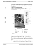
STATIM
STATIM
CASSETTE AUTOCLAVE
TROUBLESHOOTING GUIDE
Version 2.1
Original Statim Error Codes
The Statim Sterilizer should never leak steam or have water dripping from under
the machine. If either of these conditions occur, check your cassette and seal. All
leaks should be corrected before proceeding with troubleshooting procedures.
Check Cassette 1
Chamber temperature does not rise more than 2°C in three minutes. In all cases: No power to the
boiler. Check thermal fuse. Replace if necessary.
Check Cassette 2
http://www.sterilizers.com/statim-trouble-shooting-manual.html (1 of 26) [3/27/2004 9:23:44 PM]
STATIM
Failed to heat up from 95-100°C in 80 seconds. Is steam leaking from the cassette during
operation? Check seal for debris or damage. Lubricate seal using liquid hand soap. (Do not use
anti-bacterial soap,) If problem persists replace seal. Replace cassette lid or tray as needed.
Check Cassette 3
Failed to pressurize to 110°C in 70 seconds. If visible steam leaks appear repair cassette as
needed. If no leaks are visible disassemble solenoid valve and check for debris. Make sure plunger
slides smoothly in the plunger tube. Refer to Solenoid Valve Section.
Check Cassette 4
Failed to begin sterilization within 10 minutes of pressurization. Refer to explanation for Check
Cassette 3.
Check Cassette 5
Boiler went dry prematurely. May be a bad pump or boiler. Check pump using Pump Tester
Bottle (part # 01100713S). I1 pump checks good follow Check Cassette 6 explanation.
Check Cassette 6
Boiler temperature is more than 5°C higher than the chamber while sterilizing. When display
changes from "pressurization" to "sterilization", does it take longer than 10 seconds for the
pressure information (xxxKpA) to appear in the read-out'?
It is probable that water containing more than 5 ppm of total dissolved solids was used in the
machine. Boiler is contaminated. This means the inside of the boiler has accumulated excessive
mineral deposits from the use of poor quality distilled water. The boiler may be restored with a
calcium, lime and rust remover, i.e. "CLR". Refer to Reclaim Boiler Section. Note: Before
reclaiming boiler check to be sure Statim has a float switch, not a Water Quality Sensor.
Check Cassette 7
Boiler temperature is below lower limit while sterilizing. If the cassette can be removed normally
http://www.sterilizers.com/statim-trouble-shooting-manual.html (2 of 26) [3/27/2004 9:23:44 PM]
STATIM
after venting: Disassemble solenoid valve and check for debris. Make sure the plunger slides
smoothly in the plunger tube. Refer to Solenoid Valve Section.
If the cassette is hard to remove after venting:
Check for kinked exhaust tubing. Solenoid valve is failing to open. Disassemble
and check that the plunge slides smoothly in the plunger tube. Refer to Solenoid
Valve Section.
Check Cassette 8
Chamber temperature is more than 5°C higher than boiler while sterilizing.
Check for kinks in exhaust hose. Check to see if Condenser Bottle is full of hot water. When
display changes from "pressurization" to "sterilization", does it take longer than 10 seconds for the
pressure information (xxxKpA) to appear in the read-out? If the delay is more than 10 seconds,
reclaim the boiler. Refer to Reclaim Boiler Section.
Check Cassette (no number)
The chamber temperature failed to drop below 112°C within 60 seconds after the start of the
VENTING phase at the end of the cycle. Check for kinks in the exhaust hose. Check for a clogged
duct in the rear of the cassette tray. Blow out with compressed air. Check solenoid valve for
proper operation.
Service Needed The boiler temperature has exceeded 170°C, the chamber temperature has
exceeded 147°C or a thermocouple is broken. Does the "Service Needed" message appear as
soon as the cycle button is pressed, before pressing the start button? There is a broken
thermocouple. Does the "Service Needed" message appear after the start button is depressed
and cycle starts? Check pump using Pump Tester Bottle (part #01-100713S). If pump checks
good, refer to Check Cassette 6 explanation.
Select a Program is displayed in the middle of a cycle.
Check micro switch contacts. Micro switch should read less than I ohm with
cassette inserted in Statim and infinite with cassette removed.
Insert Cassette is displayed when the cassette is inserted fully and the
http://www.sterilizers.com/statim-trouble-shooting-manual.html (3 of 26) [3/27/2004 9:23:44 PM]
STATIM
START button is pressed. Check to see if chamber thermocouple is bent. Check
micro switch contacts.
New Statim Error Codes
Cycle Fault 1
The cassette temperature failed to reach 95°C within a time-out period.No power to boiler, check
thermal fuse. Replace if necessary. An extremely large steam leak. An extremely large load.
Cycle Fault 2
The cassette temperature failed to increase from 95°C to 100°C within a time-out period. An
extremely large steam leak. Replace seal or repair cassette as needed. An extremely large load.
Cycle Fault 3
The cassette has failed to pressurize and achieve a temperature of 110°C within a time-out period.
If visible steam leaks appear replace cassette seal, lid or tray as needed. If no leaks are visible
disassemble solenoid valve and check for debris. Make sure plunger slides smoothly in plunger
tube. Refer to Solenoid Valve Section. Check for leaky pressure relief valve (PRV) or check
valve.
Cycle Fault 4
The cassette has failed to achieve sterilization conditions within 15 minutes of the chamber first
reaching102'C. If visible steam leaks appear replace cassette seal, lid or tray as needed. If no leaks
are visible disassemble solenoid valve and check for debris. Make sure plunger slides smoothly in
plunger tube. Refer to Solenoid Valve Section. Check for leaky pressure relief valve (PRV) or
check valve.
Cycle Fault 5
The software causes the pump to activate at predetermined times. If a request to
pump water occurs outside of the predetermined time Cycle Fault 5 occurs.Check
pump using Pump Tester Bottle (part #01-100713S).
http://www.sterilizers.com/statim-trouble-shooting-manual.html (4 of 26) [3/27/2004 9:23:44 PM]
STATIM
Cycle Fault 6
The software has detected a steam generator (boiler) temperature 5°C greater than the chamber,
within 7.2seconds after a purge during the sterilizing phase of a cycle. Calibrate boiler. Refer to
Boiler Calibration Section
.
Cycle Fault 7
The cassette temperature has dropped 4°C below set point. If visible steam leaks appear replace
cassette seal, lid or tray as needed. Disassemble solenoid valve and check for debris. Make sure
plunger slides smoothly in plunger tube. Refer to Solenoid Valve Section.
Cycle Fault 8
The software has detected a steam generator (boiler) temperature 5'less than the chamber, within
7.2 seconds after a purge during the sterilizing phase ofa cycle. Calibrate boiler. Refer to Boiler
Calibration Section. Check for kinks in the exhaust tubing. Check to see if condenser bottle is full
of hot water.
Cycle Fault 9 N/A
Cycle Fault 10
The cassette temperature has failed to drop to 115°C during the Unwrapped or Wrapped Cycle or
the temperature has failed to drop to 110°C during the Rubber and Plastics Cycle in the purge
conditioning stage. Check for kinks in the exhaust tubing. Check for a clogged duct in the rear of
the cassette tray. Blow out with compressed air. Check solenoid valve for proper operation.
Cycle Fault 11
The cassette temperature has failed to drop to 102°C within 60 seconds of the end of a cycle
during venting. Check for kinks in the exhaust tubing. Check for a clogged duct in the rear of the
cassette tray. Blow out with compressed air. Check the solenoid valve for proper operation.
Cycle Fault 12
http://www.sterilizers.com/statim-trouble-shooting-manual.html (5 of 26) [3/27/2004 9:23:44 PM]
STATIM
This indicates a problem with the temperature measuring system. Check thermocouples, they
should read approximately 10 ohms at room temperature.
Cycle Fault 13 N/A
Cycle Fault 14
The steam generator (boiler) temperature is above 171°C during the Sterilization phase of a cycle.
Check pump using Pump Tester Bottle (part #01-100713S).
Cycle Fault 15
The cassette temperature is 3°C or more above set point during the Sterilization phase of a cycle.
Check for kinks in the exhaust tubing.
1.Check for a clogged duct in the rear of the cassette tray. Blow out with
2.Compressed air.
3.Check solenoid for proper operation.
Cycle Fault 16
The steam generator (boiler) temperature went above 171°C during the heat up phase of a cycle.
Check pump using Pump Tester Bottle (part #01-100713S).
Cycle Fault 17-18 N/A
Cycle Fault 19
The steam generator (boiler) calibration is invalid. A new calibration is required.
Calibrate the boiler. Refer to Boiler Calibration Section.
Cycle Fault 20
The pump has failed to pump water into the steam generator (boiler) during a pre-vent pump timeout. The steam generator (boiler) temperature was greater than 140°C for 3.6 seconds after the
pump was activated to pump water to cool the steam generator (boiler).
Check pump using Pump Tester Bottle (part #01-100713S).
Cycle Fault 21-24 N/A
http://www.sterilizers.com/statim-trouble-shooting-manual.html (6 of 26) [3/27/2004 9:23:44 PM]
STATIM
Cycle Fault 25
The software has failed to detect a need to pump water in 90 seconds.
No power to boiler, check thermal fuse. Replace if necessary.
Cycle Fault 26
The sterilization phase has failed to start within 3 minutes of the cassette reaching the sterilization
temperature.
Calibrate boiler. Refer to Boiler Calibration Section.
Cycle Fault 27
The internal temperature of the steam generator (boiler) has exceeded 150°C for 25 seconds.
Check pump using Pump Tester Bottle (part #01100713S).
Printer Fault
Message appears if optional printer is installed and not printing. Check for paper jam.
No message displayed and printer does not work.
Make sure that all printer cables are connected. Cables are correctly connected if the time and date
are shown on the LCD. Ensure that the paper is loaded properly. Check that the paper leaves the
paper roll from the top of the roll. This means that the treated surface of the thermal paper will be
in contact with the thermal print head.
Water Quality is Not Acceptable
The water quality sensor has detected water in the reservoir is above acceptable limits for total
dissolved solids. Drain reservoir and refill with known good distilled water. DO NOT clean boiler
with CLR.
Distilled H20 Only Same as Water Quality is Not Acceptable.
Cycle Interrupted
This message is displayed when there is a power failure in the middle of a cycle or whenever the
power is turned off after an error occurred and the STOP button is not pressed.
http://www.sterilizers.com/statim-trouble-shooting-manual.html (7 of 26) [3/27/2004 9:23:44 PM]
STATIM
Press Stop To Reset This message is displayed on all error faults. Press STOP to clear message.
Touch pads do not work
Disconnect keypad plug from PCB. Be sure blue plastic piece for keypad plug on PCB is pushed
up on the plug pins as far as possible. Reconnect keypad and check. Replace keypad if necessary.
No display or garbled display on LCD.
Check plug connections from cover to PCB. Check that microprocessor is seated firmly in socket.
Statim makes a clicking noise with cassette removed
This is caused by steam leaking from the cassette. The steam gets into the micro switch causing
the contacts to open and close and the solenoid clicks. Repair cassette leak and clicking should
stop in approximately 24 hours.
Loud buzzing noise
Clean or replace solenoid as needed.
Noise during drying cycle only
Some check valve noise is normal. Check the air filter. Replace if dirty. If filter is wet replace
check valve and compressor if necessary.
Water dripping from drain tube under Statim
Replace seal or repair cassette as needed.
Steam is escaping from Condenser Bottle vent hole
Ensure that condenser bottle is always filled to MIN line.
Steam is leaking from Push-In-Fitting at rear of Statim
Ensure that exhaust tube is fully inserted in fitting. Push past initial resistance until
tube seats.
Wraps remain wet after drying
http://www.sterilizers.com/statim-trouble-shooting-manual.html (8 of 26) [3/27/2004 9:23:44 PM]
STATIM
Ensure that cassette is clean and has been treated with Stat Dri. Drain tube must run
directly to condenser bottle with no dips or loops. Do not stack wraps. Invert mesh
rack to provide air space below wraps. Set bubble level to 4 or 5 o'clock position.
Cover Removal
Unplug Statim and remove cassette, filler cap, 4 side screws and 3 rear screws.
On the Statim 5000 the middle screw in the rear is behind the biological filter holding the filter
bracket.
With facia overhanging edge of counter or table, lift up on rear of cover until it
clears internal components, then slide cover forward about an inch.
Gently rotate the cover up and pivot it around the front left corner of the machine.
When the cover is clear of the machine, rest it on its side. Take care not to strain
the ribbon cables connecting the display and keypad.
Refer to illustration on next page
Solenoid Valve Inspection and Repair
(Honeywell solenoid only)
Ensure that the power is off. Disassembly of the solenoid valve with power on
will cause valve coil damage.
Remove retaining nut, yoke and coil from top of valve.
Unscrew the plunger tube assembly. The tube may be removed by carefully
http://www.sterilizers.com/statim-trouble-shooting-manual.html (9 of 26) [3/27/2004 9:23:44 PM]
STATIM
gripping the tube above the weld with a pair of pliers.
Remove plunger (take care not to lose the spring) and inspect plunger seal. If
plunger seal is damaged replace with solenoid repair kit (part #01-100998S).
Remove any debris found in valve body and blow air through all orifices.
Clean plunger and ensure plunger slides smoothly in plunger tube.
Reassemble solenoid valve.
Refer to illustration on next page
Draining the Reservoir Statim 2000 & 5000
If you must service the reservoir, ship a Statim or move the unit more than a short distance follow
these directions:
Statim 2000
To drain the water from the reservoir of the Statim 2000, use a high volume evacuation (HVE) hose from
a vacuum system. Insert the hose into the reservoir and allow it to suck the water out. If a vacuum system
is not available the water moat he siphoned from the reservoir. Do not turn the Statim upside down and
clump the water out.
Statim 5000
If a vacuum system is available follow the directions for a Statim 2000.
If Suction is unavailable carefully move the Statim 5000 to the edge of the work
surface. Lift the front left corner of the Statim 5000 upward and remove the drain
tube from the clip located on the underside of the unit. Gently pull the tuhc out as
far as possible so the free end can be positioned over a water container. Remove
the plug from the end of the drain tube and allow the water to drain from the
reservoir. When water no longer drips from the drain tube, replace the plug. Lift
http://www.sterilizers.com/statim-trouble-shooting-manual.html (10 of 26) [3/27/2004 9:23:44 PM]
STATIM
the front left corner of the Statim 5000 Upward, and reinsert the tube into the clip.
Push the excess length of tubing back from where it came
Changing the Cassette Seal
The cassette seal will last approximately 500 to 800 cycles. There should never be steam leaking
from the front of the Statim or water dripping from under the Statim. To change the seal follow
these directions:
1. Place the cassette lid and the new seal on a clean work surface.
2. Examine the position of the old seal in the cassette lid and arrange the new seal in the
same orientation.
3. Remove the old seal with a small screwdriver, sliding it behind the corner of the seal and
pulling the seal from the channel. Clean any residue from the seal channel.
4. Excessively lubricate the new seal using liquid hand soap (provided with new seal).
5. Align the holes in the new seal with the holes in the lid.
6. Install the holes first, then install the four corners allowing the sides to hang out. Be sure
that two indicator squares are visible in each corner.
7. Starting in the middle of along side insert the rounded edge of the seal into the channel.
Work from the middle to one corner, then from the middle to the opposite corner. Install all
four sides the same way.
8. Check to see that the seal is fully inserted into the channel on all four sides. Check the
corners to see that two indicator squares are visible in each corner. Check the two holes to
be sure that they are centered in the cutouts.
9. If there is a small steam leak or water under the unit after installing the new seal try
another cycle. It may take time to seat the new seal. If the leak persists, remove the seal and
reinstall. If unit continues to leak after installing seal for the second time try a new cassette
lid or tray.
http://www.sterilizers.com/statim-trouble-shooting-manual.html (11 of 26) [3/27/2004 9:23:44 PM]
STATIM
Care and Maintenance of the Statim Cassette
Use a non-chloride cleanser (i.e. Cameo, Zud or Bar Keepers Friend) and a green scratch pad. At
least once a week clean the inside of the lid of the cassette and the inside of the tray and the
outside edge of the lower tray. Two or three times a week take some liquid hand soap (not antibacterial) and lubricate all exposed surfaces of the seal, to keep it soft and supple. After cleaning,
rinse and dry, then apply a liberal amount of Stat Dri to the inside metal surfaces. This SciCan
product helps the water dry inside the cassette in less than one minute once the cassette is
removed from the machine. Clean the outside surface of the Statim with a mild soap and water.
The seal in the cassettes will last approximately 800 cycles and if maintained properly could last
longer.
Pump Tester Instructions
I . Disconnect the Teflon boiler inlet tube from the top of the boiler.
2. Connect the disconnected end of the inlet tube to the pump tester.
3. Activate the pump (short pins 16 & 18 on PCB) for 2 seconds to purge any air
that is trapped in the fittings. Empty any water that enters the pump tester. The
pump tester must be empty before starting the pump test.
-1. Be prepared to record the time it takes for the water level in the pump tester
bottle to reach the line marked MIN. Activate the pump by shorting pins 16 & 18
on the PCB.
5. If the water level reaches above the line marked MIN within 22-28 seconds the pump is
good.
Thermal Fuse Removal and Replacement
To remove the thermal fuse follow these steps:
1. Carefully cut the high temperature rated cable tie holding the compressor tube
http://www.sterilizers.com/statim-trouble-shooting-manual.html (12 of 26) [3/27/2004 9:23:44 PM]
STATIM
onto the check valve inlet and pull the tube off the valve.
?. Disconnect the black wire from the PCB connector terminal J1-3. This black
wire is integral to the thermal fuse assembly.
3.Trace the path of the black wire back to the base of the steam generator (boiler).
Cut all the cable ties holding the black wire.
4.Disconnect the white wire attached to the terminal on the lower half of the steam
generator (boiler).
5. Using a 3/8 inch wrench, disconnect the compression nut holding the white
Teflon tube from the top of the steam generator (boiler).
6. Using a 7/16 wrench, disconnect the compression nut holding the steam Venerator
(boiler) outlet tube to the probe bracket inlet fitting.
7. Using a 7/16 wrench disconnect the compression nut holding the steam
generator (boiler) outlet tube to the steam generator (boiler) outlet fitting.
8. Remove the two screws from the steam generator (boiler) bracket. The steam
generator (boiler) is still attached to the PCB by the thermocouple lead.
9. Gently lift and turn the steam generator (boiler) assembly onto one side to
expose the bottom of the assembly. BE CAREFUL NOT TO STRESS THE
THERMOCOUPLE LEADS.
10.Remove the screw, which attaches the steam generator (boiler) bracket to the steam
generator (boiler). This screw is shorter than the screws used to hold the bracket to the
chassis.
11. Disconnect the thermal fuse thermal from the lower power terminal on the steam
generator (boiler). Note the routing of the thermal fuse assembly between the bracket and
spacing standoffs on the bottom of the steam generator (boiler).
http://www.sterilizers.com/statim-trouble-shooting-manual.html (13 of 26) [3/27/2004 9:23:44 PM]
STATIM
To replace the thermal fuse follow these steps:
1. Connect the thermal fuse terminal to the lower power terminal on the steam
generator (boiler).
2. Attach the steam generator (boiler) bracket to the steam generator (boiler)
using the small screw. Route the wire from the fuse assembly between the bracket
and spacing standoffs on the bottom of the steam generator (boiler). The fuse must
be placed exactly between the standoffs. DO NOT PINCH OR CRUSH THE
WIRE BETWEEN COMPONENTS.
3. Carefully return and attach the steam generator (boiler) assembly to the chassis
using two screws. Start the screws into the tapped hole but do not tighten the
screws. BE CAREFUL NOT TO STRESS THE THERMOCOUPLE LEADS.
4. Connect the compression nut holding the steam generator (boiler) outlet tube to
the steam generator (boiler) outlet fitting. Tighten finger tight.
5. Connect the compression nut holding the steam generator (boiler) outlet tube to
the probe bracket inlet fitting. Tighten finger tight.
6. Connect the compression nut holding the white Teflon pump tube to the top of
the steam generator (boiler). Tighten finger tight, then continue then continue to
tighten the nut using a 3/8 inch wrench. DO NOT OVERTIGHTEN.
7. Tighten the two screws that attach the steam generator (boiler) assembly to the
chassis.
8. Using a 7/16 wrench, tighten the compression nut holding the steam generator (boiler)
outlet tube to the steam generator (boiler) outlet fitting. Tighten the compression nut holding
the steam generator (boiler) outlet tube to the probe bracket fitting also.
9. Connect the white wire to the terminal on the lower half of the steam generator
(boiler) using the screw with captive lockwasher. If the terminal appears
blackened, clean it using fine grit sandpaper.
http://www.sterilizers.com/statim-trouble-shooting-manual.html (14 of 26) [3/27/2004 9:23:44 PM]
STATIM
10. Route the black wire from the fuse assembly to the PCB connector J1-3 and connect the wire.
11. Bundle the loose wires together, using nylon cable ties every 2-3 inches.
12. Carefully push the compressor tube onto the check valve inlet and secure
the tube to the valve using a high temperature application cable tie.
Microswitch Removal and Replacement
'To remove the microswitch follow these steps:
1. Turn the main power switch OFF, and unplug the unit.
2. Disconnect the microswitch leads from the PCB block terminal positions labeled
CASSIN and carefully cut the cable ties securing the microswitch leads.
3.There may be RTV silicone sealant on the heads of the two screws securing the
microswitch to the side of the probe bracket. Trim away the excess RTV silicone and
remove the screws. Do Not remove the probe bracket to get at the screws. If you have
trouble getting at the screws disconnect the gray hose between the check valve and the
compressor and remove the four compressor mounting screws. Set the compressor off the
back of the Statim being careful not to damage the wiring.
4. Remove the microswitch.
5. Remove all RTV silicone residue from the probe bracket surface.
To replace the microswitch follow these steps:
1. Attach the replacement microswitch to the probe bracket.
2. Connect
the microswitch leads to the PCB block terminal positions labeled CASSIN.
Secure the stripped leads.
3. Route the microswitch leads the same as before and secure with nylon cable ties.
4. Plug
in the power cord and turn on the main power switch. When the cassette is fully
http://www.sterilizers.com/statim-trouble-shooting-manual.html (15 of 26) [3/27/2004 9:23:44 PM]
STATIM
inserted you should hear the solenoid valve click.
5. Once installed and functioning, a thin bead of RTV silicone sealant may be applied along
the edges of the microswitch if available.
Reclaiming Statim Boiler
DO NOT RECLAIM BOILERS ON STATIMS THAT CONTAIN A
WATER QUALITY SENSOR.
I. Remove the pressure relief valve (PRV) from the top of the boiler.
2. Pour 1 oz. of CLR into the boiler through the PRV hole.
3. Reinstall the PRV using Teflon tape.
4. With the cassette inserted start an unwrapped cycle. As soon as you hear the pump start to
run press STOP. Allow the solution to work for 15 minutes.
5. Check that the reservoir is filled with good distilled water and the condenser bottle is not
full.
6. After 15 minutes have passed, start an unwrapped cycle while
simultaneously activating the pump.
You may operate the pump by shorting pins #16 & #18 on the 20 pin
connector (P I) on the PCB.
As long as the pins are shorted the pump will run continuously and flush the
remaining deposits out of
the boiler. Allow the pump to run for 3 minutes minimum.
7. Press STOP then start a normal unwrapped cycle.
IMPORTANT
8. You may verify that the boiler contamination problem has been corrected by
confirming that the pressure information (xxxKpA) appears on the display within ten
seconds after the beginning of the sterilization phase of a cycle.
http://www.sterilizers.com/statim-trouble-shooting-manual.html (16 of 26) [3/27/2004 9:23:44 PM]
STATIM
Boiler Calibration
1. Turn the main power switch off and remove the cover. Check to see that the reservoir has
distilled water.
2. Install a juniper on terminal W I located to the left of the microprocessor on the
PCB.
3. Turn on the main power switch and insert a cassette.
4. The LCD will show CALIBRATING with two digits in the upper left corner of
the display and two digits in the upper right corner of the display. The value in
the lower left corner of the display is the difference between the steam generator
(boiler) and chamber temperatures. The value in the lower right corner of the
display is the chamber temperature.
F9> CALIBRATING <C8
+2.00°C 135.00°C
EXAMPLE
5. To start the steam generator (boiler) self-calibration cycle, hold down the UNWRAPPED
button and press the START button. The two digits in the upper left corner will change to
00> and an asterisk* will appear beside the message CALIBRATING*.
00> CALIBRATING* <C8
+2.00°C 135.00°C
EXAMPLE
6. The calibration cycle will last approximately 5 minutes. A long beep will sound indicating the
calibration is complete. The 00> in the upper left corner of the display should change to two
digits.
F6> CALIBRATING* <C8
http://www.sterilizers.com/statim-trouble-shooting-manual.html (17 of 26) [3/27/2004 9:23:44 PM]
STATIM
+2.00°C 135.00°C
EXAMPLE
7. Press the STOP button and allow the Statim to vent. When venting is complete press the
STOP button again and remove the jumper from W l . The display should say SELECT A
CYCLE. The steam generator (boiler) calibration is complete.
Selecting the Operating Language
The messages displayed on the LCD can be changed to a language of preference.
To change the current language selection, press and hold the WRAPPED button
on the front of the Statim. At the same time, turn the main power switch, in the
rear of the Statim, on.
Press the WRAPPED button again to scroll to the next language.
Press the UNWRAPPED button to scroll to the previous language.
When the desired language is displayed, press the STOP button to save the
selection and return to the regular operating mode.
Setting Time and Date on Statim with Printer
The time and date feature is available with the optional printer only. To set the time and
date follow these steps and watch the blinking cursor on the LCD.
1. Turn the main power switch off.
2. Press and hold the UNWRAPPED button on the front of the Statim. At the same time.
turn on the main power switch at the back of the Statim.
http://www.sterilizers.com/statim-trouble-shooting-manual.html (18 of 26) [3/27/2004 9:23:44 PM]
STATIM
The Display Reads
14:23 03/ 1 1 / 1998
hh: mm dd/mm/yy
EXAMPLE NOTE: The date reads day, month and year.
3. There are five fields on the display showing the hours (24 hour clock), minutes, day of
the month and year. The cycle buttons of the keypad are used to select a field for setting and
changing that field's value. The blinking cursor highlights the field currently selected.
4. To increase the value of the selected field, press the UNWRAPPED cycle button. Hold
the button down to continuously increase the value.
5. To decrease the value of the selected field, press the WRAPPED cycle button. Hold the
button down to continuously increase the value.
6. To select the next field for setting, press the RUBBER AND PLASTICS cycle button.
Press the button repeatedly to select subsequent fields.
7. To save changes and return to regular operating mode, press the STOP button.
Diagnosing Water Quality Sensor Problems
The water quality sensor detects whether or not there is sufficient water in the
reservoir, monitors conductivity of the water in the reservoir and prevents a
cycle from starting if the water measured is unsuitable. The allowed value of
dissolved solids is 5 ppm or less.
The water quality sensor can fail in one of four ways:
1. The sensor always indicates an empty reservoir.
2. The sensor always indicates a reservoir full of good quality water.
3. The sensor always indicates a reservoir full of poor quality water.
4. The sensor indicates random water quality readings.
A water quality sensor failure is caused by: poor quality water (drain reservoir
http://www.sterilizers.com/statim-trouble-shooting-manual.html (19 of 26) [3/27/2004 9:23:44 PM]
STATIM
and refill with known good distilled water), a broken or damaged water quality
sensor assembly (replace water quality sensor) or damaged electronics on the
PCB (call for a RA # and return to SciCan for PCB replacement).
Before performing diagnostic procedures verify that:
1. The reservoir is free of any debris and the water quality sensor is clean.
2. The reservoir is filled with good quality steam distilled water so that the water quality
sensor is completely submerged. If in doubt about water quality, drain the reservoir and
refill with steam distilled water containing less the 5 ppm total dissolved solids. Use water
conductivity meter (part #01-103139S).
3. The leads of the water quality sensor are securely connected to PCB terminals labeled
PROBE J4-3 and J4-4.
4. Nothing is connected to PCB terminals labeled FLOAT J4-5 and J4-6.
5. The PCB is clean and dry (both sides). Pay particular attention to terminal block J4 and
components on the upper right hand portion of the board.
Diagnostic Procedures
Always Indicates an Empty Reservoir
Using a jumper wire, short together the PROBE terminals of the PCB (J4-3 and
J4-4). Attempt to start a cycle.
1. The cycle starts. PCB is defective.
2. Message, "REFILL RESERVOIR". PCB is defective.
3. Message, "WATER QUALITY IS UNACCEPTABLE". Water quality sensor defective.
Always Indicates a Reservoir Full of Good Quality Water
Disconnect the water quality sensor leads from the PROBE terminals of the PCB
(J4-3 and J4-4). Attempt to start a cycle.
I. The cycle starts. Check PCB for a short between FLOAT terminals J4-5 and J4-6.
2. Message, "REFILL RESERVOIR". Water quality sensor defective.
3. Message, "WATER QUALITY IS UNACCEPTABLE". PCB is defective.
Always Indicates a Reservoir Full of Poor Quality Water
http://www.sterilizers.com/statim-trouble-shooting-manual.html (20 of 26) [3/27/2004 9:23:44 PM]
STATIM
Disconnect the water quality sensor leads from the PROBE terminals of the PCB
(J4-3 and J4-4). Attempt to start a cycle.
I . The cycle starts. Check PCB for a short between FLOAT terminals J4-5 and J4-6.
2. Message, "REFILL RESERVOIR". Water quality sensor defective.
3. Message, "WATER QUALITY IS UNACCEPTABLE". Check PCB for a short between
PROBE terminals J4-3 and J4-4.
Random Water Quality Readings
Start a cycle when unit is cold.
1. As the cycle proceeds and the unit warms, water reported as acceptable while the unit was
cold causes a "WATER QUALITY IS UNACCEPTABLE" message. Check water quality
using a water conductivity meter (part #01-103139S). If water quality is not within
acceptable standards or if the reservoir has been contaminated, clean the reservoir and fill
with known good steam distilled water.
2. After a few cycles, as the unit warms a, "REFILL RESERVOIR" message is displayed.
Short together PROBE terminals J4-3 and J4-4. If this clears the message and allows the
unit to run several cycles before the message recurs, the PCB is defective.
Statim 2000 Parts List
Armature 01-100561 S
Boiler (Steam Generator) 01-100726S
Bubble Level 01-1006845
Bumper (Stationary Leg) 01-1007805
Cassette Complete 100008
Cassette Lid (with Seal) 01-1008345
Cassette Seal 01-100028S
Cassette Tray 01-103475S
Cassette Tray w/Mesh Rack 100271
Check Valve 01-100574S
Compressor 0l-1005605
Compressor Filter 01-1002075
Condenser Bottle 01-100812S
Condenser Bottle wo/Condenser 01-1007245
Cover Complete 01-1005645
http://www.sterilizers.com/statim-trouble-shooting-manual.html (21 of 26) [3/27/2004 9:23:44 PM]
STATIM
Cover wo/Facia 01-1016115
Exhaust Tubing 01-100204S
Facia Complete 01-100563S
Facia Gasket 01-100842S
Facia wo/LCD 01-1035185
Isoplate 01-103856S
Keypad 01-1017075
LCD 01-1043815
Leveler Leg 01-1015535
Microswitch 01-1005715
Nylon Draintube 1" 74-100335A
PCB 01-103540S
Packaging (Box) 01-101629S
Power Cord 01-1005725
Power Switch 01-1005735
Power Wire Assy. 53-100022B
Pressure Relief Valve (PRV) 74-100294A
Probe Bracket 01-100570S
Probe Bracket Gasket 01-100865S
Pump 01-1005685
Pump Tester Bottle 01-1007135
Push In Fitting 01-100782S
Reservoir Cap (Filler Cap) 01-1017835
Reservoir w/Float 01-100565S
Reservoir w/Sensor 01-1031075
Solenoid Valve 01-100557S
Solenoid Plunger Repair Kit 01-100998S
Solenoid Coil Repair Kit 01-104303S
Strain Relief 53-100518S
Thermal Fuse 01-104366S
Waste Water Bottle Fitting 01-100735S
Water Conductivity Tester 01-103139S
Water Quality Sensor 01-103571S
Statim 5000 Parts List
Armature 01-101623S
http://www.sterilizers.com/statim-trouble-shooting-manual.html (22 of 26) [3/27/2004 9:23:44 PM]
STATIM
Biological Filter 01-102119S
Biological Filter Bracket 01-104284S
Boiler (Steam Generator) 01-101620S
Bubble Level 01-100684S
Bumper (Stationary Leg) 01-100780S
Cassette Complete 01-101613S
Cassette Handles 01-101658S
Cassette Lid (with Seal) 01-101757S
Cassette Seal 01-101649S
Cassette Tray 01-101614S
Check Valve 01-101627S
Compressor 01-101619S
Compressor Filter (cylindrical) 01-101652S
Condenser Bottle 01-100812S
Condenser Bottle wo/Condenser 01-100724S
Cover Complete 01-104300S
Cover wo/Facia 01-101625S
Exhaust Tubing 01-100204S
Facia Gasket 01-101650S
Facia wo/Printer 01-1042995
Facia wo/LCD 01-104237S
Isoplate 01-1038575
Keypad 01-101708S
LCD 01-104382S
Leveler Leg 01-101553S
Microswitch 01-101621 S
Nylon Draintube l" 74-100335A
PCB 01-104436S
Packaging (Box) 01-104446S
Plug, Drain Tubing 01-104343S
Power Cord 01-101647S
Power Switch 01-100573S
Pressure Relief Valve (PRV) 74-100294S
Printer 210000
Probe Bracket 01-101618S
Probe Bracket Gasket 01-100865S
Pump 01-101761 S
Pump Tester Bottle 01-100713S
Push In Fitting 01-101755S
Reservoir 01-101622S
http://www.sterilizers.com/statim-trouble-shooting-manual.html (23 of 26) [3/27/2004 9:23:44 PM]
STATIM
Reservoir Cap 01-101783S
Solenoid 01-1016285
Solenoid Plunger Repair Kit 01-100998S
Solenoid Coil Repair Kit 01-104303S
Thermal Fuse 01-104367S
Thermal Paper (Box of 10 Rolls) 01-101657S
Waste Water Bottle Fitting 01-100735S
Water Conductivity Tester 01-103139S
Water Quality Sensor 01-103571 S
Statim 2000 Specifications
External Size (Length x Width x Height)
17 3/4" x 16 1 /4" x 6"
Cassette Internal Dimensions
11" x 7" x 1 1/2"
Reservoir Capacity
4 liters (distilled water)
Approximately 40 cycles
Weight Without Water
46 lbs.
Power Consumption
1300 W
Optional Printer
Type: Thermal printer
Print: 20 characters per line
Speed: l line/s
Capacity: 80 cycles/roll
Cycle Time
http://www.sterilizers.com/statim-trouble-shooting-manual.html (24 of 26) [3/27/2004 9:23:44 PM]
STATIM
Unwrapped Instruments 6 minutes
Wrapped Instruments 10-12 minutes
Rubber and Plastics 20 minutes
Warranty
1 Year Parts (excluding gasket)
1 Year SciCan Labor
Statim 5000 Specifications
External Size (Length x Width x Height)
21 3/4" x 16 1 /4" x 7 1/2"
Cassette Internal Dimensions
15" x 7" x '1"
Reservoir Capacity
4 liters (distilled water)
Approximately 20 cycles
Weight Without Water
72 lbs.
Power Consumption
1300 W
Optional Printer
Type: Thermal printer
Print: 20 characters per line
Speed: I line/s
Capacity: 80 cycles/roll
Cycle Time
Unwrapped Instruments 9 minutes
Wrapped Instruments 15-18 minutes
http://www.sterilizers.com/statim-trouble-shooting-manual.html (25 of 26) [3/27/2004 9:23:44 PM]
STATIM
Rubber and Plastics 40 minutes
Heavy Duty Unwrapped 12 minutes
Warranty
I Year Parts (excluding gasket)
1 Year SciCan Labor
http://www.sterilizers.com/statim-trouble-shooting-manual.html (26 of 26) [3/27/2004 9:23:44 PM]