1
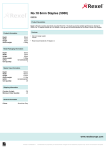
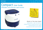
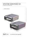
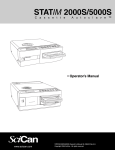
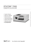
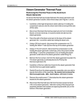
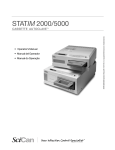
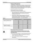
96-103913 Rev. 4.0
Required Information, Tools and Routine Maintenance
Required Information, Tools and Routine Maintenance
This STATIM service manual was created to act as reference for the
service and repair of the STATIM brand. In the interest of providing one
comprehensive global service manual, this book references numerous
STATIM units that are sold in various markets and in different geographic
locations around the globe. Because of this, you will note that there are
chapters and sections that do not apply to the STATIM unit that you may
have, or are repairing.
If you have a question about the unit you are repairing, please do not
hesitate to contact your local SciCan representative for confirmation.
Hazardous voltages are accessible when the cover is removed.
Disconnect the power cord before servicing the power mains portion of
the controller board and associated devices.
A dielectric strength test (Hi-Pot) must be performed on the STATIM if
parts associated with the mains portion of the controller board are
serviced or replaced.
A protective bonding impedance test (ground continuity) must be
performed on the STATIM if components of the protective earthing
system are changed or connections broken and remade.
The STATIM is heavy. Exercise caution and seek assistance when lifting or
carrying the units. Use only steam-process distilled water in the STATIM.
The STATIM contains electronic circuitry that is static sensitive. Always
wear a static strap when working with or near printed wiring boards. In
addition, use static footstraps, grounding mats and grounded work
surfaces when servicing microprocessor devices. Transport boards and
devices in static protected bags.
Always prime the pump to avoid Steam Generator and Thermal Fuse
damage. Never assume that the pump is primed.
Ensure that there is sufficient steam-process distilled water in the
STATIM before activating the pump.
Before a STATIM can be serviced the following special tools will be
required in addition to your service tool kit. These tools are available
from SciCan or your nearest service depot:
1.
Control Box SciCan
Part # 01-103141S
2.
Pump Tester SciCan
Part # 01-100713S
1
CONFIDENTIAL
STATIM L / 5000 / 5000S Cassette Autoclave Service Manual
Required Information, Tools and Routine Maintenance
96-103913 Rev. 4.0
Required Information, Tools and Routine Maintenance
3.
Water Conductivity Tester SciCan
Part # 01-103139S
4.
Solenoid Plunger Tube Wrench SciCan
Part # 01-103471S
5.
9/64" ball-end allen-key (hex) screwdriver SciCan Part # 01-103469S
6.
Calibration Cassette with Detatchable SciCan
Thermocouple* and Digital Thermometer*
7.
Calibration Cassette SciCan, 5000S
8.
Thermocouple* and Digital Thermometer* SciCan Part # 01-103090S
9.
Digital Voltmeter accurate to + 0.001Volt
Part # 01-03664S
Part # 01-106637S
10. Hi-Pot Tester
11. Ground Continuity Tester
12. Static Strap
13. Static Bags
14. HEISE LCD Digital Indicator Type ST-2H from Dresser Instrument
Items 1-8 are available from SciCan.
(* - the Detachable Thermocouple and Thermometer are always
serial number matched together in a kit. Both must be calibrated
together every six months by a quality calibration service bureau or
SciCan. This applies to non S units only).
Figure 1 (for non S units only)
1.
2.
3.
4.
5.
6.
7.
Calibration cassette
with detachable thermocouple
Digital thermometer
Digital voltmeter
Control box
2x7 ribbon cable, LCD connector
(connect to Controller Board header P3)
1x7 cable, keypad connector
(connect to Controller Board header P4)
2x10 moulded socket, test connector
(connect to Controller Board Header P1)
2
STATIM L / 5000 / 5000S Cassette Autoclave Service Manual
CONFIDENTIAL
96-103913 Rev. 4.0
Required Information, Tools and Routine Maintenance
Required Information, Tools and Routine Maintenance
The Control Box
When connecting the Control Box connectors to the Controller Board
note the positions of Pin #1 of the Control Box test connectors and
Pin #1 of the Controller Board headers.
There are two kinds of Control Boxes that you may encounter: one
utilizes toggle switches (shown in Figure 1), the other uses a membrane
keypad arrangement similar to the keypad on the unit.
The Control Box (4) is a service tool that allows a technician to operate
the unit while it is being serviced. The Control Box has a display (LCD)
and a variety of control switches which allow the technician to:
1.
Operate the unit independently of the keypad mechanism, to
manually activate the pump, valve or compressor, or run cycles.
2.
Make frequently used Controller Board measurements by
providing a common output and rotary switch for signal
selection during calibration. See the Calibration Instructions
in your Service Manual.
If only the display and button functions are being used, connect the LCD
cable (5) to Controller Board connector P3, the keypad cable (6) to
Controller Board connector P4 and power the Statim ON.
If the override or measurement functions are being used, connect the
2x10 cable (7) to connector P1 of the Controller Board in addition to the
other cables (5 and 6).
When using a toggle switch model of the Control Box, turn the switch to
the ON position to activate the desired device. To turn the device OFF
turn the switch to the AUTO position. To select, start and / or stop a
cycle, activate the appropriate push-button switch on top of the Control
Box. Calibration utilizes the Select out +, Select out - jacks and a setting
on the Rotary Switch to set the calibration operation desired for Type A
Controller Boards. See Thermocouple Calibration.
When using a keypad model of the Control Box, the keypad switch must
be held down to turn the desired device ON. Vref measurements utilize
test leads, the Vref + and Vref - banana jacks and a voltmeter hooked up
in series. Calibration utilizes the Select out + and Select out - jacks, test
leads and a setting on the Rotary Switch to set the calibration operation
desired for Type A Controller Boards.
3
CONFIDENTIAL
STATIM L / 5000 / 5000S Cassette Autoclave Service Manual
Required Information, Tools and Routine Maintenance
96-103913 Rev. 4.0
Required Information, Tools and Routine Maintenance
The keypad of this Control Box provides the same features as a STATIM
keypad. See Thermocouple Calibration.
The Control Box is for use with STATIM products ONLY.
Preventative Maintenance Schedules
To ensure trouble-free performance, both the operator and the dealer
must follow a preventative maintenance schedule.
Operator
Daily
Weekly
Every
six months
Cassette
Wash the interior of the cassette with
chlorine-free dishwashing detergent
or soap. Rinse thoroughly with water.
Water Reservoir
Drain Daily
Waste Bottle
Empty the waste bottle every time you
refill the reservoir. Fill with tap water
up to MIN line. You can also add some
chlorine-free disinfectant.
Air Filter
Check the air filter for dirt and
moisture. Replace if dirty.
Call for service if wet.
Biological Air Filter
Check the air filter for dirt and
moisture. Replace if dirty.
Call for service if wet.
Air Filter
Replace every 500 cycles or six
months (whichever comes first).
Biological Air Filter
Replace every 500 cycles or six
months (whichever comes first).
Cassette Seal
Replace every 500 cycles or six
months (whichever comes first).
4
STATIM L / 5000 / 5000S Cassette Autoclave Service Manual
CONFIDENTIAL
96-103913 Rev. 4.0
Required Information, Tools and Routine Maintenance
Required Information, Tools and Routine Maintenance
Technician
Once a
Year
Cassette
Check the tray, lid and seal for
damage. Replace if necessary.
Air Filters
Check the filters. Replace if dirty.
Solenoid Valve
Inspect the valve and clean if dirty.
Replace the plunger if defective.
Pump
Clean the filters, replace if dirty.
Check Valve
Remove the air compressor tube
from the check valve inlet while
running a cycle. Make sure no steam
is leaking from the valve. Replace if
there are any leaks.
Solenoid Valve
Inspect the valve and clean if dirty.
Replace the plunger if defective.
Water Reservoir
Check the reservoir for dirt. Clean
and rinse with steam process distilled
water if necessary.
Calibration
Calibrate the unit.
Cleaning the Cassette
Keeping the STATIM cassette clean is good clinical practice and assists
in the function of the unit. SciCan recommends that the interior surface
be cleaned at least once a week. Use dishwashing soap or a mild
detergent that does not contain chlorine. Scrub the inside of the cassette
with a cleaning pad designed for use with Teflon™ coated surfaces. After
scouring, rinse thoroughly with water to remove all traces of the
detergent. Cleaning the inside of your cassette is very important if you
regularly sterilize lubricated instruments. Coating the entire inside
surface with STAT-DRI drying agent induces water to form an even coat
on the inside surface, without beading. The water in contact with the hot
cassette surfaces also evaporates much more efficiently. Spotting is
minimized and instruments dry much better. STAT-DRI should be applied
every 10 cycles, and after every cassette cleaning.
STAT-DRI is available from SciCan in a 2 ounce bottle (SciCan Part #
2OZ473) or an 8 ounce bottle (SciCan Part #8OZ473).
5
CONFIDENTIAL
STATIM L / 5000 / 5000S Cassette Autoclave Service Manual
Required Information, Tools and Routine Maintenance
96-103913 Rev. 4.0
Required Information, Tools and Routine Maintenance
2
5
1
6
1.
2.
3.
4.
5.
6.
3
Cassette seal
Holes in seal
Lid of cassette
Channel
Liquid seal lubricant
Locating tabs
4
Figure 3
6
STATIM L / 5000 / 5000S Cassette Autoclave Service Manual
CONFIDENTIAL
96-103913 Rev. 4.0
Required Information, Tools and Routine Maintenance
Required Information, Tools and Routine Maintenance
Replacing the Cassette Seal
To ensure optimum performance of your STATIM cassette autoclave,
change the cassette seal every 500 cycles or every six months,
whichever comes first. Replacement seals are available from SciCan
(order number 01-101649S for STATIM 5000S).
To change the cassette seal, follow these steps:( see Figures 3, 4)
Place the cassette lid and the new seal on a clean work surface.
Examine the position of the old seal in the cassette lid and arrange the
new seal in the same orientation, next to the lid.
Remove the old seal and discard. Clean any
residue out of the seal channel and flush out
the channel with distilled water.
Lubricate the new seal with the liquid seal
lubricant provided.
Insert the rounded edge of the seal under the
round lip of the lid. Align the holes in the new
seal with the holes in the lid.
NOTE: At every corner, two square nibs
should be visible.
Ensure the seal is completely inserted.
Feel around the periphery to ensure the seal
is securely in place.
Figure 4
NOTE: During a cycle, steam may appear
between the lid and the tray.
Be careful. The metal parts will be hot, and the
cassette may contain hot steam.
7
CONFIDENTIAL
STATIM L / 5000 / 5000S Cassette Autoclave Service Manual
Required Information, Tools and Routine Maintenance
96-103913 Rev. 4.0
Required Information, Tools and Routine Maintenance
Cleaning the Enclosure
Use a soft cloth moistened with a mild cleaning solution or a mild
Disinfectant to clean all outside surfaces. Do not use solvents or
harsh chemicals.
steam generator
Air Flow diagram
cylindrical
air filter
compressor
compressor
steam generator
cylindrical
air filter
bacteria-retentive
air filter
Figure 5
cylindrical air filter located behind bacteria
retentive filter / bracket assembly
Figure 6
1
1.
2.
3.
4.
5.
2
3
5
4
tube A
bacteria-retentive air filter
filter bracket
tube B
cylindrical air filter
8
STATIM L / 5000 / 5000S Cassette Autoclave Service Manual
CONFIDENTIAL
96-103913 Rev. 4.0
Required Information, Tools and Routine Maintenance
Required Information, Tools and Routine Maintenance
Air Filters – STATIM 5000 / 5000S
Never re-use an old filter. Never run the unit without a clean filter
in place.
After each sterilization cycle the compressor forces air through the
cassette to rid it of steam and to dry the instruments. The air is drawn
into the Compressor (see Figure 5) through one or two filters located at
the back of the unit, depending upon which unit is being serviced. The
STATIM units draw air through a circular air filter located behind the
cover plate on the Compressor, at the rear of the unit. The STATIM is
manufactured with an additional bacteria-retentive air filter, held in a
bracket, attached to the rear cover of the unit. (See STATIM Cover
Removal and Replacement). Filters should be changed every 500
cycles or six months (whichever comes first).
Cylindrical Air Filter and Bacteria-Retentive Filter
To change both filters, follow these steps (see Figure 6):
1.
Disconnect tube A (1) from the bacteria-retentive filter (2) and
remove the filter from the filter bracket (3). As you remove the filter
from the bracket, note the orientation of the arrow mark on the filter.
2.
When the filter is free of the bracket, carefully disconnect tube B (4)
from the filter. Do not pull on this tube.
3.
Unscrew the cylindrical air filter (5). Discard the old filter.
4.
Screw the new filter, finger tight only, into place.
5.
Before installing the replacement bacteria-retentive filter check that
the arrow mark on the filter matches the direction of the arrow on
the bracket. Push the left hand filter fitting into tube B (4).
6.
Gently press the replacement filter into the filter bracket. The arrow
mark on the filter is facing out and pointing to the left.
7.
Re-connect the tube A (1) to the right hand filter fitting.
Cylindrical Air Filter Only
To change the cylindrical air filter only, follow these steps (see Figure 6):
1.
Unscrew the cylindrical air filter (5) in a counter clock-wise
direction.
9
CONFIDENTIAL
STATIM L / 5000 / 5000S Cassette Autoclave Service Manual
Required Information, Tools and Routine Maintenance
96-103913 Rev. 4.0
Required Information, Tools and Routine Maintenance
2.
Discard the old filter.
3.
Screw the new filter, finger tight only, into place.
Draining the Reservoir
If you must service the reservoir, ship the Statim, or move the unit more
than a short distance, follow these directions:
4
■
1
■
3
■
2
■
Figure 7
1.
To drain the water from the reservoir, carefully move the STATIM to
the edge of the work surface. The front leveler feet (1) should be
approximately 12 mm (1/2 inch) from the edge so the unit remains
securely seated on the work surface.
2.
Lift the front left corner of the STATIM upward and remove the drain
tube (2) from the clip (3) located on the underside of the unit.
Gently pull the tube out as far as possible so the free end can be
positioned over a container when the unit is lowered back to the
work surface.
3.
Remove the stopper (4) from the end of the drain tube and allow the
water to drain from the reservoir. When water no longer drips from
the drain tube, replace the stopper.
4.
Lift the front left corner of the Statim upward and re-insert the tube
into the clip on the underside of the unit. Push the excess length of
tubing back from where it came.
Shipping the STATIM
If you must ship the STATIM, follow these directions:
1.
Drain the reservoir. See, Draining the Reservoir.
2.
Screw in each leveler foot completely.
3.
Repack your STATIM in the original packing materials.
4.
Specify heated and insured shipping.
10
STATIM L / 5000 / 5000S Cassette Autoclave Service Manual
CONFIDENTIAL
96-103913 Rev. 4.0
Required Information, Tools and Routine Maintenance
Required Information, Tools and Routine Maintenance
Safety Compliance
When a STATIM is serviced, the safety criteria as specified by applicable
international safety standards and applicable national, state, provincial,
and regional laws and regulations must be observed and maintained.
Dielectric Strength Test (Hi-Pot)
Exercise caution while performing this test. Hazardous voltages are
present. Do not touch the unit, nor allow the unit to touch any conductive
surfaces during the test.
When components of the mains part are serviced or replaced, the
dielectric strength of the electrical insulation between the mains and
user-accessible conductive parts must be tested to ensure continued
compliance of the unit with applicable international safety standards.
Perform the test using a dielectric strength (hi-pot) tester operated in
accordance with the manufacturer’s written instructions using the
following parameters:
Test Voltage: 1500Vac RMS
Test Voltage Frequency: 50 or 60 Hz
Test Voltage Rise Time: 2 seconds (maximum)
Duration at Test Voltage: 2 seconds (minimum)
Connection Points:
a. Unit chassis
b. Line and neutral terminals of the mains plug connected together.
For the unit being tested to pass, there must be no breakdown of the
Insulation nor any flashover.
Protective Bonding Impedance Test (Ground Continuity)
Applicable international safety standards require that the impedance
between the protective conductor terminal of the power entry connector
and any user-accessible conductive parts not exceed 0.1 ohms. If any
components of the protective earthing system are changed or any
connections of that system are broken and remade, the impedance of
11
CONFIDENTIAL
STATIM L / 5000 / 5000S Cassette Autoclave Service Manual
Required Information, Tools and Routine Maintenance
96-103913 Rev. 4.0
Required Information, Tools and Routine Maintenance
the Protective bonding must be tested and verified as being less than
0.1 ohms Using test equipment and procedures in compliance with
applicable International safety standards and national, state, provincial,
and regional Laws and regulations.
Chamber Temperature Mapping
Test outcomes have found the highest temperature spot in the 5000S
cassette chamber is located in the UPPER / RIGHT / FRONT corner
and the lowest temperature spot is located at the UPPER / RIGHT /
REAR of the cassette on the right side.
Water Conductivity Testing
Water conductivity testing determines the amount of dissolved solids in
the steam-process distilled water used in the STATIM unit. Use only
steam-process distilled water having 5 ppm or less dissolved solids or a
conductivity of less than 10 µS / cm. Follow the manufacturer’s
instructions to test water conductivity using SciCan conductivity meter,
part #01-103139S, or any other equivalent meter.
Temperature has a significant effect on conductivity readings, therefore
the water being tested should be at room temperature.
Water Conductivity
Measurement
12
STATIM L / 5000 / 5000S Cassette Autoclave Service Manual
CONFIDENTIAL
96-103913 Rev. 4.0
Required Information, Tools and Routine Maintenance
Required Information, Tools and Routine Maintenance
13
CONFIDENTIAL
STATIM L / 5000 / 5000S Cassette Autoclave Service Manual
Required Information, Tools and Routine Maintenance
96-103913 Rev. 4.0
Required Information, Tools and Routine Maintenance
14
STATIM L / 5000 / 5000S Cassette Autoclave Service Manual
CONFIDENTIAL
4
3
2
B
SOLENOID VALVE
A
BLK #14 AWG
WHT #14 AWG
2A
1A
N
P
LINE FILTER
POWER SWITCH
2
1
#22 AWG
#22 AWG
WHT #20 AWG
BLK #20 AWG
GRN #20 AWG
GRN # 14 AWG
PUMP
BOILER
COMPRESSOR
BLK #14 AWG
WHT #14 AWG
WHT #22 AWG
BLK #22 AWG
SILICONE SLEEVE
& KAPTON TAPE
THERMAL FUSE
J1
N/PUMP
L/PUMP
N/BLR
L/BLR
LINE
NEUTRAL
VALVE
N/COMP
L/COMP
WATER
QUALITY
SENSOR
GRN #18 AWG
PCB POWER IN CABLE ASSEMBLY
B
BLUE # 24 AWG
RED # 24 AWG
7
J4
CASSIN
FLOAT
PROBE
J5
J6
P4
P3
P2
KEYPAD
LCD CABLE ASSEMBLY
DISPLAY
PRINTER
PRINTER CONTROL CABLE
ASSEMBLY
THERMOCOUPLE UNGROUNDED
C
N/A
+
TOLERANCE: .005"
-
C
DIMENSIONS IN INCHES
UNLESS OTHERWISE SPECIFIED:
MATERIAL
FILE
APPROVED
CHECKED
DRAWN
DESIGNED
G. YIN
A. SZCZUROWSKI
G. YIN
S. WEINACHT
04-108528-1.DWG
DATE
15 NOV.03
25 NOV.03
27 NOV.03
03 DEC.03
NAME
SSB
STATIM 5000
PRODUCT
CONSULT SCICAN DESIGN ENG. FOR CLARIFICATION
DO NOT SCALE DRAWING
STERILIZER CONTROLLER PCB
J3
BLACK #24 AWG
WHITE #24 AWG
THERMOCOUPLE UNGROUNDED
MICROSWITCH
OP2
GND
+5
OP1
GND
IN1
1
BLK #14 AWG
WHT #14 AWG
04-108528
+Y
-R
+Y
-R
BLR
CONFIDENTIAL
CHM
PROPERTY AND IS THE PROPERTY OF SCICAN. IT IS TO BE TREATED AS STRICTLY
THE CONTENT OF THIS DOCUMENT IS SCICAN INTELLECTUAL
DISCLOSED, REPRODUCED OR USED EXCEPT AS AUTHORIZED IN WRITING BY SCICAN IN CONNECTION
CONFIDENTIAL AND IS NOT TO BE
COPYRIGHT 1994 SCICAN
WITH THE MANUFAC
TURE, MAINTENANCE AND USE OF THE SCICAN EQUIPMENT
TO WHICH IT PERTAINS.
ECO
AS
APP
SHEET
SCALE
.
1
OF
N/A
1
TORONTO, ONTARIO, CANADA
SSB
04-108528
PART NUMBER
D
DATE
25 NOV.03
DIVISION OF LUX
& ZWINGENBERGER LTD
NOTES
INITIAL RELEASE
WIRING DIAGRAM - STATIM 5000
PART NAME
03-0957
1
REV
MEMBRANE KEYBOARD
LIQUID CRYSTAL DISPLAY
OPTIONAL PRINTER
(SHOWN FOR REFERENCE ONLY)
ARMATURE ASSEMBLY
D
4
3
2
1
96-103913 Rev. 4.0
Required Information, Tools and Routine Maintenance
Required Information, Tools and Routine Maintenance
15
STATIM L / 5000 / 5000S Cassette Autoclave Service Manual
4
3
2
1
B
SOLENOID VALVE
1A
N
P
LINE FILTER
POWER SWITCH
2A
1
BLK #14 AWG
WHT #14 AWG
WHT #22 AWG
BLK #22 AWG
SILICONE SLEEVE
& KAPTON TAPE
THERMAL FUSE
A
1. TERMINAL CONNECTION: MALE HEADER OF
TRANSDUCER PCB CONNECTS TO FEMALE
HEADER OF CONTROLLER PCB.
BLK #14 AWG
WHT #14 AWG
2
#22 AWG
#22 AWG
GRN # 14 AWG
PUMP
BOILER
COMPRESSOR
B
BLUE # 24 AWG
RED # 24 AWG
J1
N/PUMP
L/PUMP
N/BLR
L/BLR
LINE
NEUTRAL
VALVE
N/COMP
L/COMP
WATER
QUALITY
SENSOR
GRN #18 AWG
J3
CASSIN
J5
J6
P4
P3
P2
KEYPAD
LCD CABLE ASSEMBLY
DISPLAY
PRINTER
+
TOLERANCE: .005"
-
C
DIMENSIONS IN INCHES
UNLESS OTHERWISE SPECIFIED:
N/A
FILE
APPROVED
CHECKED
DRAWN
DESIGNED
15 NOV.03
25 NOV.03
G. YIN
A. SZCZUROWSKI
G. YIN
S. WEINACHT
04-108529-1.DWG
27 NOV.03
03 DEC.03
DATE
NAME
SSB
STATIM 5000S
PRODUCT
CONSULT SCICAN DESIGN ENG. FOR CLARIFICATION
MATERIAL
GND
V+
SIG
PRINTER CONTROL
CABLE ASSEMBLY
TRANSDUCER PCB
THERMOCOUPLE UNGROUNDED
DO NOT SCALE DRAWING
STERILIZER CONTROLLER PCB
3
J4
BLACK #24 AWG
WHITE #24 AWG
THERMOCOUPLE UNGROUNDED
MICROSWITCH
PCB POWER IN CABLE ASSEMBLY
BLK #14 AWG
WHT #14 AWG
04-108529
OP2
GND
+5
OP1
GND
IN1
WHT #22 AWG
BLK #22 AWG
GRN #22 AWG
FLOAT
PROBE
C
+Y
-R
+Y
-R
BLR
STATIM L / 5000 / 5000S Cassette Autoclave Service Manual
CHM
SEE NOTE 1
PROPERTY AND IS THE PROPERTY OF SCICAN. IT IS TO BE TREATED AS STRICTLY
THE CONTENT OF THIS DOCUMENT IS SCICAN INTELLECTUAL
DISCLOSED, REPRODUCED OR USED EXCEPT AS AUTHORIZED IN WRITING BY SCICAN IN CONNECTION
CONFIDENTIAL AND IS NOT TO BE
COPYRIGHT 1996 SCICAN
WITH THE MANUFAC
TURE, MAINTENANCE AND USE OF THE SCICAN EQUIPMENT
TO WHICH IT PERTAINS.
ECO
APP
SCALE
SHEET
.
OF
N/A
1
1
TORONTO, ONTARIO, CANADA
04-108529
PART NUMBER
D
DATE
25 NOV.03
DIVISION OF LUX
& ZWINGENBERGER LTD
NOTES
INITIAL RELEASE
WIRING DIAGRAM - STATIM 5000S
SSB
PART NAME
03-0957
1
REV
MEMBRANE KEYBOARD
LIQUID CRYSTAL DISPLAY
AS
PRESSURE
TRANSDUCER
OPTIONAL PRINTER
BLACK #24 AWG
RED #24 AWG
BLUE #24 AWG
(SHOWN FOR REFERENCE ONLY)
ARMATURE ASSEMBLY
D
4
3
2
1
Required Information, Tools and Routine Maintenance
96-103913 Rev. 4.0
Required Information, Tools and Routine Maintenance
16
CONFIDENTIAL
96-103913 Rev. 4.0
Required Information, Tools and Routine Maintenance
Document Change Record
Document 96-103913
Title: Required Information and Tools
Revision
ECO
Notes
Date
4.0
04-0020
Updated chapter as per prEN13060 requirements.
January 16, 2004
3.0
99-0059
Added 5000S references. Added Flow Schematic and wiring
99-0059 diagram
April 14, 1999
2.0
98-0290
Line art replaced with photos. Image of keypad style control
box added. Cassettes added. 5000S references added.
Calibration cassette Pressure fitting added. Added reference
to EN 61010 and changed Hi-Pot test voltages.
January 24, 1998
1.0
96-088
Initial Release
May 29, 1996
17
CONFIDENTIAL
STATIM L / 5000 / 5000S Cassette Autoclave Service Manual