1
VLT® 2800, VLT® 6000 HVAC and VLT® 8000 AQUA Modbus RTU
■
Contents
Overview
6
6
6
6
6
6
7
Installation and Setup
8
8
9
9
9
.............................................................................................................
Introduction ............................................................................................................
About This Manual .................................................................................................
Assumptions ..........................................................................................................
What You Should Already Know .............................................................................
Modbus RTU Overview ..........................................................................................
VLT 2800, VLT 6000 and VLT 8000 with Modbus RTU ...........................................
..................................................................................
Network Connection .............................................................................................
Hardware Setup VLT 2800 .....................................................................................
Hardware Setup VLT 6000 and VLT 8000 ...............................................................
EMC Precautions ...................................................................................................
Modbus RTU Programming
.......................................................................
VLT 2800 Parameter Settings for Modbus Communication .....................................
VLT 6000 Parameter Settings for Modbus Communication .....................................
Installation and Set-up VLT 8000 ............................................................................
VLT 8000 Parameter Settings for Modbus Communication .....................................
10
10
12
13
13
Network Configuration
................................................................................. 14
Remote Terminal Unit ............................................................................................. 14
Modbus RTU Message Framing Structure .............................................................. 14
Parameter Handling
.......................................................................................
Parameter Handling ................................................................................................
Storage of Data ......................................................................................................
Register Maps VLT 2800 ........................................................................................
Register Maps VLT 6000 ........................................................................................
Register Maps VLT 8000 ........................................................................................
Process Data .........................................................................................................
Status Coil Maps ....................................................................................................
Control Word Bit Descriptions for VLT 2800 ............................................................
Status Word Bit Description for VLT 2800 ...............................................................
Control Word Bit Descriptions VLT 6000 / VLT 8000 ...............................................
Status Word Bit Descriptions VLT 6000 / VLT 8000 ................................................
Serial communication reference ..............................................................................
Present output frequency .......................................................................................
Supported Modbus RTU Function Codes
16
16
16
17
18
19
20
20
20
21
23
25
26
26
......................................... 28
Exception Codes
............................................................................................. 31
Exception Code Tables .......................................................................................... 31
Appendix A - Examples
MG.10.S2.02 - VLT is a registered Danfoss trademark
............................................................................... 32
1
VLT® 2800, VLT® 6000 HVAC and VLT® 8000 AQUA Modbus RTU
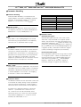
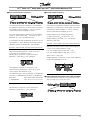
VLT 2800 Series
195NA009.17
■ Software Version VLT 2800, VLT 6000 and VLT 8000
Operating instructions
Software version: 2.8x
VLT 6000 HVAC
175ZA691.14
These operating instructions can be used for all VLT 2800
Series frequency converters with software version 2.8x.
The software version number can be seen from parameter
640 Software version no.
Operating Instructions
Software version: 3.0x
These Operating Instructions can be used for all VLT 6000
HVAC frequency converters with software version 3.0x.
The software version number can be seen from parameter
624.
2
MG.10.S2.02 - VLT is a registered Danfoss trademark
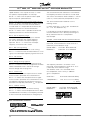
VLT 8000 AQUA
176FA145.13
VLT® 2800, VLT® 6000 HVAC and VLT® 8000 AQUA Modbus RTU
Safety - Modbus
RTU
Operating Instructions
Software version: 1.5x
These Operating Instructions can be used for all VLT 8000 AQUA
frequency converters with software version 1.5x.
The software version number can be seen from parameter 624
Software version no.
■ High Voltage Warning
Rotating shafts and electrical equipment
can be hazardous. Therefore, it is strongly
recommended that all electrical work
conform to National Electrical Code (NEC) and all local
regulations. Installation, start-up and maintenance
should be performed only by qualified personnel.
Motor control equipment and electronic controls are
connected to hazardous line voltages. When servicing
■ Warnings Against Unintended Start
1. While the frequency converter is connected
to the AC line, the motor can be brought to
a stop by means of external switch closures,
serial bus commands or references. If personal
safety considerations make it necessary to
ensure that no unintended start occurs, these
stops are not sufficient.
2. During programming of parameters, the motor
may start. Be certain that no one is in the
frequency converters and electronic controls, there will
be exposed components at or above line potential.
Extreme care should be taken to protect against shock.
Stand on an insulating pad and make it a habit to use
only one hand when checking components. Always
work with another person in case of an emergency.
Disconnect power whenever possible to check controls
or to perform maintenance. Be sure equipment is
properly grounded. Wear safety glasses whenever
working on electric control or rotating equipment.
area of the motor or frequency converter driven
equipment when changing parameters
3. A motor that has been stopped may start
unexpectedly if faults occur in the electronics
of the frequency converter, or if an overload, a
fault in the supply AC line or a fault in the motor
connection or other fault clears.
4. If the "Local/Hand" key is activated, the motor
can only be brought to a stop by means of the
"Stop/Off" key or an external safety interlock.
■ Electrostatic discharge (ESD)
Electronic components are sensitive to
electrostatic discharge (ESD). ESD can
reduce performance or destroy sensitive
electronic components. Follow proper ESD procedures
during installation or servicing to prevent damage.
MG.10.S2.02 - VLT is a registered Danfoss trademark
3
VLT® 2800, VLT® 6000 HVAC and VLT® 8000 AQUA Modbus RTU
VLT 2800
Warning:
It can be extremely dangerous to touch the electrical parts even when the mains
supply has been disconnected.
Also ensure that other voltage inputs are disconnected from load sharing through the
DC bus.
Wait at least 4 minutes after the input power has been removed before servicing the
drive.
195NA139.10
Warning:
Touching the electrical parts may be fatal - even after the equipment has been
disconnected from mains.
175HA490.11
VLT 6000 HVAC
Using VLT 6002 - 6005, 200-240 V: Wait at least 4 minutes
Using VLT 6006 - 6062, 200-240 V: Wait at least 15 minutes
Using VLT 6002 - 6005, 380-460 V: Wait at least 4 minutes
Using VLT 6006 - 6072, 380-460 V: Wait at least 15 minutes
Using VLT 6102 - 6352, 380-460 V: Wait at least 20 minutes
Using VLT 6400 - 6550, 380-460 V: Wait at least 15 minutes
Using VLT 6002 - 6006, 525-600 V: Wait at least 4 minutes
Using VLT 6008 - 6027, 525-600 V: Wait at least 15 minutes
Using VLT 6032 - 6275, 525-600 V: Wait at least 30 minutes
4
MG.10.S2.02 - VLT is a registered Danfoss trademark
VLT® 2800, VLT® 6000 HVAC and VLT® 8000 AQUA Modbus RTU
Warning:
176FA159.12
VLT 8000 AQUA
MG.10.S2.02 - VLT is a registered Danfoss trademark
Safety - Modbus
RTU
Touching the electrical parts may be fatal - even after the equipment has
been disconnected from line.
VLT 8006-8062, 200-240 V:
wait at least 15 minutes
VLT 8006-8072, 380-480 V:
wait at least 15 minutes
VLT 8102-8352, 380-480 V:
wait at least 20 minutes
VLT 8450-8600, 380-480 V:
wait at least 15 minutes
VLT 8002-8006, 525-600 V:
wait at least 4 minutes
VLT 8008-8027, 525-600 V:
wait at least 15 minutes
VLT 8032-8300, 525-600 V:
wait at least 30 minutes
5
VLT® 2800, VLT® 6000 HVAC and VLT® 8000 AQUA Modbus RTU
■ Overview
■ Introduction
These operating instructions provide comprehensive
instructions on the installation and set up of the
Modbus RTU for VLT® 2800, VLT® 6000 HVAC
and VLT® 8000 AQUA Frequency Converter to
communicate over a Modbus network.
For specific information on installation and operation
of the frequency converter, refer to the VLT® 2800
Operating Instructions, MG.28.AX.YY / VLT® 6000
HVAC Operating Instructions, MG.61.AX.YY /
VLT® 8000 Operating Instructions, MG.80.AX.YY.
■ About This Manual
These operating instructions are intended to be used for
both instruction and reference. It only briefly touches on
the basics of the Modbus protocol whenever necessary
to gain an understanding of the Modbus RTU.
These operating instructions are also intended to
serve as a guideline when you specify and optimise
your communication system. Even if you are an
experienced Modbus programmer, it is suggested
that you read these operating instructions in its
entirety before you start programming since important
information can be found in all sections.
■ Assumptions
These operating instructions assume that you have
a controller that supports the interfaces in this
document and that all the requirements stipulated in
the controller, as well as the frequency converter, are
strictly observed, along with all limitations therein.
other devices, and how errors will be detected and
reported. It establishes a common format for the
layout and contents of message fields.
During communications on a Modbus RTU network,
the protocol determines how each controller will know
its device address, recognise a message addressed
to it, determine the kind of action to be taken, and
extract any data or other information contained in
the message. If a reply is required, the controller will
construct the reply message and send it.
Controllers communicate using a master-slave
technique in which only one device (the master) can
initiate transactions (called queries). The other devices
(slaves) respond by supplying the requested data to the
master, or by taking the action requested in the query.
The master can address individual slaves, or can
initiate a broadcast message to all slaves. Slaves
return a message (called a response) to queries that
are addressed to them individually. Responses are not
returned to broadcast queries from the master.
The Modbus RTU protocol establishes the format
for the master’s query by placing into it the device
(or broadcast) address, a function code defining
the requested action, any data to be sent, and an
error-checking field. The slave’s response message
is also constructed using Modbus protocol. It
contains fields confirming the action taken, any data
to be returned, and an error-checking field. If an
error occurred in receipt of the message, or if the
slave is unable to perform the requested action, the
slave will construct an error message and send it
in response or a time-out will occur.
■ What You Should Already Know
The Modbus RTU is designed to communicate with any
controller that supports the interfaces defined in this
document. It is assumed that you have full knowledge
of the capabilities and limitations of the controller.
■ Modbus RTU Overview
Modbus RTU (Remote Terminal Unit) protocol defines
a message structure that controllers will recognise
and use, regardless of the type of physical networks
over which they communicate. It describes the
process a controller uses to request access to another
device, how it will respond to requests from the
6
MG.10.S2.02 - VLT is a registered Danfoss trademark
VLT® 2800, VLT® 6000 HVAC and VLT® 8000 AQUA Modbus RTU
■ VLT 2800, VLT 6000 and VLT 8000 with Modbus RTU
The frequency converter communicates in Modbus
RTU format over an EIA-485 (formerly RS-485)
network. Modbus RTU allows access to the frequency
converter’s Control Word and Bus Reference.
Overview
The Control Word allows the Modbus master to control
several important functions of the frequency converter:
• Start
• Stop the frequency converter in several ways:
Coast stop
Quick stop
DC Brake stop
Normal (ramp) stop
• Reset after a fault trip
• Run at a variety of preset speeds
• Run in reverse
• Change the active setup
• Control the frequency converter’s two built-in relays
The Bus Reference is commonly used for speed control.
It is also possible to access the parameters, read
their values, and, where possible, write values to
them. This permits a range of control possibilities,
including controlling the frequency converter’s setpoint
when its internal PID controller is used.
MG.10.S2.02 - VLT is a registered Danfoss trademark
7
VLT® 2800, VLT® 6000 HVAC and VLT® 8000 AQUA Modbus RTU
■ Installation
and Setup
Modbus RTU is a transmission protocol developed for
process control systems. The Modbus standard does
not specify the physical interface for the protocol i.e.
a number of different interfaces can be chosen.
The Modbus RTU protocol is based on the build-in
RS-485 (EIA-485) interface.
RS-485 is a two-wire bus-interface that allows
multi-drop network topology i.e. nodes can
be connected as a bus, or via drop cables
from a common trunk line.
A total number of 32 nodes can be connected to
one Modbus RTU network segment, and a total of
247 nodes in a network are supported.
Network segments are divided with repeaters.
Please note that each repeater counts for a node
in each segment it’s installed.
Every node connected to the same network must have
an unique nodes address, across all segments.
Every segment must be terminated in both ends,
either with the termination switches (switch 2 &
3) of the VLT 6000 / VLT 8000 or with a biased
termination resistor network.
For bus-cabling always use cable of screened
twisted pair type (STP), and make sure to follow
good common installation practice.
Make sure the screen of the Modbus RTU cable must
always be connected to ground at all nodes.
It is very important to have a low impedance ground
connection of the screen, also at high frequencies.
This can be obtained by connecting a large surface
of the screen to ground, for example by means of
a cable clamp or a conductive cable gland.
Particularly in installation where there is long
cable lengths, it can be necessary to apply
potential equalizing cables to ensure same ground
potential throughout the network.
To prevent impedance mismatch, always use cable
of same type across the entire network.
When connecting a motor to the frequency converter,
make sure always to use screened motor cable.
Address range:
1 - 247
Baud Rate:
300 - 9600 bps
Cable:
Screened twisted pair (STP)
Impedance: 120 Ohm
Cable length:
Max. 1200 m (including drop lines)
Max. 500 m station-to-station
■ Network Connection
Connect the frequency converter to the Modbus RTU in
accordance with the following procedure (see Figure 1).
1. Connect signal wires to terminal 68 (P+) and
terminal 69 (N-) on main control board of
the frequency converter.
2. The shield of the cable must be connected
to the cable clamps.
NB!:
It is recommended to use shielded, twisted-pair
cables to reduce noise between conductors.
Figure 1 Network Terminal Connection
8
MG.10.S2.02 - VLT is a registered Danfoss trademark
VLT® 2800, VLT® 6000 HVAC and VLT® 8000 AQUA Modbus RTU
■ Hardware Setup VLT 2800
The VLT 2800 control card does not have build-in
termination network for RS 485. To terminate with the
■ Hardware Setup VLT 6000 and VLT 8000
A terminator dip switch on the main control board
of the frequency converter is used to terminate the
Modbus RTU bus. The switch positions shown
in Figure 2 demonstrate the factory setting. Table
1 lists the switch functions and settings required
for Modbus RTU operation.
correct impedance in the network the following resistors
should be applied at the first and the last station.
Figure 2 Terminator Switch Factory Setting
NB!:
Factory setting for DIP Switch is on.
NB!:
Terminator switch positions must be set
correctly in accordance with Table 1 for proper
Modbus RTU serial communication.
■ EMC Precautions
The following EMC precautions are recommended
in order to achieve interference-free operation
of the Modbus RTU network.
NB!:
Relevant national and local regulations,
for example regarding protective earth
connection, must be observed.
MG.10.S2.02 - VLT is a registered Danfoss trademark
Installation and
Setup
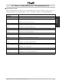
Table 1 Terminator Switch Functions and Modbus RTU
Switch
Setting
Switches 2 & 3 Used for terminating an RS-485 interface. On first and last devices in a multiple device
network, or on the only device in a single device network, switches 2 and 3 must be ON.
On all other devices in a multiple device network, 2 and 3 must be OFF.
The Modbus RTU communication cable must be
kept away from motor and brake resistor cables to
avoid coupling of high frequency noise from one
cable to the other. Normally a distance of 200 mm (8
inches) is sufficient, but it is generally recommended
to keep the greatest possible distance between the
cables, especially where cables run in parallel over
long distances. If the Modbus RTU cable has to
cross a motor and brake resistor cable they must
cross each other at an angle of 90 degrees.
9
VLT® 2800, VLT® 6000 HVAC and VLT® 8000 AQUA Modbus RTU
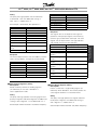
■ VLT 2800 Parameter Settings for Modbus
Communication
Using the Modbus RTU Protocol requires setting
of the below listed parameters.
Description of choice:
The frequency converter’s transmission speed
must be set at a value corresponding to the
transmission speed of the master.
Parameter 501 Baudrate cannot be selected via the
serial port, but must be preset via the operating unit.
NB!:
Please make sure that par. 512 Telegram
Profile is set to FC PROFILE.
561 Protocol
(PROTOCOL)
See the VLT 2800 Operating Instructions
MG.28.AX.YY for details on selecting and changing
parameter values, if necessary.
Value:
✭FC protocol (FC PROTOCOL)
Metasys N2 (METASYS N2)
MODBUS RTU (MODBUS RTU)
500 Address
(BUS ADDRESS)
Value:
Parameter 500 Protocol = FC protocol [0]
0 - 247
Parameter 500 Protocol = Metasys N2 [1]
1 - 255
Parameter 500 Protocol = MODBUS RTU [3]
1 - 247
[1]
[2]
[3]
Function:
There is a choice of three different protocols.
✭ 1
Description of choice:
Select the required control word protocol.
✭ 1
✭ 1
570 Modbus parity and message framing
(M.BUS PAR./FRAME)
Function:
This parameter allows the allocation of an
address to each frequency converter in a serial
communication network.
Value:
(EVEN/1 STOPBIT)
(ODD/1 STOPBIT)
✭ (NO PARITY/1 STOPBIT)
(NO PARITY/2 STOPBIT)
Description of choice:
The individual frequency converter must be
allocated a unique address.
If the number of units connected (frequency converters
+ master) is higher than 31, a repeater must be used.
Parameter 500 Address cannot be selected via the serial
communication, but must be preset via the control unit.
[0]
[1]
[2]
[3]
Function:
This parameter sets up the drive’s Modbus RTU
interface to communicate properly with the master
controller. The parity (EVEN, ODD, or NO PARITY) must
be set to match the setting of the master controller.
Description of choice:
501 Baudrate
(BAUDRATE)
Value:
300 Baud (300 BAUD)
600 Baud (600 BAUD)
1200 Baud (1200 BAUD)
2400 Baud (2400 BAUD)
4800 Baud (4800 BAUD)
✭9600 Baud (9600 BAUD)
[0]
[1]
[2]
[3]
[4]
[5]
Select the parity that matches the setting for the
Modbus master controller. Even or odd parity is
sometimes used to allow a transmitted word to be
checked for errors. Because Modbus RTU uses
the more efficient CRC (Cyclic Redundancy Check)
method of checking for errors, parity checking is
seldom used in Modbus RTU networks.
Function:
This parameter is for programming the speed at which
data is transmitted via the serial port. Baud rate is
defined as the number of bits transmitted per second.
✭ = factory setting. () = display text [] = value for use in communication via serial communication port
10
MG.10.S2.02 - VLT is a registered Danfoss trademark
VLT® 2800, VLT® 6000 HVAC and VLT® 8000 AQUA Modbus RTU
571
Modbus communications timeout
(M.BUS COM.TIME.)
Value:
10 ms - 2000 ms
✭ 100 ms
Function:
This parameter determines the maximum amount
of time that the drive’s Modbus RTU will wait
between characters that are sent by the master
controller. When this amount of time expires, the
drive’s Modbus RTU interface will assume that it
has received the entire message.
Description of choice:
Modbus RTU
Programming
Generally, the value of 100 ms is sufficient for Modbus
RTU networks, although some Modbus RTU networks
may operate on a time-out value as short as 35 ms.
If this value is set too short, the drive’s Modbus RTU
interface may miss a part of the message. Since the
CRC check will not be valid, the drive will ignore the
message. The resulting retransmissions of messages
will slow communications on the network.
If this value is set too long, the drive will wait longer
than necessary to determine that the message is
completed. This will delay the drive’s response to the
message and possibly cause the master controller to
time out. The resulting retransmissions of messages
will slow communications on the network.
✭ = factory setting. () = display text [] = value for use in communication via serial communication port
MG.10.S2.02 - VLT is a registered Danfoss trademark
11
VLT® 2800, VLT® 6000 HVAC and VLT® 8000 AQUA Modbus RTU
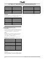
■ VLT 6000 Parameter Settings for Modbus
Communication
Using the Modbus RTU Protocol requires setting
of the below listed parameters.
See the VLT 6000 Operating Instructions
MG.61.AX.YY for details on selecting and changing
parameter values, if necessary.
500
570 Modbus parity and message framing
(M.BUS PAR./FRAME)
Value:
(EVEN/1 STOPBIT)
(ODD/1 STOPBIT)
✭ (NO PARITY/1 STOPBIT)
(NO PARITY/2 STOPBIT)
Protocol
(PROTOCOL)
Value:
✭FC protocol (FC PROTOCOL)
Metasys N2 (METASYS N2)
Landis/Staefa Apogee FLN (LS FLN)
Modbus RTU (MODBUS RTU)
[0]
[1]
[2]
[3]
Function:
There is a choice of four different protocols.
Description of choice:
Select the required control word protocol.
Function:
This parameter sets up the drive’s Modbus RTU
interface to communicate properly with the master
controller. The parity (EVEN, ODD, or NO PARITY) must
be set to match the setting of the master controller.
Description of choice:
Select the parity that matches the setting for the
Modbus master controller. Even or odd parity is
sometimes used to allow a transmitted word to be
checked for errors. Because Modbus RTU uses
the more efficient CRC (Cyclic Redundancy Check)
method of checking for errors, parity checking is
seldom used in Modbus RTU networks.
501 Address
(ADDRESS)
571
Value:
Parameter
0 - 126
Parameter
1 - 255
Parameter
0 - 98
Parameter
1 - 247
Value:
10 ms - 2000 ms
500 Protocol = FC protocol [0]
✭ 1
500 Protocol = Metasys N2 [1]
✭ 1
500 Protocol = LS FLN [2]
✭ 1
500 Protocol = MODBUS RTU [3]
Function:
In this parameter it is possible to allocate an
address in a serial communication network to
each frequency converter.
Description of choice:
The individual frequency converter must be
given a unique address.
If the number of units connected (frequency
converters + master) exceeds 31, an amplifier
(repeater) must be used. Parameter 501 Address
cannot be chosen via serial communication, but
must be set via the LCP control unit.
✭ 1
[0]
[1]
[2]
[3]
Modbus communications timeout
(M.BUS COM.TIME.)
✭ 100 ms
Function:
This parameter determines the maximum amount
of time that the drive’s Modbus RTU will wait
between characters that are sent by the master
controller. When this amount of time expires, the
drive’s Modbus RTU interface will assume that it
has received the entire message.
Description of choice:
Generally, the value of 100 ms is sufficient for Modbus
RTU networks, although some Modbus RTU networks
may operate on a time-out value as short as 35 ms.
If this value is set too short, the drive’s Modbus RTU
interface may miss a part of the message. Since the
CRC check will not be valid, the drive will ignore the
message. The resulting retransmissions of messages
will slow communications on the network.
If this value is set too long, the drive will wait longer
than necessary to determine that the message is
completed. This will delay the drive’s response to the
message and possibly cause the master controller to
time out. The resulting retransmissions of messages
will slow communications on the network.
✭ = factory setting. () = display text [] = value for use in communication via serial communication port
12
MG.10.S2.02 - VLT is a registered Danfoss trademark
VLT® 2800, VLT® 6000 HVAC and VLT® 8000 AQUA Modbus RTU
■ VLT 8000 Parameter Settings for Modbus
Communication
Using the Modbus RTU Protocol requires setting
of the below listed parameters.
See the VLT 8000 Operating Instructions
MG.80.AX.YY for details on selecting and changing
parameter values, if necessary.
Description of choice:
Protocol
(PROTOCOL)
Value:
✭FC protocol (FC PROTOCOL)
Modbus RTU (MODBUS RTU)
[0]
[1]
Function:
There is a choice of two different protocols.
571
Description of choice:
Modbus communications timeout
(M.BUS COM.TIME.)
Value:
10 ms - 2000 ms
Select the required control word protocol.
501 Address
(ADDRESS)
Value:
Parameter 500 Protocol = FC protocol [0]
0 - 126
Parameter 500 Protocol = MODBUS RTU [1]
1 - 247
Select the parity that matches the setting for the
Modbus master controller. Even or odd parity is
sometimes used to allow a transmitted word to be
checked for errors. Because Modbus RTU uses
the more efficient CRC (Cyclic Redundancy Check)
method of checking for errors, parity checking is
seldom used in Modbus RTU networks.
✭ 1
✭ 1
✭ 100 ms
Function:
This parameter determines the maximum amount
of time that the drive’s Modbus RTU will wait
between characters that are sent by the master
controller. When this amount of time expires, the
drive’s Modbus RTU interface will assume that it
has received the entire message.
Description of choice:
Generally, the value of 100 ms is sufficient for Modbus
RTU networks, although some Modbus RTU networks
may operate on a time-out value as short as 35 ms.
If this value is set too short, the drive’s Modbus RTU
interface may miss a part of the message. Since the
CRC check will not be valid, the drive will ignore the
message. The resulting retransmissions of messages
will slow communications on the network.
If this value is set too long, the drive will wait longer
than necessary to determine that the message is
completed. This will delay the drive’s response to the
message and possibly cause the master controller to
time out. The resulting retransmissions of messages
will slow communications on the network.
Function:
In this parameter it is possible to allocate an
address in a serial communication network to
each frequency converter.
Description of choice:
The individual frequency converter must be
given a unique address.
If the number of units connected (frequency
converters + master) exceeds 31, an amplifier
(repeater) must be used. Parameter 501 Address
cannot be chosen via serial communication, but
must be set via the LCP control unit.
570 Modbus parity and message framing
(M.BUS PAR./FRAME)
Value:
(EVEN/1 STOPBIT)
(ODD/1 STOPBIT)
✭ (NO PARITY/1 STOPBIT)
(NO PARITY/2 STOPBIT)
[0]
[1]
[2]
[3]
✭ = factory setting. () = display text [] = value for use in communication via serial communication port
MG.10.S2.02 - VLT is a registered Danfoss trademark
13
Modbus RTU
Programming
500
Function:
This parameter sets up the drive’s Modbus RTU
interface to communicate properly with the master
controller. The parity (EVEN, ODD, or NO PARITY) must
be set to match the setting of the master controller.
VLT® 2800, VLT® 6000 HVAC and VLT® 8000 AQUA Modbus RTU
■ Network
Configuration
■ Remote Terminal Unit
The controllers are setup to communicate on the
Modbus network using RTU (Remote Terminal
Unit) mode, with each 8-bit byte in a message
contains two 4-bit hexadecimal characters. The
format for each byte is shown below.
Coding System:
8-bit binary, hexadecimal 0-9, A-F
Two hexadecimal characters contained in
each 8-bit field of the message
Bits Per Byte:
1 start bit
8 data bits, least significant bit sent first
1 bit for even/odd parity; no bit for no parity
1 stop bit if parity is used; 2 bits if no parity
Error Check Field:
Start bit
Data bit
Cyclical Redundancy Check (CRC)
Stop/
Stop
parity
■ Modbus RTU Message Framing Structure
A Modbus RTU message is placed by the transmitting
device into a frame with a known beginning and
ending point. This allows receiving devices to begin
at the start of the message, read the address portion,
determine which device is addressed (or all devices,
if the message is broadcast), and to know when
the message is completed. Partial messages are
detected and errors set as a result.
monitor the network bus continuously, including ‘silent’
intervals. When the first field (the address field) is
received, each frequency converter or device decodes
it to determine whether it is the addressed device.
Modbus RTU messages addressed to zero are
broadcast messages. No response is permitted
on broadcast messages.
A typical message frame is shown below.
The allowable characters transmitted for all fields
are hexadecimal 00 to FF. The frequency converter
Start
T1-T2-T3-T4
Address
8 Bits
Function
Data
CRC Check
8 Bits
n x 8 bits
16 Bits
Typical Modbus RTU Message Structure
■ Start/Stop Field
Messages start with a silent interval of at least 3.5
character times. This is implemented as a multiple of
character times at the selected network baud rate
(shown as Start T1-T2-T3-T4). The first field then
transmitted is the device address. Following the last
transmitted character, a similar interval of at least 3.5
character times marks the end of the message. A
new message can begin after this interval.
End
T1-T2-T3-T4
message and assumes that the next byte will be
the address field of a new message.
Similarly, if a new message begins earlier that 3.5
character times following a previous message, the
receiving device will consider it a continuation of the
previous message. This will cause a time-out (no
response from the slave), since the value in the final
CRC field is not valid for the combined messages.
The entire message frame must be transmitted as a
continuous stream. If a silent interval of more than
1.5 character times occurs before completion of the
frame, the receiving device flushes the incomplete
14
MG.10.S2.02 - VLT is a registered Danfoss trademark
VLT® 2800, VLT® 6000 HVAC and VLT® 8000 AQUA Modbus RTU
■ Address Field
The address field of a message frame contains 8 bits.
Valid slave device addresses are in the range of 0 –
247 decimal. The individual slave devices are assigned
addresses in the range of 1 – 247. (0 is reserved for
broadcast mode, which all slaves recognize.) A master
addresses a slave by placing the slave address in the
address field of the message. When the slave sends its
response, it places its own address in this address field
to let the master know which slave is responding.
appends the CRC as the last field in the message. The
receiving device recalculates a CRC during receipt of
the message and compares the calculated value to
the actual value received in the CRC field. If the two
values are not equal, a bus time-out results.
The error checking field contains a 16-bit binary
value implemented as two 8-bit bytes. When this is
done, the low-order byte of the field is appended first,
followed by the high-order byte. The CRC high-order
byte is the last byte sent in the message.
■ Function Field
■ Coil/Register Addressing
The function field of a message frame contains 8 bits.
All data addresses in Modbus messages are referenced
Valid codes are in the range of 1-FF. (See section
to zero. The first occurrence of a data item is
Modbus RTU Function Codes.) When a message is
addressed as item number zero. For example:
sent from a master to a slave device, the function code
field tells the slave what kind of action to perform.
The coil known as ‘coil 1’ in a programmable controller
is addressed as coil 0000 in the data address
When the slave responds to the master, it uses the
field of a Modbus message. Coil 127 decimal is
function code field to indicate either a normal (error-free)
addressed as coil 007EHEX (126 decimal).
response, or that some kind of error occurred (called
an exception response). For a normal response, the
slave simply echoes the original function code. For
an exception response, the slave returns a code
that is equivalent to the original function code with
its most-significant bit set to a logic 1. In addition,
the slave places a unique code into the data field
of the response message. This tells the master
what kind of error occurred, or the reason for the
exception. See the chapter Exception Codes in
these operating instructions for definitions.
Holding register 40001 is addressed as register
0000 in the data address field of the message.
The function code field already specifies a ‘holding
register’ operation. Therefore, the ‘4XXXX’ reference
is implicit. Holding register 40108 is addressed
as register 006BHEX (107 decimal).
Network
Configuration
■ Data Field
The data field is constructed using sets of two
hexadecimal digits, in the range of 00 to FF
hexadecimal. These are made from one RTU character.
The data field of messages sent from a master to slave
device contains additional information which the slave
must use to take the action defined by the function
code. This can include items like coil or register
addresses, the quantity of items to be handled, and
the count of actual data bytes in the field.
■ CRC Check Field
Messages include an error-checking field that is based
on a cyclical redundancy check (CRC) method. The
CRC field checks the contents of the entire message. It
is applied regardless of any parity check method used
for the individual characters of the message. The CRC
value is calculated by the transmitting device, which
MG.10.S2.02 - VLT is a registered Danfoss trademark
15
VLT® 2800, VLT® 6000 HVAC and VLT® 8000 AQUA Modbus RTU
■ Parameter
Handling
■ Parameter Handling
PNU (Parameter Number) is translated from the
register address contained in the Modbus read/write
message. The parameter number is translated to
Modbus as (10 x parameter number)DECIMAL.
■ Storage of Data
Coil 65 decimal determines whether data written to
the frequency converter are stored in EEPROM and
RAM (coil 65 = 1) or just RAM (coil 65 = 0).
■ IND
Array index is set in Holding Register 9 and used
when accessing array parameters in the frequency
converter such as parameter 606-617 (Logs).
■ Text Blocks
Parameters stored as text strings are accessed in the
same way as the other parameters. The maximum
text block size is 20 characters. If a read request for a
parameter is for more characters than the parameter
stores, the response is space filled. If the read
request for a parameter is for less characters than the
parameter stores, the response is truncated.
Index
74
2
1
0
-1
-2
-3
-4
Factor
3.6
100.0
10.0
1.0
0.1
0.01
0.001
0.0001
■ Parameter Values
Standard Data Types
Standard data types are int16, int32, uint8, uint16
and uint32. They are stored as 4x registers (40001 –
4FFFF). The parameters are read using function 03HEX
"Read Holding Registers." Parameters are written using
function 6HEX "Preset Single Register" for 1 register (16
bits), and function 10HEX "Preset Multiple Registers" for
2 registers (32 bits). Valid sizes to read are 1 register
(16 bits) and through 10 registers (20 characters).
Nonstandard Data Types
Nonstandard data types are text strings and are stored
as 4x registers (40001 – 4FFFF). The parameters are
read using function 03HEX "Read Holding Registers"
and written using function 10HEX "Preset Multiple
Registers." Valid sizes to read are 1 register (2
characters) through 10 registers (20 characters).
■ PCD1 / PCD2
PCD contains the process word block. The parameter
value block consists of 2 words (4 bytes). The process
word block is divided into two blocks of 16 bits and
is stored in Modbus as status coils. The mapping
of the PCD is shown in the table below.
■ Conversion Factor
The different attributes for each parameter can be seen
in the section on factory settings. Since a parameter
value can only be transferred as a whole number, a
conversion factor must be used to transfer decimals.
Parameter 201: Minimum Frequency, conversion
factor 0.1. If parameter 201 is to be set to 10
Hz, a value of 100 must be transferred, since a
conversion factor of 0.1 means that the transferred
value will be multiplied by 0.1. A value of 100 will,
therefore, be understood as 10.0.
16
MG.10.S2.02 - VLT is a registered Danfoss trademark
VLT® 2800, VLT® 6000 HVAC and VLT® 8000 AQUA Modbus RTU
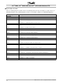
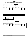
■ Register Maps VLT 2800
Note: the Holding Register number shown in the following table must be transmitted as ("shown value-1") in
MODBUS telegrams (e.g. Holding Register 4:00001 is transmitted as address 0 in MODBUS telegrams).
Description
Reserved
Array index (1-255)
Parameter 001, Language
↓
Parameter 025, Quick Menu Setup
Reserved
Parameter 100, Configuration
↓
Parameter 146, Reset Voltage Vector
Reserved
Parameter 200, Output Frequency Range
↓
Parameter 231, Frequency Bypass 2
Reserved
Parameter 302, Digital Input, Terminal 18
↓
Parameter 349, Speed Compensation Delay
Reserved
Parameter 400, Reset Function
↓
Parameter 456, Brake Voltage Reduce
Reserved
Parameter 500, Protocol
↓
Parameter 544, Pulse Count
Reserved
Parameter 600, Operating Data: Operating Hours
↓
Parameter 642, Power Card Identification
Reserved
MG.10.S2.02 - VLT is a registered Danfoss trademark
Parameter
Handling
Holding Register
(decimal)
00001-00008
00009
00010
↓
00250
00260-00999
01000
↓
01460
01470-1999
02000
↓
02310
02320-02999
03020
↓
03490
03500-03999
04000
↓
04560
04570-04999
05000
↓
05440
05450-05999
06000
↓
06420
06430-65536
17
VLT® 2800, VLT® 6000 HVAC and VLT® 8000 AQUA Modbus RTU
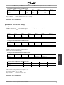
■ Register Maps VLT 6000
Note: the Holding Register number shown in the following table must be transmitted as ("shown value-1") in
MODBUS telegrams (e.g. Holding Register 4:00001 is transmitted as address 0 in MODBUS telegrams).
Holding Register
(decimal)
00001-00008
00009
00010
↓
00170
00180-00999
01000
↓
01180
01190-1999
02000
↓
02280
02290-02999
03000
↓
03650
03660-03999
04000
↓
04830
04840-04999
05000
↓
05710
05720-05999
06000
↓
06310
06320-06999
07000
↓
07110
07120-65536
18
Description
Reserved
Array index (1-255)
Parameter 001, Language
↓
Parameter 017, Operating State at Power-up
Reserved
Parameter 100, Configuration
↓
Parameter 118, Motor Power Factor
Reserved
Parameter 200, Output Frequency Range
↓
Parameter 228, Warning: High Feedback
Reserved
Parameter 300, Terminal 16 Digital Input
↓
Parameter 365, Terminal 45, Bus Control
Reserved
Parameter 400, Reset Function
↓
Parameter 483, Dynamic DC Link Compensation
Reserved
Parameter 500, Protocol
↓
Parameter 571, Modbus Communications Timeout
Reserved
Parameter 600, Operating Data: Operating Hours
↓
Parameter 631, Nameplate: Communication Option Ordering No.
Reserved
Parameter 700, Relay 6, Output Function
↓
Parameter 711, Relay 9, Off Delay
Reserved
MG.10.S2.02 - VLT is a registered Danfoss trademark
VLT® 2800, VLT® 6000 HVAC and VLT® 8000 AQUA Modbus RTU
■ Register Maps VLT 8000
Note: the Holding Register number shown in the following table must be transmitted as ("shown value-1") in
MODBUS telegrams (e.g. Holding Register 4:00001 is transmitted as address 0 in MODBUS telegrams).
Description
Reserved
Array index (1-255)
Parameter 001, Language
↓
Parameter 017, Operating State at Power-up
Reserved
Parameter 100, Configuration
↓
Parameter 124, Stator Reactance
Reserved
Parameter 200, Output Frequency Range
↓
Parameter 231, Filled Set Point
Reserved
Parameter 300, Terminal 16 Digital Input
↓
Parameter 365, Terminal 45, Bus Control
Reserved
Parameter 400, Reset Function
↓
Parameter 483, Dynamic DC Link Compensation
Reserved
Parameter 500, Protocol
↓
Parameter 571, Modbus Communications Timeout
Reserved
Parameter 600, Operating Data: Operating Hours
↓
Parameter 631, Nameplate: Communication Option Ordering No.
Reserved
Parameter 700, Relay 6, Output Function
↓
Parameter 711, Relay 9, Off Delay
Reserved
MG.10.S2.02 - VLT is a registered Danfoss trademark
Parameter
Handling
Holding Register
(decimal)
00001-00008
00009
00010
↓
00170
00180-00999
01000
↓
01240
01250-1999
02000
↓
02310
02320-02999
03000
↓
03650
03660-03999
04000
↓
04830
04840-04999
05000
↓
05710
05720-05999
06000
↓
06310
06320-06999
07000
↓
07110
07120-65536
19
VLT® 2800, VLT® 6000 HVAC and VLT® 8000 AQUA Modbus RTU
■ Process Data
Process Data is illustrated as coils in Modbus RTU.
■ Status Coil Maps
(128 coils total)
Note: The coil number shown in the following table
must be transmitted as ("shown value-1") in MODBUS
telegrams (e.g. Coil number 0:00001 is transmitted
as address 0000 in the MODBUS telegram).
Coil
Number
1-16
17-32
33-48
49-64
65
66-128
■ Control Word Bit Descriptions for VLT 2800
The control word is used to send commands from a
master (e.g. a PC) to a slave (frequency converter).
Bit
00
01
02
03
04
05
06
07
08
09
10
11
12
13
14
15
Bit = 0
DC braking
Coasting stop
Quick stop
Freeze outp. freq.
Ramp stop
Ramp 1
Data not valid
No function
No function
Bit =1
Preset ref. lsb
Preset ref. msb
Start
Reset
Jog
Ramp 2
Data valid
Relay 01 activated
Digital output
Terminal 46
activated
Select Setup, lsb
Select Setup, msb
Reversing
Preset ref.
1
2
3
4
Description
PCD1 Control Word (master → slave)
PCD2 Reference Value (master →
slave)
PCD1 Status Word (slave → master)
PCD2 Given output frequency (slave
→ master)
Write parameters to eeprom (1 = true
/ 0 = false)
Reserved
Parameter
215
216
217
218
Bit 01
0
0
1
1
Bit 00
0
1
0
1
NB!:
In parameter 508 Selection of preset
reference a selection is made to define how
Bit 00/01 gates with the corresponding
function on the digital inputs.
Bit 02, DC brake:
Bit 02 = ’0’ causes DC braking and stop. Brake
voltage and duration are preset in parameters
132 DC brake voltage and parameter 126 DC
braking time. Note: In parameter 504 DC brake a
selection is made to define how Bit 02 gates with the
corresponding function on a digital input.
Bit 03, Coasting stop:
Bit 03 = ’0’ causes the frequency converter to
immediately "let go" of the motor (the output transistors
are "shut off"), so that it coasts to a standstill.
Bit 03 = ’1’ causes the frequency converter to be able
start the motor if the other starting conditions have
been fulfilled. Note: In parameter 502 Coasting stop
a selection is made to define how Bit 03 gates with
the corresponding function on a digital input.
Bit 00/01:
Bit 00/01 is used to select between the two
pre-programmed references (parameters 215-218
Preset reference) according to the following table:
20
MG.10.S2.02 - VLT is a registered Danfoss trademark
VLT® 2800, VLT® 6000 HVAC and VLT® 8000 AQUA Modbus RTU
Bit 05, Freeze output frequency:
Bit 05 = ’0’ causes the present output frequency
(in Hz) to freeze. The frozen output frequency can
now only be changed by means of the digital inputs
programmed to Speed up and Speed down.
NB!:
If Freeze output is active, the frequency
converter cannot be stopped via Bit 06 Start
or via a digital input. The frequency converter
can only be stopped by the following:
• Bit 03 Coasting stop
• Bit 02 DC braking
• Digital input programmed to DC braking, Coasting
stop or Reset and coasting stop.
Bit 06, Ramp stop/start:
Bit 06 = ’0’ causes a stop, in which the motor’s
speed is ramped down to stop via the selected
ramp down parameter.
Bit 06 = ’1’ causes the frequency converter to be able
to start the motor, if the other starting conditions have
been fulfilled. Note: In parameter 505 Start a selection
is made to define how Bit 06 Ramp stop/start gates
with the corresponding function on a digital input.
Bit 07, Reset:
Bit 07 = ’0’ does not cause a reset.
Bit 07 = ’1’ causes the reset of a trip. Reset is
activated on the signal’s leading edge, i.e. when
changing from logic ’0’ to logic ’1’.
Bit 11, Relay 01:
Bit 11 = "0" Relay not activated.
Bit 11 = "1" Relay 01 activated, provided Control
word bit has been chosen in parameter 323.
Bit 12, Digital output, terminal 46:
Bit 12 = "0" Digital output has not been activated.
Bit 12 = "1" Digital output has been activated, provided
Control word bit has been chosen in parameter 341.
Bit 13/14, Selection of Setup:
Bits 13 and 14 are used to choose from the four menu
Setups according to the following table:
Setup
1
2
3
4
Bit 14
0
0
1
1
Bit 13
0
1
0
1
The function is only possible when Multi-Setups is
selected in parameter 004 Active Setup .
Note: I parameter 507 Selection of Setup a selection
is made to define how Bit 13/14 gates with the
corresponding function on the digital inputs.
Bit 15 Reversing:
Bit 15 = ’0’ causes no reversing.
Bit 15 = ’1’ causes reversing.
Note: In the factory setting reversing is set to
digital in parameter 506 Reversing. Bit 15 only
causes reversing when either Ser. communication,
Logic or or Logic and is selected.
■ Status Word Bit Description for VLT 2800
Bit 08, Jog:
Bit 08 = ’1’ causes the output frequency to be
determined by parameter 213 Jog frequency.
Bit 09, Selection of ramp 1/2:
Bit 09 = "0" means that ramp 1 is active (parameters
207/208). Bit 09 = "1" means that ramp 2
(parameters 209/210) is active.
Bit 10, Data not valid/Data valid:
Is used to tell the frequency converter whether the
control word is to be used or ignored. Bit 10 = ’0’
causes the control word to be ignored, Bit 10 = ’1’
causes the control word to be used. This function
is relevant, because the control word is always
contained in the telegram, regardless of which type
of telegram is used, i.e. it is possible to turn off the
control word if you do not wish to use it in connection
with updating or reading parameters.
MG.10.S2.02 - VLT is a registered Danfoss trademark
The status word is used to inform the master
(e.g. a PC) of the slave’s (frequency converter)
mode. Slave⇒Master.
21
Parameter
Handling
Bit 04, Quick stop:
Bit 04 = ’0’ causes a stop, in which the motor’s
speed is ramped down to stop via parameter
212 Quick stop ramp-down time.
VLT® 2800, VLT® 6000 HVAC and VLT® 8000 AQUA Modbus RTU
Bit
00
01
02
03
04
05
06
07
08
09
10
11
12
13
14
15
Bit = 0
Bit =1
Control ready
Drive ready
Coasting stop
No trip
Not used
Not used
No warning
Speed ≠ ref.
Local control
Outside
frequency range
Trip
Trip lock
Warning
Speed = ref.
Ser. communi.
Frequency limit
OK
Motor running
Voltage warn.
Current limit
Thermal warn.
Bit 00, Control ready:
Bit 00 = ’1’. The frequency converter is
ready for operation.
Bit 00 = ’0’. The frequency converter is not
ready for operation.
Bit 01, Drive ready:
Bit 01 = ’1’. The frequency converter is ready for
operation, but there is an active coasting command
via the digital inputs or via serial communication.
Bit 02, Coasting stop:
Bit 02 = ’0’. The frequency converter has
released the motor.
Bit 02 = ’1’. The frequency converter can start the
motor when a start command is given.
Bit 03, No trip/trip:
Bit 03 = ’0’ means that the frequency converter
is not in fault mode.
Bit 03 = ’1’ means that the frequency converter
is tripped, and that it needs a reset signal for
operation to be re-established.
Bit 04, Not used:
Bit 04 is not used in the status word.
Bit 05, Not used:
Bit 05 is not used in the status word.
Bit 06, Trip lock:
Bit 06 = ’0’ means that the frequency converter
is not trip locked.
Bit 06 = ’1’ means that the frequency converter
is trip locked and it cannot be reset before the
mains supply has been removed. The trip can be
reset either with 24 V external control back up or
after the power is connected again.
22
Bit 07, No warning/warning:
Bit 07 = ’0’ means that there are no warnings.
Bit 07 = ’1’ means that a warning has occurred.
Bit 08, Speed≠ ref/speed = ref.:
Bit 08 = ’0’ means that the motor is running, but that
the present speed is different from the preset speed
reference. It might, for example, be the case while the
speed is being ramped up/down during start/stop.
Bit 08 = ’1’ means that the motor’s present speed
is the same as the preset speed reference.
Bit 09, Local operation/serial communication control:
Bit 09 = ’0’ means that [STOP/RESET] is activated
on the control unit, or that Local control in parameter
002 Local/remote operation is selected. It is
not possible to control the frequency converter
via serial communication.
Bit 09 = ’1’ means that it is possible to control the
frequency converter via serial communication.
Bit 10, Outside frequency range:
Bit 10 = ’0’, if the output frequency has reached
the value in parameter 201 Output frequency
low limit or parameter 202 Output frequency
high limit. Bit 10 = "1" means that the output
frequency is within the defined limits.
Bit 11, Running/not running:
Bit 11 = ’0’ means that the motor is not running.
Bit 11 = ’1’ means that the frequency converter
has a start signal or that the output frequency
is greater than 0 Hz.
Bit 13, Voltage warning high/low:
Bit 13 = ’0’ means that there are no voltage warnings.
Bit 13 = ’1’ means that the DC voltage in the frequency
converter’s intermediate circuit is too low or too high.
Bit 14, Current limit:
Bit 14 = ’0’ means that the output current is less than
the value in parameter 221 Current Limit ILIM.
Bit 14 = ’1’ means that the output current is greater than
the value in parameter 221 Current Limit ILIM and that
the frequency converter will trip after a set period of time.
Bit 15, Thermal warning:
Bit 15 = ’0’ means that there is no thermal warning.
Bit 15 = ’1’ means that the temperature limit has been
exceeded in either the motor, frequency converter or
from a thermistor that is connected to a digital input.
MG.10.S2.02 - VLT is a registered Danfoss trademark
VLT® 2800, VLT® 6000 HVAC and VLT® 8000 AQUA Modbus RTU
■ Present output frequency
The serial communication reference is transferred to
the frequency converter as a 16-bit word. The value is
transferred in whole numbers 0 - ±32767 (±200%).
16384 (4000 Hex) corresponds to 100%.
The value of the frequency converter’s present output
frequency is transferred as a 16-bit word. The value is
transferred as whole numbers 0 - ±32767 (±200%).
16384 (4000 Hex) corresponds to 100%.
The serial communication reference has the following
format: 0-16384 (4000 Hex) 0-100% (Par. 204
Minimum ref. - Par. 205 Maximum ref.).
Output frequency has the following format:
0-100% (Par. 201
0-16384 (4000 Hex)
Output frequency low limit - Par. 202 Output
frequency high limit).
It is possible to change the direction of rotation via the
serial reference. This is done by converting the binary
reference value to 2’ complement. See example.
Example - Control word and serial communication ref.:
The frequency converter is to receive a start
command and the reference is to be set to 50%
(2000 Hex) of the reference range.
Control word = 047F Hex ⇒ Start command.
Reference = 2000 Hex ⇒ 50% reference.
The frequency converter is to receive a start
command and the reference is to be set to -50%
(-2000 Hex) of the reference range.
The reference value is first converted to 1’ complement,
and then 1 is added binarily to obtain 2’ complement:
2000 Hex
1’ complement
2’ complement
0010 0000 0000 0000 0000
1101 1111 1111 1111 1111
+ 1
1110 0000 0000 0000 0000
Example - Status word and current output frequency:
The master receives a status message from the
frequency converter that the current output frequency
is 50% of the output frequency range.
Par. 201 Output frequency low limit = 0 Hz
Par. 202 Output frequency high limit = 50 Hz
Status word = 0F03 Hex.
Output frequency = 2000 Hex ⇒ 50% of the frequency
range, corresponding to 25 Hz.
■ Control Word Bit Descriptions VLT 6000 / VLT 8000
The control word is used for transmitting commands
from a master (e.g. a PC) to a slave.
Control word = 047F Hex ⇒ Start command.
Reference = E000 Hex ⇒ -50% reference.
MG.10.S2.02 - VLT is a registered Danfoss trademark
23
Parameter
Handling
■ Serial communication reference
VLT® 2800, VLT® 6000 HVAC and VLT® 8000 AQUA Modbus RTU
Bit
00
01
02
03
04
05
06
07
08
09
10
11
12
13
14
15
Bit = 0
Bit =1
Preset ref. lsb
Preset ref. msb
DC braking
Coasting stop
Quick stop
Freeze output frequency
Ramp stop
Start
Reset
Jog
No function
No function
Data not valid
Data valid
Activate relay 1
Activate relay 2
Choice of setup lsb
Choice of setup msb
Reversing
Bit 00/01:
Bits 00 and 01 are used for choosing between the four
pre-programmed references (parameters 211- 214
Preset reference) in accordance with the following table:
Preset ref.
1
2
3
4
Parameter
211
212
213
214
Bit 01
0
0
1
1
Bit 00
0
1
0
1
Bit 05 = "0" means that the given output frequency (in
Hz) is frozen. The frozen output frequency can now
only be changed via the digital inputs programmed
for Speed up and Speed down.
NB!:
If Freeze output is active, the frequency
converter cannot be stopped via Bit 06 Start
or via terminal 18. The frequency converter
can only be stopped in the following ways:
•
•
•
•
Bit 03 Coasting stop
Terminal 27
Bit 02 DC braking
Terminal 19 programmed for DC braking
Bit 06, Ramp stop/start:
wBit 04 = "0" leads to a stop in which the motor
speed is ramped down to stop via parameter
207 Ramp-down time.
Bit 06 = "1" means that the frequency converter is able
to start the motor, provided the other conditions for
starting are fulfilled. Note: In parameter 505 Start a
choice is made of the way bit 06 Ramp stop/start is to
be gated with the corresponding function of terminal 18.
NB!:
Parameter 508 Choice of preset reference
is used to choose how bits 00/01 are
to be gated with the corresponding
functions of the digital inputs.
Bit 07, Reset:
Bit 07 = "0" leads to no reset.
Bit 07 = "1" means that a trip is reset.
Reset is activated on the leading edge of the signal,
i.e. at the change from logic ’0’ to logic ’1’.
Bit 02, DC BRAKE:
Bit 02 = 0 leads to DC braking and stop. Set
braking current and duration in parameter 114 DC
braking current and in parameter 115 DC braking
time. Note: Parameter 504 DC brake is used
for selecting how bit 02 is to be gated with the
corresponding function of terminal 27.
Bit 08, Jog:
Bit 08 = "1" means that the output frequency is
determined by parameter 209 Jog frequency.
Bit 03, Coasting stop:
Bit 03 = "0" means that the frequency converter
immediately "lets go" of the motor (the output
transistors are "turned off"), which means that
the motor runs freely until it stops.
Bit 03 = "1" means that the frequency converter is able
to start the motor, provided the other conditions for
starting are fulfilled. Note: In parameter 503 Coasting
stop the choice is made of how bit 03 is to be gated
with the corresponding function of terminal 27.
Bit 04, Quick stop:
Bit 04 = "0" leads to a stop in which the motor
speed is ramped down to stop via parameter
207 Ramp-down time.
Bit 05, Freeze output frequency:
24
Bit 09, No function:
Bit 09 has no function.
Bit 10, Data not valid/Data valid:
Used for telling the frequency converter whether the
control is to be used or ignored. Bit 10 = "0" means that
the control word is ignored. Bit 10 = "1" means that the
control word is used. This function is relevant because
the control word is always contained in the telegram,
regardless of the type of telegram used, i.e. it is possible
to disconnect the control word if it is not to be used in
connection with updating or reading of parameters.
Bit 11, Relay 1:
Bit 11 = "0": Relay 1 is not activated.
Bit 11 = "1": Relay 1 is activated, provided
Control word bits 11/12 has been selected in
parameter 323 Relay outputs.
Bit 12, Relay 2:
Bit 12 = "0": Relay 2 is not activated.
MG.10.S2.02 - VLT is a registered Danfoss trademark
VLT® 2800, VLT® 6000 HVAC and VLT® 8000 AQUA Modbus RTU
NB!:
If the time-out period set in parameter 556
Bus time interval function is exceeded, relays
1 and 2 will lose their voltage if they have
been activated via serial communication.
Bits 13/14, Choice of Setup:
Bits 13 and 14 are used to choose among the four
menu Setups in accordance with the following table:
Setup
1
2
3
4
Bit 14
0
0
1
1
Bit 13
0
1
0
1
This function is only possible if Multi-setups has
been selected in parameter 004.
Note: In parameter 507 Choice of Setup a choice is
made of the way bits 13/14 are to be gated with the
corresponding function of the digital inputs.
Bit 15, No function/reversing:
Bit 15 = "0" leads to no reversing.
Bit 15 = "1" leads to reversing.
Please note that, in the factory setting, reversing has
been selected as digital in parameter 506 Reversing,
which means that bit 15 only leads to reversing, if
bus, logic or orlogic and has been selected (however,
logic and only together with terminal 19).
■ Status Word Bit Descriptions VLT 6000 / VLT 8000
The status word is used to inform the master
(e.g. a PC) of the condition of the slave (VLT
6000 HVAC / VLT 8000 AQUA).
Bit
00
01
02
03
04
05
06
07
08
09
10
11
12
13
14
15
Bit = 0
Trip
No trip
Not in use
Not in use
Not in use
No warning
Speed ≠ref.
Local operation
Out of frequency range
No function
Bit = 1
Control ready
Drive ready
Stand by
Trip
Warning
Speed = ref.
Serial com. control
Parameter
Handling
Bit 12 = "1": Relay 2 is activated, provided
Control word bits 11/12 has been selected in
parameter 326 Relay outputs.
Running
No function
Voltage warning
high/low
Current limit
Thermal warning
Bit 00, Control ready:
Bit 00 = "1". The frequency converter is
ready for operation.
Bit 00 = "0". The frequency converter has tripped.
Bit 01, Drive ready:
Bit 01 = "1". The frequency converter is ready for
operation, but terminal 27 is a logic ’0’ and/or a coasting
command has been received via serial communication.
Bit 02, Stand by:
Bit 02 = "1". The frequency converter is able to start
the motor when a start command is given.
Bit 03, No trip/trip:
Bit 03 = "0" means that the VLT 6000 HVAC is not
in an error state. Bit 03 = "1" means that the VLT
6000 HVAC has tripped and needs a reset signal
in order for operation to be resumed.
Bit 04, Not in use:
Bit 04 is not used in the status word.
Bit 05, Not in use:
Bit 05 is not used in the status word.
Bit 06, Trip lock:
Bit 06: "1" means that there is a trip lock.
Bit 07, No warning/warning:
Bit 07 = "0" means there is no warning.
Bit 07 = "1" means a warning has occurred.
NB!:
All warnings are described in the Operating
Instructions.
Bit 08, Speed ≠ref./speed = ref.:
Bit 08 = "0" means that the motor is running, but
that the present speed is different from the preset
MG.10.S2.02 - VLT is a registered Danfoss trademark
25
VLT® 2800, VLT® 6000 HVAC and VLT® 8000 AQUA Modbus RTU
speed reference. This may be the case, i.e. when
the speed is ramped up/down at start/stop.
Bit 08 = "1" means that the present motor speed
equals the preset speed reference.
The serial communication reference is transmitted to
the frequency converter in the form of a 16-bit word.
The value is transmitted as whole numbers 0 - ±32767
(±200 %). 16384 (4000 Hex) corresponds to 100 %.
Bit 09, Local operation/serial communication control:
Bit 09 = "0" means that OFF/STOP has been activated
on the control unit, or that the VLT 6000 HVAC is
in Hand mode. It is not possible to control the VLT
frequency converter via serial communication.
Bit 09 = "1" means that it is possible to control the
frequency converter via serial communication.
The serial communication reference has the
following format:
Bit 10, Out of frequency range:
Bit 10 = "0" if the output frequency has reached
the value in parameter 201 Output frequency
low limit or parameter 202 Output frequency
high limit. Bit 10 = "1" means that the output
frequency is within the limits stated.
Bit 11, Not running/running:
Bit 11 = "0" means that the motor is not running.
Bit 11 = "1" means that the VLT 6000 HVAC has a start
signal, or that the output frequency is greater than 0 Hz.
0-16384 (4000 Hex) - 0-100 % (par. 204 Minimum
ref. - Par. 205 Maximum ref.).
It is possible to change the direction of rotation via
the serial reference. This is done by converting the
binary reference value to 2’s complement.
See example.
Example - control word and serial communication ref.:
The frequency converter must receive a start
command, and the reference is to be set to 50 %
(2000 Hex) of the reference range.
Control word =
Reference =
047F Hex. Start command
2000 Hex. 50 % reference
Bit 12, No function:
Bit 12 has no function.
Bit 13, Voltage warning high/low:
Bit 13 = "0" means that there is no voltage warning.
Bit 13 = "1" means that the DC voltage of the VLT 6000
HVAC intermediate circuit is too low or too high.
See the voltage limits on page 160.
Bit 14, Current limit:
Bit 14 = "0" means that the output current is smaller
than the value in parameter 215 Current limit ILIM.
Bit 14 = "1" means that the output current is higher
than the value in parameter 215 Current limit ILIM and
the frequency converter will trip after the time set in
parameter 412 Trip delay overcurrent, ILIM has passed.
The frequency converter is to receive a start
command, and the reference is to be set to -50 %
(-2000 Hex) of the reference range.
The reference value is first converted to the
first complement; then 1 binary is added to
get 2’s complement:
2000 Hex =
0010 0000 0000 0000 binary
1´ komplement =
2´ komplement =
1101 1111 1111 1111 binary
+ 1 binary
1110 0000 0000 0000 binary
Control word =
Reference =
047F Hex. Start command
E000 Hex. -50 % reference
Bit 15, Thermal warning:
Bit 15 = "0" means there is no thermal warning.
Bit 15 = "1" means that the temperature limit has been
exceeded either in the motor, in the frequency converter
or from a thermistor connected to an analogue input.
■ Serial communication reference
26
MG.10.S2.02 - VLT is a registered Danfoss trademark
VLT® 2800, VLT® 6000 HVAC and VLT® 8000 AQUA Modbus RTU
■ Present output frequency
Parameter
Handling
The value of the present output frequency of the
frequency converter at any given time is transmitted
as a 16-bit word. The value is transmitted in the form
of whole numbers 0 - ±32767 (±200 %).
16384 (4000 Hex) corresponds to 100 %.
The output frequency has the following format:
0-16384 (4000 Hex) 0-100 % (Par. 201
Output frequency low limit - Par. 202 Output
frequency high limit).
Example - Status word and present output frequency:
and present output frequency: The master receives
a status message from the frequency converter
saying that the present output frequency is 50
% of the output frequency range.
Par. 201 Output
frequency low limit =
Par. 202 Output
frequency high limit =
0 Hz
Status word =
0F03 Hex. Status
message
2000 Hex. 50 % of
the frequency range,
corresponding to 25 Hz.
Output frequency =
50 Hz
MG.10.S2.02 - VLT is a registered Danfoss trademark
27
VLT® 2800, VLT® 6000 HVAC and VLT® 8000 AQUA Modbus RTU
■ Supported Modbus RTU Function Codes
This section describes the following functions
supported by the Modbus RTU.
Read Coil Status (01HEX)
Force Single Coil (05HEX)
Force Multiple Coils (0FHEX)
■ Read Coil Status (01HEX)
Description
Reads the ON/OFF status of discrete outputs
(0X references, coils) in the slave. Broadcast
is never supported for reads.
Query
The query message specifies the starting coil and
quantity of coils to be read. Coils are addressed
starting at zero. Coils 1-16 are addressed as 0-15.
Example of a request to read coils 33-48 (Status
Word) from slave device 01.
Field Name
Slave Address
Function
Starting Address HI
Starting Address LO
No. of Points HI
No. of Points LO
Error Check (CRC)
Example (HEX)
01
01
00
20
00
10
-
Response
The coil status in the response message is packed as
one coil per bit of the data field. Status is indicated as:
1 = ON; 0 = OFF. The LSB of the first data byte contains
the coil addressed in the query. The other coils follow
toward the high order end of this byte, and from ‘low
order to high order’ in subsequent bytes. If the returned
coil quantity is not a multiple of eight, the remaining bits
in the final data byte will be padded with zeros (toward
the high order end of the byte). The Byte Count field
specifies the quantity of complete bytes of data.
Field Name
Slave Address
Function
Byte Count
Data (Coils 40-33)
Data (Coils 48-41)
Error Check (CRC)
28
Example (HEX)
01
01
02
55
AA
-
Read Holding Registers (03HEX)
Preset Single Register (06HEX)
Preset Multiple Registers (10HEX)
■ Force Single Coil (05HEX)
Description
Forces a single coil (0X reference) to either ON or
OFF. When broadcast, the function forces the same
coil references in all attached slaves.
Query
The query message specifies the coil reference
to be forced. Coils are addressed starting at
zero. Coil 1 is addressed as 0. Force Data = 00
00HEX (OFF) or FF 00HEX (ON).
See example 1 Start Motor, Run Speed 40%.
Field Name
Slave Address
Function
Coil Address HI
Coil Address LO
Force Data HI
Force Data LO
Error Check (CRC)
Example (HEX)
01
05
00
00
FF
00
-
Response
The normal response is an echo of the query, returned
after the coil state has been forced.
Field Name
Slave Address
Function
Force Data HI
Force Data LO
Quantity of Coils HI
Quantity of Coils LO
Error Check (CRC)
Example (HEX)
01
05
FF
00
00
0A
-
■ Force Multiple Coils (0FHEX)
Description
Forces each coil (0X reference) in a sequence of coils to
either ON or OFF. When broadcast, the function forces
the same coil references in all attached slaves.
MG.10.S2.02 - VLT is a registered Danfoss trademark
VLT® 2800, VLT® 6000 HVAC and VLT® 8000 AQUA Modbus RTU
See example 1 Start Motor, Run Speed 40 %.
Field Name
Slave Address
Function
Coil Address HI
Coil Address LO
Quantity of Coils HI
Quantity of Coils LO
Byt Count
Force Data HI (Coils
8-1)
Force Data LO (Coils
10-9)
Error Check (CRC)
Example (HEX)
01
0F
00
00
00
0A
02
FF
03
-
Response
The normal response returns the slave address, function
code, starting address, and quantity of coils forced.
Field Name
Slave Address
Function
Coil Address HI
Coil Address LO
Quantity of Coils HI
Quantity of Coils LO
Error Check (CRC)
Example (HEX)
01
0F
00
00
00
0A
-
■ Read Holding Registers (03HEX)
Description
Reads the binary contents of holding registers
(4x references) in the slave. Broadcast is
never supported for reads.
Query
The query message specifies the starting register and
quantity of registers to be read. Registers are addressed
starting at zero. Registers 1-4 are addressed as 0-3.
See example 4 Write Parameter 104, Motor Frequency.
MG.10.S2.02 - VLT is a registered Danfoss trademark
Field Name
Slave Address
Function
Starting Address HI
Starting Address LO
No. of Points HI
No. of Points LO
Error Check (CRC)
Example (HEX)
01
03
00
00
00
03
-
Response
The register data in the response message are
packed as two bytes per register, with the binary
contents right justified within each byte. For each
register, the first byte contains the high order bits
and second contains the low order bits.
Field Name
Slave Address
Function
Byte Count
Data HI (Register
40001)
Data LO (Register
40001)
Data HI (Register
40002)
Data LO (Register
40002)
Data HI (Register
40003)
Data LO (Register
40003)
Error Check (CRC)
Supported Modbus RTU
Function Codes
Query
The query message specifies the coil references
to be forced. Coils are addressed starting at
zero. Coil 1 is addressed as 0.
Example (HEX)
01
03
06
55
AA
55
AA
55
AA
-
■ Preset Single Register (06HEX)
Description
Presets a value into a single holding register (4x
reference). When broadcast, the function presets the
same register reference in all attached slaves.
Query
The query message specifies the register reference
to be preset. Registers are addressed starting at
zero. Register 1 is addressed as 0.
See example 4 Write Parameter 104, Motor Frequency.
29
VLT® 2800, VLT® 6000 HVAC and VLT® 8000 AQUA Modbus RTU
Field Name
Slave Address
Function
Register Address HI
Register Address LO
Preset Data HI
Preset Data LO
Error Check (CRC)
Example (HEX)
01
06
00
01
00
03
-
Field Name
Slave Address
Function
Starting Address HI
Starting Address LO
No. of Registers HI
No of Registers LO
Error Check (CRC)
Example (HEX)
01
10
04
19
00
02
-
Response
The normal response is an echo of the query, returned
after the register contents have been passed.
Field Name
Slave Address
Function
Register Address HI
Register Address LO
Preset Data HI
Preset Data LO
Error Check (CRC)
Example (HEX)
01
06
00
01
00
03
-
■ Preset Multiple Registers (10HEX)
Description
Presets values into a sequence of holding registers (4x
references). When broadcast, the function presets the
same register references in all attached slaves.
Query
The query message specifies the register references
to be preset. Registers are addressed starting at
zero. Register 1 is addressed as 0.
Example of a request to preset two registers (set
parameter 105 = 738 (7,38 A))
Field Name
Slave Address
Function
Starting Address HI
Starting Address LO
No. of Registers HI
No of Registers LO
Byte Count
Write Data HI (Register 4:1049)
Write Data LO (Register 4:1049)
Write Data HI (Register 4:1050)
Write Data LO (Register 4:1050)
Error Check (CRC)
Example (HEX)
01
10
04
19
00
02
04
00
00
02
E2
-
Response
The normal response returns the slave address, function
code, starting address, and quantity of registers preset.
30
MG.10.S2.02 - VLT is a registered Danfoss trademark
VLT® 2800, VLT® 6000 HVAC and VLT® 8000 AQUA Modbus RTU
■ Exception
Codes
■ Exception Code Tables
When the frequency converter responds to the master
via the Modbus serial network, it uses the function code
field to indicate either a normal (error-free) response or
an error (called an exception response). In an error-free
response, the frequency converter simply echoes the
original function code. For an exception response, the
frequency converter will return a code that is equivalent
to the original function code with its most-significant bit
set to a logic 1. In addition, the frequency converter
places a unique code into the data field of the response
message. This tells the master what kind of error
occurred, or the reason for the exception. The tables
below identify the codes and describe their meaning.
Errors
18
130
131
Meaning
The parameter number does not exist
There is no write access to the parameter
The data value exceeds the parameter limits
The used sub-index does not exist
The parameter is not of the array type
The data type does not match the parameter called
Only Reset
Not changeable
No write access
Data change in the parameter called is not possible in the present mode of the frequency
converter. Some parameters can only be changed when the motor has stopped.
Other error
There is no bus access to the parameter called
Data Change is not possible because factory setup is selected
Exception
Codes
Modbus
Code
(decimal)
00
01
02
03
04
05
06
07
11
17
Modbus RTU Errors
Modbus
Code
(decimal)
64
65
66
67
Meaning
Invalid Data Address
Invalid Message Length
Invalid Data Length or Value
Invalid Function Code
MG.10.S2.02 - VLT is a registered Danfoss trademark
31
VLT® 2800, VLT® 6000 HVAC and VLT® 8000 AQUA Modbus RTU
■ Appendix
A - Examples
The following examples illustrate different
Modbus RTU commands.
In case of malfunction please refer to the
section Exception Codes.
■ EXAMPLE 1: Start Motor, Run Speed 40%
Modbus function 0FHEX (Force Multiple Coils).
Message sent to Modbus RTU from Modbus master
Byte 0
Byte 1
Byte 2
Byte 3
Slave
Function
Coil Addr HI Coil Addr
Address
01
0F
00
LO
Byte 8
Force Data
Byte 9
Force Data HI
Byte 10
Force Data
LO
Coils (16-23)
LO
Coils (8-15)
04
99
Coils (24-31)
19
Modbus message string:
[01]
[0F]
[00]
[00]
[7C]+[04]:
Byte 4
No. of Coils
Byte 5
No. of Coils
HI
LO
00
00
Byte 6
Byte Count
Byte 7
Force Date HI
Coils (0-7)
20
04
7C
Byte 11+12
Error Check
[37] [43]
[00]
[20]
[04]
[7C]
[04]
[99]
[19]
[37]
[43]
[99]
[19]
[37]
[43]
Start Command: 0000010001111100 = 047CHEX(reversed)
(See Control Word Bit Descriptions)
Modbus message string:
[01]
[0F]
[00]
[00]
[00]
[20]
[04]
[7C]
[04]
[99]+[19]:
NOTE: Speed Command: 4000HEX = 100% speed
40% of 4000HEX = 1999HEX(reversed)
Message returned to Modbus master from Modbus RTU
Byte 0
Byte 1
Byte 2
Byte 3
Slave
Function
Coil Addr HI
Coil Addr LO
Address
01
0F
00
Byte 4
No. of Coils HI
Byte 5
No. of Coils LO
00
20
00
Byte 6 + 7
Error Check
[54] [13]
All values are in hexadecimal.
■ EXAMPLE 2: Ramp Stop Motor
Message sent to Modbus RTU from Modbus master
Byte 0
Byte 1
Byte 2
Byte 3
Slave
Function
Coil Addr HI Coil Addr
Address
01
0F
00
Byte 8
Force Data
Byte 9
Force Data HI
Byte 10
Force Data
LO
Coils (16-23)
LO
Coils (8-15)
04
99
Coils (24-31)
19
32
LO
00
Byte 4
No. of Coils
Byte 5
No. of Coils
HI
LO
00
Byte 6
Byte Count
Byte 7
Force Date HI
Coils (0-7)
20
04
3C
Byte 11+12
Error Check
[89] [19]
MG.10.S2.02 - VLT is a registered Danfoss trademark
VLT® 2800, VLT® 6000 HVAC and VLT® 8000 AQUA Modbus RTU
Modbus message string:
[01]
[0F]
[00]
[00]
[3C]+[04]:
[00]
[20]
[04]
[3C]
[04]
[00]
[00]
[89]
[19]
Stop Command: 000001000111100 = 043CHEX(reversed)
(See Control Word Bit Descriptions)
Speed Command: 0%
Message returned to Modbus master from Modbus RTU
Byte 0
Byte 1
Byte 2
Byte 3
Slave
Function
Coil Addr HI
Coil Addr LO
Address
01
0F
00
Byte 4
No. of Coils HI
Byte 5
No. of Coils LO
00
20
00
Byte 6 + 7
Error Check
[54] [13]
All values are in hexadecimal.
■ EXAMPLE 3: Coast Stop Motor
Message sent to Modbus RTU from Modbus master
Byte 0
Byte 1
Byte 2
Byte 3
Slave
Function
Coil Addr HI Coil Addr
Address
01
0F
00
LO
Byte 8
Force Data
Byte 9
Force Data HI
Byte 10
Force Data
LO
Coils (16-23)
LO
Coils (8-15)
04
00
Coils (24-31)
00
Modbus message string:
[01]
[0F]
[00]
Byte 5
No. of Coils
HI
LO
00
Byte 7
Force Date HI
Coils (0-7)
20
04
20
Byte 11+12
Error Check
[0E] [81]
[00]
[00]
[20]
[20]
[2C]
[00]
[00]
[--]
Coast Command: 0010110000100000 = 2C20HEX(reversed)
(See Control Word Bit Descriptions)
Speed Command: 0%
Message returned to Modbus master from Modbus RTU
Byte 0
Byte 1
Byte 2
Byte 3
Slave
Function
Coil Addr HI
Coil Addr LO
Address
01
Byte 6
Byte Count
0F
00
00
Byte 4
No. of Coils HI
Byte 5
No. of Coils LO
00
20
Byte 6 + 7
Error Check
Appendix A
- Examples
[20]+[2C]:
00
Byte 4
No. of Coils
[54] [13]
All values are in hexadecimal.
MG.10.S2.02 - VLT is a registered Danfoss trademark
33
VLT® 2800, VLT® 6000 HVAC and VLT® 8000 AQUA Modbus RTU
■ EXAMPLE 4: Write Parameter 104
Motor Frequency, with 60 Hz
(Data Type 6: UINT16)
(Conversion factor = 0)
Modbus Function 06HEX Preset Single Register
Message sent to Modbus RTU from Modbus master
Byte 0
Byte 1
Byte 2
Byte 3
Slave
Function
Register Addr
Register Addr
Address
01
HI
06
Modbus message string:
[01]
[06]
[04]+[0F]:
[01]
[00+[3C]:
0F
[0F]
[00]
00
[3C]
Byte 6+7
Error Check
3C
--
[error check]
Parameter 104 = 040FHEX
Note that the starting address of a register is the parameter number x 10 - 1
in HEX.
104 x 10 = 1040 - 1 = 1039 = 040FHEX
[06]
[04]
[0F]
[00]
Speed (60 Hz) = 3CHEX
[3C]
Message returned to Modbus master from Modbus RTU
Byte 0
Byte 1
Byte 2
Byte 3
Slave
Function
Register Addr
Register Addr
Address
01
Byte 5
Preset Data LO
LO
04
[04]
Byte 4
Preset Data HI
HI
06
[error check]
Byte 4
Preset Data HI
Byte 5
Preset Data LO
Byte 6 + 7
Error Check
LO
04
0F
00
3C
--
All values are in hexadecimal.
■ EXAMPLE 5: Read Parameter 514
Motor Current = 3 Amps
(Data Type 7: UINT32)
(Conversion factor = -2)
Modbus Function 03HEX Read Holding Registers
Message sent to Modbus RTU from Modbus master
Byte 0
Byte 1
Byte 2
Byte 3
Slave
Function
Start Addr HI
Start Addr LO
Address
01
Byte 4
No. of Points HI
Byte 5
No. of Points
Byte 6+7
Error Check
LO
03
14
13
00
02
--
Parameter 514 (5139) = 1413HEX
Note that the starting address of a register is the parameter number x 10 - 1 in HEX.
34
MG.10.S2.02 - VLT is a registered Danfoss trademark
VLT® 2800, VLT® 6000 HVAC and VLT® 8000 AQUA Modbus RTU
Message sent to Modbus master from Modbus RTU
Byte 0
Byte 1
Byte 2
Byte 3
Slave
Function
Byte Count
Data HI (Reg
Byte 4
Data LO (Reg
Byte 5
Preset Data
Byte 6
Data LO (Reg
Address
01
45141)
00
LO
45141)
2C
Byte 3-byte 6:
03
45140)
00
04
01
Byte 7+8
Error Check
--
Value 0000012CHEX= 300 = 3 Amps
All values are in hexadecimal.
■ EXAMPLE 6: Read Parameter 609 [8]
"Log: Reference"
This example shows how to read an index parameter. Holding register 9 - Array Index.
Modbus Function 06HEX Preset Single Register
Set Array Index to 8
Message sent to Modbus RTU from Modbus master
Byte 0
Byte 1
Byte 2
Byte 3
Slave
Function
Register Addr
Register Addr
Address
01
HI
06
08
HI
06
Byte 5
Preset Data LO
Byte 6+7
Error Check
LO
00
00
Message sent to Modbus master from Modbus RTU
Byte 0
Byte 1
Byte 2
Byte 3
Slave
Function
Register Addr
Register Addr
Address
01
Byte 4
Preset Data HI
08
Byte 4
Preset Data HI
--
Byte 5
Preset Data LO
Byte 6+7
Error Check
LO
00
08
00
08
--
Modbus Function 03HEX Read Holding register
Read value of parameter 609 [8]
Byte 4
No. of
Byte 5
No. of
Address
01
Registers HI
00
Registers LO
01
03
17
69
Message sent to Modbus master from Modbus RTU
Byte 0
Byte 1
Byte 2
Slave
Function
Byte Count
Address
01
03
02
Byte 3
Data HI
Byte 4
Data LO
01
90
Byte 6+7
Error Check
Appendix A
- Examples
Message sent to Modbus RTU card from Modbus master
Byte 0
Byte 1
Byte 2
Byte 3
Slave
Function
Start Addr HI
Start Addr LO
--
Byte 6+7
Error Check
--
Note that the starting address of a register is the
parameter number x 10 -1 in HEX.
Byte 3+byte 4:
0190HEX= 400 = 40%
All values are in hexadecimal.
MG.10.S2.02 - VLT is a registered Danfoss trademark
35