1
Operating Instructions
VLT® 8000 AQUA
VLT® 8000 AQUA
■
Contents
Introduction
......................................................................................................... 4
Software version ....................................................................................................... 4
Definitions ................................................................................................................ 5
Safety regulations ..................................................................................................... 7
Warning against unintended start ............................................................................. 7
Introduction to Operating Instructions ....................................................................... 9
Control principle ..................................................................................................... 10
AEO - Automatic Energy Optimization .................................................................... 10
Example of application - Constant pressure regulation in water supply system ....... 12
PC software and serial communication ................................................................... 13
PC Software tools .................................................................................................. 13
Fieldbus options ..................................................................................................... 13
Profibus .................................................................................................................. 13
LON - Local Operating Network ............................................................................. 14
DeviceNet .............................................................................................................. 14
Modbus RTU .......................................................................................................... 14
Cascade Controller Option ..................................................................................... 17
Unpacking and ordering a VLT frequency converter ................................................ 25
Type code ordering number string ......................................................................... 25
TYPE CODE Table/Ordering form ........................................................................... 29
Installation
.........................................................................................................
General technical data ............................................................................................
Technical data, mains supply 3 x 200 - 240 V .........................................................
Technical data, mains supply 3 x 380 - 480 V ........................................................
Technical data, mains supply 3 x 525 - 600 V .........................................................
Fuses .....................................................................................................................
Mechanical dimensions ..........................................................................................
Mechanical installation ............................................................................................
General information about electrical installation ......................................................
High voltage warning ..............................................................................................
Earthing ..................................................................................................................
Cables ....................................................................................................................
Screened/armoured cables ....................................................................................
Extra protection with regard to indirect contact .......................................................
RFI switch ..............................................................................................................
High voltage test ....................................................................................................
Heat emission from VLT 8000 AQUA ......................................................................
EMC-correct electrical installation ...........................................................................
Earthing/Grounding of screened/armoured control cables ......................................
Electrical installation, enclosures .............................................................................
Use of emc-correct cables .....................................................................................
Tightening torque and screw sizes .........................................................................
Mains connection ...................................................................................................
Motor connection ...................................................................................................
DC bus connection ................................................................................................
High-voltage relay ...................................................................................................
Electrical installation, control cables ........................................................................
Switches 1-4 ..........................................................................................................
Connection example VLT 8000 AQUA ....................................................................
Control unit LCP .....................................................................................................
MG.83.A2.02 - VLT is a registered Danfoss trademark
30
30
36
38
43
48
51
54
56
56
56
56
56
57
58
61
61
62
64
65
73
74
75
75
77
77
78
79
81
84
1
VLT® 8000 AQUA
Control keys for parameter setup ...........................................................................
Indicator lamps .......................................................................................................
Local control ..........................................................................................................
Display mode .........................................................................................................
Navigation between display modes ........................................................................
Changing data ........................................................................................................
Manual initialisation .................................................................................................
Quick Menu ............................................................................................................
84
85
85
85
88
89
89
90
Programming
.................................................................................................... 92
Operation and Display 001-017 .............................................................................. 92
The Setup configuration ......................................................................................... 92
Setup of user-defined readout ................................................................................ 93
Load and motor 100-124 ....................................................................................... 99
Configuration .......................................................................................................... 99
Motor power factor (Cos ø) .................................................................................. 105
References and limits 200-228 ............................................................................. 108
Reference handling ............................................................................................... 109
Reference type ..................................................................................................... 112
Initial ramp parameter 229 .................................................................................... 116
Fill Mode .............................................................................................................. 116
Fill Rate parameter 230 ........................................................................................ 117
Filled Setpoint parameter 231 ............................................................................... 117
Inputs and outputs 300-328 ................................................................................. 118
Analog inputs ....................................................................................................... 122
Analog/digital outputs ........................................................................................... 125
Relay outputs ....................................................................................................... 128
Application functions 400-434 .............................................................................. 131
Sleep mode .......................................................................................................... 132
PID for process control ......................................................................................... 137
PID overview ........................................................................................................ 139
Feedback handling ............................................................................................... 139
Enhanced Sleep Mode ......................................................................................... 145
Serial communication for FC protocol ................................................................... 149
Protocols .............................................................................................................. 149
Telegram communication ..................................................................................... 149
Telegram build-up under FC protocol ................................................................... 149
Data character (byte) ............................................................................................ 151
Process word ....................................................................................................... 154
Control word according to FC protocol ................................................................. 155
Status word according to FC protocol .................................................................. 156
Serial communication 500-556 ............................................................................. 159
Warning words 1+2 and Alarm word .................................................................... 167
Service functions 600-631 .................................................................................... 168
Electrical installation of the relay card .................................................................... 173
All about VLT 8000 AQUA
.........................................................................
Status messages ..................................................................................................
List of warnings and alarms ..................................................................................
Special conditions ................................................................................................
Aggressive environments ......................................................................................
Calculation of resulting reference ..........................................................................
Extreme running conditions ..................................................................................
Peak voltage on motor .........................................................................................
2
174
174
176
181
181
182
184
185
MG.83.A2.02 - VLT is a registered Danfoss trademark
VLT® 8000 AQUA
Derating for ambient temperature .........................................................................
Switching on the input ..........................................................................................
Efficiency ..............................................................................................................
Mains supply interference/harmonics ....................................................................
CE labelling ..........................................................................................................
EMC test results (Emission, Immunity) ..................................................................
EMC Immunity .....................................................................................................
Factory settings ....................................................................................................
Index
187
187
189
190
191
192
194
196
.................................................................................................................... 204
MG.83.A2.02 - VLT is a registered Danfoss trademark
3
VLT 8000 AQUA
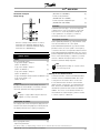
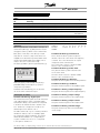
176FA145.16
VLT® 8000 AQUA
Operating Instructions
Software version: 1.7x
These Operating Instructions can be used for all VLT 8000 AQUA
frequency converters with software version 1.7x.
The software version number can be seen from parameter 624
Software version no.
4
MG.83.A2.02 - VLT is a registered Danfoss trademark
VLT® 8000 AQUA
AEO:
Automatic Energy Optimization - function that
dynamically adjusts the current supplied to a
variable torque load to optimize motor power
factor and motor efficiency.
analog inputs:
The analog inputs can be used for controlling various
functions of the frequency converter.
There are two types of analog inputs:
Current input, 0-20 mA
Voltage input, 0-10 V DC.
analog ref.
A signal transmitted to input 53, 54 or 60.
Can be voltage or current.
analog outputs:
There are two analog outputs, which are able to supply
a signal of 0-20 mA, 4-20 mA or a digital signal.
Automatic motor adjustment, AMA:
Automatic motor adjustment algorithm, which
determines the electrical parameters for the
connected motor, at standstill.
AWG:
AWG means American Wire Gauge, i.e. the American
measuring unit for cable cross-section.
Control command:
By means of the control unit and the digital inputs, it is
possible to start and stop the connected motor.
Functions are divided into two groups, with
the following priorities:
Group 1
Group 2
Reset, Coasting stop, Reset and
Coasting stop, DC braking, Stop and the
[OFF/ STOP] key.
Start, Pulse start, Reversing, Start
reversing, Jog and Freeze output
Group 1 functions are called Start-disable commands.
The difference between group 1 and group 2 is that
in group 1 all stop signals must be cancelled for the
motor to start. The motor can then be started by
means of a single start signal in group 2.
A stop command given as a group 1 command
results in the display indication STOP.
A missing stop command given as a group 2 command
results in the display indication STAND BY.
MG.83.A2.02 - VLT is a registered Danfoss trademark
CT:
Constant torque: used for e.g. heavy, solid
sludge pumps and centrifuges.
Digital inputs:
The digital inputs can be used for controlling various
functions of the frequency converter.
Introduction
■ Definitions
Definitions are given in alphabetical order.
Digital outputs:
There are four digital outputs, two of which activate
a relay switch. The outputs are able to supply
a 24 V DC (max. 40 mA) signal.
fJOG
The output frequency from the frequency converter
transmitted to the motor when the jog function is
activated (via digital terminals or serial communication).
fM
The output frequency from the frequency converter
transmitted to the motor.
fM,N
The rated motor frequency (nameplate data).
fMAX
Maximum output frequency transmitted to the motor.
fMIN
Minimum output frequency transmitted to the motor.
IM
The current transmitted to the motor.
IM,N
The rated motor current (nameplate data).
Initializing:
If initializing is carried out (see parameter 620
Operating mode), the frequency converter
returns to the factory setting.
IVLT,MAX
The maximum output current.
IVLT,N
The rated output current supplied by the
frequency converter.
LCP:
The control panel, which makes up a complete
interface for control and programming of VLT 8000
AQUA. The control panel is detachable and may,
as an alternative, be installed up to 3 metres away
5
VLT® 8000 AQUA
from the frequency converter, i.e. in a front panel,
by means of the installation kit option.
LSB:
Least significant bit.
Used in serial communication.
MCM:
Stands for Mille Circular Mil, an American measuring
unit for cable cross-section.
Setup:
There are four Setups, in which it is possible to
save parameter settings. It is possible to change
between the four parameter Setups and to edit one
Setup, while another Setup is active.
Start-disable command:
A stop command that belongs to group 1 of the
control commands - see this group.
MSB:
Most significant bit.
Used in serial communication.
Stop command:
See Control commands.
nM,N
The rated motor speed (nameplate data).
Thermistor:
A temperature-dependent resistor placed where the
temperature is to be monitored (VLT or motor).
ηVLT
The efficiency of the frequency converter is defined as
the ratio between the power output and the power input.
On-line/off-line parameters:
On-line parameters are activated immediately after the
data value is changed. Off-line parameters are not
activated until OK has been entered on the control unit.
PID:
The PID regulator maintains the desired speed
(pressure, temperature, etc.) by adjusting the output
frequency to match the varying load.
PM,N
The rated power delivered by the motor
(nameplate data).
Preset ref.
A permanently defined reference, which can be
set from -100% to +100% of the reference range.
There are four preset references, which can be
selected via the digital terminals.
RefMAX
The maximum value which the reference signal
may have. Set in parameter 205 Maximum
reference, RefMAX.
Trip:
A state which occurs in different situations, e.g.
if the frequency converter is subjected to an
over-temperature. A trip can be cancelled by pressing
reset or, in some cases, automatically.
Trip locked:
Trip locked is a state which occurs in different
situations, e.g. if the frequency converter is subject to
an over-temperature. A locked trip can be cancelled by
cutting off mains and restarting the frequency converter.
UM
The voltage transmitted to the motor.
UM,N
The rated motor voltage (nameplate data).
UVLT, MAX
The maximum output voltage.
VT characteristics:
Variable torque characteristics, used for
pumps and fans.
RefMIN
The smallest value which the reference signal may
have. Set in parameter 204 Minimum reference, RefMIN.
6
MG.83.A2.02 - VLT is a registered Danfoss trademark
The voltage of the frequency converter
is dangerous whenever the equipment
is connected to mains. Incorrect
installation of the motor or the frequency converter
may cause damage to the equipment, serious
personal injury or death.
Consequently, the instructions in this manual,
as well as national and local rules and safety
regulations, must be complied with.
117, Motor thermal protection). In UL/cUL
applications ETR provides Class 20, over-load
protection in accordance with the NEC ®.
6. Do not remove the plugs for the motor and
mains supply while the frequency converter is
connected to mains. Check that the mains supply
has been disconnected and that the necessary time
has passed before removing motor and mains plugs.
7. Please note that the frequency converter has more
voltage inputs than L1, L2, L3 when the DC-bus
terminals or AUX 24 V option are used.
Check that all voltage inputs have been
disconnected and that the necessary time has
passed before repair work is commenced.
Warning:
Touching the electrical parts may be fatal - even after the equipment has
been disconnected from line.
VLT 8006-8062, 200-240 V:
wait at least 15 minutes
VLT 8006-8072, 380-480 V:
wait at least 15 minutes
VLT 8102-8352, 380-480 V:
wait at least 20 minutes
VLT 8452-8652, 380-480 V:
wait at least 40 minutes
VLT 8002-8006, 525-600 V:
wait at least 4 minutes
VLT 8008-8027, 525-600 V:
wait at least 15 minutes
VLT 8032-8072, 525-600 V:
wait at least 30 minutes
VLT 8052-8402, 525-690 V:
wait at least 20 minutes
VLT 8502-8652, 525-690 V:
wait at least 30 minutes
MG.83.A2.02 - VLT is a registered Danfoss trademark
176FA159.15
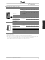
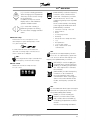
■ Safety regulations
1. The frequency converter must be disconnected
from the mains if repair work is to be carried out.
Check that the mains supply has been disconnected
and that the necessary time has passed before
removing motor and mains plugs.
2. The [OFF/STOP] key on the control panel of
■ Warning against unintended start
the frequency converter does not disconnect
1. The motor can be brought to a stop by means
the equipment from mains and is thus not to
of digital commands, bus commands, references
or a local stop, while the frequency converter
be used as a safety switch.
is connected to mains. If personal safety
3. Correct protective earthing/grounding of the
considerations make it necessary to ensure
equipment must be established, the user must be
that no unintended start occurs, these stop
protected against supply voltage, and the motor
must be protected against overload in accordance
functions are not sufficient.
with the National Electrical Code and local codes.
2. While parameters are being changed, the motor
4. The earth leakage currents are higher than 3.5mA.
may start. Consequently, the stop key [OFF/
5. Protection against motor overload is not included in
STOP] must always be activated, following
which data can be modified.
the factory setting. If this function is required, set
3. A stopped motor may start if a fault occurs in
parameter 117, Motor thermal protection, to data
the electronics of the frequency converter, or
value ETR trip or data value ETR warning.
if a temporary overload or a fault in the supply
Note: The function is initialised at 1.0 x rated motor
mains or the motor connection ceases.
current and rated motor frequency (see parameter
7
Introduction
VLT® 8000 AQUA
VLT® 8000 AQUA
■ Use on isolated mains
See section RFI Switch regarding use on isolated mains.
It is important to follow the recommendations regarding
installation on IT-mains, since sufficient protection
of the complete installation must be observed.
Not taking care using relevant monitoring devices
for IT-mains may result in damage.
It is the responsibility of the user or the
person installing the VLT to provide proper
earthing/grounding, as well as motor
overload and branch circuit protection according to
local codes such as the Nation Electrical Code (NEC).
NB!:
Electrostatic Precaution; Electrostatic discharge
(ESD). Many electronic components are
sensitive to static electricity. Voltages so low
that they cannot be felt, seen or heard, can reduce
the life, affect performance, or completely destroy
sensitive electronic components. When performing
service, proper ESD equipment should be used to
prevent possible damage from occurring.
The frequency converter contains dangerous
voltages when connected to mains voltage.
After disconnecting from mains wait at least
15 minutes for VLT 8006-8062, 200-240 V
15 minutes for VLT 8006-8072, 380-480 V
20 minutes for VLT 8102-8352, 380-480 V
40 minutes for VLT 8452-8652, 380-480 V
4 minutes for VLT 8002-8006, 525-600 V
15 minutes for VLT 8008-8027, 525-600 V
30 minutes for VLT 8032-8072, 525-600 V
20 minutes for VLT 8052-8402, 525-690 V
30 minutes for VLT 8502-8652, 525-690 V
before touching any electrical components. Also
make sure that other voltage inputs have been
disconnected, such as external 24 VDC and
load-sharing (linkage of DC intermediate circuit). Only
a competent electrician should carry out the electrical
installation. Improper installation of the motor or the
VLT may cause equipment failure, serious injury or
death. Follow this manual and National Electrical
Codes (NEC) and local safety codes.
8
MG.83.A2.02 - VLT is a registered Danfoss trademark
VLT® 8000 AQUA
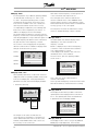
Introduction to AQUA:
This section tells you the advantages you can obtain by using a VLT
8000 AQUA - such as Automatic Energy Optimization, Constant Torque
or Variable Torque and other AQUA relevant functions.
This section also contains examples of applications as well as
information about Danfoss.
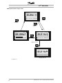
Installation:
This section tells you how to carry out a mechanically correct installation
of the VLT 8000 AQUA.
Furthermore, a list is given of mains and motor connections, together
with a description of the control card terminals.
Programming:
This section describes the control unit and the software parameters for
the VLT 8000 AQUA. Also included is a guide to the Quick Setup menu,
which allows you to get started on your application very quickly.
All about VLT 8000 AQUA:
This section gives information about status, warning and error messages
from the VLT 8000 AQUA. Additionally, information is given on technical
data, ser-vice, factory settings and special conditions.
Introduction
■ Introduction to Operating Instructions
These Operating Instructions are divided into four
sections with information about VLT 8000 AQUA.
NB!:
Indicates something to be noted by the reader.
Indicates a general warning
Indicates a high-voltage warning
MG.83.A2.02 - VLT is a registered Danfoss trademark
9
VLT® 8000 AQUA
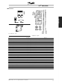
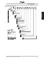
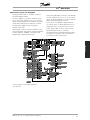
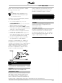
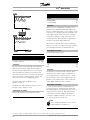
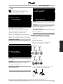
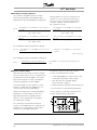
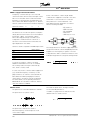
■ Control principle
A frequency converter rectifies AC voltage from
mains into DC voltage, after which this DC
voltage is converted into a AC current with a
variable amplitude and frequency.
1. Mains
3 x 200 3 x 380 3 x 525 3 x 525 -
voltage
240 V AC,
480 V AC,
600 V AC,
690 V AC,
50
50
50
50
/
/
/
/
60
60
60
60
Hz.
Hz.
Hz.
Hz.
2. Rectifier
A three-phase rectifier bridge that rectifies AC
current into DC current.
3. Intermediate circuit
DC voltage = 1.35 x mains voltage [V].
4. Intermediate circuit coils
Even out the intermediate circuit voltage and reduce
the harmonic current feedback to the mains supply.
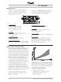
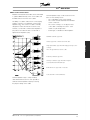
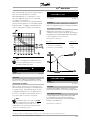
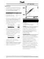
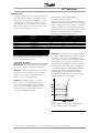
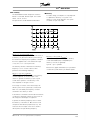
■ AEO - Automatic Energy Optimization
Normally, the U/f characteristics have to be set on the
basis of the expected load at different frequencies.
However, knowing the load at a given frequency in an
installation is often a problem. This problem can be
solved by using a VLT 8000 AQUA with its integral
Automatic Energy Optimization (AEO), which ensures
optimum energy utilization. All VLT 8000 AQUA units
feature this function as a factory setting, i.e. it is
not necessary to adjust the frequency converter U/f
ratio in order to obtain maximum energy savings.
In other frequency converters, the given load and
voltage/frequency ratio (U/f) must be assessed to carry
out correct setting of the frequency converter.
Using Automatic Energy Optimization (AEO), you
no longer need to calculate or assess the system
characteristics of the installation, since Danfoss VLT
8000 AQUA units guarantee optimum, load-dependent
energy consumption by the motor at all times.
The figure on the right illustrates the working
range of the AEO function, within which energy
optimization is enabled.
10
The motor is thus supplied with variable voltage and
frequency, which enables infinitely variable speed
control of three-phased, standard AC motors.
5. Intermediate circuit capacitors
Even out the intermediate circuit voltage.
6. Inverter
Converts DC voltage into variable AC voltage
with a variable frequency.
7. Motor voltage
Variable AC voltage, 0-100% of mains supply voltage.
8. Control card
This is where to find the computer that controls
the inverter which generates the pulse pattern by
which the DC voltage is converted into variable
AC voltage with a variable frequency.
If the AEO function has been selected in parameter 101,
Torque characteristics, this function will be constantly
active. If there is a major deviation from the optimum U/f
ratio, the frequency converter will quickly adjust itself.
Advantages of the AEO function
•
•
•
Automatic energy optimization
Compensation if an oversize motor is used
AEO matches operations to daily or
seasonal fluctuations
MG.83.A2.02 - VLT is a registered Danfoss trademark
VLT® 8000 AQUA
•
•
Introduction
•
Energy savings in a constant air volume system
Compensation in the oversynchronous
working range
Reduces acoustic motor noise
MG.83.A2.02 - VLT is a registered Danfoss trademark
11
VLT® 8000 AQUA
■ Example of application - Constant pressure
regulation in water supply system
The demand for water from waterworks varies considerably during the course of a day. In the night,
practically no water is used, while in the morning and in the evening the consumption is high. In order to
maintain a suitable pressure in the water supply lines in relation to the current demand, the water supply
pumps are equipped with speed control. The use of a frequency converter enables the energy consumed by
the pumps to be kept at a minimum, while optimizing the water supply to consumers.
A VLT 8000 AQUA with its integral PID controller ensures simple and quick installation. For example, an
IP54/NEMA 12 unit can be mounted close to the pump on the wall and the existing mains cables can be
used as mains supply to the frequency converter. A Pressure transmitter (e.g. Danfoss MBS 33 or MBS
3000) can be fitted a few meters (feet) from the joint outlet point from the waterworks to obtain closed loop
regulation. Danfoss MBS 33 and MBS 3000 is a two-wire transmitter (4-20 mA) that can be powered directly
from a VLT 8000 AQUA. The required setpoint (e.g. 5 bar) can be set locally in parameter 418 Setpoint 1.
Assume:
Transmitter is scaled 0-10 Bar, minimum flow
is achieved at 30 Hz. An increase in motor
speed increases the pressure.
Set the following parameters:
Par. 100
Configuration
Par. 201
Minimum Output Frequency
Par. 202
Maximum Output Frequency
Par. 204
Minimum Reference
Par. 205
Maximum Reference
Par. 302
Terminal 18 Digital inputs
Par. 314
Terminal 60, analog input current
Par. 315
Terminal 60, min. scaling
Par. 316
Terminal 60, max. scaling
Par. 403
Sleep mode timer
Par. 404
Sleep frequency
Par. 405
Wake-up frequency
Par. 406
Boost setpoint
Par. 413
Minimum Feedback
Par. 414
Maximum Feedback
Par. 415
Process units
Par. 418
Setpoint 1
Par. 420
PID control action
Par. 423
PID Proportional gain
Par. 424
PID Integral time
Closed loop [1]
30 Hz
50 Hz (or 60 Hz)
0 Bar
10 Bar
Start [1]
Feedback signal [2]
4 mA
20 mA
10 sec.
35 Hz
45 Hz
125%
0 Bar
10 Bar
Bar [16]
5 bar
Normal
0.3*
30 sec.*
* The PID tuning parameters depend on the actual system dynamics.
12
MG.83.A2.02 - VLT is a registered Danfoss trademark
■ PC software and serial communication
Danfoss offers various options for serial communication.
Using serial communication, it is possible to monitor,
program and control one or several frequency
converters from a centrally located computer.
All VLT 8000 AQUA units have an RS 485 port as
standard with a choice of two protocols. The protocols
selectable in parameter 500 protocols are:
• FC Protocol
• Modbus RTU
A bus option card allows higher transmission speed
than RS 485. In addition, a higher number of units
can be linked to the bus and alternative transmission
media can be used. Danfoss offers the following
option cards for communication:
• Profibus
• LonWorks
• DeviceNet
Information on the installation of various options is
not included in these operating instructions.
MCT 10 Set-up Software
MCT 10 has been designed as an easy to use interactive
tool for setting parameters in our frequency converters.
The MCT 10 Set-up Software will be useful for:
• Planning a communication network off-line. MCT 10
contains a complete frequency converter database
• Commissioning frequency converters on line
• Saving settings for all frequency converters
• Replacing a drive in a network
• Expanding an existing network
• Future developed drives will be supported
MCT 10 Set-up Software support Profibus DP-V1 via
a Master class 2 connection. It makes it possible to
on line read/write parameters in a frequency converter
via the Profibus network. This will eliminate the need
for an extra communication network.
The MCT 10 Set-up Software Modules
The following modules are included in the
software package:
MCT 10 Set-up Software
Using the RS 485 port enables communication,
e.g. with a PC. A Windows TM program, called
MCT 10, is available for this purpose. It can be
used to monitor, program and control one or
several VLT 8000 AQUA units.
Setting parameters
Copy to and from frequency converters
Documentation and print out of parameter
settings incl. diagrams
SyncPos
Creating SyncPos programme
■ PC Software tools
PC Software - MCT 10
All drives are equipped with a serial communication
port. We provide a PC tool for communication
between PC and frequency converter, VLT Motion
Control Tool MCT 10 Set-up Software.
Ordering number:
Please order your CD containing MCT 10 Set-up
Software using code number 130B1000.
■ Fieldbus options
The increasing need for information in building
■ Profibus
management systems makes it necessary to collect
Profibus is a fieldbus system with FMS and DP,
or visualise many different types of process data.
which can be used for linking automation units,
Important process data can help the system technician
such as sensors and actuators, to the controls
in the day to day monitoring of the system, which
by means of a two-conductor cable.
means that a negative development, e. g. an increase
in energy consumption, can be rectified in time.
Profibus FMS is used if major communication
tasks are to be solved at cell and system level by
The substantial amount of data in large buildings
means of large volumes of data.
may generate a need for a higher transmission
speed than 9600 baud.
Profibus DP is an extremely fast communication
protocol, made specially for communication between
the automation system and various units.
VLT 8000 AQUA only supports DP.
MG.83.A2.02 - VLT is a registered Danfoss trademark
13
Introduction
VLT® 8000 AQUA
VLT® 8000 AQUA
■ LON - Local Operating Network
LonWorks is an intelligent fieldbus system which
improves the possibility of decentralising control,
as communication is enabled between individual
units in the same system (Peer-to-Peer).
This means that there is no need for a big main station
for handling all the signals of the system (Master-Slave).
Signals are sent direct to the unit that needs them
via a common network medium. This makes
communication much more flexible and the central
building state control and monitoring system can be
changed into a dedicated building state monitoring
system whose task is to ensure that everything is
running as planned. If the potential of LonWorks is
fully utilised, sensors will also be connected to the
bus, which means that a sensor signal can quickly
be moved to another controller. If room dividers are
mobile, this is a particularly useful feature.
■ DeviceNet
DeviceNet is a digital, multi-drop network, based
on the CAN protocol, that connects and serves
as a communication network between industrial
controllers and I/O devices.
Each device and/or controller is a node on the
network. DeviceNet is a producer-consumer
network that supports multiple communication
hierarchies and message prioritization.
DeviceNet systems can be configured to operate in a
master-slave or a distributed control architecture using
peer-to-peer communication. This system offers a
single point of connection for configuration and control
by supporting both I/O and explicit messaging.
DeviceNet also has the feature of having power
on the network. This allows devices with limited
power requirements to be powered directly from
the network via the 5-conductor cable.
■ Modbus RTU
MODBUS RTU (Remote Terminal Unit) Protocol is
a messaging structure developed by Modicon in
1979, used to establish master-slave/client-server
communication between intelligent devices.
MODBUS is used to monitor and program
devices; to communicate intelligent devices
with sensors and instruments; to monitor field
devices using PCs and HMIs.
MODBUS is often applied in Gas and Oil applications,
but also in building, infrastructure, transportation and
energy, applications are making use of its benefits.
14
MG.83.A2.02 - VLT is a registered Danfoss trademark
VLT® 8000 AQUA
Introduction
■ Accessories
IP 20 bottom cover
Application option
Type
IP 4x top cover IP
IP 4 x top cover
1)
1)
Description
Order no.
Option, VLT type 8006-8011 380-480 V compact
175Z0928
Option, VLT type 8002-8011 525-600 V compact
175Z0928
Option, VLT type 8006-8011 380-480 V
175H4195
IP 20 terminal cover
Option, VLT type 8006-8022 200-240 V
175Z4622
IP 20 terminal cover
Option, VLT type 8027-8032 200-240 V
175Z4623
IP 20 terminal cover
Option, VLT type 8016-8042 380-480 V
175Z4622
IP 20 terminal cover
Option, VLT type 8016-8042 525-600 V
175Z4622
IP 20 terminal cover
Option, VLT type 8052-8072 380-480 V
175Z4623
IP 20 terminal cover
Option, VLT type 8102-8122 380-480 V
175Z4280
IP 20 terminal cover
Option, VLT type 8052-8072 525-600 V
175Z4623
IP 20 bottom cover
Option, VLT type 8042-8062 200-240 V
176F1800
Terminal adaptor kit
VLT type 8042-8062 200-240 V, IP 54
176F1808
Terminal adaptor kit
VLT type 8042-8062 200-240 V, IP 00/NEMA 1
176F1805
Control panel LCP
Separate LCP
175Z7804
LCP remote-mounting kit IP 00 & 203)
Remote-mounting kit, incl. 3 m cable
175Z0850
NEMA 12 bonding plate
2)
LCP remote-mounting kit IP 54
4)
LCP blind cover
Remote-mounting kit, incl. 3 m cable
175Z7802
for all IP00/IP20 drives
175Z7806
Cable for LCP
Separate cable (3 m)
175Z0929
Relay card
Application card with four relay outputs
175Z3691
Cascade controller card
With conformal coating
175Z3692
Profibus option
Without/with conformal coating
175Z3685/175Z3686
LonWorks option, Free topology
Without conformal coating
176F0225
Modbus RTU option
Without conformal coating
175Z3362
DeviceNet option
Without conformal coating
176F0224
MCT 10 Set-up software
CD-Rom
130B1000
MCT 31 Harmonic calculation
CD-Rom
130B1031
MG.83.A2.02 - VLT is a registered Danfoss trademark
15
VLT® 8000 AQUA
Rittal Installation Kit
Type
Description
Order No.
Rittal TS8 enclosure for IP005)
Installation kit for 1800mm high enclosure, VLT8152-8202, 380-480V; VLT8052-8202, 525-690V
176F1824
Rittal TS8 enclosure for IP005)
Installation kit for 2000mm high enclosure, VLT8152-8202, 380-480V; VLT8052-8202, 525-690V
176F1826
Rittal TS8 enclosure for IP005)
Installation kit for 1800mm high enclosure, VLT8252-8352, 380-480V; VLT8252-8402, 525-690V
176F1823
Rittal TS8 enclosure for IP005)
Installation kit for 2000mm high enclosure, VLT8252-8352, 380-480V; VLT8252-8402, 525-690V
176F1825
Rittal TS8 enclosure for IP005)
Installation kit for 2000mm high enclosure, VLT8452-8652, 380-480V/VLT 8502-8652, 525-690V
176F1850
Floor stand for IP21 and IP54
Option, VLT8152-8352, 380-480V; VLT 8052-8402, 525-690V
176F1827
Mains shield kit
Protection kit, VLT 8152-8352, 380-480 V; VLT 8052-8402, 525-690 V
176F0799
Mains shield kit
Protection kit, VLT 8452-8652, 380-480 V; VLT 8502-8652, 525-690V
176F1851
enclosure5)
1) IP 4x/NEMA 1 top cover is for IP 20 units only and only horizontal surfaces comply with IP 4x. The kit also
contains a bonding plate (UL).
2) NEMA 12 bonding plate (UL) is only for IP 54 units.
3) The remote-mounting kit is only for IP 00 and IP 20 units. Enclosure of the remote-mounting kit is IP 65.
4) The remote-mounting kit is only for IP 54 units. Enclosure of the remote-mounting kit is IP 65.
5) For details: See High Power Installation Guide, MI.90.JX.YY.
VLT 8000 AQUA is available with an integral fieldbus option or application option. Ordering numbers for the
individual VLT types with integrated options can be seen from the relevant manuals or instructions. In addition,
the ordering number system can be used for ordering a frequency converter with an option.
16
MG.83.A2.02 - VLT is a registered Danfoss trademark
VLT® 8000 AQUA
In "Master/Slave Mode", the drive that has the
Cascade Controller option card installed in it, along
with its associated motor, is designated as the
master. Up to four additional motors, each with
its own drive, can be operated in slave mode. The
Cascade Controller functions to stage the slave
drives/motors - on & off (as required), as a function
of "best system operating efficiency".
This filter reduces the voltage rise time, the peak voltage
UPEAK and the ripple current I to the motor, thereby
making current and voltage almost sinusoidal. The
acoustic motor noise is therefore reduced to a minimum.
Because of the ripple current in the coils, there will be
some noise from the coils. This problem can be solved
entirely by integrating the filter in a cabinet or similar.
In "Lead Pump Alternation Mode", it is possible to
average out the usage of the pumps. This is done by
making the frequency converter switch between the
pumps (max. 4) by means of a timer. Please note
that this mode requires an external relay setup.
Consult your Danfoss Sales Office for
additional information.
■ LC filters for VLT 8000 AQUA
When a motor is controlled by a frequency converter,
resonance noise will be heard from the motor. This
noise, which is caused by the design of the motor,
occurs each time one of the inverter switches in
the frequency converter is activated. Consequently,
the resonance noise frequency corresponds to the
switching frequency of the frequency converter.
For the VLT 8000 AQUA, Danfoss offers a LC filter
to dampen the acoustic motor noise.
■ Examples of the use of LC filters
Submersible pumps
For small motors with up to and including 5.5 kW
rated motor power, use an LC filter, unless the motor
is equipped with phase separation paper. This applies
e.g. to all wet running motors. If these motors are
used without LC filter in connection with a frequency
converter, the motor windings will short-circuit. If in
doubt, ask the motor manufacturer whether the motor
in question is equipped with phase separation paper.
Well pumps
If immersion pumps are used, e.g. submerged
pumps or well pumps, the supplier should be
contacted for clarification of requirements. It is
recommended to use a LC filter if a frequency converter
is used for well pump applications.
MG.83.A2.02 - VLT is a registered Danfoss trademark
17
Introduction
■ Cascade Controller Option
In "Standard Mode", one motor is controlled by
the drive that has the Cascade Controller Option
card installed in it. Up to four additional fixed speed
motors can be sequenced on & off, as required
by the process, in lead-lag mode.
VLT® 8000 AQUA
■ Ordering numbers, LC filter modules
Mains supply 3 x 200 - 240 V
LC filter
LC filter
for VLT type
enclosure
8006-8008
IP 00
8011
IP 00
8016
IP 00
8022
IP 00
8027
IP 00
8032
IP 00
8042
IP 00
8052
IP 00
8062
IP 00
Rated current
at 200 V
25.0 A
32 A
46 A
61 A
73 A
88 A
115 A
143 A
170 A
Max. output
frequency
60 Hz
60 Hz
60 Hz
60 Hz
60 Hz
60 Hz
60 Hz
60 Hz
60 Hz
Power
loss
110 W
120 W
150 W
210 W
290 W
320 W
600 W
600 W
700 W
Mains supply 3 x 380 - 480
LC filter
LC filter
for VLT type
enclosure
8006-8011
IP 20
8016
IP 00
8022
IP 00
8027
IP 00
8032
IP 00
8042
IP 00
8052
IP 00
8062
IP 00
8072
IP 20
8102
IP 20
8122
IP 20
8152
IP 20
8202
IP 20
8252
IP 20
8302
IP 20
8352
IP 20
8452
IP 20
8502
IP 20
8602
IP 20
Rated current
at 400/480 V
16 A / 16 A
24 A/ 21.7 A
32 A / 27.9 A
37.5 A / 32 A
44 A / 41.4 A
61 A / 54 A
73 A / 65 A
90 A / 78 A
106 A / 106 A
147 A / 130 A
177 A / 160 A
212 A / 190 A
260 A / 240 A
315 A / 302 A
395 A / 361 A
480 A / 443 A
600 A / 540 A
658 A / 590 A
745 A / 678 A
Max. output
frequency
120 Hz
60 Hz
60 Hz
60 Hz
60 Hz
60 Hz
60 Hz
60 Hz
60 Hz
60 Hz
60 Hz
60 Hz
60 Hz
60 Hz
60 Hz
60 Hz
60 Hz
60 Hz
60 Hz
Power
loss
170 W
180 W
190 W
210 W
290 W
410 W
480 W
500 W
600 W
750 W
750 W
900 W
1000 W
1100 W
1700 W
2100 W
2100 W
2500 W
Order no.
175Z4600
175Z4601
175Z4602
175Z4603
175Z4604
175Z4605
175Z4702
175Z4702
175Z4703
Order no.
175Z0832
175Z4606
175Z4607
175Z4608
175Z4609
175Z4610
175Z4611
175Z4612
175Z4701
175Z4702
175Z4703
175Z4704
175Z4705
175Z4706
175Z4707
175Z3139
175Z3140
175Z3141
175Z3142
Regarding LC filters for 525 - 600 V and VLT 8652,
380-480 V, please contact Danfoss.
NB!:
When using LC filters, the switching frequency
must be 4.5 kHz (see parameter 407).
For VLT 8452-8602 parameter 408 must be set to
LC filter fitted to obtain proper operation.
18
MG.83.A2.02 - VLT is a registered Danfoss trademark
VLT® 8000 AQUA
Mains supply 3 x 690 V
8052
8062
8072
8102
8122
8152
8202
8252
8302
8352
8402
8502
8602
8652
Rated Current at 690
V
54
73
86
108
131
155
192
242
290
344
400
530
600
630
Max. output
frequency (Hz)
60
60
60
60
60
60
60
60
60
60
60
60
60
60
Power
dissipation (W)
290
390
480
600
550
680
920
750
1000
1050
1150
500
570
600
Ordering no. IP00
130B2223
130B2225
130B2225
130B2226
130B2228
130B2228
130B2229
130B2231
130B2231
130B2232
130B2234
130B2241
130B2242
-
Ordering no.
IP20
130B2258
130B2260
130B2260
130B2261
130B2263
130B2263
130B2264
130B2266
130B2266
130B2267
130B2269
130B2270
130B2271
-
Introduction
VLT
dU/dt filters
The dU/dt filters reduce dU/dt to approx. 500 V / µsec. These filters do not reduce noise or Upeak.
NB!:
When using dU/dt filters, the switching
frequency must be 1.5 kHz (see parameter 411)
Mains supply 3 x 690 V
VLT
8052
8062
8072
8102
8122
8152
8202
8252
8302
8352
8402
8502
8602
8652
Rated Current at 690
V
54
73
86
108
131
155
192
242
290
344
400
530
600
630
Max. output
frequency (Hz)
60
60
60
60
60
60
60
60
60
60
60
60
60
60
MG.83.A2.02 - VLT is a registered Danfoss trademark
Power
dissipation (W)
90
100
110
120
150
180
190
210
350
480
540
500
570
600
Ordering no. IP 00
130B2154
130B2155
130B2156
130B2157
130B2158
130B2159
130B2160
130B2161
130B2162
130B2163
130B2165
130B2236
130B2237
-
Ordering no.
IP20
130B2188
130B2189
130B2190
130B2191
130B2192
130B2193
130B2194
130B2195
130B2196
130B2197
130B2199
130B2239
130B2240
-
19
VLT® 8000 AQUA
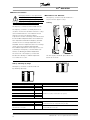
■ LC filters VLT 8006-8011 380 - 480 V
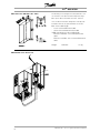
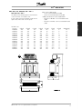
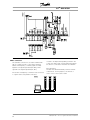
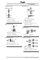
The drawing on the left gives the measurements of IP
20 LC filters for the above-mentioned power range.
Min. space above and under enclosure: 100 mm.
IP 20 LC filters have been designed for side-by-side
installation without any space between enclosures.
Max. motor cable length:
- 150 m screened/armoured cable
- 300 m unscreened/unarmoured cable
If EMC standards are to be complied with:
EN 55011-1B: Max. 50 screened/armoured
cable
EN 55011-1A: Max. 150 m screened/armoured
cable
Weight:
175Z0832
9.5 kg
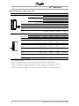
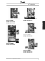
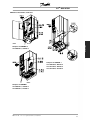
■ Installation of LC filter IP 20
20
MG.83.A2.02 - VLT is a registered Danfoss trademark
VLT® 8000 AQUA
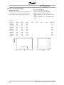
LC filter IP 00
LC type
A [mm]
175Z4600
220
175Z4601
220
175Z4602
250
175Z4603
295
175Z4604
355
175Z4605
360
175Z4606
280
175Z4607
280
175Z4608
280
175Z4609
295
175Z4610
355
175Z4611
355
175Z4612
405
B [mm]
135
145
165
200
205
215
170
175
180
200
205
235
230
C [mm]
92
102
117
151
152
165
121
125
131
151
152
177
163
MG.83.A2.02 - VLT is a registered Danfoss trademark
Max. motor cable length:
- 150 m screened/armoured cable
- 300 m unscreened/unarmoured cable
If EMC standards are to be complied with:
- EN 55011-1B: Max. 50 screened/armoured
cable
- EN 55011-1A: Max. 150 m screened/armoured
cable
D [mm]
190
190
210
240
300
300
240
240
240
240
300
300
360
E [mm]
68
78
92
126
121
134
96
100
106
126
121
146
126
F [mm]
170
170
180
190
240
240
190
190
190
190
240
240
310
G [mm]
8
8
8
11
11
11
11
11
11
11
11
11
11
Weight [kg]
10
13
17
29
38
49
18
20
23
29
38
50
65
21
Introduction
■ LC filters VLT 8006-8032, 200 - 240 V /
8016-8062 380 - 480 V
The table and the drawing give the measurements
of IP 00 LC filters for Compact units.
IP 00 LC filters must be integrated and protected
against dust, water and corrosive gases.
VLT® 8000 AQUA
■ LC filter VLT 8042-8062 200-240 V /
8072-8602 380 - 480 V
The table and the drawing give the measurements of IP
20 LC filters. IP 20 LC filters must be integrated and
protected against dust, water and aggressive gases.
LC-filter IP 20
LC type
A [mm]
175Z4701
740
175Z4702
740
175Z4703
740
175Z4704
740
175Z4705
830
175Z4706
830
175Z4707
830
175Z3139
1350
175Z3140
1350
175Z3141
1350
175Z3142
1350
22
B [mm]
550
550
550
550
630
630
630
800
800
800
800
C [mm]
600
600
600
600
650
650
650
1000
1000
1000
1000
Max. motor cable length:
- 150 m screened/armoured cable
- 300 m unscreened/unarmoured cable
If EMC standards are to be complied with:
- EN 55011-1B: Max. 50 m screened/armoured
cable
- EN 55011-1A: Max. 150 m screened/armoured
cable
D [mm]
E [mm]
F [mm]
G [mm]
Weight [kg]
70
70
110
120
220
250
250
350
400
400
470
MG.83.A2.02 - VLT is a registered Danfoss trademark
VLT® 8000 AQUA
Higher total current to be handled by the installations
- Increases load on transformer (sometimes it will
require a larger transformer, particular at retrofit)
- Increases heat losses in transformer and installation
- In some cases demands larger cables,
switches and fuses
Higher voltage distortion due to higher current
- Increase risk for disturbing electronic equipment
connected to same grid
A high percentage of rectifier load from eg frequency
converters, will increase the harmonic current, which
must be reduced to avoid the above consequences.
Therefore the frequency converter has as standard,
built in DC coils reducing the total current with about
40% (compared to devices without any arrangement
for harmonic suppression), down to 40-45% ThiD.
In some cases there is a need for further suppression
(eg retrofit with frequency converters). For this purpose
Danfoss can offer two advanced harmonic filters
AHF05 and AHF10, bringing the harmonic current
down to around 5% and 10% respectively. For further
details see instruction MG.80.BX.YY.
MCT 31
The MCT 31 harmonic calculation PC tool enables
easy estimation of the harmonic distortion in a given
application. Both the harmonic distortion of Danfoss
frequency converters as well as non-Danfoss frequency
converters with different additional harmonic reduction
measurements, such as Danfoss AHF filters and
12-18-pulse rectifiers, can be calculated.
Ordering number:
Please order your CD containing the MCT 31 PC
tool using code number 130B1031.
■ Ordering numbers, Harmonic filters
Harmonic filters are used to reduce mains harmonics
• AHF 010: 10% current distortion
• AHF 005: 5% current distortion
380-415 V, 50 Hz
IAHF,N
Typical Motor Used
[kW]
10 A
19 A
26 A
35 A
43 A
72 A
101 A
144 A
180 A
217 A
289 A
324 A
370 A
Higher ratings can be achieved by
434 A
578 A
613 A
648 A
740 A
Danfoss ordering number
AHF 005
AHF 010
4, 5.5
7.5
11
15, 18.5
22
30, 37
45. 55
75
90
110
132, 160
200
paralleling the filter units
250
315
355
400
450
MG.83.A2.02 - VLT is a registered Danfoss trademark
175G6600
175G6601
175G6602
175G6603
175G6604
175G6605
175G6606
175G6607
175G6608
175G6609
175G6610
175G6611
175G6688
175G6622
175G6623
175G6624
175G6625
175G6626
175G6627
175G6628
175G6629
175G6630
175G6631
175G6632
175G6633
175G6691
Two 217 A units
Two 289 A units
289 A and 324 A units
Two 324 A units
Two 370 A units
VLT 8000
8006, 8008
8011, 8016
8022
8027
8032
8042, 8052
8062, 8072
8102
8122
8152
8202, 8252
8302
8352
8452
8502
8602
8652
23
Introduction
■ Harmonic filter
Harmonic currents do not directly affect the electricity
consumption but has an impact on following conditions:
VLT® 8000 AQUA
Please note that the matching of the typical Danfoss frequency converter and filter is pre-calculated based on
400 V and assuming typical motor load (4 or 2 pole motor). VLT 8000 is based on a max. 110% torque
application.
The pre-calculated filter current may be different than the input current ratings of VLT 8000 as stated in the
respective operating instructions, as these numbers are based on different operating conditions.
440-480 V, 60 Hz
IAHF,N
Typical Motor Used
[HP]
19 A
26 A
35 A
43 A
72 A
101 A
144 A
180 A
217 A
289 A
324 A
370 A
Higher ratings can be achieved by
506 A
578 A
578 A
648 A
Danfoss ordering number
AHF 005
AHF 010
10, 15
20
25, 30
40
50, 60
75
100, 125
150
200
250
300
350
paralleling the filter units
450
500
550
600
175G6612
175G6613
175G6614
175G6615
175G6616
175G6617
175G6618
175G6619
175G6620
175G6621
175G6689
175G6690
175G6634
175G6635
175G6636
175G6637
175G6638
175G6639
175G6640
175G6641
175G6642
175G6643
175G6692
175G6693
VLT 8000
8011, 8016
8022
8027, 8032
8042
8052, 8062
8072
8102, 8122
8152
8202
8252
8302
8352
217 A and 289 A units
Two 289 A units
Two 289 A units
Two 324 A units
8452
8502
8602
8652
Please note that the matching of the Danfoss frequency converter and filter is pre-calculated based on 480 V
and assuming typical motor load. VLT 8000 is based on 110 % torque application.
The pre-calculated filter current may be varying from the input current ratings of VLT 8000 as stated in the
respective operating instructions, as these numbers are based on different operating conditions.
690 V, 50 Hz
24
I AHF,N
43
72
101
144
180
217
289
324
370
469
Typical motor used
37, 45
55, 75
90
110, 132
160
200
250
315
400
500
Ordering no. AHF 005
130B2328
130B2330
130B2331
130B2333
130B2334
130B2335
130B2331 & 130B2333
130B2333 & 130B2334
130B2334 & 130B2335
130B2333 & 2 x
Ordering no. AHF 010
130B2293
130B2295
130B2296
130B2298
130B2299
130B2300
130B2301
130B2302
130B2304
130B2299 & 130B2301
VLT 8000 110%
8052
8062, 8072
8102
8122, 8152
8202
8252
8302
8352
8402
8502
578
613
560
630
130B2334
3 x 130B2334
3 x 130B2335
2 x 130B2301
130B2301 & 130B2302
8602
8652
MG.83.A2.02 - VLT is a registered Danfoss trademark
■ Unpacking and ordering a VLT frequency converter
If you are in doubt as to which frequency converter
you have received and which options it contains,
use the following to find out.
■ Type code ordering number string
On the basis of your order, the frequency converter is
given an ordering number that can be seen from the
nameplate on the unit. The number may look as follows:
VLT-8008-A-T4-C20-R3-DL-F10-A00-C0
This means that the frequency converter ordered is a
VLT 8008 for three-phase mains voltage of 380-480 V
(T4) in Compact enclosure IP 20 (C20). The hardware
variant is with integral RFI filter, classes A & B (R3). The
frequency converter features a control unit (DL) with a
PROFIBUS option card (F10). No option card (A00)
and no conformal coating (C0) Character no. 8 (A)
indicates the application range of the unit: A = AQUA.
IP 00: This enclosure is only available for the larger
power sizes of the VLT 8000 AQUA series. It is
recommended for installation in standard cabinets.
IP 20/NEMA 1: This enclosure is used as standard
enclosure for VLT 8000 AQUA. It is ideal for
cabinet installation in areas where a high degree
of protection is required. This enclose also
permits side-by-side installation.
IP 54: This enclosure can be fitted direct to the
wall. Cabinets are not required. IP 54 units can
also be installed side-by-side.
Hardware variant
The units in the programme are available in the
following hardware variants:
ST:
Standard unit with or without control
unit. Without DC terminals, except for
VLT 8042-8062, 200-240 V
VLT 8016-8300, 525-600 V
SL:
Standard unit with DC terminals.
EX:
Extended unit with control unit, DC
terminals, connection of external 24 V
DC supply for back-up of control PCB.
DX:
Extended unit with control unit, DC
terminals, built-in mains fuses and
disconnector, connection of external 24
V DC supply for back-up of control PCB.
PF:
Standard unit with 24 V DC supply for
back-up of control PCB and built-in
main fuses. No DC terminals.
PS:
Standard unit with 24 V DC supply
for back-up of control PCB. No DC
terminals.
PD:
Standard unit with 24 V DC supply for
back-up of control PCB, built-in main
fuses and disconnect. No DC terminals.
RFI filter
Units for a mains voltage of 380-480 V and a motor
power of up to 7.5 kW (VLT 8011) are always
supplied with an integral class A1 & B filter. Units
for higher motor power than these can be ordered
either with or without an RFI filter. RFI filters are not
available for 525-600 V units.
A1 RFI is not offered on the VLT 8502 -8652 525-690V
Control unit (keypad and display)
All types of units in the programme, except for IP
54 units (and IP 21 VLT 8452-8652, 380-480 V and
VLT 8502-8652, 525-690 V), can be ordered either
with or without the control unit. IP 54 units always
come with a control unit.
All types of units in the programme are available
with built-in application options including a relay
card with four relays or a cascade controller card.
Conformal Coating
All types of units in the programme are available
with or without conformal coating of the PCB.
Please note VLT 8452-8652, 380-480 V and
VLT 8052-8652, 525-690 V are only available as
conformal coated.
MG.83.A2.02 - VLT is a registered Danfoss trademark
25
Introduction
VLT® 8000 AQUA
VLT® 8000 AQUA
200-240 V
Typecode
Position in string
4.0 kW/5.0 HP
5.5 kW/7.5 HP
7.5 kW/10 HP
11 kW/15 HP
15 kW/20 HP
18.5 kW/25 HP
22 kW/30 HP
30 kW/40 HP
37 kW/50 HP
45 kW/60 HP
T2
C00
C20
CN1
C54
ST
SL
R0
R1
R3
9-10
8006
8008
8011
8016
8022
8027
8032
8042
8052
8062
11-13
11-13
X
X
X
X
X
X
X
11-13
11-13
X
X
X
X
X
X
X
X
X
X
14-15
X
X
X
X
X
X
X
X
X
X
14-15
X
X
X
X
X
X
X
16-17
X
X
X
X
X
X
X
X
X
X
16-17
16-17
X
X
X
X
X
X
X
X
X
X
X
X
X
X
X
X
380-480 V
Typecode
T4
Position in string
4.0 kW/5.0 HP
5.5 kW/7.5 HP
7.5 kW/10 HP
11 kW/15 HP
15 kW/20 HP
18.5 kW/25 HP
22 kW/30 HP
30 kW/40 HP
37 kW/50 HP
45 kW/60 HP
55 kW/75 HP
75 kW/100 HP
90 kW/125 HP
110 kW/150 HP
132 kW/200 HP
160 kW/250 HP
200 kW/300 HP
250 kW/350 HP
315 kW/450 HP
355 kW/500 HP
400 kW/550 HP
450 kW/600 HP
9-10
8006
8008
8011
8016
8022
8027
8032
8042
8052
8062
8072
8102
8122
8152
8202
8252
8302
8352
8452
8502
8602
8652
C00
C20
CN1
C54
ST
SL
EX
DX
PS
PD
PF
R0
R1
R3
11-13 11-13 11-13 11-13 14-15 14-15 14-15 14-15 14-15 14-15 14-15 16-17 16-17 16-17
X
X
X
X
X
X
X
X
X
X
X
X
X
X
X
X
X
X
X
X
X
X
X
X
X
X
X
X
X
X
X
X
X
X
X
X
X
X
X
X
X
X
X
X
X
X
X
X
X
X
X
X
X
X
X
X
X
X
X
X
X
X
X
X
X
X
X
X
X
X
X
X
X
X
X
X
X
X
X
X
X
X
X
X
X
X
X
X
X
X
X
X
X
X
X
X
X
X
X
X
X
X
X
X
X
X
X
X
X
X
X
X
X
X
X
X
X
X
X
X
X
X
X
X
X
X
X
X
X
X
X
X
X
X
X
X
X
X
X
X
X
X
X
X
X
X
X
X
X
X
X
X
X
X
X
X
X
X
X
X
X
X
X
X
X
X
X
X
X
X
X
X
X
X
X
X
X
X
X
X
X
X
X
X
Voltage
Hardware variant
T2: 200-240 VAC
ST: Standard
T4: 380-480 VAC
SL: Standard with DC terminals
Enclosure
EX: Extended with 24 V supply and DC terminals
C00: Compact IP 00
DX: Extended with 24 V supply, DC terminals, disconnect and fuse
C20: Compact IP 20
PS: Standard with 24 V supply
CN1: Compact NEMA 1
PD: Standard with 24 V supply, fuse and disconnect
C54: Compact IP 54
PF: Standard with 24 V supply and fuse
RFI filter
R0: Without filter
R1: Class A1 filter
R3: Class A1 and B filter
NB!:
NEMA 1 exceeds IP 20
26
MG.83.A2.02 - VLT is a registered Danfoss trademark
VLT® 8000 AQUA
Typecode
Position in string
1.1 kW/1.5 HP
1.5 kW/2.0 HP
2.2 kW/3.0 HP
3.0 kW/4.0 HP
4.0 kW/5.0 HP
5.5 kW/7.5 HP
7.5 kW/10 HP
11 kW/15 HP
15 kW/20 HP
18.5 kW/25 HP
22 kW/30 HP
30 kW/40 HP
37 kW/50 HP
45 kW/60 HP
55 kW/75 HP
T6
C00
C20
CN1
ST
R0
9-10
8002
8003
8004
8005
8006
8008
8011
8016
8022
8027
8032
8042
8052
8062
8072
11-13
11-13
X
X
X
X
X
X
X
11-13
X
X
X
X
X
X
X
X
X
X
X
X
X
X
X
14-15
X
X
X
X
X
X
X
X
X
X
X
X
X
X
X
16-17
X
X
X
X
X
X
X
X
X
X
X
X
X
X
X
Introduction
525-600 V
525-690 V
T7
C00
Position in string
45 kW/50 HP
55 kW/60 HP
75 kW/75 HP
Typecode
9-10
8052
8062
8072
11-13
X
X
X
90 kW/100 HP
110 kW/125 HP
132 kW/150 HP
160 kW/200 HP
200 kW/250 HP
250 kW/300 HP
315 kW/350 HP
400 kW/400 HP
500 kW/400 HP
560 kW/500 HP
630 kW/600 HP
8102
8122
8152
8202
8252
8302
8352
8402
8502
8602
8652
X
X
X
X
X
X
X
X
X
X
X
CN1
C54
11-13 11-13
X
X
X
X
X
X
X
X
X
X
X
X
X
X
X
X
X
X
X
X
X
X
X
X
X
X
X
X
ST
EX
DX
PS
PD
PF
11-13 11-13 14-15 14-15 14-15 14-15
X
X
X
X
X
X
X
X
X
X
X
X
X
X
X
X
X
X
X
X
X
X
X
X
X
X
X
X
X
X
X
X
X
X
X
X
X
X
X
X
X
X
X
X
X
X
X
X
X
X
X
X
X
X
X
X
X
X
X
X
X
X
X
X
X
X
X
X
X
X
X
X
X
X
X
X
X
X
X
X
X
X
X
X
R0
R1
16-17 16-171)
X
X
X
X
X
X
X
X
X
X
X
X
X
X
X
X
X
X
X
X
X
X
X
X
X
1) R1 is not available with DX, PF and PD variants.
T7: 525-690 VAC
CN1: Compact NEMA 1
C00: Compact IP 00
ST: Standard
C20: Compact IP 20
R0: Without filter
R1: Class A1 filter
NB!:
NEMA 1 exceeds IP 20
MG.83.A2.02 - VLT is a registered Danfoss trademark
27
VLT® 8000 AQUA
Optional selections, 200-600 V
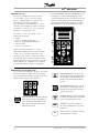
Display
D01)
Without LCP
DL
With LCP
Position: 18-19
Fieldbus option
F00
No options
F10
Profibus DP V1
F30
DeviceNet
F40
LonWorks free topology
Position: 20-22
Application option
A00
No options
A312) Relay card 4 relays
A32
Cascade Controller
Position: 23-25
Coating
C03)
No coating
C1
With coating
Position: 26-27
1) Not available with enclosure compact IP 54
2) Not available with fieldbus options (Fxx)
3) Not available for power sizes from 8452 to 8652, 380-480 V and VLT
8052-8652, 525-690 V
28
MG.83.A2.02 - VLT is a registered Danfoss trademark
VLT® 8000 AQUA
Introduction
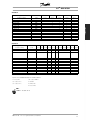
■ TYPE CODE Table/Ordering form
MG.83.A2.02 - VLT is a registered Danfoss trademark
29
VLT® 8000 AQUA
■ General technical data
Mains supply (L1, L2, L3):
Supply voltage 200-240 V units ........................................................................ 3 x 200/208/220/230/240 V ±10%
Supply voltage 380-480 V units ................................................................ 3 x 380/400/415/440/460/480 V ±10%
Supply voltage 525-600 V units ............................................................................... 3 x 525/550/575/600 V ±10%
Supply voltage 525-690 V units ........................................................................ 3 x 525/550/575/600/690 V ±10%
Supply frequency ......................................................................................................................... 48-62 Hz +/- 1%
Max imbalance of supply voltage:
VLT 8006-8011/380-480 V and VLT 8002-8011/525-600 V .................................... ±2.0% of rated supply voltage
VLT 8016-8072/525-600 V, 380-480 V and VLT 8006-8032/200-240 V ................. ±1.5% of rated supply voltage
VLT 8102-8652/380-480 V and VLT 8042-8062/200-240 V ................................... ±3.0% of rated supply voltage
VLT 8052-8652/525-690 V ..................................................................................... ±3.0% of rated supply voltage
Displacement factor / cos. ϕ ...................................................................................................... near unity (> 0.98)
True Power Factor (λ) ..................................................................................................... nominal 0.90 at rated load
Input Mains (L1, L2, L3) Allowable On-OFF Switching Sequences ......................................... approx. 1 time/2 min.
Max. short-circuit current ............................................................................................................................ 100 kA
VLT output data (U, V, W):
Output voltage ................................................................................................................ 0-100% of supply voltage
Output frequency 8006-8032, 200-240V ............................................................................ 0 - 120 Hz, 0-1000 Hz
Output frequency 8042-8062, 200-240V .............................................................................. 0 - 120 Hz, 0-450 Hz
Output frequency 8072-8652, 380-460V .............................................................................. 0 - 120 Hz, 0-450 Hz
Output frequency 8002-8016, 525-600V ............................................................................ 0 - 120 Hz, 0-1000 Hz
Output frequency 8022-8062, 525-600V .............................................................................. 0 - 120 Hz, 0-450 Hz
Output frequency 8072, 525-600V ....................................................................................... 0 - 120 Hz, 0-450 Hz
Output frequency 8052-8352, 525-690V .............................................................................. 0 - 132 Hz, 0-200 Hz
Output frequency 8402-8652, 525-690V .............................................................................. 0 - 132 Hz, 0-150 Hz
Rated motor voltage, 200-240 V units .............................................................................. 200/208/220/230/240 V
Rated motor voltage, 380-480 V units ...................................................................... 380/400/415/440/460/480 V
Rated motor voltage, 525-600 V units ............................................................................................ 525/550/575 V
Rated motor voltage, 525-690 V units ..................................................................................... 525/550/575/690 V
Rated motor frequency ............................................................................................................................ 50/60 Hz
Switching on output ................................................................................................................................. Unlimited
Ramp times ........................................................................................................................................ 1- 3600 sec.
Torque characteristics:
Starting torque ............................................................................................................................... 110% for 1 min.
Starting torque (parameter 110 High break-away torque) ....................................... Max. torque: 130% for 0.5 sec.
Acceleration torque ....................................................................................................................................... 100%
Overload torque ............................................................................................................................................ 110%
30
MG.83.A2.02 - VLT is a registered Danfoss trademark
VLT® 8000 AQUA
Control card, digital inputs:
Number of programmable digital inputs ................................................................................................................ 8
Terminal nos. ............................................................................................................ 16, 17, 18, 19, 27, 29, 32, 33
Voltage level ........................................................................................................... 0-24 V DC (PNP positive logics)
Voltage level, logical "0" ........................................................................................................................... < 5 V DC
Voltage level, logical "1" ......................................................................................................................... > 10 V DC
Maximum voltage on input ........................................................................................................................ 28 V DC
Input resistance, Ri ........................................................................................................................... approx. 2 k
Scanning time per input ............................................................................................................................. 3 msec.
Reliable galvanic isolation: All digital inputs are galvanically isolated from the supply voltage (PELV). In
addition, the digital inputs can be isolated from the other terminals on the control card by connecting
an external 24 V DC supply and opening switch 4. See switches 1-4.
No. of programmable analog voltage inputs/thermistor inputs .............................................................................. 2
Terminal nos. ................................................................................................................................................ 53, 54
Voltage level .......................................................................................................................... 0 - 10 V DC (scalable)
Input resistance, Ri ......................................................................................................................... approx. 10 k
No. of programmable analog current inputs .......................................................................................................... 1
Terminal no. earth ............................................................................................................................................... 55
Current range ...................................................................................................................... 0/4 - 20 mA (scalable)
Input resistance, Ri ......................................................................................................................... approx. 200
Resolution .......................................................................................................................................... 10 bit + sign
Accuracy on input .......................................................................................................... Max. error 1% of full scale
Scanning time per input ............................................................................................................................. 3 msec.
Reliable galvanic isolation: All analog inputs are galvanically isolated from the supply voltage
(PELV) and other high-voltage terminals.
Control card, pulse input:
No. of programmable pulse inputs ........................................................................................................................ 3
Terminal nos. .......................................................................................................................................... 17, 29, 33
Max. frequency on terminal 17 ...................................................................................................................... 5 kHz
Max. frequency on terminals 29, 33 ............................................................................ 20 kHz (PNP open collector)
Max. frequency on terminals 29, 33 ........................................................................................... 65 kHz (Push-pull)
Voltage level ........................................................................................................... 0-24 V DC (PNP positive logics)
Voltage level, logic "0" .............................................................................................................................. < 5 V DC
Voltage level, logic "1" ............................................................................................................................ > 10 V DC
Maximum voltage on input ........................................................................................................................ 28 V DC
Input resistance, Ri ........................................................................................................................... approx. 2 k
Scanning time per input ............................................................................................................................. 3 msec.
Resolution .......................................................................................................................................... 10 bit + sign
Accuracy (100-1 kHz), terminals 17, 29, 33 ............................................................... Max. error: 0.5% of full scale
Accuracy (1-5 kHz), terminal 17 ................................................................................. Max. error: 0.1% of full scale
Accuracy (1-65 kHz), terminals 29, 33 ....................................................................... Max. error: 0.1% of full scale
Reliable galvanic isolation: All pulse inputs are galvanically isolated from the supply voltage (PELV). In
addition, pulse inputs can be isolated from the other terminals on the control card by connecting an
external 24 V DC supply and opening switch 4. See switches 1-4.
Control card, digital/pulse and analog outputs:
No. of programmable digital and analog outputs ................................................................................................. 2
Terminal nos. ................................................................................................................................................ 42, 45
Voltage level at digital/pulse output ...................................................................................................... 0 - 24 V DC
Minimum load to frame (terminal 39) at digital/pulse output .......................................................................... 600
MG.83.A2.02 - VLT is a registered Danfoss trademark
31
Installation
Control card, analog inputs:
VLT® 8000 AQUA
Frequency ranges (digital output used as pulse output) ............................................................................ 0-32 kHz
Current range at analog output ............................................................................................................ 0/4 - 20 mA
Maximum load to frame (terminal 39) at analog output ................................................................................ 500
Accuracy of analog output ......................................................................................... Max. error: 1.5% of full scale
Resolution on analog output. ........................................................................................................................... 8 bit
Reliable galvanic isolation: All digital and analog outputs are galvanically isolated from the
supply voltage (PELV) and other high-voltage terminals.
Control card, 24 V DC supply:
Terminal nos. ................................................................................................................................................ 12, 13
Max. load .................................................................................................................................................. 200 mA
Terminal nos. earth ....................................................................................................................................... 20, 39
Reliable galvanic isolation: The 24 V DC supply is galvanically isolated from the supply voltage
(PELV), but has the same potential as the analog outputs.
Control card, RS 485 serial communication :
Terminal nos. .............................................................................................................. 68 (TX+, RX+), 69 (TX-, RX-)
Reliable galvanic isolation: Full galvanic isolation (PELV).
Relay outputs:1)
No. of programmable relay outputs ...................................................................................................................... 2
Terminal nos., control card (resistive load only) ....................................................................................... 4-5 (make)
Max. terminal load (AC1) on 4-5, control card ........................................................................ 50 V AC, 1 A, 50 VA
Max. terminal load (DC1 (IEC 947)) on 4-5, control card ................................. 25 V DC, 2 A / 50 V DC, 1 A, 50 W
Max. terminal load (DC1) on 4-5, control card for UL/cUL applications .................... 30 V AC, 1 A / 42.5 V DC, 1A
Terminal nos., power card (resistive and inductive load) ...................................................... 1-3 (break), 1-2 (make)
Max. terminal load (AC1) on 1-3, 1-2, power card ............................................................. 250 V AC, 2 A, 500 VA
Max. terminal load (DC1 (IEC 947)) on 1-3, 1-2, power card ............................. 25 V DC, 2 A / 50 V DC, 1A, 50 W
Min. terminal load (AC/DC) on 1-3, 1-2, power card ....................................... 24 V DC, 10 mA / 24 V AC, 100 mA
1) Rated values for up to 300,000 operations.
At inductive loads the number of operations are reduced by 50%, alternatively the current can be reduced by
50%, thus the 300,000 operations are maintained.
External 24 Volt DC supply :
Terminal nos. ................................................................................................................................................ 35, 36
Voltage range ....................................................................................... 24 V DC ±15% (max. 37 V DC for 10 sec.)
Max. voltage ripple ..................................................................................................................................... 2 V DC
Power consumption .............................................................................. 15 W - 50 W (50 W for start-up, 20 msec.)
Min. pre-fuse ............................................................................................................................................... 6 Amp
Reliable galvanic isolation: Full galvanic isolation if the external 24 V DC supply is also of the PELV type.
32
MG.83.A2.02 - VLT is a registered Danfoss trademark
VLT® 8000 AQUA
Cable lengths and cross-sections:
Max. motor cable length, screened cable ........................................................................................... 150m/500 ft
Max. motor cable length, unscreened cable ..................................................................................... 300m/1000 ft
Max. motor cable length, screened cable VLT 8011 380-480 V .......................................................... 100m/330 ft
Max. motor cable length, screened cable VLT 8011 525-600 V ............................................................ 50m/164 ft
Max. DC-bus cable length, screened cable .................................... 25m/82 ft from frequency converter to DC bar.
Max. cable cross-section to motor, see next section
Max. cross-section for 24 V external DC supply ........................................................................ 2.5 mm2 /12 AWG
Max. cross-section for control cables ........................................................................................ 1.5 mm 2/16 AWG
Max. cross-section for serial communication ............................................................................. 1.5 mm2/16 AWG
If UL/cUL is to be complied with, copper cable with temperature class 60/75°C / 140/167°F must be used
(VLT 8002 - 8072 (525 - 600 V), VLT 8006 - 8072 (380 - 480 V) and VLT 8002 - 8032 (200 - 240V). If
UL/cUL is to be complied with, copper cable with temperature class 75°C/167°F must be used (VLT 8102
- 8652 (380 - 480 V), VLT 8042 - 8062 (200 - 240 V), VLT 8052 - 8652 (525-690 V)).
Connectors are for use of both copper and aluminium cables, unless other is specified.
Frequency range .................................................................................................................................... 0 - 120 Hz
Resolution on output frequency ............................................................................................................. ±0.003 Hz
System response time ............................................................................................................................... 3 msec.
Speed, control range (open loop) ..................................................................................... 1:100 of synchro. speed
Speed, accuracy (open loop) .............................................................................. < 1500 rpm:max. error ± 7.5 rpm
> 1500 rpm: max. error of 0.5% of actual speed
Process, accuracy (closed loop) ......................................................................... < 1500 rpm: max.error ± 1.5 rpm
> 1500 rpm: max. error of 0.1% of actual speed
All control characteristics are based on a 4-pole asynchronous motor
Accuracy of display readout (parameters 009-012 Display readout):
Motor current, 0 - 140% load ................................................................. Max. error: ±2.0% of rated output current
Power kW, Power HP, 0 - 90% load ........................................................ Max. error: ±5.0% of rated output power
MG.83.A2.02 - VLT is a registered Danfoss trademark
33
Installation
Control characteristics:
VLT® 8000 AQUA
Externals:
Enclosure .................................................................................. IP00/Chassis, IP20/IP21/NEMA 1, IP54/NEMA 12
Vibration test .................................. 0.7 g RMS 18-1000 Hz random. 3 directions for 2 hours (IEC 68-2-34/35/36)
Max. relative humidity ............................................................. 93 % +2 %, -3 % (IEC 68-2-3) for storage/transport
Max. relative humidity ................................................ 95% non condensing (IEC 721-3-3; class 3K3) for operation
Aggressive environment (IEC 721-3-3) .................................................................................... Uncoated class 3C2
Aggressive environment (IEC 721-3-3) ........................................................................................ Coated class 3C3
Ambient temperature, VLT 8006-8011 380-480 V,
8002-8011 525-600 V, IP 20//NEMA 1 .......................... Max. 45°C (117°F) (24-hour average max. 40°C (104°F))
Ambient temperature IP00/Chassis, IP20/NEMA 1, IP54/NEMA 12 ................................................................ Max.
40°C/104°F (24-hour average max. 35°C/95°F)
see Derating for high ambient temperature
Min. ambient temperature in full operation ............................................................................................. 0°C (32°F)
Min. ambient temperature at reduced performance ........................................................................... -10°C (14°F)
Temperature during storage/transport ......................................................... -25° - +65°/70°C (-13° - +149°/158°F)
Max. altitude above sea level ........................................................................................................ 1000 m (3300 ft)
see Derating for high air pressure.
IP54 units are not intended for direct outdoor installation. The IP54 rating does not relate to other
exposures as sun, icing, wind blown driving rain. Under such circumstances Danfoss recommends to
install the units in an enclosure designed for these environmental conditions. Alternatively, an installation
at minimum 0.5 m above surface and covered by a shed is recommended.
NB!:
VLT 8002-8072, 525-600 V units do not comply
with EMC, Low Voltage or PELV directives.
34
MG.83.A2.02 - VLT is a registered Danfoss trademark
VLT® 8000 AQUA
VLT 8000 AQUA protection:
• Electronic motor thermal protection against overload.
• Temperature monitoring of heat-sink ensures that the frequency converter cuts out if the temperature
reaches 90°C (194 °F) for IP00, IP20 and NEMA 1. For IP54, the cut-out temperature is 80°C (176 °F). An
overtemperature can only be reset when the temperature of the heat-sink has fallen below 60°C (140 °F).
For the units mentioned below, the limits are as follows:
Installation
- VLT 8152, 380-480 V, cuts out at 75 °C (167 °F) and can be reset if the temperature is below 60
°C (140 °F).
- VLT 8202, 380-480 V, cuts out at 80 °C (176 °F) and can be reset if the temperature has fallen below
60° C (140 °F).
- VLT 8252, 380-480 V, cuts out at 95 °C (203 °F) and can be reset if the temperature has fallen below
65° C (149 °F).
- VLT 8302, 380-480 V, cuts out at 95 °C (203 °F) and can be reset if the temperature has fallen below
65° C (149 °F).
- VLT 8352, 380-480 V, cuts out at 105 °C (221 °F) and can be reset if the temperature has fallen
below 75° C (167 °F).
- VLT 8452-8652, 380-480 V, cuts out at 85 °C (185 °F) and can be reset if the temperature has fallen
below 60° C (140 °F).
- VLT 8052-8152, 525-690 V, cuts out at 75 °C (167 °F) and can be reset if the temperature has fallen
below 60° C (140 °F).
- VLT 8202-8402, 525-690 V, cuts out at 100°C (212 °F) and can be reset if the temperature has fallen
below 70° C (158 °F).
- VLT 8502-8652, 525-690 V, cuts out at 75°C (167 °F) and can be reset if the temperature has fallen
below 60° C (140 °F).
• The frequency converter is protected against short-circuiting on motor terminals U, V, W.
• The frequency converter is protected against earth fault on motor terminals U, V, W.
• Monitoring of the intermediate circuit voltage ensures that the frequency converter cuts out if the
intermediate circuit voltage gets too high or too low.
• If a motor phase is missing, the frequency converter cuts out.
• If there is a mains fault, the frequency converter is able to carry out a controlled decelleration.
• If a mains phase is missing, the frequency converter will cut out or autoderate when a load is placed on
the motor.
MG.83.A2.02 - VLT is a registered Danfoss trademark
35
VLT® 8000 AQUA
■ Technical data, mains supply 3 x 200 - 240 V
According to international requirements
Output current4)
VLT type
8006
8008
8011
IVLT,N [A]
16.7
24.2
30.8
33.9
18.4
26.6
Output power (240 V)
IVLT, MAX (60 s) [A]
SVLT,N [kVA]
6.9
10.1
12.8
Typical shaft output
PVLT,N [kW]
4.0
5.5
7.5
PVLT,N [HP]
5
7.5
10
10/8
16/6
16/6
16.0
23.0
30.0
4/10
16/6
16/6
Typical shaft output
Max. cable cross-section to
[mm2 ]/[AWG]
motor
and DC-bus
Max. input current
Max. cable
(200 V) (RMS)IL,N [A]
[mm2 ]/[AWG] 2 )
cross-section power
Max. pre-fuses
[-]/UL1) [A]
Efficiency3)
35/30
50
60
0.95
0.95
0.95
Weight IP 20
[kg/lbs]
23/51
23/51
23/51
Weight IP 54
[kg/lbs]
35/77
35/77
38/84
194
426
545
Power loss at
max. load. [W]
Enclosure
Total
VLT type
IP 20/ NEMA 1, IP 54/NEMA 12
1. For type of fuse, see section Fuses.
2. American Wire Gauge.
3. Measured using 30 m/100 ft screened motor cables at rated load and rated frequency.
4. Current ratings fulfill UL requirements for 208-240 V.
36
MG.83.A2.02 - VLT is a registered Danfoss trademark
VLT® 8000 AQUA
■ Technical data, mains supply 3 x 200 - 240 V
According to international requirements
Output current4)
VLT type
8016
8022
8027
8032
8042
8052
8062
46.2
59.4
74.8
88.0
115
143
170
50.6
65.3
82.3
96.8
127
158
187
46.0
59.4
74.8
88.0
104
130
154
50.6
65.3
82.3
96.8
115
143
170
19.1
24.7
31.1
36.6
41.0
52.0
61.0
PVLT,N [kW]
11
15
18.5
22
30
37
45
PVLT,N [HP]
15
20
25
30
40
50
60
Copper
16/6
35/2
35/2
50/0
70/1/0
95/3/0
120/4/0
Aluminium6)
16/6
35/2
35/2
50/0
95/3/05)
90/250
120/300
mcm5)
mcm 5)
10/8
10/8
10/8
16/6
10/8
10/8
10/8
46.0
59.2
74.8
88.0
101.3
126.6
149.9
Copper
16/6
35/2
35/2
50/0
70/1/0
95/3/0
120/4/0
Aluminium6)
16/6
35/2
35/2
50/0
95/3/05)
90/250
120/300
mcm 5)
mcm 5)
IVLT,N [A]
(200-230 V)
IVLT, MAX (60 s)
[A] (200-230 V)
IVLT,N[A] (240 V)
IVLT, MAX (60 s)
[A] (240 V)
Output power
Typical shaft
output
Typical shaft
output
SVLT,N [kVA]
(240 V)
cross-section
to motor and
DC-bus [mm2
Installation
Max. cable
]/[AWG]2) 5)
Min. cable cross-section to motor
and DC-bus [mm2 ]/[AWG]2)
Max. input current (200 V) (RMS)
IL,N[A]
Max. cable
cross-section
power [mm
2
]/[AWG]2) 5)
Max. pre-fuses
[-]/UL1) [A]
60
80
125
125
150
200
250
0.95
0.95
0.95
0.95
0.95
0.95
0.95
[kg/lbs]
-
-
-
-
90/198
90/198
90/198
[kg/lbs]
23/51
30/66
30/66
48/106 101/223
101/223
101/223
[kg/lbs]
38/84
49/108
50/110
55/121 104/229
104/229
104/229
545
783
1042
1243
1361
1613
Efficiency3)
Weight IP
00/Chassis
Weight IP
20/NEMA 1
Weight IP 54
Power loss at
max. load.
[W]
Enclosure
1089
IP 00/IP 20/NEMA 1/IP 54/NEMA 12
1. For type of fuse, see section Fuses.
2. American Wire Gauge.
3. Measured using 30 m/100 ft screened motor cables at rated load and rated frequency.
4. Current ratings fulfill UL requirements for 208-240 V.
5. Connection stud 1 x M8 / 2 x M8.
6. Aluminium cables with cross section above 35 mm2 must be connected by use of an Al-Cu connector.
MG.83.A2.02 - VLT is a registered Danfoss trademark
37
VLT® 8000 AQUA
■ Technical data, mains supply 3 x 380 - 480 V
According to international requirements
Output current
VLT type
8006
8008
8011
IVLT,N [A] (380-440 V)
10.0
13.0
16.0
11.0
14.3
17.6
8.2
11.0
14.0
9.0
12.1
15.4
IVLT,
MAX
(60 s) [A]
(380-440 V)
IVLT, N [A] (441-480 V)
IVLT,
MAX
(60 s) [A]
(441-480 V)
Output power
SVLT,N [kVA] (400 V)
7.2
9.3
11.5
SVLT,N [kVA] (460 V)
6.5
8.8
11.2
Typical shaft output
PVLT,N [kW]
4.0
5.5
7.5
Typical shaft output
PVLT,N [HP]
5
7.5
10
4/10
4/10
4/10
Max. cable cross-section
[mm2 ]/[AWG]2) 4)
to motor
Max. input current
IL,N [A] (380 V)
9.1
12.2
15.0
(RMS)
IL,N [A] (480 V)
8.3
10.6
14.0
4/10
4/10
4/10
Max. cable
[mm2 ]/[AWG] 2) 4)
cross-section power
Max. pre-fuses
[-]/UL1)[A]
Efficiency3)
35/30
0.96
0.96
[kg/lbs]
10.5/23
10.5/23
10.5/23
Weight IP 54/NEMA 12
[kg/lbs]
14/31
14/31
14/31
198
250
295
max. load. [W]
Enclosure
38
25/25
Weight IP 20/NEMA 1
Power loss at
1.
2.
3.
4.
25/20
0.96
Total
VLT type
IP 20/NEMA 1/IP 54/NEMA 12
For type of fuse, see section Fuses.
American Wire Gauge.
Measured using 30 m/100 ft screened motor cables at rated load and rated frequency.
Max. cable cross section is the maximum possible cable cross section that can be fitted on the terminals.
Always comply with national and local regulations on min. cable cross-section.
MG.83.A2.02 - VLT is a registered Danfoss trademark
VLT® 8000 AQUA
■ Technical data, mains supply 3 x 380 - 480 V
Output current
VLT type
8016
8022
8027
8032
8042
IVLT,N [A] (380-440 V)
24.0
32.0
37.5
44.0
61.0
26.4
35.2
41.3
48.4
67.1
21.0
27.0
34.0
40.0
52.0
23.1
29.7
37.4
44.0
57.2
SVLT,N [kVA] (400 V)
17.3
23.0
27.0
31.6
43.8
SVLT,N [kVA] (460 V)
16.7
21.5
27.1
31.9
41.4
IVLT, MAX (60 s) [A]
(380-440 V)
IVLT,N[A] (441-480 V)
IVLT, MAX (60 s) [A]
(441-480 V)
Output power
Typical shaft output
PVLT,N [kW]
11
15
18.5
22
30
Typical shaft output
PVLT,N [HP]
15
20
25
30
40
16/6
16/6
16/6
35/2
35/2
16/6
16/6
16/6
16/6
35/2
[mm2]/[AWG]2) 4)
10/8
10/8
10/8
10/8
10/8
Max. input current
IL,N[A] (380 V)
24.0
32.0
37.5
44.0
60.0
(RMS)
IL,N[A] (480 V)
21.0
27.6
34.0
41.0
53.0
16/6
16/6
16/6
35/2
35/2
16/6
16/6
16/6
16/6
35/2
Max. cable cross-section to
motor and DC-bus, IP 20
Max. cable cross-section to
[mm2]/[AWG]2) 4)
motor and DC-bus, IP 54
Min. cable cross-section to
motor and DC-bus
Max. cable cross-section
power, IP 20
Max. cable cross-section
[mm2]/[AWG]2) 4)
power, IP 54
Max. pre-fuses
[-]/UL1) [A]
Efficiency at rated frequency
63/40
63/40
63/50
63/60
80/80
0.96
0.96
0.96
0.96
0.96
28/62
Weight IP 20/NEMA 1
[kg/lbs]
21/46
21/46
22/49
27/60
Weight IP 54/NEMA 12
[kg/lbs]
41/90
41/90
42/93
42/93
54/119
419
559
655
768
1065
Power loss at max. load.
Enclosure
1.
2.
3.
4.
Installation
According to international requirements
[W]
IP 20/NEMA 1/ IP 54/NEMA 12
For type of fuse, see section Fuses.
American Wire Gauge.
Measured using 30 m/100 ft screened motor cables at rated load and rated frequency.
Min. cable cross-section is the smallest cable cross-section allowed to be fitted on the terminals. Max. cable
cross section is the maximum possible cable cross section that can be fitted on the terminals.
Always comply with national and local regulations on min. cable cross-section.
MG.83.A2.02 - VLT is a registered Danfoss trademark
39
VLT® 8000 AQUA
■ Technical data, mains supply 3 x 380 - 480 V
According to international requirements
Output current
VLT type
8052
8062
8072
8102
8122
IVLT,N [A] (380-440 V)
73.0
90.0
106
147
177
80.3
99.0
117
162
195
65.0
77.0
106
130
160
71.5
84.7
117
143
176
SVLT,N [kVA] (400 V)
52.5
64.7
73.4
102
123
SVLT,N [kVA] (460 V)
51.8
61.3
84.5
104
127
IVLT,
MAX
(60 s) [A]
(380-440 V)
IVLT,N[A] (441-480 V)
IVLT,
MAX
(60 s) [A]
(441-480 V)
Output power
Typical shaft output
PVLT,N [kW]
37
45
55
75
90
Typical shaft output
PVLT,N [HP]
50
60
75
100
125
120 /
120 /
250
250
mcm5)
mcm5)
150 /
150 /
300
300
mcm5)
mcm5)
Max.
cable
cross-section to motor
and DC-bus, IP 20
Max.
cable
35/2
50/0
50/0
[mm2]/[AWG]2) 4) 6)
cross-section to motor
35/2
50/0
50/0
and DC-bus, IP 54
Min. cable cross-section
[mm2]/[AWG]2) 4)
10/8
16/6
16/6
25/4
25/4
Max. input current
IL,N[A] (380 V)
72.0
89.0
104
145
174
(RMS)
IL,N[A] (480 V)
64.0
77.0
104
128
158
120 /
120 /
250
250
to motor and DC-bus
Max.
cable
cross-section power,
IP 20
Max.
cable
35/2
50/0
50/0
[mm2]/[AWG]2) 4) 6)
cross-section power,
35/2
50/0
50/0
IP 54
Max. pre-fuses
[-]/UL1) [A]
Efficiency at rated frequency
100/100
mcm
mcm
150 /
150 /
300
300
mcm
mcm
125/125 150/150 225/225 250/250
0.96
0.96
0.96
0.98
0.98
Weight IP 20/NEMA 1
[kg/lbs]
41/90
42/93
43/96
54/119
54/119
Weight IP 54/NEMA 12
[kg/lbs]
56/123
56/123
60/132
77/170
77/170
1275
1571
1322
1467
1766
Power loss at max. load.
Enclosure
[W]
IP 20/NEMA 1/IP 54/NEMA 12
1.
2.
3.
4.
For type of fuse, see section Fuses.
American Wire Gauge.
Measured using 30 m/100 ft screened motor cables at rated load and rated frequency.
Min. cable cross-section is the smallest cable cross-section allowed to be
fitted on the terminals. Max. cable cross section is the maximum possible
cable cross section that can be fitted on the terminals.
Always comply with national and local regulations on min. cable cross-section.
5. DC connection 95 mm2/AWG 3/0.
6. Aluminium cables with cross-section above 35 mm2 must be connected by use of an Al-Cu connector.
40
MG.83.A2.02 - VLT is a registered Danfoss trademark
VLT® 8000 AQUA
■ Technical data, mains supply 3 x 380 - 480 V
According to international requirements
VLT type
8152
8202
8252
8302
8352
IVLT,N [A] (380-440 V)
212
260
315
395
480
IVLT, MAX (60 s) [A] (380-440 V)
233
286
347
435
528
IVLT,N [A] (441-480 V)
190
240
302
361
443
IVLT, MAX (60 s) [A] (441-480 V)
209
264
332
397
487
SVLT,N [kVA] (400 V)
147
180
218
274
333
353
Output
current
Output
power
151
191
241
288
Typical shaft output (380-440 V) PVLT,N [kW]
SVLT,N [kVA] (460 V)
110
132
160
200
250
Typical shaft output (441-480 V) PVLT,N [HP]
150
200
250
300
350
DC-bus [mm2]2) 4) 5)
2x70
2x70
2x185
2x185
2x185
Max. cable cross-section to motor and
2x2/0
2x2/0
2x350
2x350
2x350
DC-bus [AWG] 2) 4) 5)
mcm
mcm
mcm
mcm
mcm
35/2
35/2
35/2
35/2
35/2
IL,N[A] (380 V)
208
256
317
385
467
IL,N[A] (480 V)
185
236
304
356
431
Max. cable cross-section to motor and
DC-bus [mm2/AWG] 2) 4) 5)
Max. input
current
(RMS)
Installation
Min. cable cross-section to motor and
Max. cable cross-section to power [mm2]2)
4) 5)
2x70
2x70
2x185
2x185
2x185
Max. cable cross-section to power [AWG]2)
2x2/0
2x2/0
2x350
2x350
2x350
4) 5)
mcm
mcm
mcm
mcm
mcm
300/300 350/350
450/400
500/500
630/600
[kg/lbs]
82/181
91/201
112/247
123/271
138/304
[kg/lbs]
96/212
104/229
125/276
136/300
151/333
[kg/lbs]
96/212
104/229
125/276
136/300
151/333
4977
6107
Max. prefuses
[-]/UL1) [A]
Weight
IP 00/
Chassis
Weight
IP 20/
NEMA 1
Weight
IP 54/
NEMA 12
Efficiency at rated frequency
0.98
Power loss
at max.
[W]
2619
3309
4163
load.
Enclosure
IP 00/Chassis/IP 21/NEMA 1/IP 54/NEMA 12
1.
2.
3.
4.
For type of fuse, see section Fuses.
American Wire Gauge.
Measured using 30 m/100 ft screened motor cables at rated load and rated frequency.
Min. cable cross-section is the smallest cable cross-section allowed to be fitted on the terminals. Max. cable
cross section is the maximum possible cable cross section that can be fitted on the terminals.
Always comply with national and local regulations on min. cable cross-section.
5. Connection bolt 1 x M10 / 2 x M10 (mains and motor), connection bolt 1 x M8 / 2 x M8 (DC-bus).
MG.83.A2.02 - VLT is a registered Danfoss trademark
41
VLT® 8000 AQUA
■ Technical data, mains supply 3 x 380 - 480 V
According to international requirements
Output current
Output power
8502
8602
8652
IVLT,N [A] (380-440 V) 600
VLT type 8452
658
745
800
IVLT, MAX (60 s) [A] (380-440 V) 660
724
820
880
IVLT,N [A] (441-480 V) 540
590
678
730
IVLT, MAX (60 s) [A] (441-480 V) 594
649
746
803
SVLT,N [kVA] (400 V) 416
456
516
554
SVLT,N [kVA] (480 V) 430
470
540
582
450
Typical shaft output (380-440 V) PVLT,N [kW]
315
355
400
Typical shaft output (441-480 V) PVLT,N [HP]
450
500
550/600
600
Max. cable cross-section to motor and DC-bus
4 x 240
4 x 240
4 x 240
4 x 240
[mm2] 4) 5)
Max. cable cross-section to motor and DC-bus
4 x 500 mcm 4 x 500 mcm 4 x 500 mcm 4 x 500 mcm
[AWG] 2) 4) 5)
Max. input
IL,MAX [A] (380 V) 584
current (RMS)
IL,MAX [A] (480 V) 526
648
734
787
581
668
718
4 x 240
4 x 240
4 x 240
Max. cable cross-section to power [mm2]4) 5)
4 x 240
Max. cable cross-section to power [AWG]2) 4) 5)
4 x 500 mcm 4 x 500 mcm 4 x 500 mcm 4 x 500 mcm
Max. pre-fuses
(mains)
Efficiency3)
[-]/UL [A]1
)
700/700
900/900
900/900
900/900
0.98
0.98
0.98
0.98
[kg/lbs] 221/488
234/516
236/521
277/611
[kg/lbs] 263/580
270/596
272/600
313/690
[kg/lbs] 263/580
270/596
272/600
313/690
7701
8879
9428
Weight IP 00/
Chassis
Weight IP 20/
NEMA 1
Weight IP 54/
NEMA 12
Power loss at
max. load
Enclosure
[W] 7630
IP 00/Chassis/IP 21/NEMA 1/IP 54/NEMA 12
1.
2.
3.
4.
For type of fuse, see section Fuses.
American Wire Gauge.
Measured using 30 m/100 ft screened motor cables at rated load and rated frequency.
Always comply with national and local regulations on min. cable cross-section. Max. cable cross
section is the maximum possible cable cross section that can be fitted on the terminals.
5. Connection bolt, power supply, motor and load sharing: M10 (compression lug), 2 x M8 (box lug).
42
MG.83.A2.02 - VLT is a registered Danfoss trademark
VLT® 8000 AQUA
■ Technical data, mains supply 3 x 525 - 600 V
According to international requirements
VLT type
Output current IVLT,N [A] (550 V)
8002
8003
8004 8005 8006
8008 8011
2.6
2.9
4.1
5.2
6.4
9.5
IVLT, MAX (60 s) [A] (550 V)
2.9
3.2
4.5
5.7
7.0
10.5
12.7
IVLT,N [A] (575 V)
2.4
2.7
3.9
4.9
6.1
9.0
11.0
IVLT, MAX (60 s) [A] (575 V)
2.6
3.0
4.3
5.4
6.7
9.9
12.1
2.5
2.8
3.9
5.0
6.1
9.0
11.0
2.4
2.7
3.9
4.9
6.1
9.0
11.0
Typical shaft output PVLT,N [kW]
1.1
1.5
2.2
3
4
5.5
7.5
Typical shaft output PVLT,N [HP]
1.5
2
3
4
5
7.5
10
4
4
4
4
4
4
4
Output S VLT,N [kVA] (550 V)
SVLT,N [kVA] (575 V)
11.5
Max. copper cable cross-section to motor and
[mm2]
Rated Input
Current
I
[AWG]2)
10
10
10
10
10
10
10
IVLT,N [A] (550 V)
2.5
2.8
4.0
5.1
6.2
9.2
11.2
[A] (600 V)
2.2
2.5
3.6
4.6
5.7
8.4
10.3
VLT,N
Max.copper cable cross-section, power
[mm2]
[AWG]2)
Max. prefuses (mains)
1)[
- ]/UL [A]
4
4
4
4
4
4
4
10
10
10
10
10
10
10
3
4
5
6
8
10
15
Efficiency
Weight IP 20
0.96
10.5/
10.5/
10.5/ 10.5/ 10.5/
10.5/ 10.5/
23
23
23
23
23
23
23
Estimated power loss at max. load (550 V) [W]
65
73
103
131
161
238
288
Estimated power loss at max. load (600V) [W]
63
71
102
129
160
236
288
/ NEMA 1
Enclosure
[kg/lbs]
IP 20/NEMA 1
1. For type of fuse, see section Fuses.
2. American Wire Gauge (AWG).
3. Min. cable cross-section is the smallest cable cross-section allowed to be fitted into the terminals to comply
with IP20. Always comply with national and local regulations on min. cable cross-section.
MG.83.A2.02 - VLT is a registered Danfoss trademark
43
Installation
loadsharing
VLT® 8000 AQUA
■ Technical data, mains supply 3 x 525 - 600 V
According to international requirements
8016
8022 8027 8032 8042 8052 8062 8072
Output current IVLT,N [A] (550 V)
18
23
28
34
43
54
65
81
IVLT, MAX (60 s) [A] (550V)
20
25
31
37
47
59
72
89
IVLT,N [A] (575 V)
17
22
27
32
41
52
62
77
IVLT, MAX (60 s) [A] (575 V)
19
24
30
35
45
57
68
85
17
22
27
32
41
51
62
77
Output
SVLT,N [kVA] (550 V)
17
22
27
32
41
52
62
77
Typical shaft output PVLT,N [kW]
SVLT,N [kVA] (575 V)
11
15
18.5
22
30
37
45
55
Typical shaft output PVLT,N [HP]
15
20
25
30
40
50
60
75
[mm2]
16
16
16
35
35
50
50
50
[AWG]2)
6
6
6
2
2
1/0
1/0
1/0
[mm2]
0.5
0.5
0.5
10
10
16
16
16
[AWG]2)
20
20
20
8
8
6
6
6
Max. copper cable
cross-section to motor
and
Min.
loadsharing4)
cable
cross-section to motor
and
loadsharing3)
Rated Input Current
I VLT.N[A] (550 V)
18
22
27
33
42
53
63
79
IVLT.N[A] (600 V)
16
21
25
30
38
49
38
72
16
16
16
35
35
50
50
50
6
6
6
2
2
1/0
1/0
1/0
20
30
35
45
60
75
90
100
Max copper cable
[mm2]
cross section, power4)
[AWG]
2)
Max. prefuses (mains) 1)[-]/UL [A]
Efficiency
0.96
23/
23/
23/
30/
30/
48/
48/
48/
51
51
51
66
66
106
106
106
Estimated power loss at max. load (550 V) [W]
451
576
702
852
1077 1353 1628 2029
Estimated power loss at max. load (600 V) [W]
446
576
707
838
1074 1362 1624 2016
Weight IP 20/NEMA 1
[kg/Ibs]
Enclosure
IP 20/NEMA 1
1. For type of fuse, see section Fuses.
2. American Wire Gauge (AWG).
3. Min. cable cross-section is the smallest cable cross-section allowed to be fitted into
the terminals to comply with IP 20.
Always comply with national and local regulations on min. cable cross-section.
4. Aluminium cables with cross-section above 35 mm2 must be connected by use of an Al-Cu connector.
44
MG.83.A2.02 - VLT is a registered Danfoss trademark
VLT® 8000 AQUA
■ Technical data, mains supply 3 x 525 - 690 V
Max. cable cross-section to
V LT type
IVLT,N [A] (525-550 V)
IVLT, MAX (60 s) [A] (525-550 V)
IVLT,N [A] (551-690 V)
IVLT, MAX (60 s) [A] (551-690 V)
SVLT,N [kVA] (550 V)
SVLT,N [kVA] (575 V)
SVLT,N [kVA] (690 V)
[kW] (550 V)
[HP] (575 V)
[kW] (690 V)
[mm2]4,5
motor
Max. cable cross-section to
[AWG]2,4,5
[mm2]4,5
Output
Typical shaft output
loadsharing and brake
Rated input current
Max. cable cross-section
[AWG]2,4,5
IL,N [A] (550 V)
IL,N [A] (575 V)
IL,N [A] (690 V)
[mm2]4,5
8052
56
62
54
59
53
54
65
37
50
45
8062
76
84
73
80
72
73
87
45
60
55
8072
90
99
86
95
86
86
103
55
75
75
2 x 70
8102
113
124
108
119
108
108
129
75
100
90
8122
137
151
131
144
131
130
157
90
125
110
2 x 2/0
2 x 70
60
58
58
77
74
77
2 x 2/0
89
110
85
106
87
109
2 x 70
power supply
Min. cable cross-section to
[AWG]2,4,5
[mm2]4,5
2 x 2/0
35
motor and power supply
Min. cable cross-section to
[AWG]2,4,5
[mm2]4,5
2
10
brake and loadsharing
Max. pre-fuses (mains) [-]/UL
Efficiency3
Power loss
Weight
Weight
Weight
Enclosure
[AWG]2,4,5
[A]1
8
200
0.98
[W]
1913
IP 00 [kg]
82
IP 21/Nema1 [kg]
96
IP 54/Nema12 [kg]
96
IP 00, IP 21/Nema 1 and IP 54/Nema12
125
0.97
1458
160
0.97
1717
130
124
128
Installation
According to international requirements
Output current
200
0.98
2262
250
0.98
2662
1.
2.
3.
4.
For type of fuse see section Fuses
American Wire Gauge.
Measured using 30 m screened motor cables at rated load and rated frequency.
Max. cable cross-section is the maximum possible cable cross-section allowed to be fitted on
the terminals. Min. cable cross-section is the minimum allowed cross-section. Always comply
with national and local regulations on min. cable cross-section.
5. Connection bolt 1 x M10 / 2 x M10 (mains and motor), connection bolt 1 x M8 / 2 x M8 (DC-bus).
MG.83.A2.02 - VLT is a registered Danfoss trademark
45
VLT® 8000 AQUA
■ Technical data, mains supply 3 x 525 - 690 V
According to international requirements
Output current
V LT type
IVLT,N [A] (525-550 V)
IVLT, MAX (60 s) [A]
(525-550 V)
IVLT,N [A] (551-690 V)
IVLT, MAX (60 s) [A]
Max. cable cross-section
(551-690 V)
[kVA] (550 V)
[kVA] (575 V)
[kVA] (690 V)
[kW] (550 V)
[HP] (575 V)
[kW] (690 V)
[mm2]4,6
to motor
Max. cable cross-section
[AWG]2,4,5
[mm2]4,6
to loadsharing and brake
Rated input current
[AWG]2,4,5
IL,N [A] (550 V)
IL,N [A] (575 V)
IL,N [A] (690 V)
[mm2]4,6
Output
Typical shaft output
Max. cable cross-section
SVLT,N
SVLT,N
SVLT,N
8152
162
8202
201
8252
253
8302
303
8352
360
8402
418
178
221
278
333
396
460
155
192
242
290
344
400
171
211
266
319
378
440
154
154
185
110
150
132
191
191
229
132
200
160
2 x 70
241
241
289
160
250
200
289
289
347
200
300
250
343
343
411
250
350
315
2 x 185
398
398
478
315
400
400
2 x 2/0
2 x 70
158
151
155
2 x 2/0
198
189
197
2 x 70
2 x 350 mcm
2 x 185
245
234
240
2 x 350 mcm
299
355
286
339
296
352
2 x 185
power supply
Min. cable cross-section to
[AWG]2,4,5
[mm2]4,6
motor and power supply
Min. cable cross-section to
[AWG]2,4,5
[mm2]4,6
2
10
brake and loadsharing
Max. pre-fuses (mains)
[AWG]2,4,5
8
[-]/UL
Efficiency3
Power loss
Weight
Weight
Weight
Enclosure
[A]1
2 x 2/0
408
390
400
2 x 350 mcm
35
315
[W] 3114
IP 00 [kg] 82
IP 21/Nema1 [kg] 96
IP 54/Nema12 [kg] 96
IP 00, IP 21/Nema 1 and
350
350
3612
4293
91
112
104
125
104
125
IP 54/Nema12
400
500
550
0,98
5156
123
136
136
5821
138
151
151
6149
151
165
165
1.
2.
3.
4.
For type of fuse see section Fuses
American Wire Gauge.
Measured using 30 m screened motor cables at rated load and rated frequency.
Max. cable cross-section is the maximum possible cable cross-section allowed to be fitted on
the terminals. Min. cable cross-section is the minimum allowed cross-section. Always comply
with national and local regulations on min. cable cross-section.
5. Connection bolt 1 x M10 / 2 x M10 (mains and motor), connection bolt 1 x M8 / 2 x M8 (DC-bus).
46
MG.83.A2.02 - VLT is a registered Danfoss trademark
VLT® 8000 AQUA
According to international requirements
8602
8652
IVLT,N [A] (525-550 V) 523
VLT type 8502
596
630
IVLT, MAX (60 s) [A] (525-550 V) 575
656
693
IVLT,N [A] (551-690 V) 500
570
630
IVLT, MAX (60 s) [A] (551-690 V) 550
627
693
Output current
Output power
SVLT,N [kVA] (550 V) 498
568
600
SVLT,N [kVA] (575 V) 498
568
627
SVLT,N [kVA] (690 V) 598
681
753
Typical shaft output (525-550 V) PVLT,N [kW]
500
560
630
Typical shaft output (551-690 V) PVLT,N [HP]
400
500
600
4 x 240
4 x 240
4 x 500 mcm
4 x 500 mcm
IL,MAX [A] (550 V) 504
574
607
IL,MAX [A] (575 V) 482
549
607
IL,MAX [A] (690 V) 482
549
607
Max. cable cross-section to motor and DC-bus [mm2] 4) 5) 4 x 240
Max. cable cross-section to motor and DC-bus [AWG] 2)
4 x 500 mcm
4) 5)
Max. input
current (RMS)
Max. cable cross-section to power [mm2]4) 5)
4 x 240
4 x 240
4 x 240
Max. cable cross-section to power [AWG]2) 4) 5)
4 x 500 mcm
4 x 500 mcm
4 x 500 mcm
Installation
■ Technical data, mains supply 3 x 525 - 690 V
Max. pre-fuses
(mains)
Efficiency3)
[-]/UL [A]1
)
700/700
900/900
900/900
0.98
0.98
0.98
[kg/lbs] 221/488
236/520
277/611
[kg/lbs] 263/580
272/600
313/690
[kg/lbs] 263/580
272/600
313/690
8727
9673
Weight IP 00/
Chassis
Weight IP 20/
NEMA 1
Weight IP 54/
NEMA 12
Power loss at
max. load
Enclosure
[W] 7249
IP 00/Chassis/IP 21/NEMA 1/IP 54/NEMA 12
1.
2.
3.
4.
For type of fuse, see section Fuses.
American Wire Gauge.
Measured using 30 m/100 ft screened motor cables at rated load and rated frequency.
Always comply with national and local regulations on min. cable cross-section. Max. cable cross section
is the maximum possible cable cross section that can be fitted on the terminals.
5. Connection bolt, power supply, motor and load sharing: M10 (compression lug), 2 x M8 (box lug)
MG.83.A2.02 - VLT is a registered Danfoss trademark
47
VLT® 8000 AQUA
■ Fuses
UL compliance
To comply with UL/cUL approvals, pre-fuses according to the table below must be used.
200-240 V
VLT
8006
8008
8011, 8016
8022
8027, 8032
8042
8052
8062
Bussmann
KTN-R30
KTN-R50
KTN-R60
KTN-R80
KTN-R125
FWX-150
FWX-200
FWX-250
SIBA
5017906-032
5012406-050
5014006-063
5014006-080
2028220-125
2028220-150
2028220-200
2028220-250
Littel fuse
KLN-R30
KLN-R50
KLN-R60
KLN-R80
KLN-R125
L25S-150
L25S-200
L25S-250
Ferraz-Shawmut
ATM-R30 or A2K-30R
A2K-50R
A2K-60R
A2K-80R
A2K-125R
A25X-150
A25X-200
A25X-250
380-480 V
VLT
Bussmann
SIBA
Littel fuse
Ferraz-Shawmut
8006
KTS-R20
5017906-020
KLS-R20
ATM-R20 or A6K-20R
8008
KTS-R25
5017906-025
KLS-R25
ATM-R25 or A6K-25R
8011
KTS-R30
5012406-032
KLS-R30
ATM-R30 or A6K-30R
8016, 8022
KTS-R40
5014006-040
KLS-R40
A6K-40R
8027
KTS-R50
5014006-050
KLS-R50
A6K-50R
8032
KTS-R60
5014006-063
KLS-R60
A6K-60R
8042
KTS-R80
2028220-100
KLS-R80
A6K-80R
8052
KTS-R100
2028220-125
KLS-R100
A6K-100R
8062
KTS-R125
2028220-125
KLS-R125
A6K-125R
8072
KTS-R150
2028220-160
KLS-R150
A6K-150R
8102
FWH-220
2028220-200
L50S-225
A50-P225
8122
FWH-250
2028220-250
L50S-250
A50-P250
8152*
FWH-300/170M3017
2028220-315
L50S-300
A50-P300
8202*
FWH-350/170M3018
2028220-315
L50S-350
A50-P350
8252*
FWH-400/170M4012
206xx32-400
L50S-400
A50-P400
8302*
FWH-500/170M4014
206xx32-500
L50S-500
A50-P500
8352*
FWH-600/170M4016
206xx32-600
L50S-600
A50-P600
8452
170M4017
2061032-700
6,9URD31D08A0700
8502
170M6013
2063032-900
6,9URD33D08A0900
8602
170M6013
2063032-900
6,9URD33D08A0900
8652
170M6013
2063032-900
6,9URD33D08A0900
* Circuit Breakers manufactured by General Electric, Cat. No. SKHA36AT0800 with the rating plug listed
below can be used to meet UL requirement.
8152
8202
8252
8302
8352
48
rating
rating
rating
rating
rating
plug No.
plug No.
plug No.
plug No.
plug No.
SRPK800
SRPK800
SRPK800
SRPK800
SRPK800
A
A
A
A
A
300
400
400
500
600
MG.83.A2.02 - VLT is a registered Danfoss trademark
VLT® 8000 AQUA
Bussmann
SIBA
Littel fuse
Ferraz-Shawmut
8002
KTS-R3
5017906-004
KLS-R003
A6K-3R
8003
KTS-R4
5017906-004
KLS-R004
A6K-4R
8004
KTS-R5
5017906-005
KLS-R005
A6K-5R
8005
KTS-R6
5017906-006
KLS-R006
A6K-6R
8006
KTS-R8
5017906-008
KLS-R008
A6K-8R
8008
KTS-R10
5017906-010
KLS-R010
A6K-10R
8011
KTS-R15
5017906-016
KLS-R015
A6K-15R
8016
KTS-R20
5017906-020
KLS-R020
A6K-20R
8022
KTS-R30
5017906-030
KLS-R030
A6K-30R
8027
KTS-R35
5014006-040
KLS-R035
A6K-35R
8032
KTS-R45
5014006-050
KLS-R045
A6K-45R
8042
KTS-R60
5014006-063
KLS-R060
A6K-60R
8052
KTS-R75
5014006-080
KLS-R075
A6K-80R
8062
KTS-R90
5014006-100
KLS-R090
A6K-90R
8072
KTS-R100
5014006-100
KLS-R100
A6K-100R
Installation
525-600 V
525-600 V (UL) and 525-690 V (CE) drives
Bussmann
SIBA
FERRAZ-SHAWMUT
8052
170M3013
2061032,125
6.6URD30D08A0125
8062
170M3014
2061032,16
6.6URD30D08A0160
8072
170M3015
2061032,2
6.6URD30D08A0200
8102
170M3015
2061032,2
6.6URD30D08A0200
8122
170M3016
2061032,25
6.6URD30D08A0250
8152
170M3017
2061032,315
6.6URD30D08A0315
8202
170M3018
2061032,35
6.6URD30D08A0350
8252
170M4011
2061032,35
6.6URD30D08A0350
8302
170M4012
2061032,4
6.6URD30D08A0400
8352
170M4014
2061032,5
6.6URD30D08A0500
8402
170M5011
2062032,55
6.6URD32D08A550
8502
170M4017
2061032-700
6,9URD31D08A0700
8602
170M6013
2063032-900
6,9URD33D08A0900
8652
170M6013
2063032-900
6,9URD33D08A0900
KTS-fuses from Bussmann may substitute KTN for 240 V drives.
FWH-fuses from Bussmann may substitute FWX for 240 V drives.
KLSR fuses from LITTEL FUSE may substitute KLNR fuses for 240 V drives.
L50S fuses from LITTEL FUSE may substitute L25S fuses for 240 V drives.
A6KR fuses from FERRAZ SHAWMUT may substitute A2KR for 240 V drives.
A50X fuses from FERRAZ SHAWMUT may substitute A25X for 240 V drives.
MG.83.A2.02 - VLT is a registered Danfoss trademark
49
VLT® 8000 AQUA
Non UL compliance
If UL/cUL is not to be complied with, we recommend the above mentioned fuses or:
VLT 8006-8032
200-240 V
type gG
VLT 8042-8062
200-240 V
type gR
VLT 8006-8072
380-480 V
type gG
VLT 8102-8122
380-480 V
type gR
VLT 8152-8352
380-480 V
type gG
VLT 8452-8652
380-480 V
type gR
VLT 8002-8072
525-600 V
type gG
Not following the recommendation may result
in damage of the drive in case of malfunction.
Fuses must be designed for protection in a circuit
capable of supplying a maximum of 100000 Arms
(symmetrical), 500 V /600 V maximum.
50
MG.83.A2.02 - VLT is a registered Danfoss trademark
VLT® 8000 AQUA
■ Mechanical dimensions
All the below listed measurements are in mm/in
VLT type
A
B
800/31.5
370/14.6
C
a
b
aa/bb
Type
335/13.2
780/30.7
270/10.6
225/8.9
B
IP 00/Chassis 200 - 240 V
8042 - 8062
IP 00 380 - 480 V
8152 - 8202
1046/41.2 408/16.1
373/14.71)
1001/39.4 304/12.0
225/8.9
J
8252 - 8352
1327/52.2 408/16.1
373/14.71)
1282/50.5 304/12.0
225/8.9
J
8452 - 8652
1547/60.9 585/23.0
494/19.41)
1502/59.1 304/12.0
225/8.9 (aa)
I
8052 - 8202
1046/41.1
408/16
3731)/14.7
1001/39.4 304/12
225/8.7
J
8252 - 8402
1327/52.2
408/16
3731)14.7
1282/50.4 304/12
225/8.7
J
8502 - 8652
1547/60.9 585/23.0
494/19.41)
1502/59.1 304/12.0
225/8.9 (aa)
I
8006 - 8011
560/22.0
242/9.5
260/10.2
540/21.3
200/7.9
200/7.9
D
8016 - 8022
700/27.6
242/9.5
260/10.2
680/26.8
200/7.9
200/7.9
D
8027 - 8032
800/31.5
308/12.1
296/11.7
780/30.7
270/10.6
200/7.9
D
8042 - 8062
954/37.6
370/14.6
335/13.2
780/30.7
270/10.6
225/8.9
E
8006 - 8011
395/15.6
220/8.7
200/7.9
384/15.1
200/7.9
100/3.9
C
8016 - 8027
560/22.0
242/9.5
260/10.2
540/21.3
200/7.9
200/7.9
D
8032 - 8042
70027.6
242/9.5
260/10.2
680/26.8
200/7.9
200/7.9
D
8052 - 8072
800/31.5
308/12.1
296/11.7
780/30.7
270/10.6
200/7.9
D
8102 - 8122
800/31.5
370/14.6
335/13.2
780/30.7
330/13.0
225/8.9
D
J
IP 00 525 - 690 V
IP 20/NEMA 1 380 - 480 V
IP 21/NEMA 1 380-480 V
8152 - 8202
1208/47.5 420/16.5
373/14.71)
1154/45.4 304/12.0
225/8.9
8252 - 8352
1588/62.5 420/16.5
373/14.71)
1535/60.4 304/12.0
225/8.9
J
8452 - 8652
2000/78.7 600/23.6
494/19.41)
225/8.9 (aa)
H
8002 - 8011
395/15.55 220/8.66
200/7.87
384/15.12 200/7.87
100/3.94
C
8016 - 8027
560/22.05 242/9.53
260/10.23
540/21.26 200/7.87
200/7.87
D
8032 - 8042
700/27.56 242/9.53
260/10.23
680/26.77 200/7.87
200/7.87
D
8052 - 8072
800/31.50 308/12.13 296/11.65
780/30.71 270/10.63
200/7.87
D
8052 - 8202
1208/47.5 420/16.5
3731)/14.7
1154/45.4 304/12
225/8.7
J
8252 - 8402
1588/62.5 420/16.5
3731)/14.7
1535/60.4 304712
225/8.7
J
8502 - 8652
2000/78.7 600/23.6
494/19.41)
225/8.9 (aa)
H
-
-
IP 20/NEMA 1 525 - 690 V
IP 21/NEMA 1 525 - 690 V
IP 54/NEMA 12 200 - 240 V
C
D
A
B
b
aa/bb
Type
8006 - 8011
810/31.9
350/13.8
280/11.0 70/2.8 560/22.0
326/12.8
200/7.9
F
8016 - 8032
940/37.0
400/15.7
280/11.0 70/2.8 690/27.2
375/14.8
200/7.9
F
8042 - 8062
937/36.9
495/9.5
421/16.6
374/14.8
225/8.9
G
8006 - 8011
530/20.9
282/11.1
195/7.7 85/3.3 330/13.0
258/10.2
100/3.9
F
8016 - 8032
810/31.9
350/13.8
280/11.0 70/2.8 560/22.0
326/12.8
200/7.9
F
8042 - 8072
940/37.0
400/15.7
280/11.0 70/2.8 690/27.2
375/14.8
200/7.9
F
8102 - 8122
940/37.0
400/15.7
360/14.2 70/2.8 690/27.2
375/14.8
225/8.9
F
8152 - 8202
1208/47.5 420/16.3
373/14.71) -
1154/45.4 304/12.0
225/8.9
J
8252 - 8352
1588/62.5 420/16.3
373/14.71) -
1535/60.4 304/12.0
225/8.9
J
8452 - 8652
2000/78.7 600/23.6
494/19.41)
225/8.9 (aa)
H
8052 - 8202
1208/47.5 420/16.5
3731)14.7
1154/45.4 304/12
225/8.7
J
8252 - 8402
1588/62.5 420/16.5
3731)/14.7
1535/60.4 304/12
225/8.7
J
8502 - 8652
2000/78.7 600/23.6
494/19.41)
225/8.9 (aa)
H
-
a
-
830/32.7
IP 54/NEMA 12 380 - 480 V
-
-
IP 54/NEMA 12 525 - 690 V
1. With disconnect add 44 mm/1.7 in
MG.83.A2.02 - VLT is a registered Danfoss trademark
-
-
aa: Minimum space above enclosure
bb: Minimum space below enclosure
51
Installation
IP 20/NEMA 1 200 - 240 V
VLT® 8000 AQUA
■ Mechanical dimensions
52
MG.83.A2.02 - VLT is a registered Danfoss trademark
VLT® 8000 AQUA
■ Mechanical dimensions (cont.)
Installation
Type H, IP 20, IP 54
Type I, IP 00
Type J, IP 00, IP 21, IP 54
MG.83.A2.02 - VLT is a registered Danfoss trademark
53
VLT® 8000 AQUA
■ Mechanical installation
■ Installation of VLT 8006-8652
Please pay attention to the requirements
All frequency converters must be installed in a
that apply to integration and field mounting
way that ensures proper cooling.
kit, see the below list. The information given
in the list must be observed to avoid serious damage
Cooling
or injury, especially when installing large units.
The frequency converter must be installed vertically.
The frequency converter is cooled by means of air
circulation. For the unit to be able to release its cooling
air, the minimum distance over and below the unit
must be as shown in the illustration below.
To protect the unit from overheating, it must be ensured
that the ambient temperature does not rise above the
max. temperature stated for the frequency converter
and that the 24-hour average temperature is not
exceeded. The max. temperature and 24-hour average
can be seen from the General Technical Data.
If the ambient temperature is in the range of 45°C -55°
C, derating of the frequency converter will become
relevant, see Derating for ambient temperature.
The service life of the frequency converter will
be reduced if derating for ambient temperature
is not taken into account.
All units require a minimum space above and
below the enclosure.
Side by side/flange by flange
All frequency converters can be mounted side
by side/flange by flange.
d [mm/in]
Comments
Compact (all enclosure types)
VLT 8006-8011, 380-480 V
VLT 8002-8011, 525-600 V
100/3.9
100/3.9
Installation on a plane, vertical surface (no spacers)
VLT 8006-8032, 200-240 V
200/7.9
VLT 8016-8072 380-480 V
VLT 8102-8122 380-480 V
VLT 8016-8072 525-600 V
200/7.9
225/8.9
200/7.9
Installation on a plane, vertical surface (no spacers)
VLT
VLT
VLT
VLT
225/8.9
225/8.9
225/8.9
225/8.9
Installation on a plane, vertical surface (no spacers)
8042-8062,
8152-8352,
8052-8402,
8452-8652,
200-240
380-480
525-690
380-480
V
V
V
V
VLT 8502-8652, 525-690 V
54
IP 54 filter mats must be changed when they are dirty.
IP 00: Above and below enclosure.
IP 21/54: Only above enclosure
MG.83.A2.02 - VLT is a registered Danfoss trademark
VLT® 8000 AQUA
Compact IP 00/Chassis, IP 21/NEMA 1
and IP 54/NEMA 12
Side-by-side
All units in the above-mentioned series require
a minimum space of 225 mm (8.9 in) above the
enclosure and must be installed on a plane floor. This
applies to IP 21/NEMA 1 and IP 54/NEMA 12 units.
Gaining access requires a minimum space of 579
mm (22.8 in) in front of the frequency converter.
All IP 21/NEMA 1 and IP 54/NEMA 12 units in the
above-mentioned series can be installed side by side
without any space between them, since these units
do not require cooling on the sides.
Installation
Cooling
MG.83.A2.02 - VLT is a registered Danfoss trademark
55
Installation
■ Installation of VLT 8452-8652 380-480 V and
VLT 8502-8652, 525-690 V
VLT® 8000 AQUA
■ General information about electrical installation
■ High voltage warning
conductor for the same conductor cross-section
CVESS. If more than one device is installed in cabinets,
the cabinet rear plate, which must be made of
metal, should be used as a common earth reference
plate. The metal cabinets of the different devices
are mounted on the cabinet rear plate using the
lowest possible HF impedance. This avoids having
different HF voltages for the individual devices and
avoids the risk of radio interference currents running
in connection cables that may be used between
the devices. The radio interference will have been
reduced. In order to obtain a low HF impedance, use
the fastening bolts of the devices as HF connection
to the rear plate. It is necessary to remove insulating
paint or similar from the fastening points.
The voltage of the frequency converter
is dangerous whenever the equipment is
connected to mains. Incorrect installation
of the motor or the frequency converter may cause
damage to the equipment, serious personal injury
or death. Consequently, the instructions in these
Operating Instructions, as well as national and
local safety regulations, must be complied with.
Touching the electrical parts may be fatal - even
after disconnection from mains:
Using VLT 8006-8062, 200-240 V wait at
least 15 minutes
Using VLT 8006-8072, 380-480 V wait at
least 15 minutes
■ Cables
Using VLT 8102-8352, 380-480 V wait at
Control cables and the filtered mains cable should
least 20 minutes
be installed separate from the motor cables so
Using VLT 8452-8652, 380-480 V wait at
as to avoid interference overcoupling. Normally, a
least 40 minutes
distance of 204mm (8 in) will be sufficient, but it is
Using VLT 8002-8006, 525-600 V wait at least 4 minutes
recommended to keep the greatest possible distance
Using VLT 8008-8027, 525-600 V wait at
wherever possible, especially where cables are installed
least 15 minutes
in parallel over a substantial distance.
Using VLT 8032-8302, 525-600 V wait at
least 30 minutes
With respect to sensitive signal cables, such as
Using VLT 8052-8402, 525-690 V wait at
telephone cables and data cables, the greatest
least 20 minutes
possible distance is recommended with a minimum
Using VLT 8502-8652, 525-690 V wait at
of 1m (3 ft) per 5m (15 ft) of power cable (mains
least 30 minutes
and motor cable). It must be pointed out that the
necessary distance depends on the sensitivity of the
NB!:
installation and the signal cables, and that therefore
It is the user’s or certified electrician’s
no precise values can be stated.
responsibility to ensure correct earthing and
protection in accordance with applicable
If cable jaws are used, sensitive signal cables
national and local norms and standards.
are not to be placed in the same cable jaws as
■ Earthing
The following basic issues need to be considered
when installing a frequency converter, so as to obtain
electromagnetic compatibility (EMC).
•
•
Safety earthing: Please note that the frequency
converter has a high leakage current and must
be earthed appropriately for safety reasons.
Apply local safety regulations.
High-frequency earthing: Keep the earth wire
connections as short as possible.
Connect the different earth systems at the lowest
possible conductor impedance. The lowest possible
conductor impedance is obtained by keeping the
conductor as short as possible and by using the
greatest possible surface area. A flat conductor, for
example, has a lower HF impedance than a round
56
the motor cable or brake cable.
If signal cables are to cross power cables, this should
be done at an angle of 90 degrees.
Remember that all interference-filled in- or
outgoing cables to/from a cabinet should be
screened/armoured or filtered.
■ Screened/armoured cables
The screen must be a low HF-impedance screen.
This is ensured by using a braided screen of
copper, aluminium or iron. Screen armour intended
for mechanical protection, for example, is not
suitable for an EMC-correct installation. See
also Use of EMC-correct cables.
MG.83.A2.02 - VLT is a registered Danfoss trademark
VLT® 8000 AQUA
Installation
■ Extra protection with regard to indirect contact
ELCB relays, multiple protective earthing or earthing can
be used as extra protection, provided that local safety
regulations are complied with. In the case of an earth
fault, a DC content may develop in the faulty current.
Never use ELCB relays, type A, since such relays
are not suitable for DC fault currents.
If ELCB relays are used, this must be:
• Suitable for protecting equipment with a direct
current content (DC) in the faulty current
(3-phase bridge rectifier)
• Suitable for power-up with short charging
current to earth
• Suitable for a high leakage current
MG.83.A2.02 - VLT is a registered Danfoss trademark
57
VLT® 8000 AQUA
■ RFI switch
Mains supply isolated from earth:
If the frequency converter is supplied from an isolated
mains source ( IT mains) or TT/TN-S mains with
grounded leg, the RFI switch is recommended to
be turned off (OFF)1). For further reference, see
IEC 364-3. In case optimum EMC performance is
needed, parallel motors are connected or the motor
cable length is above 25 m, it is recommended
to set the switch in ON position.
In OFF position, the internal RFI capacities (filter
capacitors) between the chassis and the intermediate
circuit are cut off to avoid damage to the intermediate
circuit and to reduce the earth capacity currents
(according to IEC 61800-3).
Please also refer to the application note VLT on
IT mains, MN.90.CX.02. It is important to use
isolation monitors that are capable for use together
with power electronics (IEC 61557-8).
Position of RFI switches
Compact IP 20/NEMA 1
VLT 8006 - 8011 380 - 480 V
VLT 8002 - 8011 525 - 600 V
NB!:
The RFI switch is not to be operated with
mains connected to the unit. Check that
the mains supply has been disconnected
before operating the RFI switch.
NB!:
Open RFI switch is only allowed at factory
set switching frequencies.
NB!:
The RFI switch connects the capacitors
galvanically to earth.
The red switches are operated by means of e.g. a
screwdriver. They are set in the OFF position when
they are pulled out and in ON position when they
are pushed in. Factory setting is ON.
Compact IP 20/NEMA 1
VLT 8016 - 8027 380 - 480 V
VLT 8006 - 8011 200 - 240 V
VLT 8016 - 8027 525 - 600 V
Mains supply connected to earth:
The RFI switch must be in ON position in order for the
frequency converter to comply with the EMC standard.
1) Not possible with VLT 8052-8652, 525-690 V.
Compact IP 20/NEMA 1
VLT 8032 - 8042 380 - 480 V
VLT 8016 - 8022 200 - 240 V
VLT 8032 - 8042 525 - 600 V
58
MG.83.A2.02 - VLT is a registered Danfoss trademark
VLT® 8000 AQUA
Compact IP 54/NEMA 12
VLT 8006 - 8011 380 - 480 V
Installation
Compact IP 20/NEMA 1
VLT 8052 - 8122 380 - 480 V
VLT 8027 - 8032 200 - 240 V
VLT 8052 - 8072 525 - 600 V
Compact IP 54/NEMA 12
VLT 8016 - 8032 380 - 480 V
VLT 8006 - 8011 200 - 240 V
Compact IP 54/NEMA 12
VLT 8102 - 8122 380 - 480 V
Compact IP 54/NEMA 12
VLT 8042 - 8072 380 - 480 V
VLT 8016 - 8032 200 - 240 V
MG.83.A2.02 - VLT is a registered Danfoss trademark
59
VLT® 8000 AQUA
All enclosure types
VLT 8152-8652 380 - 480 V
60
MG.83.A2.02 - VLT is a registered Danfoss trademark
VLT® 8000 AQUA
■ High voltage test
A high voltage test can be carried out by short-circuiting
terminals U, V, W, L1, L2 and L3 and energizing
by max. 2.5 kV DC for one second between
this short-circuit and the chassis.
NB!:
The RFI switch must be closed (position
ON) when high voltage tests are carried out.
The mains and motor connection must be
interrupted in the case of high voltage tests of the total
installation if the leakage currents are too high.
Installation
■ Heat emission from VLT 8000 AQUA
The tables in General technical data show the
power loss Pϕ (W) from VLT 8000 AQUA. The
maximum cooling air temperature tIN, MAX is 40° C
(104° F) at 100% load (of rated value).
■ Ventilation of integrated VLT 8000 AQUA
The quantity of air required for cooling frequency
converter can be calculated as follows:
1. Add up the values of P for all the frequency
converters to be integrated in the same panel.
The highest cooling air temperature (tIN ) present
must be lower than tIN, MAX 40° C (104° F).
The day/night average must be 5°C (9° F) lower.
The outlet temperature of the cooling air must
not exceed: tOUT, MAX 45° C (113° F).
2. Calculate the permissible difference between
the temperature of the cooling air (tIN) and
its outlet temperature (tOUT):
t= 45° C (113° F) -tIN.
3. Calculate the required
Insert
t in Kelvin
The outlet from the ventilation must be placed above
the highest-mounted frequency converter.
Allowance must be made for the pressure loss
across the filters and for the fact that the pressure
is going to drop as the filters are choked.
MG.83.A2.02 - VLT is a registered Danfoss trademark
61
VLT® 8000 AQUA
■ EMC-correct electrical installation
525-600 V units do not comply with European
EMC and Low Voltage Directives.
The following is a guideline to good engineering
practice, when installing drives. Following these
guidelines is advised, where compliance with EN 50081,
EN 55011 or EN 61800-3 First environment is required.
If the installation is in EN 61800-3 Second environment,
then it is acceptable to deviate from these guidelines. It
is however not recommended. See also CE labelling,
Emission and EMC test results in this manual.
Good engineering practice to ensure EMC-correct
electrical installation:
•
•
•
•
•
•
62
Use only braided screened/armoured motor cables
and braided screened/armoured control cables. The
screen should provide a minimum coverage of 80%.
The screen material must be metal, not limited to
but typically copper, aluminium, steel or lead. There
are no special requirements for the mains cable.
Installations using rigid metal conduits are not
required to use screened cable, but the motor
cable must be installed in conduit separate from
the control and mains cables. Full connection
of the conduit from the drive to the motor is
required. The EMC performance of flexible
conduits varies a lot and information from the
manufacturer must be obtained.
Connect the screen/armour/conduit to earth
at both ends for motor cables as well as for
control cables. See also Earthing of braided
screened/armoured control cables.
Avoid terminating the screen/armour with
twisted ends (pigtails). Such a termination
increases the high frequency impedance of the
screen, which reduces its effectiveness at high
frequencies. Use low impedance cable clamps
or EMC cable glands instead.
It is important to have good electrical contact
between the mounting plate on which the frequency
converter is installed and the metal chassis of
the frequency converter unit.
Exception:
- IP54/NEMA 12 units designed for wall mounting
- VLT 8042-8062 (200-240 V) IP20/NEMA 1
- VLT 8152-8652 (380-480 V) IP20/NEMA 1
- VLT 8152-8652 (525-690 V) IP20/NEMA 1
•
•
connections for IP00/Chassis and IP20/NEMA
1 installations.
Avoid using unscreened/unarmoured motor or
control cables inside cabinets housing the drive(s),
whenever this can be avoided.
An uninterrupted high frequency connection
between the frequency converter and the motor
is required for IP54/NEMA 12 units.
The next illustration shows an example of an
EMC-correct electrical installation of an IP 20/NEMA
1 frequency converter; the frequency converter has
been installed in a cabinet (enclosure) together with
an output contactor and is connected to a PLC
which, in this example, is installed in a separate
cabinet. For IP 54/NEMA 12 units, VLT 8152-8652
(380-480 V) and VLT 8042-8062 (200-240 V) units
in IP20/NEMA 1 enclosures; screened cables are
connected by using EMC conduits to assure proper
EMC performance. (See next illustration.)
Other ways of making the installation may give as
good an EMC performance, provided the above
engineering practice guidelines are followed.
Please note, that when the installation is not made
according to these guidelines as well as when
unscreened cables and control wires are used, some
emission requirements are not complied with, although
the immunity requirements are fulfilled.
This however does not apply to IP54/NEMA 12
units as they are designed for wall mounting and
VLT 8152-8600, 380-480 VAC and VLT 8042-8062,
200-240 VAC in IP20/NEMA 1 enclosure.
Use starwashers and galvanically conductive
installation plates to secure good electrical
MG.83.A2.02 - VLT is a registered Danfoss trademark
Installation
VLT® 8000 AQUA
MG.83.A2.02 - VLT is a registered Danfoss trademark
63
VLT® 8000 AQUA
■ Earthing/Grounding of screened/armoured
control cables
Generally speaking, control cables must be screened/
armoured and the screen must be connected
by means of a cable clamp at both ends to
the metal cabinet of the unit.
The drawing below indicates how correct
earthing/grounding is carried out.
Correct earthing/grounding
Control cables and cables for serial communication
must be fitted with cable clamps at both ends to
ensure the best possible electrical contact.
Wrong earthing/grounding
Do not use twisted cable ends (pigtails), since these
increase the screen impedance at high frequencies.
Protection with respect to earth potential
between PLC and frequency converter
If the earth potential between the frequency converter
and the PLC (etc.) is different, electric noise may
occur that will disturb the whole system. This
problem can be solved by fitting an equalizing
cable, to be placed next to the control cable.
Minimum cable cross-section: 8 AWG.
For 50/60 Hz earth loops
If very long control cables are used, 50/60 Hz
earth loopsmay occur that will disturb the whole
system. This problem can be solved by connecting
one end of the screen to via an earth 100nF
capacitor (keeping leads short).
Cables for serial communication
Low-frequency noise currents between two frequency
converter can be eliminated by connecting one end of
the screen to terminal 61. This terminal is connected
to earth via an internal RC link. It is recommended
to use twisted-pair cables to reduce the differential
mode interference between the conductors.
64
MG.83.A2.02 - VLT is a registered Danfoss trademark
VLT® 8000 AQUA
Compact IP 54/NEMA 12
VLT 8006-8011, 380-480 V
Compact IP 20/NEMA 1
VLT 8006-8032, 200-240 V
VLT 8016-8072, 380-480 V
VLT 8016-8072, 525-600 V
Compact IP 20/NEMA 1
VLT 8006-8011, 380-480 V
VLT 8002-8011, 525-600 V
MG.83.A2.02 - VLT is a registered Danfoss trademark
65
Installation
Installation
■ Electrical installation, enclosures
VLT® 8000 AQUA
Compact IP 00/Chassis
VLT 8042-8062, 200-240 V
Compact IP 54/NEMA 12
VLT 8006-8032, 200-240 V
VLT 8016-8072, 380-480 V
Compact IP 54/NEMA 12
VLT 8042-8062, 200-240 V
Compact IP 20/NEMA 1
VLT 8042-8062, 200-240 V
66
MG.83.A2.02 - VLT is a registered Danfoss trademark
Compact IP 54/NEMA 12
VLT 8102-8122, 380-480 V
MG.83.A2.02 - VLT is a registered Danfoss trademark
Installation
Compact IP 20/NEMA 1
VLT 8102-8122, 380-480 V
IP 54/NEMA 12, IP 21/NEMA 1
VLT 8152-8202, 380-480 V
VLT 8052-8202, 525-690 V
IP 00/Chassis
VLT 8152-8202, 380-480 V
VLT 8052-8202, 525-690 V
Note: The RFI switch has no function in
the 525-690 V drives.
67
Installation
VLT® 8000 AQUA
VLT® 8000 AQUA
■ Electrical installation, power cables
IP 20/NEMA 1
VLT 8006-8032, 200-240 V
VLT 8016-8122, 380-480 V
VLT 8016-8072, 525-600 V
IP 54/NEMA 12, IP 21/NEMA 1 with disconnect
and main fuse
VLT 8252-8352, 380-480 V
VLT 8252-8402, 525-690 V
IP 00/Chassis with disconnect and main fuse
VLT 8252-8352, 380-480 V
VLT 8252-8402, 525-690 V
Note: The RFI switch has no function in
the 525-690 V drives.
68
MG.83.A2.02 - VLT is a registered Danfoss trademark
Compact IP 20/NEMA 1, and IP 54/NEMA 12
VLT 8006-8011, 380-480 V
VLT 8002-8011, 525-600 V
IP 54/NEMA 12
VLT 8006-8032, 200-240 V
VLT 8016-8072, 380-480 V
MG.83.A2.02 - VLT is a registered Danfoss trademark
69
Installation
Installation
VLT® 8000 AQUA
VLT® 8000 AQUA
■ Electrical installation, power cables
IP 00/Chassis and IP 20/NEMA 1
VLT 8042-8062, 200-240 V
IP 54/NEMA 12
VLT 8042-8062, 200-240 V
Compact IP 54 /NEMA 12
VLT 8102-8122, 380-480 V
70
MG.83.A2.02 - VLT is a registered Danfoss trademark
VLT® 8000 AQUA
■ Electrical installation, power cables
Compact IP 00 with disconnect and fuse
VLT 8452-8652 380-480 V and VLT
8502-8652, 525-690 V
Compact IP 00 without disconnect and fuse
VLT 8452-8652 380-480 V and VLT
8502-8652, 525-690 V
Note: The RFI switch has no function in
the 525-690 V drives.
MG.83.A2.02 - VLT is a registered Danfoss trademark
71
Installation
Installation
Position of earth terminals, IP 00
VLT® 8000 AQUA
Compact IP 21 / IP 54 without disconnect and fuse
VLT 8452-8652 380-480 V and VLT
8502-8652, 525-690 V
Note: The RFI switch has no function in
the 525-690 V drives.
Position of earth terminals, IP 21 / IP 54
72
MG.83.A2.02 - VLT is a registered Danfoss trademark
VLT® 8000 AQUA
■ Use of emc-correct cables
Braided screened/armoured cables are recommended
to optimise EMC immunity of the control cables and
the EMC emission from the motor cables.
The ability of a cable to reduce the in- and outgoing
radiation of electric noise depends on the transfer
impedance (ZT). The screen of a cable is normally
designed to reduce the transfer of electric noise;
however, a screen with a lower transfer impedance
(ZT) value is more effective than a screen with a
higher transfer impedance (ZT).
Transfer impedance (ZT) can be assessed on the
basis of the following factors:
- The conductibility of the screen material.
- The contact resistance between the individual
screen conductors.
- The screen coverage, i.e. the physical area
of the cable covered by the screen - often
stated as a percentage value.
- Screen type, i.e. braided or twisted pattern.
Aluminium-clad with copper wire.
Single-layer braided copper wire with varying percentage screen
coverage.
This is the typical Danfoss reference cable.
Double-layer braided copper wire.
Twin layer of braided copper wire with a magnetic,
screened/armoured intermediate layer.
Cable that runs in copper tube or steel tube.
Lead cable with 1.1 mm wall thickness.
Transfer impedance (ZT) is rarely stated by
cable manufacturers, but it is often possible to
estimate transfer impedance (ZT) by assessing
the physical design of the cable.
MG.83.A2.02 - VLT is a registered Danfoss trademark
73
Installation
Twisted copper wire or armoured steel wire cable.
VLT® 8000 AQUA
■ Tightening torque and screw sizes
The table shows the torque required when fitting
terminals to the frequency converter. For VLT
8006-8032, 200-240 V; VLT 8006-8122, 380-480
and VLT 8002-8072, 525-600 V the cables must be
fastened with screws. For VLT 8042-8062, 200-240
V; VLT 8152-8652, 380-480 V and VLT 8052-8652,
525-690 V, the cables must be fastened with bolts.
VLT type
These figures apply to the following terminals:
Mains terminals (Nos.)
91, 92, 93
L1, L2, L3
Motor terminals (Nos.)
96, 97, 98
U, V, W
Earth terminal (Nos.)
94, 95, 99
Tightening-up
Screw/bolt
3 x 200-240 V
torque
size
VLT 8006-8011
16 in-lbs/1.8 Nm (IP 20)
M4
VLT 8006-8016
16 in-lbs/1.8 Nm (IP 54)
M4
VLT 8016-8027
26.6 in-lbs/3.0 Nm (IP 20)
M53)
4 mm
VLT 8022-8027
26.6 in-lbs/3.0 Nm (IP 54)2)
M53)
4 mm
53 in-lbs/6.0 Nm
M63)
5 mm
100 in-lbs/11.3 Nm
M8 (bolt)
Tightening-up
Screw/bolt
torque
size
VLT 8006-8011
5.3 in-lbs/0.5-0.6 Nm
M3
VLT 8016-8027
16 in-lbs/1.8 Nm (IP 20)
M4
VLT 8016-8032
16 in-lbs/1.8 Nm (IP 54)
M4
VLT 8032-8052
26.6 in-lbs/3.0 Nm (IP 20)
M53)
4 mm
VLT 8042-8052
26.6 in-lbs/3.0 Nm (IP 54)2)
M53)
4 mm
VLT 8062-8072
53 in-lbs/6.0 Nm
M63)
5 mm
VLT 8102-8122
133 in-lbs/15 Nm (IP 20)
M83)
6 mm
VLT 8032
VLT 8042-8062
VLT type
3 x 380-480 V
213 in-lbs/24 Nm (IP 54)1)
Tool
Tool
8 mm
VLT 8152-8352
168 in-lbs/19 Nm4)
M10 (bolt)5)
16 mm
VLT 8452-8652
168 in-lbs/19 Nm
M10 (compression lug)5)
16 mm
84 in-lbs/9.5 Nm
M8 (box lug)5)
13 mm
Tightening-up
Screw/bolt
Tool
3 x 525-600 V
torque
size
VLT 8002-8011
5.3 in-lbs/0.5-0.6 Nm
M3
VLT 8016-8027
16 in-lbs/1.8 Nm
M4
VLT 8032-8042
26.6 in-lbs/3.0 Nm2)
M53)
4 mm
VLT 8052-8072
53 in-lbs/6.0 Nm
M63)
5 mm
VLT type
VLT type
3 x 525-690 V
VLT 8052-8402
168 in-lbs/19 Nm4)
M10 (bolt)5)
16 mm
VLT 8502-8652
168 in-lbs/19 Nm
M10 (compression lug)5)
16 mm
84 in-lbs/9.5 Nm
M8 (box lug)5)
13 mm
525-690 V
1. Loadsharing terminals 14 Nm/M6, 5 mm in Allen key
2. IP 54 units with RFI filter mains terminals 6 Nm
3. Allen screws (hexagon)
4. Loadsharing terminals 84 in-lbs/9.5 Nm/M8 (bolt)
5. Wrench
74
MG.83.A2.02 - VLT is a registered Danfoss trademark
VLT® 8000 AQUA
■ Mains connection
Mains must be connected to terminals 91, 92, 93.
Nos. 91, 92, 93
Mains voltage 3 x 200-240 V
L1, L2, L3
Mains voltage 3 x 380-480 V
Mains voltage 3 x 525-600 V
Mains voltage 3 x 525-690 V
NB!:
Check that the mains voltage corresponds to
the mains voltage of the frequency converter,
which can be seen from the nameplate.
■ Direction of IEC motor rotation
NB!:
It is the responsability of the user or installer
to ensure that proper earthing, branch
circuit, and motor overload protection is
in accordance with national and local electrical
and safety regulations and codes.
■ Motor connection
The motor must be connected to terminals 96,
97, 98. Earth to terminal 94/95/99.
Nos.
96. 97. 98
Motor voltage 0-100 % of mains voltage
U, V, W
No. 94/95/99
The factory setting is for clockwise rotationwith the VLT
frequency transformer output connected as follows.
Terminal 96 connected to U-phase
Terminal 97 connected to V-phase
Terminal 98 connected to W-phase
The direction of rotation can be changed by switching
two phases in the motor cable.
Earth connection
See Technical data for correct sizing of cable
cross-sections.
■ Parallel coupling of motors
All types of three-phase asynchronous standard motors
can be used with a VLT 8000 AQUA unit.
Small-size motors are normally star-connected.
/Y). Large-size motors are
(220/380 V,
delta-connected (380/660 V, /Y). The correct
connection and voltage can be read from
the motor nameplate.
NB!:
In older motors without phase coil insulation,
a LC filter should be fitted to the frequency
converter output.
VLT 8000 AQUA is able to control several motors
connected in parallel. If the motors are to have different
rpm values, the motors must have different rated
rpm values. Motor rpm is changed simultaneously,
which means that the ratio between the rated rpm
values is maintained across the range.
The total current consumption of the motors is
not to exceed the maximum rated output current
IVLT,N for the frequency converter.
MG.83.A2.02 - VLT is a registered Danfoss trademark
75
Installation
See Technical data for correct sizing of cable
cross-sections.
VLT® 8000 AQUA
Problems may arise at the start and at low rpm values if
the motor sizes are widely different. This is because the
relatively high ohmic resistance in small motors calls for
a higher voltage at the start and at low rpm values.
In systems with motors connected in parallel, the
electronic thermal relay (ETR) of the frequency
converter cannot be used as motor protection for
the individual motor. Consequently, additional motor
protection is required, such as thermistors in earth
motor (or individual thermal relays).
NB!:
Parameter 107 Automatic Motor Adaptation,
AMA and Automatic Energy Optimization, AEO
in parameter 101 Torque characteristics cannot
be used motors are connected in parallel.
■ Motor cables
See Technical data for correct sizing of motor
cable cross-section and length.
Always comply with national and local regulations
on cable cross-sections.
NB!:
If an unscreened cable is used, some
EMC requirements are not complied with,
see EMC test results.
If the EMC specifications regarding emission are
to be complied with, the motor cable must be
screened, unless otherwise stated for the RFI filter
in question. It is important to keep the motor cable
as short as possible so as to reduce the noise level
and leakage currents to a minimum.
The motor cable screen must be connected to the
metal cabinet of the frequency converter and to the
metal cabinet of the motor. The screen connections
are to be made with the biggest possible surface (cable
clamp). This is enabled by different installation devices
in the different frequency converters. Mounting with
twisted screen ends (pigtails) is to be avoided, since
these spoil the screening effect at higher frequencies.
If it is necessary to break the screen to install a motor
isolator or motor contactor, the screen must be
continued at the lowest possible HF impedance.
Motor current, IVLT,N has been programmed for the rated
motor current (can be read from the motor nameplate).
■ Earth connection
Since the leakage currents to earth may be higher
than 3.5 mA, the frequency converter must always
be earthed in accordance with applicable national
and local regulations. In order to ensure good
mechanical connection of the earth cable, its cable
cross-section must be at least 8 AWG/10mm 2. For
added security, an RCD (Residual Current Device)
may be installed. This ensures that the frequency
converter will cut out if the leakage currents get too
high. See RCD Instructions MI.66.AX.02.
■ Installation of 24 Volt external DC supply
Torque: 0.5 - 0.6 Nm
Screw size:
M3
No.
Function
35(-), 36 (+)
24 V External DC supply
(Available with VLT 8016-8652 380-480 V and VLT 8052-8652
525-690 V only)
24 V external DC supply can be used as low-voltage
supply to the control card and any option cards
installed. This enables full operation of the LCP (incl.
parameter setting) without connection to mains.
Please note that a warning of low voltage will be
given when 24 V DC has been connected; however,
there will be no tripping. If 24 V external DC supply
is connected or switched on at the same time as the
mains supply, a time of min. 200 msec. must be set
in parameter 111, Start delay. A pre-fuse of min. 6
Amp, slow-blow, can be fitted to protect the external
24 V DC supply. The power consumption is 15-50
W, depending on the load on the control card.
NB!:
Use 24 V DC supply of type PELV to ensure
correct galvanic isolation (type PELV) on the
control terminals of the frequency converter.
■ Motor thermal protection
The electronic thermal relay in UL-approved frequency
converter has received UL-approval for single motor
protection, as long as parameter 117 Motor thermal
protection has been set to ETR Trip and parameter 105
76
MG.83.A2.02 - VLT is a registered Danfoss trademark
VLT® 8000 AQUA
■ DC bus connection
The DC bus terminal is used for DC back-up,
with the intermediate circuit being supplied
from an external DC source.
Terminal nos.
Nos. 88, 89
Contact Danfoss if you require further information.
■ High-voltage relay
The cable for the high-voltage relay must be connected
to terminals 01, 02, 03. The high-voltage relay is
programmed in parameter 323, Relay 1, output.
Max. cross-section:
Torque:
Screw size:
Relay output 1
1+3 break, 1+2 make.
Max. 240 V AC, 2 Amp.
Min. 24 V DC, 10 mA or
24 V AC, 100 mA.
Installation
No. 1
4 mm2 /10 AWG.
0.5 Nm/5 in-lbs
M3
■ Control card
All terminals for the control cables are located under
the protective cover of the frequency converter.
The protective cover (see drawing below) can be
removed by means of a pointed object (except
IP54/NEMA 12 units) - a screwdriver or similar.
MG.83.A2.02 - VLT is a registered Danfoss trademark
77
VLT® 8000 AQUA
■ Electrical installation, control cables
Torque:
Screw size:
Digital inputs. See parameters
300-307 Digital inputs.
20
Common for digital inputs.
39
Common for analog/digital outputs.
See Examples of connection.
42, 45
Analog/digital outputs for indicating
frequency, reference, current and
torque. See parameters 319-322
Analoge/digital outputs.
50
Supply voltage to potentiometer and
thermistor 10 V DC.
53, 54
Analog voltage input, 0 - 10 V DC.
55
Common for analog inputs.
60
Analog current input 0/4-20 mA. See
parameters 314-316 Terminal 60.
61
Termination of serial communication.
See Earthing/Grounding of screened
(armoured control cables.
This terminal is not normally to be
used.
68, 69
RS 485 interface, serial
communication. When multiple
frequency converters are connected
to a communication bus, switches 2
and 3 on control card in the first and
last units must be closed (position
ON). For the remaining frequency
converters, switches 2 and 3 must
be open (OFF). The factory setting is
closed (position ON).
0.5 Nm (5 in-lbs)
M3.
Generally speaking, control cables must be screened/
armoured and the screen must be connected by
means of a cable clamp at both ends to the metal
cabinet of the unit (see Earthing/Grounding of
screened (armoured control cables).
Normally, the screen must also be connected to the
body of the controlling unit (follow the instructions for
installation given for the unit in question).
If very long control cables are used, 50/60 Hz
earth loops may occur that will disturb the whole
system. This problem can be solved by connecting
one end of the screen to earth via a 100nF
capacitor (keeping leads short).
■ Electrical installation, control cables
Torque: 0.5 Nm/5 in-lbs
Screw size: M3
See Earthing/Grounding of screened (armoured control
cables for correct termination of control cables.
No.
04, 05
Function
Relay output 2 can be used for
indicating status and warnings.
12, 13
Voltage supply to digital inputs. For
the 24 V DC to be used for digital
inputs, switch 4 on the control card
must be closed, position "on".
78
16-33
MG.83.A2.02 - VLT is a registered Danfoss trademark
VLT® 8000 AQUA
■ Switches 1-4
The dipswitch is located on the control card. It is used
for serial communication and external DC supply.
The switching position shown is the factory setting.
Switch 1 has no function.
Switches 2 and 3 are used for terminating an RS
485 interface, serial communication. In the first
and the last frequency converter, switches 2 and
3 must be ON. In the other frequency converter,
switches 2 and 3 must be OFF.
Switch 4 is used if an external 24 V DC supply is required
for the control terminals. Switch 4 separates the
common potential for the internal 24 V DC supply from
the common potential of the external 24 V DC supply.
MG.83.A2.02 - VLT is a registered Danfoss trademark
Installation
NB!:
Please note that when Switch 4 is in position
"OFF", the external 24 V DC supply is galvanically
isolated from the frequency converter.
79
VLT® 8000 AQUA
■ Bus connection
The serial bus connection in accordance with the RS
485 (2-conductor) norm is connected to terminals
68/69 of the frequency converter (signals P and N).
Signal P is the positive potential (TX+,RX+), while
signal N is the negative potential (TX-,RX-).
If more than one frequency converter is to be connected
to a given master, use parallel connections.
80
In order to avoid potential equalizing currents in the
screen, the cable screen can be earthed via terminal
61, which is connected to the frame via an RC-link.
Bus termination
The bus must be terminated by a resistor network
at both ends. For this purpose, set switches 2
and 3 on the control card for "ON".
MG.83.A2.02 - VLT is a registered Danfoss trademark
VLT® 8000 AQUA
There are 8 digital inputs, which are controlled with
24 V DC. Terminals 16-19, 27, 29, 32, 33. These
inputs can be programmed in accordance with the
table in Inputs and outputs 300-328.
There are two analog/digital outputs (terminals
42 and 45), which can be programmed to show
the present status or a process value, such as
0-fMAX. Relay outputs 1 and 2 can be used for
giving the present status or a warning.
On terminals 68 (P+) and 69 (N-) RS 485 interface,
the frequency converter can be controlled and
monitored via serial communication.
Installation
■ Connection example VLT 8000 AQUA
The diagram below gives an example of a typical
VLT 8000 AQUA installation.
The mains supply is connected to terminals 91 (L1),
92 (L2) and 93 (L3), while the motor is connected to
96 (U), 97 (V) and 98 (W). These numbers can also be
seen from the terminals of the frequency converter.
An external DC supply can be connected to
terminals 88 and 89.
Analog inputs can be connected to terminals 53 [V],
54 [V] and 60 [mA]. These inputs can be programmed
for either reference, feedback or thermistor. See
Analog inputs in parameter group 300.
* These terminals can be programmed for
other functions.
MG.83.A2.02 - VLT is a registered Danfoss trademark
81
VLT® 8000 AQUA
■ Connection examples
■ Run permissive
■ Single-pole start/stop
-
Start/stop using terminal 18.
Parameter 302 = Start [1]
Quick-stop using terminal 27.
Parameter 304 = Coasting stop, inverse [0]
-
■ Digital speed up/down
-
Start permitted with terminal 16.
Parameter 300 = Run permissive [8].
Start/stop with terminal 18.
Parameter 302 = Start [1].
Quickstop with terminal 27.
Parameter 304 = Coasting stop, inverse [0].
Activated peripheral equip
Parameter 323 = Start command active [13].
■ 2-zone regulation
-
Speed up and down using terminals 32 and 33.
Parameter 306 = Speed up [7]
Parameter 307 = Speed down [7]
Parameter 305 = Freeze reference [2]
■ Potentiometer reference
-
Parameter 308 = Feedback [2].
Parameter 311 = Feedback [2].
■ Transmitter connection
-Parameter 308 = Reference [1]
Parameter 309 = Terminal 53, min. scaling
Parameter 310 = Terminal 53, max. scaling
-
82
Parameter 314 = Reference [1]
Parameter 315 = Terminal 60, min. scaling
Parameter 316 = Terminal 60, max. scaling
MG.83.A2.02 - VLT is a registered Danfoss trademark
VLT® 8000 AQUA
■ 3-wire start/stop
MG.83.A2.02 - VLT is a registered Danfoss trademark
83
Installation
Installation
- Stop inverse by means of terminal 32.
Parameter 306 = Stop inverse[14]
- Latched start using terminal 18.
Parameter 302 = Latched start [2]
- Jog by means of terminal 29.
Parameter 305 = Jog [12]
VLT® 8000 AQUA
■ Control unit LCP
The front of the frequency converter features
a control panel - LCP (Local Control Panel).
This is a complete interface for operation and
programming of the VLT 8000 AQUA.
The control panel is detachable and can - as an
alternative - be installed up to 3m/10 ft away from
the frequency converter, e.g. on the front panel,
by means of a mounting kit option.
warning (WARNING) and alarm (ALARM), respectively.
All frequency converter parameter Setups can be
changed immediately via the control panel, unless this
function has been programmed to be Locked [1] via
parameter 016 Lock for data change or via a digital
input, parameters 300-307 Lock for data change.
The functions of the control panel can be
divided into five groups:
1. Display
2. Keys for changing display mode
3. Keys for changing program parameters
4. Indicator lamps
5. Keys for local operation.
All data are indicated by means of a 4-line
alpha-numeric display, which, in normal operation,
is able to show 4 operating data values and 3
operating condition values continuously. During
programming, all the information required for quick,
effective parameter Setup of the frequency converter
will be displayed. As a supplement to the display,
there are three indicator lamps for voltage (ON),
■ Control keys for parameter setup
The control keys are divided into functions. This means
that the keys between display and indicator lamps
are used for parameter Setup, including selecting the
display indication during normal operation.
[QUICK MENU] gives access to the
parameters used for the Quick menu.
It is possible to switch between the
Quick menu and the Extend menu
modes.
[EXTEND MENU] gives access to all
parameters. It is possible to switch
between the Extend menu and the
Quick menu modes.
[DISPLAY MODE] is used for selecting
the indication mode of the display or
when returning to the Display mode
from either the Quick menu or the
Extend menu mode.
[CHANGE DATA] is used for changing
a setting selected either in the Extend
menu or the Quick menu mode.
[CANCEL] is used if a change of
the selec-ted parameter is not to be
carried out.
[OK] is used for confirming a change
of the parameter selected.
84
MG.83.A2.02 - VLT is a registered Danfoss trademark
[+/-] is used for selecting parameters
and for changing a chosen parameter.
These keys are also used to change
the local reference.
In addition, the keys are used in
Display mode to switch between
operation variable readouts.
[<>] is used when selecting a
parameter group and for moving
the cursor when changing numerical
values.
■ Indicator lamps
At the bottom of the control panel is a red
alarm lamp and a yellow warning lamp, as well
as a green voltage LED.
If certain threshold values are exceeded, the
alarm and/ or warning lamp is activated, and a
status or alarm text is displayed.
NB!:
The voltage indicator lamp is activated when
the frequency converter receives voltage.
■ Local control
Underneath the indicator lamps are keys
for local control.
[HAND START] is used if the frequency
converter is to be controlled via the
control unit. The frequency converter
will start the motor, since a start
command is given by means of [HAND
START].
On the control terminals, the following
control signals will still be active when
[HAND START] is activated:
• Hand start - Off stop - Auto start
• Safety Interlock
• Reset
• Coasting stop inverse
• Reversing
• Setup select lsb - Setup select msb
• Jog
• Run permissive
• Lock for data change
• Stop command from serial
communication
NB!:
If parameter 201 Output frequency low limit
fMIN is set to an output frequency greater than
0 Hz, the motor will start and ramp up to this
frequency when [HAND START] is activated.
[OFF/STOP] is used for stopping the
connected motor. Can be selected as
Enable [1] or Disable [0] via parameter
013. If the stop function is activated,
line 2 will flash.
[AUTO START] is used if the frequency
converter is to be controlled via
the control terminals and/or serial
communication. When a start signal is
active on the control terminals and/or
the bus, the frequency converter will
start.
NB!:
An active HAND-OFF-AUTO signal via the digital
inputs will have higher priority than the control
keys [HAND START]-[AUTO START].
[RESET] is used for resetting the
frequency converter after an alarm
(trip). Can be selected as Enable [1]
or Disable [0] via parameter 015 Reset
on LCP.
See also List of warnings and alarms.
MG.83.A2.02 - VLT is a registered Danfoss trademark
85
Installation
VLT® 8000 AQUA
VLT® 8000 AQUA
4th line
VAR 2
STATUS
FREQUENCY
40.0Hz
SETUP
1
175ZA683.10
3rd line
195NA113.10
OFF means that the frequency converter ignores all
■ Display mode
control commands and stops the motor.
In normal operation, any 4 different operating variables
The centre part of the status line indicates the
can be indicated continuously: 1.1 and 1.2 and
refe-rence element that is active. REMOTE means
1.3 and 2. The present operating status or alarms
that the reference from the control terminals is active,
and warnings that have arisen are shown in line 2
while LOCAL indicates that the reference is determined
in the form of a number. In the case of alarms, the
via the [+/-] keys on the control panel.
alarm in question will be shown in lines 3 and 4,
accompanied by an explanatory note. Warnings will
The last part of the status line indicates the current
flash in line 2, with an explanatory note in line 1. In
status, for example "Running", "Stop" or "Alarm".
addition, the display shows the active Setup.
The arrow indicates the direction of rotation; here the
frequency converter has an active reversing signal. The
arrow body disappears if a stop command is given or if ■ Display mode I
the output frequency falls below 0.01 Hz. The bottom
VLT 8000 AQUA offers different display modes
line gives the status of the frequency converter.
depending on the mode selected for the
The scroll list on the next page gives the operating
frequency converter.
data that can be shown for variable 2 in display mode.
Below is a display mode, in which the frequency
Changes are made via the [+/-] keys.
converter is in Auto mode with remote reference
at an output frequency of 40 Hz.
In this display mode, reference and control are
1st line
VAR 1.1 VAR 1.2 VAR 1.3
determined via the control terminals.
SETUP
The text in line 1 gives the operating variable
2nd line
1
shown in line 2.
AUTO REMOTE RUNNING
Status line (4th line):
80.0% 5.08A 2.15kW
40.0Hz
SETUP
1
175ZA701.10
•
AUTO REMOTE RUNNING
HAND LOCAL STOP
OFF
LOCAL STOPRAMPING
HAND
JOGGING
.
.
.
.
STAND BY
Line 2 gives the current output frequency
and the active Setup.
Line 4 says that the frequency converter is in Auto mode
with remote reference, and that the motor is running.
■ Display mode II:
This display mode makes it possible to have three
operating data values displayed at the same time in
line 1. The operating data values are determined
in parameters 007-010 Display readout.
100% 7.8A 5.9kW
50.0Hz
SETUP
1
175ZA685.10
■ Display mode, cont.
Three operating data values can be shown in the first
display line, while one operating variable can be shown
in the second display line. To be programmed via
parameters 007, 008, 009 and 010 Display read-out.
AUTO REMOTE RUNNING
The left part of the status line indicates the
control ele-ment of the frequency converter that is
active. AUTO means that control is via the control
terminals, while HAND indicates that control is via
the local keys on the control unit.
86
■ Display mode III:
This display mode is active as long as the [DISPLAY
MODE] key is kept depressed. In the first line,
MG.83.A2.02 - VLT is a registered Danfoss trademark
VLT® 8000 AQUA
REF% CURR.A.POW.,KW
50.0Hz
SETUP
1
175ZA695.10
operating data names and units of operating data
are displayed. In the second line, operating data 2
remains unchanged. When the key is released, the
different operating data values are shown.
AUTO REMOTE RUNNING
0
40Hz
40.0Hz
SETUP
1
176FA156.10
USE +/-
Installation
■ Display mode IV:
This display mode is only active in connection with
local reference, see also Reference handling. In this
display mode, the reference is determined via the
[+/-] keys and control is carried out by means of the
keys underneath the indicator lamps. The first line
indicates the required reference. The third line gives
the relative value of the present output frequency at
any given time in relation to the maximum frequency.
The display is in the form of a bar graph.
----60
HAND LOCAL RUNNING
MG.83.A2.02 - VLT is a registered Danfoss trademark
87
VLT® 8000 AQUA
■ Navigation between display modes
FREQUENCY
40.0Hz
AUTO REMOTE RUNNING
▲
Press briefly
▲
Display mode I
With remote
reference
▲
HAND
LOCAL RUNNING
USE
+/40Hz
40.0Hz
80%
---- 60
▲
1
HAND LOCAL RUNNING
5,9 KW
40.0 Hz
SETUP
0
7,8A
With local reference
AUTO REMOTE RUNNING
Display mode IV
Display mode II
Keep the [DISPLAY
MODE] key down
▲
REF% CURR.A POW.,KW
40.0 Hz
AUTO REMOTE RUNNING
Display mode III
175ZA697.10
88
MG.83.A2.02 - VLT is a registered Danfoss trademark
24.2 Hz
SETUP
205 MAX. REFERENCE
1
000060,000
Hz
5
The selected digit is indicated by a flashing cursor. The
bottom display line gives the data value that will be
entered (saved) when signing off by pressing the [OK]
button. Use [CANCEL] to cancel the change.
MOTOR CURRENT
3.90 A
SETUP
1
175ZA689.10
If the selected parameter is a functional value,
the selected text value can be changed by
means of the [+/-] keys.
FREQUENCY
50.0
SETUP
SETUP
1
209 JOG FREQUENCY
1 0.0 Hz
The chosen digit flashes. The bottom display
line shows the data value that will be entered
(saved) when signing off with [OK].
■ Changing of data value, step-by-step
Certain parameters can be changed both step by
step and infinitely variably. This applies to Motor
power (parameter 102), Motor voltage (parameter
103) and Motor frequency (parameter 104).
This means that the parameters are changed
both as a group of numeric data values and as
numeric data values infinitely variably.
Installation
FREQUENCY
175ZA698.10
■ Changing data
Regardless of whether a parameter has been
selected under the Quick menu or the Extended
menu, the procedure for changing data is the same.
Pressing the [CHANGE DATA] key allows change
of the selected parameter, and the underlining
in line 4 will flash on the display.
The procedure for changing data depends on whether
the selected parameter represents a numerical
data value or a functional value.
If the chosen parameter represents a numeric data
value, the first digit can be changed by means of
the [+/-] keys. If the second digit is to be changed,
first move the cursor by using the [<>] keys, then
change the data value using the [+/-] keys.
175ZA700.10
VLT® 8000 AQUA
■ Manual initialisation
Disconnect from mains and hold the [DISPLAY MODE]
+ [CHANGE DATA] + [OK] keys down while at the
same time reconnecting the mains supply. Release
the keys; the frequency converter has now been
programmed for the factory setting.
The following parameters are not zeroed by means of manual
initialisation:
Parameter
500, Protocol
600, Operating hours
601, hours run
210 REFERENCE TYPE
602, kWh counter
SUM
603, Number of power-ups
604, Number of overtemperatures
605, Number of overvoltages
The functional value flashes until signing off by pressing
the [OK] button. The functional value has now been
selected. Use [CANCEL] to cancel the change.
It is also possible to carry out initialisation via
parameter 620 Operating mode.
FREQUENCY
50.0 Hz
209 JOG FREQUENCY
SETUP
SETUP
1
175ZA699.10
■ Infinitely variable change of numeric data value
If the chosen parameter represents a numeric data
value, a digit is first selected by means of the [<>] keys.
09 .0 Hz
Then the chosen digit is changed infinitely by
means of the [+/-] keys:
MG.83.A2.02 - VLT is a registered Danfoss trademark
89
VLT® 8000 AQUA
■ Quick Menu
The QUICK MENU key gives access to 12 of the
most important setup parameters of the drive. After
programming, the drive will, in many cases, be ready
for operation. The 12 Quick Menu parameters are
Quick Menu
Item Number
1
2
Parameter
Name
001 Language
102 Motor Power
3
103 Motor Voltage
4
104 Motor Frequency
5
105 Motor Current
6
106 Motor Nominal Speed
7
201 Minimum Frequency
8
202 Maximum Frequency
9
206 Ramp Up Time
10
207 Ramp Down Time
11
12
323 Relay1 Function
326 Relay 2 Function
90
shown in the table below. A complete description
of the function is given in the parameter
sections of this manual.
Description
Selects language used for all displays.
Sets output characteristics of drive based on kW size
of motor.
Sets output characteristics of drive based on voltage
ofmotor.
Sets output characteristics of drive based on nominal
frequency of motor. This is typically equal to line
frequency.
Sets output characteristics of drive based on nominal
current in amps of motor.
Sets output characteristics of drive based on nominal
full load speed of motor.
Sets minimum controlled frequency at which motor
will run.
Sets maximum controlled frequency at which motor
will run.
Sets time to accelerate motor from 0 Hz to nominal
motor frequency set in Quick Menu Item 4.
Sets time to decelerate motor from nominal motor
frequency set in Quick Menu Item 4 to 0 Hz.
Sets function of high voltage Form C relay.
Sets function of low voltage Form A relay.
MG.83.A2.02 - VLT is a registered Danfoss trademark
VLT® 8000 AQUA
■ Parameter Data
Enter or change parameter dataor settings in
accordance with the following procedure.
1.
2.
Press Quick Menu key.
Use ‘+’ and ‘-’ keys to find parameter
you choose to edit.
3. Press Change Data key.
4. Use ‘+’ and ‘-’ keys to select correct parameter
setting. To move to a different digit within
parameter, use < and > arrows. Flashing cursor
indicates digit selected to change.
5. Press Cancel key to disregard change, or press
OK key to accept change and enter new setting.
1.
2.
3.
4.
5.
6.
7.
8.
Installation
Assume parameter 206, Ramp Up Time, is set at 60
seconds. Change the ramp up time to 100 seconds
in accordance with the following procedure.
Press Quick Menu key.
Press ‘+’ key until you reach Parameter
206, Ramp Up Time.
Press Change Data key.
Press < key twice – hundreds digit will flash.
Press ‘+’ key once to change hundreds digit to ‘1.’
Press > key to change to tens digit.
Press ‘-’ key until ‘6’ counts down to ‘0’ and
setting for Ramp Up Time reads ‘100 s.’
Press OK key to enter new value into drive controller.
NB!:
Programming of extended parameters functions
available through EXTENDED MENU key is
done in accordance with same procedure
as described for Quick Menu functions.
MG.83.A2.02 - VLT is a registered Danfoss trademark
91
Installation
Example of Changing Parameter Data
VLT® 8000 AQUA
■ Programming
By means of parameter 004 LCP copy, all Setups
can be transferred from one frequency converter
to another by moving the control panel. First all
parameter values are copied to the control panel. This
can then be moved to another frequency converter,
where all parameter values can be copied from the
control unit to the frequency converter.
Using the [EXTEND MENU] key, it
is possible to have access to all
the parameters for the frequency
converter.
■ Operation and Display 001-017
This parameter group allows to set up parameters
such as language, display readout and the possibility of
making the function keys on the control unit inactive.
001 Language
(LANGUAGE)
Value:
✭English (ENGLISH)
German (DEUTSCH)
French (FRANCAIS)
Danish (DANSK)
Spanish (ESPAÑOL)
Italian (ITALIANO)
Swedish (SVENSKA)
Dutch (NEDERLANDS)
Portuguese (PORTUGUESA)
Finnish (SUOMI)
[0]
[1]
[2]
[3]
[4]
[5]
[6]
[7]
[8]
[9]
State when delivered may vary from factory setting.
Function:
The choice in this parameter defines the language
to be used on the display.
Description of choice:
There is a choice of the languages indicated.
002 Active Setup
(ACTIVE SETUP)
Value:
Factory Setup (FACTORY SETUP)
✭Setup 1 (SETUP 1)
Setup 2 (SETUP 2)
Setup 3 (SETUP 3)
Setup 4 (SETUP 4)
MultiSetup (MULTI SETUP)
[0]
[1]
[2]
[3]
[4]
[5]
Function:
The choice in this parameter defines the Setup number
you want to control the functions of the frequency
converter. All parameters can be programmed in four
individual parameter Setups, Setup 1 - Setup 4.
In addition, a pre-programmed Setup called the
Factory Setup exists. This only allows specific
parameters to be changed.
Description of choice:
Factory Setup [0] contains the parameter values pre-set
at the factory. Can be used as a data source if the
other Setups are to be returned to a common state. In
this case Factory Setup is selected as the active Setup.
Setups 1-4 [1]-[4] are four individual Setups that
can be selected as required.
MultiSetup [5] is used if remote switching between
different Setups is required. Terminals 16/17/29/32/33
and the serial communication port can be used
for switching between Setups.
■ The Setup configuration
The frequency converter has four Setups (parameter
Setups) that can be programmed independently
of each other. The active Setup can be selected
in parameter 002 Active Setup. The active Setup
number will be shown in the display under "Setup".
It is also possible to set the frequency converter to
Multi-Setup to allow switching of Setups with the
digital inputs or serial communication.
Setup shifts can be used in systems where, one Setup
is used during the day and another at night.
Parameter 003 Copying of Setups enables copying
from one Setup to another.
✭ = factory setting. () = display text [] = value for use in communication via serial communication port
92
MG.83.A2.02 - VLT is a registered Danfoss trademark
VLT® 8000 AQUA
Connection examples
Setup change
(UPLOAD ALL PARAMET.)
Download all parameters
(DOWNLOAD ALL PARAM.)
Download power-independent par.
(DOWNLOAD SIZE INDEP.)
[1]
[2]
[3]
Function:
Parameter 004 LCP copy is used if the integrated
copying function of the control panel is to be used.
This function is used if all parameter Setups are
to be copied from one frequency converter to
another by moving the control panel.
Description of choice:
-
Selection of Setup using terminals 32 and 33.
Parameter 306 = Selection of Setup, lsb [4]
Parameter 307 = Selection of Setup, msb [4]
Parameter 002 =MultiSetup [5].
003 Copying of Setups
(SETUP COPY)
Select Upload all parameters [1] if all parameter values
are to be transmitted to the control panel.
Select Download all parameters [2] if all transmitted
parameter values are to be copied to the frequency
converter on which the control panel has been mounted.
Select Download power-independent par. [3] if only the
power-independent parameters are to be downloaded.
This is used if downloading to a frequency converter
that has a different rated power than the one from
where the parameter Setup originates.
Programming
Value:
✭No copying (NO COPY)
[0]
Copy active Setup to Setup 1
NB!:
(COPY TO SETUP 1)
[1]
Uploading/Downloading can only be carried
Copy active Setup to Setup 2
out in the Stop mode.
(COPY TO SETUP 2)
[2]
Copy active Setup to Setup 3
(COPY TO SETUP 3)
[3] ■ Setup of user-defined readout
Copy active Setup to Setup 4 (COPY TO SETUP 4) [4]
Parameter 005 Max. value of user-defined readout
Copy active Setup to all
and 006 Unit for user-defined readout allow users
(COPY TO ALL)
[5]
to design their own readout which can be seen
if user-defined readout has been selected under
Function:
display readout. The range is set in parameter 005
A copy is made from the active Setup selected in
Max. value of user-defined readout and the unit is
parameter 002 Active Setup to the Setup or Setups
determined in parameter 006 Unit for user-defined
selected in parameter 003 Copying of Setups.
readout. The choice of unit decides whether the
ratio between the output frequency and the readout
NB!:
is a linear, square or cubed ratio.
Copying is only possible in Stop mode (motor
stopped on a Stop command).
Description of choice:
The copying starts when the required copying function
has been selected and the [OK] key has been pressed.
The display indicates when copying is in progress.
004 LCP copy
(LCP COPY)
Value:
✭No copying (NO COPY)
[0]
Upload all parameters
✭ = factory setting. () = display text [] = value for use in communication via serial communication port
MG.83.A2.02 - VLT is a registered Danfoss trademark
93
VLT® 8000 AQUA
005 Max. value of user-defined readout
(CUSTOM READOUT)
Value:
0.01 - 999,999.99
Function:
✭ 100.00
Function:
This parameter allows a choice of the max. value
of the user-defined readout. The value is calculated
on the basis of the present motor frequency and the
unit selected in parameter 006 Unit for user-defined
readout. The programmed value is reached when
the output frequency in parameter 202 Output
frequency high limit, fMAX is reached. The unit also
decides whether the ratio between output frequency
and readout is linear, square or cubed.
Description of choice:
Set the required value for max. output frequency.
006 Unit for user-defined readout
(CUST. READ. UNIT)
✭No unit 1
[0] GPM 1
%1
[1] gal/s 1
rpm 1
[2] gal/min 1
ppm 1
[3] gal/h 1
pulse/s 1
[4] lb/s 1
1
l/s
[5] lb/min 1
l/min 1
[6] lb/h 1
l/h 1
[7] CFM 1
kg/s 1
[8] ft 3/s 1
kg/min 1
[9] ft 3/min 1
kg/h 1
[10] ft 3/h 1
m 3/s 1
[11] ft 3/min 1
m 3/min 1
[12] ft/s 1
m 3/h 1
[13] in wg 2
m/s 1
[14] ft wg 2
mbar 2
[15] PSI 2
bar 2
[16] lb/in 2
Pa 2
[17] HP 3
kPa 2
[18]
MWG 2
[19]
kW 3
[20]
Flow and speed units are marked with 1.
Pressure units with 2, and power units with
3. See figure in next column.
[21]
[22]
[23]
[24]
[25]
[26]
[27]
[28]
[29]
[30]
[31]
[32]
[33]
[34]
[35]
[36]
[37]
[38]
Select a unit to be shown in the display in connection
with parameter 005 Max. value of user-defined readout.
If units such as flow or speed units are selected, the
ratio between readout and output frequency
will be a linear one.
If pressure units are selected (bar, Pa, MWG, PSI,
etc.), the ratio will be square. If power units (HP,
kW) are selected, the ratio will be cubed.
The value and the unit are shown in display mode
whenever User-defined readout [10] has been selected
in one of parameters 007-010 Display readout.
Description of choice:
Select the required unit for User-defined readout.
007 Large display readout
(LARGE READOUT)
Value:
Resulting reference [%] (REFERENCE [%])
Resulting reference [unit] (REFERENCE [UNIT])
✭Frequency [Hz] (FREQUENCY [HZ])
% of maximum output frequency [%]
(FREQUENCY [%])
Motor current [A] (MOTOR CURRENT [A])
Power [kW] (POWER [KW])
Power [HP] (POWER [HP])
Output energy [kWh] (ENERGI [UNIT])
Hours run [Hours] (OURS RUN [H])
User-defined readout [-]
(CUSTOM READ.[UNITS])
Setpoint 1 [unit] (SETPOINT 1 [UNITS])
Setpoint 2 [unit] (SETPOINT 2 [UNITS])
Feedback 1 (FEEDBACK 1 [UNITS])
Feedback 2 (FEEDBACK 2 [UNITS])
[1]
[2]
[3]
[4]
[5]
[6]
[7]
[8]
[9]
[10]
[11]
[12]
[13]
[14]
✭ = factory setting. () = display text [] = value for use in communication via serial communication port
94
MG.83.A2.02 - VLT is a registered Danfoss trademark
Feedback [unit] (FEEDBACK [UNITS])
Motor voltage [V] (MOTOR VOLTAGE [V])
DC link voltage [V] (DC VOLTAGE [V])
Thermal load, motor [%]
(THERM.MOTOR LOAD [%])
Thermal load, VLT [%]
(THERM.DRIVE LOAD [%])
Digital input [Binary code]
(DIGITAL INPUT [BIN])
Analog input 53 [V] (ANALOG INPUT 53 [V])
Analog input 54 [V] (ANALOG INPUT 54 [V])
Analog input 60 [mA]
(ANALOG INPUT 60 [MA])
Relay status [binary code] (RELAY STATUS)
Pulse reference [Hz] (PULSE REFERENCE [HZ])
External reference [%] (EXT. REFERENCE [%])
Heat sink temp. [°C] (HEATSINK TEMP [°C])
Communication option card warning
(COMM OPT WARN [HEX])
LCP display text (FREE PROG.ARRAY)
Status word (STATUS WORD [HEX])
Control word (CONTROL WORD [HEX])
Alarm word (ALARM WORD [HEX])
PID output [Hz] (PID OUTPUT [HZ])
PID output [%] (PID OUTPUT [%])
[15]
[16]
[17]
[18]
[19]
[20]
[21]
[22]
[23]
[24]
[25]
[26]
[27]
[28]
[29]
[30]
[31]
[32]
[33]
[34]
Function:
This parameter allows a choice of the data value to
be shown in the display, line 2, when the frequency
converter is turned on. The data values will also be
included in the display mode scroll-list. Parameters
008-010 Small display readout allow a choice of
another three data values, shown in line 1.
See the description of the control unit.
Description of choice:
No readout can only be selected in parameters
008-010 Small display readout.
Resulting reference [%] gives a percentage for
the resulting reference in the range from Minimum
reference, RefMIN to Maximum reference, RefMAX
. See also reference handling.
Reference [unit] gives the resulting reference in Hz
in Open loop. In Closed loop, the reference unit is
selected in parameter 415 Process units.
Frequency [Hz] gives the output frequency
from the frequency converter.
% of maximum output frequency [%] is the present
output frequency as a percentage value of parameter
202 Output frequency high limit, fMAX.
Motor current [A] states the phase current of the
motor measured as effective value.
Power [kW] states the actual power consumed
by the motor in kW.
Power [HP] states the actual power consumed
by the motor in HP.
Output energy [kWh] states the energy consumed
by the motor since the latest reset was made in
pa-rameter 618 Reset of kWh counter.
Hours run [Hours] states the number of hours
that the motor has run since the latest reset in
parameter 619 Reset of hours-run counter.
User -defined readout [-] is a user-defined value,
calculated on the basis of the present output frequency
and unit, as well as the scaling in parameter 005
Max. value of user-defined readout. Select unit in
parameter 006 Unit for user-defined readout.
Setpoint 1 [unit] is the programmed setpoint
value in parameter 418 Setpoint 1. The unit is
decided in parameter 415 Process units. See
also Feedback handling.
Setpoint 2 [unit] is the programmed setpoint value
in parameter 419 Setpoint 2. The unit is decided
in parameter 415 Process units.
Feedback 1 [unit] gives the signal value of the resulting
feedback 1 (Term. 53). The unit is decided in parameter
415 Process units. See also Feedback handling.
Feedback 2 [unit] gives the signal value of the
resulting feedback 2 (Term. 53). The unit is decided
in parameter 415 Process units.
Feedback [unit] gives the resulting signal value
using the unit/scaling selected in parameter 413
Minimum feedback, FBMIN, 414 Maximum feedback,
FBMAX and 415 Process units.
Motor voltage [V] states the voltage supplied
to the motor.
DC link voltage [V] states the intermediate circuit
voltage in the frequency converter.
Thermal load, motor [%] states the calculated/
estimated thermal load on the motor. 100%
is the cut-out limit. See also parameter 117
Motor thermal protection.
Thermal load, VLT [%] states the calculated/
estimated thermal load on the frequency converter.
100% is the cut-out limit.
Digital input [Binary code] states the signal status
from the 8 digital inputs (16, 17, 18, 19, 27, 29, 32
and 33). Terminal 16 corresponds to the bit at the far
left. ‘0’ = no signal, ‘1’ = connected signal.
Analog input 53 [V] states the voltage
value on terminal 53.
Analog input 54 [V] states the voltage
value on terminal 54.
Analog input 60 [mA] states the voltage
value on terminal 60.
Relay status [binary code] indicates the status of
each relay. The left (most significant) bit indicates
relay 1 followed by 2 and 6 through 9. A "1" indicates
✭ = factory setting. () = display text [] = value for use in communication via serial communication port
MG.83.A2.02 - VLT is a registered Danfoss trademark
95
Programming
VLT® 8000 AQUA
VLT® 8000 AQUA
the relay is active, a "0" indicates inactive. Paramater
007 uses an 8-bit word with the last two positions
not used. Relays 6-9 are provided with the cascade
controller and four relay option cards
Pulse reference [Hz] states a pulse frequency in
Hz connected to terminal 17 or terminal 29.
External reference [%] gives the sum of the external
references as a percentage (the sum of analog/
pulse/serial communication) in the range from Minimum
reference, RefMIN to Maximum reference, RefMAX.
Heat sink temp. [°C] states the present heat sink
temperature of the frequency converter. The cut-out
limit is 90 ± 5°C; cutting back in occurs at 60 ± 5°C.
Communication option card warning [Hex] gives a
warning word if there is a fault on the communication
bus. This is only active if communication options
have been installed. Without communication
options, 0 Hex is displayed.
LCP display text shows the text programmed in
parameter 533 Display text 1 and 534 Display text
2 via LCP or the serial communication port.
LCP procedure for entering text
After selecting Display Text in parameter 007, select
display line parameter (533 or 534) and press the
CHANGE DATA key. Enter text directly into the
selected line by using UP, DN & LEFT, RIGHT arrow
keys on the LCP. The UP and DN arrow keys scroll
through the available characters. The Left and Right
arrow keys move the cursor through the line of text.
To lock in the text, press the OK key when the line of text
is completed. The CANCEL key will cancel the text.
The available characters are:
ABCDEFGHIJKLMNOPQRSTUVWXYZ
Æ Ø Å Ä Ö Ü É Ì Ù è . / - ( ) 0 1 2 3 4 5 6 7 8 9 ’space’
’space’ is the default value of parameter 533 &
534. To erase a character that has been entered,
it must be replaced with ’space’.
Status word displays the actual drive status
word (see parameter 608).
Control word displays the actual control word
(see parameter 607).
Alarm word displays the actual alarm word.
PID output shows the calculated PID output
in the display in either Hz [33] or percentage
of max frequency [34].
008 Small display readout 1.1
Description of choice:
There is a choice of 33 different data values, see
parameter 007 Large display readout.
009 Small display readout 1.2
(SMALL READOUT 2)
Value:
See parameter 007 Large display readout
✭Motorcurrent [A]
[5]
Function:
See the functional description for parameter 008 Small
display readout. Data option LCP display text [29]
cannot be selected with Small display readout.
Description of choice:
There is a choice of 33 different data values, see
parameter 007 Large display readout.
010 Small display readout 1.3
(SMALL READOUT 3)
Value:
Se parameter 007 Large display readout
✭Power [kW]
[6]
Function:
See the functional description for parameter 008
Small data readout. Data option LCP display text [29]
cannot be selected with Small display readout.
Description of choice:
There is a choice of 33 different data values, see
parameter 007 Large display readout.
011 Unit of local reference
(UNIT OF LOC REF)
(SMALL READOUT 1)
Value:
See parameter 007 Large display readout
✭ Reference [Unit]
Function:
This parameter enables a choice of the first of three data
values to be shown on the display, line 1, position 1.
This is a useful function, i.a. when setting the
PID regulator, in order to see how the process
reacts to a change of reference.
For display read-outs, press the [DISPLAY MODE]
button. Data option LCP display text [29] cannot
be selected with Small display readout.
[2]
Value:
Hz (HZ)
✭% of output frequency range (%) (% OF FMAX)
[0]
[1]
✭ = factory setting. () = display text [] = value for use in communication via serial communication port
96
MG.83.A2.02 - VLT is a registered Danfoss trademark
VLT® 8000 AQUA
Function:
This parameter decides the local reference unit.
Description of choice:
If Disable [0] is selected in this parameter, the
[AUTO START] key will be inactive.
Description of choice:
Choose the required unit for local reference.
015 Reset on LCP
(RESET BUTTON)
012 Hand start on LCP
(HAND START BTTN)
[0]
[1]
Function:
This parameter allows selection/deselection of the
Hand start key on the control panel.
If Disable [0] is selected in this parameter, the
[RESET] key will be inactive.
If Disable [0] is selected in this parameter, the
[HAND START] key will be inactive.
NB!:
Only select Disable [0] if an external reset signal
has been connected via the digital inputs.
013 OFF/STOP on LCP
(STOP BUTTON)
016 Lock for data change
[0]
[1]
Function:
This parameter allows selection/deselection of the
local stop key on the control panel.
Description of choice:
Value:
✭Not locked (NOT LOCKED)
Locked (LOCKED)
[0]
[1]
Description of choice:
NB!:
If Disable is selected, the motor cannot be
stopped by means of the [OFF/STOP] key.
If Locked [1] is selected, data modifications in the
parameters cannot be made, although it will still
be possible to carry out data modifications via the
bus. Parameters 007-010 Display readout can
be changed via the control panel.
It is also possible to lock for data modifications in
these parameters by means of a digital input, see
parameters 300-307 Digital inputs.
014 Auto start on LCP
(AUTO START BTTN)
Function:
This parameter allows selection/deselection of the
auto start key on the control panel.
(DATA CHANGE LOCK)
Function:
This parameter allows the control panel to be "locked",
which means that it is not possible to carry out
data modifications via the control unit.
If Disable [0] is selected in this parameter, the
[OFF/ STOP] key will be inactive.
Value:
Disable (DISABLE)
✭Enable (ENABLE)
Function:
This parameter allows selection/deselection of the
reset key on the control panel.
Description of choice:
Description of choice:
Value:
Disable (DISABLE)
✭Enable (ENABLE)
[0]
[1]
[0]
[1]
017 Operating state at power up, local control
(POWER UP ACTION)
Value:
✭Auto restart (AUTO RESTART)
OFF/Stop (OFF/STOP)
[0]
[1]
✭ = factory setting. () = display text [] = value for use in communication via serial communication port
MG.83.A2.02 - VLT is a registered Danfoss trademark
97
Programming
Value:
Disable (DISABLE)
✭Enable (ENABLE)
Value:
Disable (DISABLE)
✭Enable (ENABLE)
VLT® 8000 AQUA
Function:
Setting of the desired operating mode when the
mains voltage is reconnected.
Description of choice:
Auto restart [0] is selected if the frequency converter is to
start up in the same start/stop condition as immediately
before power to the frequency converter is cut off.
OFF/Stop [1] is selected if the frequency converter
is to remain stopped when the mains voltage is
connected, until a start command is active. To
restart, activate the key [HAND START] or [AUTO
START] by using the control panel.
NB!:
If [HAND START] or [AUTO START] cannot
be activated by the keys on the control
panel (see parameter 012/014 Hand/Auto
start on LCP) the motor will not be able to
restart if OFF/Stop [1] is selected. If Handstart
or Autostart has been programmed for activation
via the digital inputs, the motor will not be able
to restart if OFF/Stop [1] is selected.
✭ = factory setting. () = display text [] = value for use in communication via serial communication port
98
MG.83.A2.02 - VLT is a registered Danfoss trademark
VLT® 8000 AQUA
■ Configuration
The selection of configuration and torque characteristics
influences the parameters that can be seen in the
display. If Open loop [0] is selected, all parameters
relating to PID regulation will be hidden.
Consequently, the user is only able to see
the parameters that are of significance for
a given application.
100 Configuration
(CONFIG. MODE)
Value:
✭Open loop (OPEN LOOP)
Closed loop (CLOSED LOOP)
[0]
[1]
Function:
This parameter is used for selecting the configuration
to which the frequency converter is to be adapted.
Description of choice:
If Open loop [0] is selected, normal speed control is
obtained (without feedback signal), i.e. if the reference
is changed, the motor speed will change.
If Closed loop [1] is selected, the internal process
regulator is activated to enable accurate regulation
in relation to a given process signal.
The reference (setpoint) and the process signal
(feedback) can be set to a process unit as
programmed in parameter 415 Process units.
See Feedback handling.
101 Torque characteristics
(VT CHARACT)
Value:
✭Automatic Energy Optimization
(AEO FUNCTION)
Constant Torque (CONSTANT TORQUE)
Variable Torque Low (VT LOW)
Variable Torque Medium (VT MED)
Variable Torque High (VT HIGH)
[0]
[1]
[2]
[3]
[4]
Function:
This parameter allows a choice of whether the frequency
converter operates with the controller adjusting the U/f
curve automatically in response to the load, or whether
variable or constant torque operation is selected.
Description of choice:
For variable torque loads such as centrifugal pumps
and fans, the drive provides two operational modes.
Automatic Energy Optimization enables the controller
to dynamically adjust the U/f ratio in response to the
motor load or speed changes to maximize motor and
drive efficiency while reducing motor heat and noise.
Parameter 118 makes it possible to set the power
factor (Cos ϕ) which is used by the AEO function.
In AEO mode the drive will provide constant torque
until it reaches reference or maximum frequency.
Then it changes to AEO function.
The Variable Torque option provides low, medium and
high levels of voltage as shown in the figure below (as a
percentage of nominal motor voltage.) VT may be used
with more than one motor connected to the output in
parallel. Select the torque characteristic with the most
reliable operation and the least energy consumption,
motor heat and noise. The starting voltage can be
selected in parameter 108, VT Start Voltage.
For constant torque loads such as conveyor belts,
presses, mixers, screws and so forth, select Constant
✭ = factory setting. () = display text [] = value for use in communication via serial communication port
MG.83.A2.02 - VLT is a registered Danfoss trademark
99
Programming
■ Load and motor 100-124
This parameter group allows the configuration
of regulation parameters and the choice of
torque characteristics to which the frequency
converter is to be adapted.
The motor nameplate data must be set and automatic
motor adaptation can be carried out. In addition,
DC brake parameters can be set and the motor
thermal protection can be activated.
VLT® 8000 AQUA
Torque. CT operation is achieved by maintaining a
constant U/f ratio over the operating range.
At the works, a rated kW value P M,N has been
selected that depends on the type of unit.
Description of choice:
NB!:
It is important that the values set in parameters
102-106 Nameplate data correspond to the
nameplate data of the motor with respect to
either star coupling Y or delta coupling .
Select a value that equals the nameplate data on the
motor. There are 4 possible undersizes or 1 oversize
in comparison with the factory setting.
Also, alternatively it is possible to set the value of the
motor power infinitely variable value, see the procedure
for infinetely variable change of numeric data value .
102 Motor power, PM,NM,N
(MOTOR POWER)
Value:
0.25 HP (0.25 KW)
0.5 HP (0.37 KW)
0.75 HP (0.55 KW)
1 HP (0.75 KW)
1.5 HP (1.10 KW)
2 HP (1.50 KW)
3 HP (2.20 KW)
4 HP (3.00 KW)
5 HP (4.00 KW)
7.5 HP (5.50 KW)
10 HP (7.50 KW)
15 HP (11.00 KW)
20 HP (15.00 KW)
25 HP (18.50 KW)
30 HP (22.00 KW)
40 HP (30.00 KW)
50 HP (37.00 KW)
60 HP (45.00 KW)
75 HP (55.00 KW)
100 HP (75.00 KW)
125 HP (90.00 KW)
150 HP (110.00 KW)
200 HP (132.00 KW)
250 HP (160.00 KW)
300 HP (200.00 KW)
350 HP (250.00 KW)
400 HP (300.00 KW)
450 HP (315.00 KW)
500 HP (355.00 KW)
550 HP (400.00 KW)
600 HP (450.00 KW)
HP (500.00 KW)
700 HP (530.00 KW)
HP (560.00 KW)
HP (630.00 KW)
✭Depends on the unit
Function:
This is where to select the kW value PM,N that
corresponds to the rated power of the motor.
103 Motor voltage, UM,N
[25]
[37]
[55]
[75]
[110]
[150]
[220]
[300]
[400]
[550]
[750]
[1100]
[1500]
[1850]
[2200]
[3000]
[3700]
[4500]
[5500]
[7500]
[9000]
[11000]
[13200]
[16000]
[20000]
[25000]
[30000]
[31500]
[35500]
[40000]
[45000]
[50000]
[53000]
[56000]
[63000]
(MOTOR VOLTAGE)
Value:
200 V
208 V
220 V
230 V
240 V
380 V
400 V
415 V
440 V
460 V
480 V
500 V
550 V
575 V
660 V
690 V
✭Depends on the unit
[200]
[208]
[220]
[230]
[240]
[380]
[400]
[415]
[440]
[460]
[480]
[500]
[550]
[575]
[660]
[690]
Function:
This is where the rated motor voltage UM,N is
set for either star Y or delta .
Description of choice:
Select a value that equals the nameplate data on
the motor, regardless of the mains voltage of the
frequency converter. Furthermore, alternatively it is
possible to set the value of the motor voltage infinitely
variably. Also refer to the procedure for infinitely
variable change of numeric data value.
104 Motor frequency, fM,N
(MOTOR FREQUENCY)
Value:
50 Hz (50 HZ)
✭60 Hz (60 HZ)
[50]
[60]
✭ = factory setting. () = display text [] = value for use in communication via serial communication port
100
MG.83.A2.02 - VLT is a registered Danfoss trademark
VLT® 8000 AQUA
Function:
Select the rated motor frequency fM,N.
Description of choice:
Select a value that equals the nameplate
data on the motor.
105 Motor current, IM,N
(MOTOR CURRENT)
Value:
0.01 - IVLT,MAX A
✭ Depends on the choice of motor.
Function:
The rated motor current IM,N forms part of the frequency
converter calculations of torque and motor thermal
protection. Set the motor current IVLT,N, taking into
connected motor.
account the star Y or delta
Description of choice:
Set a value that equals the nameplate data on the motor.
NB!:
It is important to enter the correct value, since
this forms part of the V V C PLUS control feature.
106 Rated motor speed, nM,N
(MOTOR NOM. SPEED)
Value:
100 - fM,N x 60 (max. 60000 rpm)
✭ Depends on parameter 102 Motor power, PM,N.
Function:
This sets the value that corresponds to the rated
motor speed n M,N, from the nameplate data.
Description of choice:
Choose a value that corresponds to the
motor nameplate data.
NB!:
It is important to set the correct value, since
this forms part of the V V C PLUS control feature.
The max. value equals fM,N x 60. fM,N is set
in parameter 104 Motor frequency, fM,N.
107 Automatic motor adaptation, AMA
(AUTO MOTOR ADAPT)
Value:
✭Optimization disable (NO AMA)
Automatic adaptation (RUN AMA)
Limited AMA
(RUN LIMITED AMA)
[0]
[1]
[2]
Function:
Automatic motor adaptation is a test algorithm
that measures the electrical motor parameters
at motor standstill. This means that AMA itself
does not supply any torque.
AMA is useful when commissioning systems, where
the user wants to optimise the adjustment of the
frequency converter to the motor applied. This
feature is used where the factory setting does not
match requirements of the motor.
For the best adjustment of the frequency converter,
it is recommended to carry out AMA on a cold
motor. It must be noted that repeated AMA
runs may lead to a heating of the motor that will
result in an increase of the stator resistance RS.
However, this is not normally critical.
It is possible via parameter 107 Automatic motor
adaptation, AMA to choose whether a complete
automatic motor adaptation Automatic adaptation [1]
is to be carried out, or whether reduced automatic
motor adaptation Limited AMA [2] is to be made.
It is possible to carry out the reduced test if a LC-filter
has been placed between the frequency converter and
the motor. If a total setting is required, the LC-filter
can be removed and, after completion of the AMA,
it can be reinstalled. In Limited AMA [2] there is no
test of motor symmetry and of whether all motor
phases have been connected. The following must
be noted when the AMA function is used:
- For AMA to be able to determine the motor
parameters optimally, the correct nameplate data
for the motor connected to the frequency converter
must be entered in parameters 102 to 106.
- The duration of a total automatic motor adaptation
varies from a few minutes to approx. 10 minutes
for small motors, depending on the rating of
the motor used (the time for a 7.5 HP motor,
for example, is approx. 4 minutes).
- Alarms and warnings will be shown in the display
if faults occur during motor adaptation.
✭ = factory setting. () = display text [] = value for use in communication via serial communication port
MG.83.A2.02 - VLT is a registered Danfoss trademark
101
Programming
) Global factory setting different from North
American factory setting.
VLT® 8000 AQUA
-
AMA can only be carried out if the rated motor
current of the motor is min. 35% of the rated
out-put current of the frequency converter.
NB!:
Some motors (such as motors with 6 or
more poles) may be unable to run Automatic
Adaptation. Limited AMA or use of parameters
123 and 124 is a procedure which can be effective
in such cases since procedure measures motor’s
stator and effects of cable length. Multiple motor
applications cannot use any form of AMA.
Description of choice:
Select Automatic adaptation [1] if the frequency
converter is to carry out a complete automatic motor
adaptation. Select Limited AMA [2] if an LC-filter has
been placed between the frequency converter and
the motor, or for six or more pole motors.
If there is a fault, the display reads: ALARM 22
1. Check for possible causes of the fault in
accordance with the alarm message. See
list of warnings and alarms.
2. Press the [RESET] key to clear fault.
If there is a warning, the display reads:
WARNING 39-42
1. Check for possible causes of the fault in accordance
with the warning. See list of warnings and alarms.
2. Press the [CHANGE DATA] key and select
"Continue" if AMA is to continue despite the
warning, or press the [OFF/STOP] key to stop
the automatic motor adaptation.
108 Variable Torque Starting Voltage
(VT START VOLT)
Procedure for automatic motor adaptation:
1. Set the motor parameters in accordance with
the motor nameplate data given in parameters
102-106 Nameplate data.
2. Connect 24 V DC (possibly from terminal 12)
to terminal 27 on the control card.
3. Select Automatic adaptation [1] or Limited AMA [2] in
parameter 107 Automatic motor adaptation, AMA.
4. Start up the frequency converter or connect terminal
18 (start) to 24 V DC (possibly from terminal 12).
If the automatic motor adaptation is to be stopped:
1. Press the [OFF/STOP] key.
After a normal sequence, the display
reads: AMA STOP
1. The frequency converter is now ready for operation.
NB!:
[RESET] key must be pressed after AMA is
completed to save results into drive.
Value:
0.0 - parameter 103 Motor voltage, UM,N
✭ depends on par. 103 Motor voltage, UM,N
Function:
This parameter specifies the start-up voltage for
VT characteristics at 0 Hz. It is also used for
motors connected in parallel.
The start-up voltage represents a supplementary
voltage input to the motor. By increasing the start-up
voltage, motors receive a higher start-up torque. This
is used especially for small motors (< 4.0 kW/5 HP)
connected in parallel, as they have a higher stator
resistance than motors above 5.5 kW/7.5 HP. This
function is only active if Variable torque [1], [2] or [3] has
been selected in parameter 101 Torque characteristics.
Description of choice:
Set the start-up voltage at 0 Hz. The maximum voltage
depends on parameter 103 Motor voltage, UM,N.
109 Resonance damping
(RESONANCE DAMP.)
Value:
0 - 500 %
✭ 100 %
Function:
High-frequency electric resonance problems between
the frequency converter and the motor can be
eliminated by adjusting the resonance damping.
✭ = factory setting. () = display text [] = value for use in communication via serial communication port
102
MG.83.A2.02 - VLT is a registered Danfoss trademark
VLT® 8000 AQUA
Description of choice:
Description of choice:
Adjust the damping percentage until the motor
resonance has disappeared.
Select Disable [0] if this function is not required. Select
Enable [1] to activate motor preheating. The DC current
is set in parameter 113 Motor preheater DC current.
110 High break-away torque
113 Motor preheater DC current
(HIGH START TORQ.)
Value:
0.0 - 0.5 sec.
(PREHEAT DC-CURR.)
✭ 0.0 sec.
Function:
In order to secure a high starting torque, the
maximum torque for max. 0.5 sec. is allowed.
However, the current is limited by the protection
limit of the frequency converter.
0 sec. corresponds to no high break-away torque.
Description of choice:
Set the necessary time in which a high starting
torque is desired.
Value:
0 - 100 %
✭ 50 %
The maximum value depends on the rated motor
current, parameter 105 Motor current, IM,N.
Function:
The motor can be preheated at stop by means of a DC
current to prevent moisture from entering the motor.
VLT 8152-8602, 380-460 V and VLT 8052-8652,
525-690 V work with a reduced DC current. The level
can, depending on motor selection, be down to 80%.
111 Start delay
(START DELAY)
Value:
0.0 - 120.0 sec.
✭ 0.0 sec.
Function:
This parameter enables a delay of the starting time
after the conditions for start have been fulfilled.
When the time has passed, the output frequency
will start by ramping up to the reference.
The motor can be preheated by means of a DC
current. At 0%, the function is inactive; at a value
higher than 0%, a DC current will be supplied to
the motor at stop (0 Hz). This function can also
be used to generate a holding torque.
If too high a DC current is supplied for too
long, the motor can be damaged.
■ DC braking
In DC braking, the motor receives a DC current
that brings the shaft to a halt. Parameter 114 DC
Set the desired time until acceleration is to begin.
braking current, decides the DC braking current as
a percentage of the rated motor current IM,N.
In parameter 115 DC braking time, the DC braking
112 Motor preheater
time is selected, and in parameter 116DC brake
(MOTOR PREHEAT)
cut-in frequency, the frequency is selected at
Value:
which DC braking becomes active.
✭Disable (DISABLE)
[0]
If terminal 19 or 27 (parameter 303/304 Digital input) has
Enable (ENABLE)
[1]
been programmed to DC braking inverse and shifts from
logic "1" to logic "0", the DC braking will be activated.
Function:
When the start signal on terminal 18 changes
The motor preheater ensures that no condensate
from logic "1" to logic "0", the DC braking will be
develops in the motor at stop. This function can also
activated when the output frequency becomes lower
be used to evaporate condensed water in the motor.
than the brake coupling frequency.
The motor preheater is only active during stop.
Description of choice:
NB!:
The DC brake is not to be used if the inertia
of the motor shaft is more than 20 times
the inertia of the motor itself.
✭ = factory setting. () = display text [] = value for use in communication via serial communication port
MG.83.A2.02 - VLT is a registered Danfoss trademark
103
Programming
Description of choice:
VLT® 8000 AQUA
114 DC braking current
116 DC brake cut-in frequency
(DC BRAKE CUT-IN)
(DC BRAKE CURRENT)
Value:
✭ 50 %
The maximum value depends on the rated
motor current. If the DC braking current is
active, the frequency converter has a switching
frequency of 4 kHz.
Function:
This parameter is used for setting the DC braking
current that is activated upon a stop when the DC
brake frequency set in parameter 116, DC brake
cut-in frequency has been reached, or if DC brake
inverse is active via terminal 27 or via the serial
communication port. The DC braking current will
be active for the duration of the DC braking time
set in parameter 115 DC braking time.
VLT 8152-8602, 380-460 V and VLT 8052-8652,
525-690 V work with a reduced DC current. The level
can, depending on motor selection, be down to 80%.
Description of choice:
To be set as a percentage value of the rated motor
current IM,N set in parameter 105 Motor current, IVLT,N.
100% DC braking current corresponds to IM,N.
Make sure not to supply too high a braking
current for too long.The motor will be
damaged because of mechanical overload
or the heat generated in the motor.
115 DC braking time
(DC BRAKE TIME)
Value:
0.0 - 60.0 sec.
✭ 10 sec.
Function:
This parameter is for setting the DC braking time
for which the DC braking current (parameter
113) is to be active.
Description of choice:
Set the desired time.
Value:
0.0 (OFF) - par. 202
Output frequency high limit, fMAX
✭ OFF
Function:
This parameter is used for setting the DC brake cut-in
frequency at which DC braking is to be activated
in connection with a stop command.
Description of choice:
Set the desired frequency.
117 Motor thermal protection
(MOT. THERM PROTEC)
Value:
No protection (NO PROTECTION)
Thermistor warning (THERMISTOR WARNING)
Thermistor trip (THERMISTOR FAULT)
ETR Warning 1 (ETR WARNING 1)
✭ETR Trip 1 (ETR TRIP 1)
ETR Warning 2 (ETR WARNING 2)
ETR Trip 2 (ETR TRIP 2)
ETR Warning 3 (ETR WARNING 3)
ETR Trip 3 (ETR TRIP 3)
ETR Warning 4 (ETR WARNING 4)
ETR Trip 4 (ETR TRIP 4)
[0]
[1]
[2]
[3]
[4]
[5]
[6]
[7]
[8]
[9]
[10]
Function:
The frequency converter is able to monitor the motor
temperature in two different ways:
- Via a thermistor sensor fitted to the motor. The
thermistor is connected to one of the analog
input terminals 53 and 54.
- Calculation of the thermal load (ETR - Electronic
Thermal Relay), based on the current load and
the time. This is compared with the rated motor
current IM,N and the rated motor frequency fM,N.
The calculations made take into account the
need for a lower load at lower speeds because
of less cooling in the motor itself.
ETR functions 1-4 do not start calculating the load until
there is a switch-over to the Setup in which they were
selected. This enables the use of the ETR function,
even where two or several motors alternate.
Description of choice:
Select No protection [0] if no warning or tripping is
required when the motor is overloaded.
Select Thermistor warning [1] if a warning is desired
when the connected thermistor gets too hot.
✭ = factory setting. () = display text [] = value for use in communication via serial communication port
104
MG.83.A2.02 - VLT is a registered Danfoss trademark
VLT® 8000 AQUA
Select Thermistor trip [2] if cutting out (trip) is desired
when the connected thermistor overheats.
Select ETR Warning 1-4, if a warning is to come
up on the display when the motor is overloaded
according to the calculations.
The frequency converter can also be programmed to
give off a warning signal via one of the digital outputs.
Select ETR Trip 1-4 if tripping is desired when the
motor is overloaded according to the calculations.
119 Load compensation at low speed
(LOAD COMP LO SPD)
Value:
0 - 300 %
✭ 100 %
Function:
This parameter enables compensation of voltage in
relation to load when the motor is running at low speed.
Description of choice:
Motor size
Change-over
0.5 kW (.75 HP) - 7.5 kW (10 HP)
< 10 Hz
11 kW (15 HP) - 45 kW (60 HP)
< 5 Hz
55 kW (75 HP) - 355 kW (600 HP)
< 3-4 Hz
Programming
NB!:
In UL / cUL applications ETR provides class
20 motor overload profection in accordance
with National Electrical Code.
118 Motor power factor (Cos ϕ)
(MOTOR PWR FACT)
Value:
0.50 - 0.99
✭ 0.75
Function:
This parameter calibrates and optimizes the AEO
function for motors of different power factor (Cos ϕ).
Description of choice:
Motors having > 4 poles have a lower power factor
which would restrict or prevent use of the AEO function
for energy savings. This parameter allows the user
to calibrate the AEO function to the power factor of
the motor so that AEO can be used with motors of
6, 8, and 12 poles as well as 4 and 2 poles.
NB!:
The default value is 0.75 and should NOT
be changed unless the specific motor
has power factor lower than 0.75. This
is typically the case for motors having more than
4 poles or low efficiency motors.
120 Load compensation at high speed
(LOAD COMP HI SPD)
Value:
0 - 300 %
✭ 100 %
Function:
This parameter enables compensation of voltage in
relation to load when the motor is running at high speed.
Description of choice:
In Load compensation at high speed it is possible
to compensate for the load from the frequency
where Load compensation at low speed stopped
working to max.frequency.
This function is active for:
✭ = factory setting. () = display text [] = value for use in communication via serial communication port
MG.83.A2.02 - VLT is a registered Danfoss trademark
105
Programming
Optimum U/f characteristics are obtained, i.e.
compensation for the load at low speed. The frequency
range within which Load compensation at low speed
is active, depends on the motor size.
This function is active for:
VLT® 8000 AQUA
Motor size
0.5 kW - 7.5 kW
11 kW - 45 kW
55 kW - 355 kW
Change-over
>10 Hz
>5 Hz
>3-4 Hz
made automatically, including the stator resistance
RS. A manually entered RS must apply to a cold
motor. The shaft performance can be improved by
fine-tuning RS and X S, see procedure below.
Description of choice:
121 Slip compensation
(SLIP COMPENSAT.)
Value:
-500 - 500 %
✭ 100 %
Function:
Slip compensation is calculated automatically, i.e. on
the basis of the rated motor speed nM,N.
In parameter 121, slip compensation can be
adjusted in detail, which compensates for
tolerances in the value of nM,N.
This function is not active together with Variable
torque (parameter 101 - variable torque graphs),
Torque control, Speed feedback and Special
motor characteristics.
RS can be set as follows:
1. Automatic motor adaptation, where the frequency
converter actually tests the motor to determine this
value. All compensations are reset to 100%.
2. The values are stated by the motor supplier.
3. The values are obtained by means of
manual measurements:
- RS can be calculated by measuring the
resistance RPHASE-to-PHASE between two phase
terminals. If RPHASE-to-PHASE is lower than 1-2 ohm
(typically motors > 4 (5.4 HP) - 5.5 kW (7.4 HP), 400
V), a special ohm-meter should be used (Thomson
bridge or similar). RS = 0.5 x RPHASE-to-PHASE
4. The factory settings of RS, selected by the
frequency converter itself on the basis of the
motor nameplate data, are used.
Description of choice:
Enter a %-value of the rated motor frequency
(parameter 104).
122 Slip compensation time constant
(SLIP TIME CONST.)
Value:
0.05 - 5.00 sec.
✭ 0.50 sec.
Function:
This parameter determines the slip compensation
reaction speed.
Description of choice:
A high value results in slow reaction. Conversely,
a low value results in quick reaction.
If low-frequency resonance problems are encountered,
the time set must be longer.
123 Stator resistance
(STATOR RESIST)
Value:
✭Depends on the choice of motor
Function:
After setting motor data in parameters 102-106, a
number of adjustments of various parameters are
✭ = factory setting. () = display text [] = value for use in communication via serial communication port
106
MG.83.A2.02 - VLT is a registered Danfoss trademark
VLT® 8000 AQUA
124 Stator reactance
(STATOR REACT.)
Value:
✭depends on the choice of motor
Function:
After setting motor data in parameters 102-106, a
number of adjustments of various parameters are
made automatically, including the stator resistance
XS. The shaft performance can be improved by
fine-tuning R S and XS, see procedure below.
Description of choice:
XS can be set as follows:
Programming
1. Automatic motor adaptation, where the frequency
converter actually tests the motor to determine this
value. All compensations are reset to 100%.
2. The values are stated by the motor supplier.
3. These values are obtained by means of
manual measurements:
- XS can be calculated by connecting a motor to
mains and measuring the phase-to-phase voltage
UL as well as the idling current I.
Alternatively, these values can be recorded
during operation in idle running state at the
rated motor frequency fM,N, slip compensation
(par. 115) = 0% and load compensation at
high speed (par. 114) = 100%.
4. The factory settings of XS, selected by the
frequency converter itself on the basis of the
motor nameplate data, are used.
✭ = factory setting. () = display text [] = value for use in communication via serial communication port
MG.83.A2.02 - VLT is a registered Danfoss trademark
107
VLT® 8000 AQUA
■ References and Limits 200-228
NB!:
The output frequency of the frequency
converter can never assume a value higher
than 1/10 of the switching frequency
(parameter 407 Switching frequency).
Description of choice:
A value from fMIN to the choice made in parameter
200 Output frequency range can be selected.
In this parameter group, the frequency and reference
range of the frequency converter are established.
This parameter group also includes:
- Setting of ramp times
- Choice of four preset references
- Possibility of programming four bypass frequencies.
- Setting of maximum current to motor.
- Setting of warning limits for current, frequency,
reference and feedback.
201 Output frequency low limit, fMIN
(MIN. FREQUENCY)
Value:
0.0 - fMAX
✭ 0.0 HZ
Function:
This is where to select the minimum output frequency.
Description of choice:
A value from 0.0 Hz to the Output frequency high limit,
fMAX frequency set in parameter 202 can be selected.
202 Output frequency high limit, fMAX
(MAX. FREQUENCY)
Value:
fMIN - 120 Hz
(par. 200 Output frequency range)
50 Hz
✭ 60 Hz/
) Global factory setting different from North
American factory setting.)
Function:
In this parameter, a maximum output frequency
can be selected that corresponds to the highest
speed at which the motor can be.
✭ = factory setting. () = display text [] = value for use in communication via serial communication port
108
MG.83.A2.02 - VLT is a registered Danfoss trademark
VLT® 8000 AQUA
Remote references are defined as:
• External references, such as analog inputs 53, 54
and 60, pulse reference via terminal 17/29 and
reference from serial communication.
• Preset references.
The resulting reference can be shown in the display
by selecting Reference [%] in parameters 007-010
Display readout and in the form of a unit by selecting
Resulting reference [unit]. See the section on Feedback
handling in connection with a closed loop.
It is possible to have both preset references and
external references at the same time. In parameter 210
Reference type a choice is made of how the preset
references are to be added to the external references.
Furthermore, an independent local reference exists,
where the resulting reference is set by means of
the [+/-] keys. If local reference has been selected,
the output frequency range is limited by parameter
201 Output frequency low limit, fMIN and parameter
202 Output frequency high limit, fMAX.
NB!:
If the local reference is active, the frequency
converter will always be in Open loop
[0], regardless of the choice made in
parameter 100 Configuration.
The unit of the local reference can be set either as Hz
or as a percentage of the output frequency range. The
unit is selected in parameter 011 Unit of local reference.
✭ = factory setting. () = display text [] = value for use in communication via serial communication port
MG.83.A2.02 - VLT is a registered Danfoss trademark
109
Programming
Parameters 203 to 205 Reference handling, minimum
and maximum reference and parameter 210 Reference
type define the way reference handling can be
carried out. The mentioned parameters are active
both in a closed and in an open loop.
The sum of the external references can be shown
in the display as a percentage of the range from
Minimum reference, Ref MIN to Maximum reference, Ref
MAX. Select External reference, % [25] in parameters
007-010 Display readout if a readout is required.
Programming
■ Reference handling
Reference handling is shown in the block
diagram underneath.
The block diagram shows how a change in a parameter
can affect the resulting reference.
VLT® 8000 AQUA
203 Reference site
(REFERENCE SITE)
Minimum reference is ignored when the local reference
is active (parameter 203 Reference site). The unit for
the reference can be seen from the following table:
Value:
✭Hand/Auto linked reference
(LINKED TO HAND/AUTO)
Remote reference (REMOTE)
Local reference (LOCAL)
[0]
[1]
[2]
Par. 100 Configuration = Open loop
Par. 100 Configuration = Closed loop
Unit
Hz
Par. 415
Description of choice:
Function:
This parameter determines the location of the active
reference. If Hand/Auto linked reference [0] is selected,
the resulting reference will depend on whether the
frequency converter is in Hand or Auto mode.
The table shows which references are active when
Hand/Auto linked reference [0], Remote reference [1] or
Local reference [2] has been selected. The Hand mode
or Auto mode can be selected via the control keys or
via a digital input, parameters 300-307 Digital inputs.
Reference
handling
Hand/Auto [0]
Remote [1]
Local [2]
Hand mode
Local ref. active
Remote ref. active
Local ref. active
Auto mode
Remote ref. active
Remote ref. active
Local ref. active
Description of choice:
If Hand/Auto linked reference [0] is chosen, the motor
speed in Hand mode will be decided by the local
reference, while in Auto mode it depends on remote
references and any setpoints selected.
If Remote reference [1] is selected, the motor speed will
depend on remote references, regardless of whether
Hand mode or Auto mode has been chosen.
If Local reference [2] is selected, the motor speed
will only depend on the local reference set via the
control panel, regardless of whether Hand mode
or Auto mode has been selected.
204 Minimum reference, RefMIN
Minimum reference is set if the motor is to run
at a minimum speed, regardless of whether
the resulting reference is 0.
205 Maximum reference, RefMAX
(MAX. REFERENCE)
Value:
Parameter 100 Configuration = Open loop [0]
Parameter 204 Ref MIN - 1000.000 Hz
✭ 60 Hz/50 Hz
Parameter 100 Configuration = Closed loop [1]
Par. 204 Ref MIN
- par. 414 Maximum feedback ✭ 60 Hz/
50 Hz
) Global factory setting different from North
American factory setting).
Function:
The Maximum reference gives the maximum value
that can be assumed by the sum of all references.
If Closed loop [1] has been selected in parameter
100 Configuration, the maximum reference cannot be
set above parameter 414 Maximum feedback. The
Maximum reference is ignored when the local reference
is active (parameter 203 Reference site).
The reference unit can be determined on the
basis of the following table:
Unit
Par. 100 Configuration = Open loop
Par. 100 Configuration = Closed loop
Hz
Par. 415
(MIN. REFERENCE)
Value:
Parameter 100 Configuration = Open loop [0].
0.000 - parameter 205 RefMAX
✭ 0.000 Hz
Parameter 100 Configuration = Closed loop [1].
-Par. 413 Minimum feedback
- par. 205 RefMAX
✭ 0.000
Description of choice:
Maximum reference is set if the motor speed is not
to exceed the set value, regardless of whether the
resulting reference is higher than Maximum reference.
Function:
The Minimum reference gives the minimum value
that can be assumed by the sum of all references.
If Closed loop has been selected in parameter 100
Configuration, the minimum reference is limited by
parameter 413 Minimum feedback.
✭ = factory setting. () = display text [] = value for use in communication via serial communication port
110
MG.83.A2.02 - VLT is a registered Danfoss trademark
VLT® 8000 AQUA
206 Ramp-up time
of warnings and alarms), the frequency converter
automatically extends the ramp-down time.
(RAMP UP TIME)
Value:
1 - 3600 sec.
✭ Depends on the unit
Function:
The ramp-up time is the acceleration time from 0
Hz to the rated motor frequency fM,N (parameter
104 Motor frequency, fM,N). It is assumed that the
output current does not reach the current limit (set
in parameter 215 Current limit ILIM).
NB!:
If the function is chosen as Enable [1], the ramp
time may be considerably extended in relation to
the time set in parameter 207 Ramp-down time.
Description of choice:
Program this function as Enable [1] if the frequency
converter periodically trips during ramp-down. If a
quick ramp-down time has been programmed that
may lead to a trip under special conditions, the function
can be set to Enable [1] to avoid trips.
209 Jog frequency
(JOG FREQUENCY)
Value:
Par. 201 Output frequency Low limit - par. 202
Output frequency high limit
✭ 10.0 HZ
Description of choice:
Function:
The jog frequency fJOG is the fixed output frequency
at which the frequency converter is running when
the jog function is activated.
Jog can be activated via the digital inputs.
207 Ramp-down time
(RAMP DOWN TIME)
Value:
1 - 3600 sec.
✭ Depends on the unit
Description of choice:
Set the desired frequency.
Function:
The ramp-down time is the deceleration time
from the rated motor frequency fM,N (parameter
104 Motor frequency, f M,N) to 0 Hz, provided
there is no overvoltage in the inverter because of
the motor acting as a generator.
Description of choice:
Program the desired ramp-down time.
208 Automatic ramp-down
(AUTO RAMPING)
Value:
Disable (DISABLE)
✭Enable (ENABLE)
[0]
[1]
Function:
This function ensures that the frequency converter
does not trip during deceleration if the ramp-down
time set is too short. If, during deceleration, the
frequency converter registers that the intermediate
circuit voltage is higher than the max. value (see list
✭ = factory setting. () = display text [] = value for use in communication via serial communication port
MG.83.A2.02 - VLT is a registered Danfoss trademark
111
Programming
Program the desired ramp-up time.
VLT® 8000 AQUA
■ Reference type
The example shows how the resulting reference is
calculated when Preset references are used together
with Sum and Relative in parameter 210 Reference
type. See Calculation of resulting reference. See
also the drawing in Reference handling.
The following parameters have been set:
Par. 204 Minimum reference:
Par. 205 Maximum reference:
Par. 211 Preset reference:
Par. 308 Terminal 53, analog input:
Par. 309 Terminal 53, min. scaling:
Par. 310 Terminal 53, max. scaling:
10 Hz
50 Hz
15%
Reference [1]
0V
10 V
When parameter 210 Reference type is set to Sum
[0], one of the adjusted Preset references (par. 211214) will be added to the external references as a
percentage of the reference range. If terminal 53
is energized by an analog input voltage of 4 V, the
resulting reference will be as follows:
Par. 210 Reference type = Sum [0]
Par. 204 Minimum reference
Reference contribution at 4 V
Par. 211Preset reference
Resulting reference
=
=
=
=
10.0 Hz
16.0 Hz
6.0 Hz
32.0 Hz
If parameter 210 Reference type is set to Relative
[1], one of the adjusted Preset references (par.
211-214) will be totaled as a percentage of the sum
of the present external references. If terminal 53
is energized by an analog input voltage of 4 V, the
resulting reference will be as follows:
Par. 210 Reference type = Relative [1]
Par. 204 Minimum reference
Reference contribution at 4 V
Par. 211Preset reference
Resulting reference
210 Reference type
(REF. FUNCTION)
Value:
✭Sum (SUM)
Relative (RELATIVE)
External/preset (EXTERNAL/PRESET)
[0]
[1]
[2]
Function:
It is possible to define how the preset references
are to be added to the other references. For
this purpose, Sum or Relative is used. It is also
possible - by using the External/preset function - to
select whether a shift between external references
and preset references is wanted.
See Reference handling.
Description of choice:
=
=
=
=
10.0 Hz
16.0 Hz
2.4 Hz
28.4 Hz
The graph in the next column shows the
resulting reference in relation to the external
reference varied from 0-10 V.
Parameter 210 Reference type has been programmed
for Sum [0] and Relative [1], respectively. In addition,
a graph is shown in which parameter 211 Preset
reference 1 is programmed for 0%.
If Sum [0] is selected, one of the adjusted preset
references (parameters 211-214 Preset reference) is
added to the other external references as a percentage
of the reference range (RefMIN-RefMAX).
If Relative [1] is selected, one of the adjusted
preset references (parameters 211-214 Preset
reference ) is totaled as a percentage of the sum
of the present external references.
If External/preset [2] is selected, it is possible to shift
between external references and preset references via
terminal 16, 17, 29, 32 or 33 (parameter 300, 301,
305, 306 or 307 Digital inputs). Preset references will
be a percentage value of the reference range.
External reference is the sum of the analog
references, pulse references and any references
from serial communication.
✭ = factory setting. () = display text [] = value for use in communication via serial communication port
112
MG.83.A2.02 - VLT is a registered Danfoss trademark
VLT® 8000 AQUA
NB!:
If Sum or Relative is selected, one of the
preset references will always be active. If the
preset references are to be without influence,
they should be set to 0% (as in the factory setting)
via the serial communication port.
211 Preset reference 1
(PRESET REF. 1)
Description of choice:
212 Preset reference 2
(PRESET REF. 2)
Set the required maximum output current ILIM.
213 Preset reference 3
(PRESET REF. 3)
216 Frequency bypass, bandwidth
214 Preset reference 4
(PRESET REF. 4)
(FREQUENCY BYPASS B.W)
✭ 0.00%
Function:
Four different preset references can be programmed
in parameters 211-214 Preset reference. The preset
reference is stated as a percentage value of the
reference range (RefMIN - Ref MAX) or as a percentage
of the other external references, depending on the
choice made in parameter 210 Reference type.
The choice between the preset references can
be made by activating terminal 16, 17, 29, 32
or 33, cf. the table below.
Terminal 16/29/32
preset ref. msb
preset ref. lsb
0
0
Preset ref. 1
0
1
Preset ref. 2
1
0
Preset ref. 3
1
1
Preset ref. 4
Value:
0 (OFF) - 100 Hz
✭ Disable
Function:
Some systems call for some output frequencies
to be avoided because of mechanical resonance
problems in the system. These output frequencies can
be programmed in parameters 217-220 Frequency
bypass. In this parameter (216 Frequency bypass,
bandwidth), a definition can be given of a bandwidth
around each of these frequencies.
Description of choice:
The bypass bandwidth is equal to the programmed
bandwidth frequency. This bandwidth will be centered
around each bypass frequency.
217 Frequency bypass 1
(BYPASS FREQ. 1)
218 Frequency bypass 2
(BYPASS FREQ. 2)
Description of choice:
Set the required preset reference(s) that is/are
to be the options.
219 Frequency bypass 3
(BYPASS FREQ. 3)
220 Frequency bypass 4
(BYPASS FREQ. 4)
Value:
0 - 120 HZ
215 Current limit, ILIM
(CURRENT LIMIT)
Value:
0.1 - 1.1 x IVLT,N
✭ 1.0 x IVLT,N [A]
Function:
This is where the maximum output current ILIM is set.
The factory setting corresponds to the rated output
current. If the current limit is to be used as motor
protection, the rated motor current must be set. If
✭ 120.0 Hz
Function:
Some systems call for some output frequencies
to be avoided because of mechanical resonance
problems in the system.
Description of choice:
Enter the frequencies to be avoided.
✭ = factory setting. () = display text [] = value for use in communication via serial communication port
MG.83.A2.02 - VLT is a registered Danfoss trademark
113
Programming
Value:
-100.00 % - +100.00 %
of the reference range/external reference
Terminal 17/29/33
the current limit is set within the range of 1.0-1.1
x IVLT,N (the rated output current of the frequency
converter), the frequency converter can only handle
a load intermittently, i.e. for short periods at a time.
After the load has been higher than IVLT,N, it must be
ensured that for a period the load is lower than IVLT,N.
Please note that if the current limit is set to
less than IVLT,N, the acceleration torque will be
reduced correspondingly.
VLT® 8000 AQUA
See also parameter 216 Frequency bypass, bandwidth.
221 Warning: Low current, ILOW
(WARN. LOW CURR.)
Value:
0.0 - par. 222 Warning: High current IHIGH, ✭ 0.0A
Function:
When the motor current is below the limit, ILOW,
programmed in this parameter, the display shows a
flashing CURRENT LOW, provided Warning [1] has
been selected in parameter 409 Function in case of no
load. The frequency converter will trip if parameter 409
Function in case of no load has been selected as Trip [0].
The warning functions in parameters 221-228 are
not active during ramp-up after a start command,
ramp-down after a stop command or while
stopped. The warning functions are activated when
the output frequency has reached the resulting
reference. The signal outputs can be programmed
to generate a warning signal via terminal 42 or
45 and via the relay outputs.
Description of choice:
The lower signal limit ILOW must be programmed within
the normal working range of the frequency converter.
The warning functions in parameters 221-228 are
not active during ramp-up after a start command,
ramp-down after a stop command or while stopped.
The warning functions are activated when the output
frequency has reached the resulting reference.
The signal outputs can be programmed to
generate a warning signal via terminal 42 or
45 and via the relay outputs.
Description of choice:
The upper signal limit of the motor frequency, fHIGH,
must be programmed within the normal working
range of the frequency converter. See drawing at
parameter 221 Warning: Low current, ILOW.
223 Warning: Low frequency, fLOW
(WARN. LOW FREQ.)
Value:
0.0 - parameter 224
✭ 0.0 Hz
Function:
If the output frequency is below the limit, fLOW,
programmed in this parameter, the display will
show a flashing FREQUENCY LOW.
The warning functions in parameters 221-228 are
not active during ramp-up after a start command,
ramp-down after a stop command or while stopped.
The warning functions are activated when the output
frequency has reached the selected reference.
The signal outputs can be programmed to
generate a warning signal via terminal 42 or
45 and via the relay outputs.
Description of choice:
The lower signal limit of the motor frequency, fLOW,
must be programmed within the normal working
range of the frequency converter. See drawing at
parameter 221Warning: Low current, ILOW.
224 Warning: High frequency, fHIGH
(WARN. HIGH FREQ.)
222 Warning: High current, IHIGH
Value:
Par. 200 Output frequency range = 0-120 Hz [0].
parameter 223 - 120 Hz
✭ 120.0 Hz
(WARN. HIGH CURR.)
Value:
Parameter 221 - IVLT,MAX
✭ IVLT,MAX
Function:
If the motor current is above the limit, IHIGH,
programmed in this parameter, the display shows
a flashing CURRENT HIGH.
Function:
If the output frequency is above the limit, fHIGH,
programmed in this parameter, the display will
show a flashing FREQUENCY HIGH.
✭ = factory setting. () = display text [] = value for use in communication via serial communication port
114
MG.83.A2.02 - VLT is a registered Danfoss trademark
VLT® 8000 AQUA
Description of choice:
The higher signal limit of the motor frequency, fHIGH,
must be programmed within the normal working
range of the frequency converter. See drawing at
parameter 221 Warning: Low current, ILOW.
225 Warning: Low reference, REFLOW
(WARN. LOW REF.)
Value:
-999,999.999 - REFHIGH (par.226)
✭ -999,999.999
Function:
When the remote reference lies under the limit,
RefLOW, programmed in this parameter, the display
shows a flashing REFERENCE LOW.
The warning functions in parameters 221-228 are
not active during ramp-up after a start command,
ramp-down after a stop command or while
stopped. The warning functions are activated when
the output frequency has reached the selected
reference. The signal outputs can be programmed
to generate a warning signal via terminal 42 or
45 and via the relay outputs.
The reference limits in parameter 226 Warning:
High reference, RefHIGH, and in parameter 225
Warning: Low reference, RefLOW, are only active
when remote reference has been selected.
In Open loop mode the unit for the reference is Hz,
while in Closed loop mode the unit is programmed
in parameter 415 Process units.
Description of choice:
The lower signal limit, RefLOW, of the reference must
be programmed within the normal working range of
the frequency converter, provided parameter 100
Configuration has been programmed for Open loop
[0]. In Closed loop [1] (parameter 100), RefLOW
must be within the reference range programmed
in parameters 204 and 205.
226 Warning: High reference , REFHIGH
(WARN. HIGH REF.)
Value:
REFLow (par. 225) - 999,999.999
✭ 999,999.999
Function:
If the resulting reference is above the limit, RefHIGH,
programmed in this parameter, the display shows
a flashing REFERENCE HIGH.
The warning functions in parameters 221-228 are
not active during ramp-up after a start command,
ramp-down after a stop command or while stopped.
The warning functions are activated when the output
frequency has reached the resulting reference.
The signal outputs can be programmed to
generate a warning signal via terminal 42 or
45 and via the relay outputs.
The reference limits in parameter 226 Warning:
High reference, RefHIGH, and in parameter 225
Warning: Low reference, RefLOW , are only active
when remote reference has been selected.
In Open loop the unit for the reference is Hz,
while in Closed loop the unit is programmed in
parameter 415 Process units.
Description of choice:
The upper signal limit, RefHIGH, of the reference must
be programmed within the normal working range of
the frequency converter, provided parameter 100
Configuration has been programmed for Open loop
[0]. In Closed loop [1] (parameter 100), RefHIGH
must be within the reference range programmed
in parameters 204 and 205.
227 Warning: Low feedback, FBLOW
(WARN LOW FDBK)
Value:
-999,999.999 - FBHIGH
(parameter 228)
✭ -999.999,999
Function:
If the feedback signal is below the limit, FBLOW,
programmed in this parameter, the display will
show a flashing FEEDBACK LOW.
The warning functions in parameters 221-228 are
not active during ramp-up after a start command,
ramp-down after a stop command or while
stopped. The warning functions are activated when
the output frequency has reached the selected
reference. The signal outputs can be programmed
✭ = factory setting. () = display text [] = value for use in communication via serial communication port
MG.83.A2.02 - VLT is a registered Danfoss trademark
115
Programming
The warning functions in parameters 221-228 are
not active during ramp-up after a start command,
ramp-down after a stop command or while
stopped. The warning functions are activated when
the output frequency has reached the selected
reference. The signal outputs can be programmed
to generate a warning signal via terminal 42 or
45 and via the relay outputs.
VLT® 8000 AQUA
to generate a warning signal via terminal 42 or
45 and via the relay outputs.
In Closed loop, the unit for the feedback is programmed
in parameter 415 Process units.
Description of choice:
Set the required value within the feedback range
(parameter 413 Minimum feedback, FBMIN, and
414 Maximum feedback, FBMAX ).
minimum speed (frequency) for too long a period of
time. The Initial Ramp is used to quickly accelerate the
motor/equipment to minimum speed at which point,
the normal Ramp-Up rate (parameter 206) is made
active. The range of adjustment of the Initial Ramp is
from 000.1 second to 360.0 seconds; adjustable in 0.1
second increments. If this parameter is set to 000.0,
OFF is displayed in this parameter, the Initial Ramp is
not active, and the normal Ramp-Up is active.
228 Warning: High feedback, FBHIGH
(WARN. HIGH FDBK)
Value:
FBLOW
(parameter 227) - 999,999.999
✭ 999.999,999
Function:
If the feedback signal is above the limit, FBHIGH,
programmed in this parameter, the display will
show a flashing FEEDBACK HIGH.
■ Fill Mode
The warning functions in parameters 221-228 are
Fill Mode eliminates the occurrence of water hammer
not active during ramp-up after a start command,
associated with the rapid exhausting of air from
ramp-down after a stop command or while stopped.
piping systems (such as Irrigation systems).
The warning functions are activated when the output
The frequency converter, set for Closed Loop
frequency has reached the selected reference.
operation uses an adjustable Fill Rate, a "Filled
The signal outputs can be programmed to
Pressure" setpoint, an operating pressure setpoint,
generate a warning signal via terminal 42 or
and a pressure feedback.
45 and via the relay outputs.
In Closed loop, the unit for the feedback is programmed
Fill Mode is available when:
in parameter 415 Process units.
•
Description of choice:
Set the required value within the feedback range
(parameter 413 Minimum feedback, FBMIN, and
414 Maximum feedback, FBMAX).
After a start command, Fill Mode operation begins
when the frequency converter reaches minimum
frequency - set in parameter 201.
229 Initial ramp
(INITIAL RAMP)
Value:
OFF/000.1s - 360.0 s
•
•
The VLT 8000 AQUA drive is in Closed Loop
mode (parameter 100).
Parameter 230 is not 0
Parameter 420 is set to NORMAL
✭ OFF
Function:
Allows the motor/equipment to be brought up to
minimum speed (frequency) at a rate different than
the normal Ramp-Up rate (param. 206).
Description of choice:
As an example, vertical pumps and other equipment
often have a requirement to not operate below a
minimum speed any longer than necessary. Damage
and excessive wear can occur when operating below
The "Filled" Setpoint - parameter 231 - is actually
a setpoint limit. When minimum speed is reached,
the pressure feedback is looked at, and the
frequency converter begins to ramp to the
"Filled" pressure setpoint at the rate established
by Fill Rate parameter 230.
The Fill Rate - parameter 230 - is dimensioned
in Units/Second. The Units will be the units
selected in parameter 415.
When the pressure feedback equals the "Filled"
Setpoint, the control transitions to the operating
setpoint (Setpoint 1 - param. 418 or Setpoint 2 -
✭ = factory setting. () = display text [] = value for use in communication via serial communication port
116
MG.83.A2.02 - VLT is a registered Danfoss trademark
VLT® 8000 AQUA
param. 419 ) and continues operation in standard
(normal) "closed loop" mode.
NB!:
The pipe fill closed loop operation is not
started until the PID-start frequences, par.
422 has been reached.
then the number set in this parameter (230) would
be dimensioned as Bar/Second. Changes to this
parameter can be made in steps of .001 units.
231 Filled Setpoint
(FILLED SETPOINT)
The value to use for the "Filled" Setpoint parameter
231, can be determined by:
1. Use the DISPLAY MODE key on the LCP
to display FEEDBACK 1.
IMPORTANT! Be sure that you have selected the
UNITS in parameter 415 before this step.
2. Operate the VLT 8000 AQUA in HAND mode and
slowly advance the speed to fill the pipe while being
careful not to create a water hammer.
3. An observer at the end of the pipe must be able
to report when the pipe is filled.
4. At that instant, stop the motor, and observe the
value of pressure feedback (have the LCP display
set to observe the feedback before starting).
5. The value of feedback in step 4) is the value to
use in parameter 231 - "Filled" Setpoint.
Value:
Param. 413 - Param. 205 -
✭ Param. 413
Function:
The value set in this parameter corresponds to
the pressure that exists at the pressure sensor
when the pipe is filled.
Description of choice:
The Units of this parameter correspond to the units
selected in Parameter 415. The minimum value of
this parameter is Fbmin (param. 413). The maximum
value for this parameter is Refmax (param. 205). The
setpoint can be changed in .01 steps.
Programming
The value to set in parameter 230 - Fill Rate can
be supplied by the system engineer from proper
calculation or from experience, or it can be determined
experimentally by performing numerous fill mode
sequences and either increasing or decreasing
the value of this parameter to obtain the fastest
fill without causing a water hammer.
230 Fill Rate
(FILL RATE)
Value:
OFF/000000.001 - 999999.999 (units/s) -
✭ OFF
Function:
Establishes the rate at which the pipe is filled.
Description of choice:
The dimension of this parameter is Units/Second. The
Units will be the value selected in parameter 415.
As an example, the Units could be Bar, or MPa, or
PSI, etc. If Bar is the selected unit in parameter 415,
✭ = factory setting. () = display text [] = value for use in communication via serial communication port
MG.83.A2.02 - VLT is a registered Danfoss trademark
117
VLT® 8000 AQUA
■ Inputs and outputs 300-328
In this parameter group, the
functions that relate to the
input and output terminals
of the frequency converter
are defined. The digital
inputs (terminals 16, 17, 18,
19, 27, 29, 32 and 33) are
programmed in parameters
300-307.
The table below gives the options for programming
the inputs. The digital inputs require a signal of 0 or
24 V DC. A signal lower than 5 V DC is a logic ‘0’,
while a signal higher than 10 V DC is a logic ‘1’.
The terminals for the digital inputs can be
connected to the internal 24 V DC supply, or an
external 24 V DC supply can be connected.
The drawings in the next column show one Setup
using the internal 24 V DC supply and one Setup
using an external 24 V DC supply.
Switch 4, which is
located on the Dip
switch control card,
is used for separating the common potential of the
internal 24 V DC supply from the common potential
of the external 24 V DC supply. See Electrical
installation.
Please note that when Switch 4 is in the OFF
position, the external 24 V DC supply is galvanically
isolated from the frequency converter.
✭ = factory setting. () = display text [] = value for use in communication via serial communication port
118
MG.83.A2.02 - VLT is a registered Danfoss trademark
VLT® 8000 AQUA
Value:
No function
Reset
Coasting stop, inverse
Reset and coasting stop, inverse
Start
Reversing
Reverse and start
DC-braking, inverse
Safety interlock
Freeze reference
Freeze output
Selection of Setup, lsb
Selection of Setup, msb
Preset reference, on
Preset reference, lsb
Preset reference, msb
Speed down
Speed up
Run permissive
Jog
Data change lock
Pulse reference
Pulse feedback
Hand start
Auto start
Latched start
Off stop
Stop inverse
Motor alternation
) Global default setting
Function:
In parameters 300-307 Digital inputs it is possible to
choose between the different possible functions related
to the digital inputs (terminals 16-33). The functional
options are given in the table on the previous page.
Description of choice:
No function is selected if the frequency converter is
not to react to signals transmitted to the terminal.
Terminal no.
parameter
16 17 18 19 27 29 32 33
300 301 302 303 304 305 306 307
(NO OPERATION)
(RESET)
(COAST INVERSE)
(RESET & COAST
INVERS)
(START)
(REVERSE)
(START INVERSE)
(DC BRAKE
INVERSE)
(SAFETY
INTERLOCK)
(FREEZE
REFERENCE)
(FREEZE OUTPUT)
(SETUP SELECT
LSB)
(SETUP SELECT
MSB)
(PRESET REF. ON)
(PRESET REF. LSB)
(PRESET REF. MSB)
(SPEED DOWN)
(SPEED UP)
(RUN PERMISSIVE)
(JOG)
(PROGRAMMING
LOCK)
(PULSE
REFERENCE)
(PULSE FEEDBACK)
(HAND START)
(AUTO START)
(LATCHED START)
(OFF STOP)
(STOP INVERSE)
(MOTOR
ALTERNATION)
[0] [0]
[1]✭ [1]
[0]
[0]
[0]
[1]
[0]✭ [0]✭
[1] [1]
[0]
[1]
[1]✭
[1]✭
[2]
[3] [2]
[3]✭
[2]
[2]✭
[2]
[2]
[2]
[3]
[4]
[3]
[3]
[4]
[3]
[4]
[3]
[4]
[5]
[4]
[5]
[6] [5]
[7] [6]
[8]
[9]
[10] [7]
[11] [8]
[12]✭[9]
[13] [10]
[5]
[5]
[6]
[6]
[7]
[7]
[8] [8]
[9] [9]
[10] [10]
[11]
[6]
[7]
[8]
[9]
[10]
[14]
[11]
[15] [11] [12]
[16] [12] [13]
[11] [12]
[12] [13]
[2]
[15] [16]
[17] [13] [14]
[19] [14] [15]
[20] [15] [16]
Coasting stop, inverse is used to force the
frequency converter to "release" the motor immediately.
the output transistors are "turned off" to remove
power to the motor, allowing it to coast to stop.
Logic "0" implements this mode.
Reset and coasting stop, inverse is used for
activating coasting stop at the same time as reset.
Logic "0" implements coasting stop and reset. Reset
will be activated on the falling edge of the signal.
DC braking, inverse is used for stopping the motor
Reset resets the frequency converter after an
by energizing it with a DC current for a given time, see
alarm; however, not all alarms can be reset (trip
parameters 114-116 DC brake. Please note that this
locked) cycling mains power supply. See table in
function is only active if the value of parameters 114 DC
List of warnings and alarms. Reset will be activated
on the rising edge of the signal.
✭ = factory setting. () = display text [] = value for use in communication via serial communication port
MG.83.A2.02 - VLT is a registered Danfoss trademark
119
Programming
Digital inputs
VLT® 8000 AQUA
brake current and 115 DC braking time is different from
0. Logic ‘0’ implements DC braking. See DC braking.
Safety interlock has the same function as Coasting
stop, inverse, but Safety interlock generates the alarm
message EXTERNAL FAULT on the display when
terminal 27 is logic ‘0’. The alarm message will also be
active via digital outputs 42/45 and relay outputs 1/2,
if programmed for Safety interlock. The alarm can be
reset using a digital input or the [OFF/STOP] key.
Start1) is selected if a start/stop command is required.
Logic "1" = start, logic "0" = stop.
Reversing is used for changing the direction of
rotation of the motor shaft. Logic "0" will not
implement reversing. Logic "1" will implement
reversing. The reversing signal only changes the
direction of rotation; it does not activate the start
function. It can not be used in Closed loop.
Reversing and start is used for start/stop and
reversing using the same signal.
A start signal via terminal 18 at the same
time is not allowed.
Is not active together with Closed loop.
Freeze reference freezes the present reference.
The frozen reference can now only be changed
by means of Speed up or Speed down. The
frozen reference is saved after a stop command
and in case of mains failure.
selected in parameter 210 Reference type. Logic
"0" = remote references active; logic "1" = one of
the four preset references is active in accordance
with the table on the next page.
Preset reference, lsb and Preset reference, msb
enables a choice of one of the four preset references,
in accordance with the table below.
Preset
Preset
Preset
Preset
ref.
ref.
ref.
ref.
Preset ref., msb
0
0
1
1
1
2
3
4
Preset ref., lsb
0
1
0
1
Speed up and Speed down are selected if
digital control of the up/down speed is desired.
This function is only active if Freeze reference or
Freeze output has been selected.
As long as there is a logic "1" on the terminal selected
for Speed up, the reference or the output frequency will
increase by the Ramp-up time set in parameter 206.
As long as there is a logic "1" on the terminal selected for
Speed down, the reference or the output frequency will
decrease by the Ramp-down time set in parameter 207.
Pulses (logic "1" minimum high for 3 ms and a minimum
pause of 3 ms) will lead to a change of speed of 0.1%
(reference) or 0.1 Hz (output frequency).
Example:
No speed
Terminal
(16)
0
Freeze output freezes the present output frequency
(in Hz). The frozen output frequency can now only
be changed by Speed up or Speed down.
change
Speed down
Speed up
Speed down
0
1
1
NB!:
If Freeze output is active, the frequency
converter cannot be stopped via terminal
18. The frequency converter can only be
stopped when terminal 27 or terminal 19 has been
programmed for DC braking, inverse.
The speed reference, frozen via the control panel,
can be changed even if the frequency converter has
stopped. In addition, the frozen reference will be
remembered in case of a mains failure.
Selection of Setup, lsb or Selection of Setup,
msb enables a choice of one of the four Setups.
However, this assumes that parameter 002 Active
Setup has been set at Multi Setup [5].
Setup
Setup
Setup
Setup
1
2
3
4
Setup, msb
0
0
1
1
Setup, lsb
0
1
0
1
Preset reference, on is used for switching
between remote reference and preset reference.
This assumes that Remote/preset [2] has been
Terminal
(17)
0
Freeze ref./
Freeze output
1
1
0
1
1
1
1
Run permissive. There must be an active start
signal via the terminal, where Run permissive has
been programmed, before a start command can be
accepted. Run permissive has a logic ‘AND’ function
related to Start (terminal 18, parameter 302 Terminal
18, Digital input), which means that in order to start
the motor, both conditions must be fulfilled. If Run
permissive is programmed on several terminals, Run
permissive must only be logic "1" on one of the
terminals for the function to be carried out.
Jog is used to override the output frequency to
the frequency set in parameter 209 Jog frequency
and issue a start command. If local reference is
✭ = factory setting. () = display text [] = value for use in communication via serial communication port
120
MG.83.A2.02 - VLT is a registered Danfoss trademark
VLT® 8000 AQUA
active, the frequency converter will always be in
Open loop [0], regardless of the selection made
in parameter 100 Configuration.
Jog is not active if a stop command has been
given via terminal 27.
Data change lock is selected if data changes
to parameters are not to be made via the control
unit; however, it will still be possible to carry
out data changes via the bus.
Pulse reference is selected if a pulse sequence
(frequency) is selected as a reference signal. 0 Hz
corresponds to RefMIN, parameter 204 Minimum
reference, RefMIN. The frequency set in parameter
327 Pulse reference, max. frequency corresponds to
parameter 205 Maximum reference, RefMAX .
Pulse feedback is selected if a pulse sequence
(frequency) is selected as a feedback signal.
Parameter 328 Pulse feedback, max. frequency is
where the maximum frequency for pulse feedback is set.
Stop inverse1) is activated by interrupting the voltage
to the terminal. This means that if the terminal
has no voltage, the motor cannot run. The stop
will be effected in accordance with the selected
ramp (parameters 206 and 207).
None of the above-mentioned stop
commands (start-disable) are to be used
as disconnection switch in connection
with repairs. Cut mains instead.
Motor alternation is used with the motor alternation
function, see parameters 433 and 434 for further
information. A signal will overrule the timer, and a
forced alternation of the motor will take place. The timer
resets after completion of the alternation sequence.
1) If the frequency converter is in current limit
this function is not active.
Programming
Hand start is selected if the frequency converter is
to be controlled by means of an external hand/off
or H-O-A switch. A logic ‘1’ (Hand start active) will
mean that the frequency converter starts the motor.
A logic "0" means that the connected motor stops.
The frequency converter will then be in OFF/STOP
mode, unless there is an active Auto start signal.
See also the description in Local control.
NB!:
An active Hand and Auto signal via the digital
inputs will have higher priority than the [HAND
START]-[AUTO START] control keys.
Auto start is selected if the frequency converter is to be
controlled via an external auto/off or H-O-A switch. A
logic ’1’ will place the frequency converter in auto mode
allowing a start signal on the control terminals or the
serial communication port. If Auto start and Hand start
are active at the same time on the control terminals,
Auto start will have the highest priority. If Auto start and
Hand start are not active, the connected motor will stop
and the frequency converter will then be in OFF/STOP
mode. See also the description in Local control.
Latched start will start the motor if a pulse is
applied for a minimum of 3 ms, provided there
is no stop command active. The motor will stop
if Stop Inverse is briefly activated.
Off stop1) is used for stopping the connected motor.
The stop will be effected in accordance with the
selected ramp (par. 206 and 207).
✭ = factory setting. () = display text [] = value for use in communication via serial communication port
MG.83.A2.02 - VLT is a registered Danfoss trademark
121
VLT® 8000 AQUA
■ Analog inputs
Two analog inputs for voltage signals (terminals 53 and
54) are provided for reference and feedback signals.
Furthermore, an analog input is available for a current
signal (terminal 60). A thermistor can be connected
to voltage input 53 or 54. The two analog voltage
inputs can be scaled in the range of 0-10 V DC; the
current input in the range of 0-20 mA.
Analog inputs
Value:
No operation
Reference
Feedback
Thermistor
The table below gives the possibilities for
programming the analog inputs.
Parameter 317 Time out and 318 Function after time
out allow activation of a time-out function on all analog
inputs. If the signal value of the reference or feedback
signal connected to one of the analog in-put terminals
drops to below 50% of the minimum scaling, a function
will be activated after the time out determined in
parameter 318, Function after time out.
terminal no.
parameter
53(voltage)
308
54(voltage)
311
60(current)
314
(NO OPERATION)
(REFERENCE)
(FEEDBACK)
(THERMISTOR)
[0]
[1]✭
[2]
[3]
[0]✭
[1]
[2]
[3]
[0]
[1] ✭
[2]
308 Terminal 53, analog input voltage
(AI [V] 53 FUNCT.)
Function:
This parameter is used to select the required
function to be linked to terminal 53.
Description of choice:
No operation Is selected if the frequency converter is
not to react to signals connected to the terminal.
Reference Is selected to enable change of reference
by means of an analog reference signal. If reference
signals are connected to several inputs, these
reference signals must be added up.
Thermistor Is selected if a motor integrated thermistor
(according to DIN44080/81) should stop the frequency
converter in case of motor overtemperature. The
cut-out value is 3 kohm. If a motor features a thermal
switch instead, this can also be connected to the
input. If motors run in parallel, the thermistors/thermal
switches can be connected in series (total resistance
< 3 kohm). Parameter 117 Motor thermal protection
must be programmed for Thermal warning [1] or
Thermistor trip [2], and the thermistor must be
inserted between terminal 53 or 54 (analog voltage
input) and terminal 50 (+10 V supply).
Feedback If a feedback signal in connected,
there is a choice of a voltage input (terminal 53 or
54) or a current input (terminal 60) as feedback.
In the case of zone regulation, feedback signals
must be selected as voltage inputs (terminals 53
and 54). See Feedback handling.
A motor thermistor connected to terminals 53/54
must be double isolated to obtain PELV.
✭ = factory setting. () = display text [] = value for use in communication via serial communication port
122
MG.83.A2.02 - VLT is a registered Danfoss trademark
VLT® 8000 AQUA
309 Terminal 53, min. scaling
For reasons of accuracy, voltage losses in long
signal lines should be compensated for.
(AI 53 SCALE LOW)
Value:
0.0 - 10.0 V
✭ 0.0 V
312 Terminal 54, min. scaling
Function:
This parameter is used for setting the signal value
that has to correspond to the minimum reference
or the minimum feedback, parameter 204 Minimum
reference, RefMIN/413 Minimum feedback, FBMIN. See
Reference handling or Feedback handling.
Description of choice:
Set the required voltage value.
For reasons of accuracy, voltage losses in long
signal lines can be compensated for.
If the time-out function is to be applied (parameters
317 Time out and 318 Function after time out),
the value must be set to > 1 V.
310 Terminal 53, max. scaling
(AI 53 SCALE HIGH)
Value:
0.0 - 10.0 V
✭ 0.0 V
Function:
This parameter is used for setting the signal value
that corresponds to the minimum reference value or
the minimum feedback, parameter 204 Minimum
reference, RefMIN /413 Minimum feedback, FBMIN.
See Reference handling or Feedback handling.
Description of choice:
Set the required voltage value.
For reasons of accuracy, voltage losses in long
signal lines can be compensated for.
If the time-out function is to be applied (parameters
317 Time out and 318 Function after time out),
the value must be set to > 1 V.
✭ 10.0 V
313 Terminal 54, max. scaling
Function:
This parameter is used for setting the signal value that
has to correspond to the maximum reference value
or the maximum feedback, parameter 205 Maximum
reference, RefMAX/414 Maximum feedback, FBMAX.
See Reference handling or Feedback handling.
Description of choice:
Set the required voltage value.
For reasons of accuracy, voltage losses in long
signal lines can be compensated for.
(AI 54 SCALE HIGH)
Value:
0.0 - 10.0 V
✭ 10.0 V
Function:
This parameter is used for setting the signal value
that corresponds to the maximum reference value
or the maximum feedback, parameter 204 Minimum
reference, RefMIN/414Maximum feedback, FBMAX. See
Reference handling or Feedback handling.
Description of choice:
311 Terminal 54, analog input voltage
(AI [V] 54 FUNCT.)
Set the required voltage value.
For reasons of accuracy, voltage losses in long
signal lines can be compensated for.
Value:
See description of parameter 308. ✭ No operation
314 Terminal 60, analog input current
Function:
This parameter chooses between the different functions
available for the input, terminal 54.
Scaling of the input signal is done in parameter
312 Terminal 54, min. scaling and in parameter
313 Terminal 54, max. scaling.
Description of choice:
See description of parameter 308.
(AI [MA] 60 FUNCT.)
Value:
See description of parameter 308.
✭ Reference
Function:
This parameter allows a choice between the
different functions available for the input, terminal
60. Scaling of the input signal is done in parameter
✭ = factory setting. () = display text [] = value for use in communication via serial communication port
MG.83.A2.02 - VLT is a registered Danfoss trademark
123
Programming
Value:
0.0 - 10.0 V
(AI 54 SCALE LOW)
VLT® 8000 AQUA
315 Terminal 60, min. scaling and in parameter
316 Terminal 60, max. scaling.
parameter 315 Terminal 60, min. scaling, a value
has been selected that exceeds 2 mA.
Description of choice:
Set the desired time.
315 Terminal 60, min. scaling
(AI 60 SCALE LOW)
Value:
0.0 - 20.0 mA
✭ 4.0 mA
Function:
This parameter determines the signal value that
corresponds to the minimum reference or the minimum
feedback, parameter 204 Minimum reference,
RefMIN/413 Minimum feedback, FBMIN. See Reference
handling or Feedback handling.
318 Function after time out
(LIVE ZERO FUNCT.)
Value:
✭Off (NO FUNCTION)
[0]
Freeze output frequency (FREEZE OUTPUT FREQ.) [1]
Stop (STOP)
[2]
Jog (JOG FREQUENCY)
[3]
Max. output frequency (MAX FREQUENCY)
[4]
Stop and trip (STOP AND TRIP)
[5]
Description of choice:
Set the required current value.
The time-out function is to be used (parameters
317 Time out and 318 Function after time out),
the value must be set to > 2 mA.
316 Terminal 60, max. scaling
Function:
This is where to select the function to be activated after
the end of the time-out period (parameter 317 Time out).
If a time-out function occurs at the same time
as a bus time-out function (parameter 556 Bus
time interval function), the time-out function in
parameter 318 will be activated.
(AI 60 SCALE HIGH)
Value:
0.0 - 20.0 mA
Description of choice:
✭ 20.0 mA
Function:
This parameter determines the signal value that
corresponds to the maximum reference value,
parameter 205 Maximum reference value, RefMAX.
See Reference handling or Feedback handling.
The output frequency of the frequency converter can be:
- frozen at the present value [1]
- overruled to stop [2]
- overruled to jog frequency [3]
- overruled to max. output frequency [4]
- overruled to stop with subsequent trip [5].
Description of choice:
Set the desired current value.
317 Time out
(LIVE ZERO TIME)
Value:
1 - 99 sec.
✭ 10 sec.
Function:
If the signal value of the reference or feedback
signal connected to one of the input terminals 53,
54 or 60 drops to below 50% of the minimum
scaling during a period longer than the preset time,
the function selected in parameter 318 Function
after time out will be activated.
This function will only be active if, in parameter 309
or 312, a value has been selected for terminals
53 and 54, min. scaling that exceeds 1 V, or if, in
✭ = factory setting. () = display text [] = value for use in communication via serial communication port
124
MG.83.A2.02 - VLT is a registered Danfoss trademark
VLT® 8000 AQUA
Outputs
(depending on the value set in parameter 322 Terminal
45, output, pulse scaling. If the output is used as
a voltage output (0-10 V), a pull-down resistor of
470
(max. 500 ) should be fitted to terminal 39
(common for analog/digital outputs). If the output is
used as a current output, the resulting impedance of
the connected equipment should not exceed 500 .
terminal no.
parameter
Value:
No function (NO FUNCTION)
Drive ready (READY)
Standby (ENABLED & NO WARNING)
Running (RUNNING)
Running at ref. value (RUNNING AT REFERENCE)
Running, no warning (RUNNING NO WARNING)
Local reference active (DRIVE IN LOCAL REF.)
Remote references active (DRIVE IN REMOTE REF.)
Alarm (ALARM)
Alarm or warning (ALARM OR WARNING)
No alarm (NO ALARM)
Current limit (CURRENT LIMIT)
Safety interlock (SAFETY INTERLOCK)
Start command active (START SIGNAL APPLIED)
Reversing (REVERSE OPERATION)
Thermal warning (THERMAL WARNING)
Hand mode active (DRIVE IN HAND MODE)
Auto mode active (DRIVE IN AUTO MODE)
Sleep mode (SLEEP MODE)
Output frequency lower than fLOW parameter 223 (F OUT < F LOW)
Output frequency higher than fHIGH parameter 224 (F OUT > F HIGH)
Out of frequency range (FREQ. RANGE WARN.)
Output current lower than ILOW parameter 221 (I OUT < I LOW)
Output current higher than IHIGH parameter 222 (I OUT > I HIGH)
Out of current range (CURRENT RANGE WARN)
Out of feedback range (FEEDBACK RANGE WARN.)
Out of reference range (REFERENCE RANGE WARN)
Relay 123 (RELAY 123)
Mains imbalance (MAINS IMBALANCE)
Output frequency, 0 - fMAX 0-20 mA (OUT. FREQ. 0-20 mA)
Output frequency, 0 - fMAX 4-20 mA (OUT. FREQ. 4-20 mA)
Output frequency (pulse sequence), 0 - fMAX 0-32000 p (OUT. FREQ. PULSE)
External reference, RefMIN - RefMAX 0-20 mA (EXT. REF. 0-20 mA)
External reference, RefMIN - RefMAX 4-20 mA (EXTERNAL REF. 4-20 mA)
External reference (pulse sequence), Ref MIN - RefMAX 0-32000 p (EXTERNAL REF. PULSE)
Feedback, FBMIN - FBMAX 0-20 mA (FEEDBACK 0-20 mA)
Feedback, FBMIN - FBMAX 4-20 mA (FEEDBACK 4-20 mA)
Feedback (pulse sequence), FBMIN - FBMAX 0 - 32000 p (FEEDBACK PULSE)
Output current, 0 - IMAX 0-20 mA (MOTOR CUR. 0- 20 mA)
Output current, 0 - IMAX 4-20 mA (MOTOR CUR. 4- 20 mA)
Output current (pulse sequence), 0 - I MAX 0 - 32000 p (MOTOR CUR. PULSE)
Output power, 0 - PNOM 0-20 mA (MOTOR POWER 0-20 mA)
Output power, 0 - PNOM 4-20 mA (MOTOR POWER 4-20 mA)
Output power (pulse sequence), 0 - P NOM 0- 32000 p (MOTOR POWER PULSE)
Bus control, 0.0-100.0% 0-20 mA (BUS CONTROL 0-20 MA)
Bus control, 0.0-100.0% 4-20 mA (BUS CONTROL 4-20 MA)
Bus control (pulse sequence), 0.0-100.0% 0 - 32.000 Pulses (BUS CONTROL PULS)
Motor alteration (MOTOR ALTERATION)
Function:
This output can act both as a digital or an analog
output. If used as a digital output (data value [0]-[59]), a
42
319
45
321
[0]
[1]
[2]
[3]
[4]
[5]
[6]
[7]
[8]
[9]
[10]
[11]
[12]
[13]
[14]
[15]
[16]
[17]
[18]
[19]
[20]
[21]
[22]
[23]
[24]
[25]
[26]
[27]
[28]
[29]
[30]
[31]
[32]
[33]
[34]
[35]
[36]
[37]
[38]
✭[39]
[40]
[41]
[42]
[43]
[44]
[45]
[46]
[50]
[0]
[1]
[2]
[3]
[4]
[5]
[6]
[7]
[8]
[9]
[10]
[11]
[12]
[13]
[14]
[15]
[16]
[17]
[18]
[19]
[20]
[21]
[22]
[23]
[24]
[25]
[26]
[27]
[28]
[29]
✭[30]
[31]
[32]
[33]
[34]
[35]
[36]
[37]
[38]
[39]
[40]
[41]
[42]
[43]
[44]
[45]
[46]
[50]
0/24 V DC signal is transmitted; if used as an analoge
output, either a 0-20 mA signal, a 4-20 mA signal or a
pulse sequence of 0-32000 pulses is transmitted.
✭ = factory setting. () = display text [] = value for use in communication via serial communication port
MG.83.A2.02 - VLT is a registered Danfoss trademark
125
Programming
■ Analog/digital outputs
The two analog/digital outputs (terminals 42 and
45) can be programmed to show the present status
or a process value such as 0 - fMAX.
If the frequency converter is used as a digital output,
it gives the present status by means of 0 or 24 V DC.
If the analog output is used for giving a process value,
there is a choice of three types of output signals:
0-20 mA, 4-20 mA or 0-32000 pulses
VLT® 8000 AQUA
Description of choice:
No function Selected if the frequency converter
is not to react to signals.
Drive ready The frequency converter control
card receives a supply voltage and the frequency
converter is ready for operation.
Stand by The frequency converter is ready
for operation, but no start command has
been given. No warning.
Running Is active when there is a start command
or the output frequency is above 0.1 Hz.
Running at ref. value Speed according to reference.
Running, no warning A start command has
been given. No warning.
Local reference active The output is active
when the motor is controlled by means of the
local reference via the control unit.
Remote references active The output is active
when the frequency converter is controlled by
means of the remote references.
Sleep mode Active when the frequency
converter is in Sleep mode.
Output frequency lower than fLOW The output
frequency is lower than the value set in parameter
223 Warning: Low frequency, fLOW.
Output frequency higher than fHIGH The output
frequency is higher than the value set in parameter
224 Warning: High frequency, fHIGH.
Out of frequency range The output frequency
is outside the frequency range programmed in
parameter 223 Warning: Low frequency, fLOW and
224 Warning: High frequency, fHIGH.
Output current lower ILOW The output current
is lower than the value set in parameter 221
Warning: Low current, ILOW.
Output current higher than IHIGH The output
current is higher than the value set in parameter
222 Warning: High current, IHIGH.
Out of current range The output current is outside the
range programmed in parameter 221 Warning: Low
current, ILOW and 222 Warning, High current, IHIGH.
Alarm The output is activated by an alarm.
Alarm or warning The output is activated
by an alarm or a warning.
No alarm The output is active when there is no alarm.
Current limit The output current is greater than the
value programmed in parameter 215 Current limit ILIM.
Safety interlock The output is active when
terminal 27 is a logic ‘1’ and Safety interlock
has been selected on the input.
Start command active A start command
has been given.
Reversing There is 24 V DC on the output when the
motor rotates counter-clockwise. When the motor
rotates clockwise, the value is 0 V DC.
Thermal warning The temperature limit in either
the motor, the frequency converter or a thermistor
connected to an analog input has been exceeded.
Out of feedback range The feedback signal
is outside the range programmed in parameter
227 Warning: Low feedback, FBLOW and 228
Warning: High feedback, FBHIGH.
Out of reference range The reference lies
outside the range programmed in parameter
225 Warning: Low reference, RefLOWand 226
Warning, High reference, RefHIGH.
Relay 123 This function is only used when a
profibus option card is installed.
Mains imbalance This output is activated at
too high mains imbalance or when a phase is
missing in the mains supply. Check the mains
voltage to the frequency converter.
0-fMAX 0-20 mA and
0-fMAX 4-20 mA and
0-fMAX0-32000 p, which generates an output signal
proportional to the output frequency in the interval 0 fMAX (parameter 202 Output frequency, high limit, fMAX).
Hand mode activeThe output is active when the
frequency converter is in Hand mode.
Auto mode active The output is active when the
frequency converter is in Auto mode.
✭ = factory setting. () = display text [] = value for use in communication via serial communication port
126
MG.83.A2.02 - VLT is a registered Danfoss trademark
VLT® 8000 AQUA
External RefMIN - Ref MAX 0-20 mA and
External RefMIN - RefMAX 4-20 mA and
External RefMIN - RefMAX 0-32000 p which
generates an output signal proportional to the resulting
reference value in the interval Minimum reference, RefMIN
- Maximum reference, RefMAX (parameters 204/205).
FBMIN-FBMAX 0-20 mA and
FBMIN-FB MAX 4-20mA and
FBMIN-FBMAX 0-32000 p an output signal
proportional to the reference value in the interval
Minimum feedback, FBMIN - Maximum feedback,
FBMAX (parameters 413/414) is obtained.
0 - IVLT,MAX 0-20 mA and
0 - IVLT,MAX 4-20 mA and
0 - IVLT,MAX 0-32000 p, an output signal
proportional to the output current in the interval
0 - IVLT,MAX is obtained.
0 - pNOM 0-20 mA and
0 - pNOM 4-20 mA and
0 - pNOM 0-32000 p, which generates an
output signal proportional to the present output
power. 20 mA corresponds to the value set in
parameter 102 Motor power, PM,N.
321 Terminal 45, output
(AO 45 FUNCTION)
Value:
See description of parameter 319 Terminal 42, Output.
Function:
This output can function both as a digital or an analog
output. When used as a digital output (data value
[0]-[26]) it generates a 24 V (max. 40 mA) signal. For
the analog outputs (data value [27] - [41]) there is a
choice of 0-20 mA, 4-20 mA or a pulse sequence.
Description of choice:
Programming
See description of parameter 319 Terminal 42, Output.
0.0 - 100.0% 0 - 20 mA and
0.0 - 100.0% 4 - 20 mA and
0.0 - 100.0% 0 - 32.000 pulses which generates an
output signal proportional to the value (0.0-100.0%)
received by serial communication. Writing from Serial
communication is done to parameter 364 (terminal
42) and 365 (terminal 45). This function is limited to
the following protocols: FC bus, Profibus, LonWorks
FTP, DeviceNet, and Modbus RTU.
Motor alternation A relay or digital output can be used
in conjunction with output contactors to alternate the
frequency converter’s output between motors based
on an internal timer. See parameters 433 and 434 for
further information and programming information.
320 Terminal 42, output, pulse scaling
(AO 42 PULS SCALE)
Value:
1 - 32000 Hz
✭ 5000 Hz
Function:
This parameter allows scaling of the pulse output signal.
Description of choice:
Set the desired value.
✭ = factory setting. () = display text [] = value for use in communication via serial communication port
MG.83.A2.02 - VLT is a registered Danfoss trademark
127
VLT® 8000 AQUA
322 Terminal 45, output, pulse scaling
Description of choice:
Set the desired value.
(AO 45 PULS SCALE)
Value:
1 - 32000 Hz
✭ 5000 Hz
Function:
This parameter allows scaling of the pulse output signal.
■ Relay outputs
Relay outputs Relay outputs 1 and 2 can be used to give the present status or a warning.
Relay 1
1 - 3 break, 1 - 2 make
Max. 240 V AC, 2 Amp.
The relay is placed with
mains and motor terminals.
Relay Outputs
Relay 2
4 - 5 make
Max. 50 V AC, 1 A, 60 VA.
Max. 75 V DC, 1 A 30 W.
The relay is placed on the control card, see
Electrical installation, control cables.
terminal no.
parameter
Value:
No function (NO FUNCTION)
Ready signal (READY)
Standby (STAND BY)
Running (RUNNING)
Running at ref. value (RUNNING AT REFERENCE)
Running, no warning (RUNNING NO WARNING)
Local reference active (DRIVE IN LOCAL REF)
Remote references active (DRIVE IN REMOTE REF.)
Alarm (ALARM)
Alarm or warning (ALARM OR WARNING)
No alarm (NO ALARM)
Current limit (CURRENT LIMIT)
Safety interlock (SAFETY INTERLOCK)
Start command active (START SIGNAL APPLIED)
Reversing (RUNNING IN REVERSE)
Thermal warning (THERMAL WARNING)
Hand mode active (DRIVE IN HAND MODE)
Auto mode active (DRIVE IN AUTO MODE)
Sleep mode (SLEEP MODE)
Output frequency lower than fLOW parameter 223 (F OUT < F LOW)
Output frequency higher than fHIGH parameter 224 (F OUT > F HIGH)
Out of frequency range (FREQ RANGE WARN.)
Output current lower than ILOW parameter 221 (I OUT < I LOW)
Output current higher than IHIGH parameter 222 (I OUT > I HIGH)
Out of current range (CURRENT RANGE WARN.)
Out of feedback range (FEEDBACK RANGE WARN.)
Out of reference range (REFERENCE RANGE WARN.)
Relay 123 (RELAY 123)
Mains imbalance (MAINS IMBALANCE)
Control word 11/12 (CONTROL WORD 11/12)
Motor alteration (MOTOR ALTERATION)
Function:
Description of choice:
See description of [0] - [28] in Analog/digital outputs.
1
323
2
326
[0]
[1]
[2]
[3]
[4]
[5]
[6]
[7]
[8]
[9]
✭[10]
[11]
[12]
[13]
[14]
[15]
[16]
[17]
[18]
[19]
[20]
[21]
[22]
[23]
[24]
[25]
[26]
[27]
[28]
[29]
[30]
[0]
[1]
[2]
✭[3]
[4]
[5]
[6]
[7]
[8]
[9]
[10]
[11]
[12]
[13]
[14]
[15]
[16]
[17]
[18]
[19]
[20]
[21]
[22]
[23]
[24]
[25]
[26]
[27]
[28]
[29]
[30]
Control word bit 11/12. Relay 1 and relay 2 can
be activated via the serial communication. Bit 11
activates relay 1 and bit 12 activates relay 2.
✭ = factory setting. () = display text [] = value for use in communication via serial communication port
128
MG.83.A2.02 - VLT is a registered Danfoss trademark
VLT® 8000 AQUA
If the parameter 556 Bus time interval function
becomes active, relay 1 and relay 2 will become cut off
if they are activated via the serial communication.
Programming
Motor Alteration. The output is controlled by
a timer to activate alternate available run time
between multiple motors.
✭ = factory setting. () = display text [] = value for use in communication via serial communication port
MG.83.A2.02 - VLT is a registered Danfoss trademark
129
VLT® 8000 AQUA
323 Relay 1, output function
Description of choice:
(RELAY1 FUNCTION)
See data choice and connections in Relay outputs.
Function:
This output activates a relay switch. Relay switch
01 can be used for indicating status and warnings.
The relay is activated when the conditions for the
relevant data values have been fulfilled.
Activation/deactivation can be programmed in
parameter 324 Relay 1, ON delay and parameter
325 Relay 1, OFF delay.
See General technical data.
Description of choice:
See data choice and connections in Relay outputs.
327 Pulse reference, max. frequency
(PULSE REF. MAX)
Value:
100 - 65000 Hz at terminal 29
100 - 5000 Hz at terminal 17
✭ 5000 Hz
Function:
This parameter is used to set the pulse value that must
correspond to the maximum reference, parameter
205 Maximum reference, RefMAX.
The pulse reference signal can be connected
via terminal 17 or 29.
324 Relay 01, ON delay
Description of choice:
(RELAY1 ON DELAY)
Value:
0 - 600 sec.
Set the required maximum pulse reference.
✭ 0 sec.
Function:
This parameter allows a delay of the cut-in time
of relay 1 (terminals 1-2).
Description of choice:
Enter the desired value.
(RELAY1 OFF DELAY)
Enter the desired value.
Value:
100 - 65000 Hz at terminal 33
✭ 2 sec.
Set the desired feedback value.
364 Terminal 42, bus control
(CONTROL OUTPUT 42)
365 Terminal 45, bus control
(CONTROL OUTPUT 45)
Value:
0.0 - 100 %
326 Relay 2, output function
(RELAY2 FUNCTION)
Value:
See functions of relay 2 on previous page.
✭ 25000 Hz
Description of choice:
Function:
This parameter makes it possible to delay the
cut-out time of relay 01 (terminals 1-2).
Description of choice:
(PULSE FDBK MAX.)
Function:
This is where the pulse value that must correspond
to the maximum feedback value is set. The pulse
fedback signal is connected via terminal 33.
325 Relay 01, OFF delay
Value:
0 - 600 sec.
328 Pulse feedback, max. frequency
✭ 0
Function:
Through serial communication, a value between 0.1
and 100.0 is written to the parameter.
The parameter is hidden and cannot be
seen from the LCP.
Function:
This output activates a relay switch. Relay switch
2 can be used for indicating status and warnings.
The relay is activated when the conditions for the
relevant data values have been fulfilled.
See General technical data.
✭ = factory setting. () = display text [] = value for use in communication via serial communication port
130
MG.83.A2.02 - VLT is a registered Danfoss trademark
VLT® 8000 AQUA
■ Application functions 400-434
401 Automatic restart time
(AUTORESTART TIME)
Value:
0 - 1800 sec.
Includes this parameter group, the special functions
of the frequency converter PID regulation, setting of
the feedback range and the Setup of the Sleep mode
function. Additionally, this parameter group includes:
- Reset function.
- Flying start.
- Option of interference reduction method.
- Setup of any function upon loss of load, e.g.
because of a damaged V-belt.
- Setting of switching frequency.
- Selection of process units.
✭ 10 sec.
Function:
This parameter allows setting of the time from
tripping until the automatic reset function begins. It
is assumed that automatic reset has been selected
in parameter 400 Reset function.
Description of choice:
Set the desired time.
402 Flying start
(FLYING START)
Value:
✭Manual reset (MANUAL RESET)
Automatic reset x 1 (AUTOMATIC X 1)
Automatic reset x 2 (AUTOMATIC X 2)
Automatic reset x 3 (AUTOMATIC X 3)
Automatic reset x 4 (AUTOMATIC X 4)
Automatic reset x 5 (AUTOMATIC X 5)
Automatic reset x 10 (AUTOMATIC X 10)
Automatic reset x 15 (AUTOMATIC X 15)
Automatic reset x 20 (AUTOMATIC X 20)
Infinite automatic reset (INFINITE AUTOMATIC)
[0]
[1]
[2]
[3]
[4]
[5]
[6]
[7]
[8]
[9]
Function:
This parameter allows a choice of whether to reset and
restart manually after a trip, or whether the frequency
converter is to be reset and restarted automatically. In
addition, there is a choice of the number of times the
unit is to attempt a restart. The time between each reset
attempt is set in parameter 401 Automatic restart time.
Description of choice:
If Manual reset [0] is selected, resetting must be
effected via the "Reset" key or via a digital input. If the
frequency converter is to carry out an automatic reset
and restart after a trip, select data value [1]-[9].
Value:
✭Disable (DISABLE)
Enable (ENABLE)
DC brake and start (DC BRAKE AND START)
[0]
[1]
[3]
Function:
This function makes it possible for the frequency
converter to "catch" a spinning motor, which - e.g.
because of a mains failure - is no longer controlled
by the frequency converter. This function is activated
whenever a start command is active.
For the VLT frequency converter to be able to "catch"
the spinning motor, the motor speed must be lower
than the frequency that corresponds to the frequency
in parameter 202 Output frequency high limit, fMAX.
Description of choice:
Select Disable [0] if this function is not required. Select
Enable[1] if the VLT frequency converter is to be able
to "catch" and control a spinning motor. Select DC
brake and start [2] if the VLT frequency converter is
to brake the motor with DC braking, and then restart
the motor. It is assumed that parameters 114-116
DC braking are enabled. In the case of a substantial
"windmilling" effect (spinning motor), the VLT frequency
converter will not "catch" a spinning motor unless
DC brake and start has been selected.
The motor may start without warning.
✭ = factory setting. () = display text [] = value for use in communication via serial communication port
MG.83.A2.02 - VLT is a registered Danfoss trademark
131
Programming
400 Reset function
(RESET FUNCTION)
VLT® 8000 AQUA
■ Sleep mode
Sleep mode makes it possible to stop the motor
when it is running at low speed, similar to a no
load situation. If consumption in the system goes
back up, the frequency converter will start the
motor and supply the power required.
NB!:
Energy can be saved with this function,
since the motor is only in operation when
the system needs it.
Sleep mode is not active if Local reference
or Jog has been selected
The function is active in both Open loop
and Closed loop.
In parameter 403 Sleep mode timer, the Sleep mode is
activated. In parameter 403 Sleep mode timer, a timer
is set that determines how long the output frequency
can be lower than the frequency set in parameter
404 Sleep frequency. When the timer runs out, the
frequency converter will ramp down the motor to stop
via parameter 207 Ramp-down time. If the output
frequency rises above the frequency set in parameter
404 Sleep frequency, the timer is reset.
While the frequency converter has stopped the
motor in sleep mode, a theoretical output frequency
is calculated on the basis of the reference signal.
When the theoretical output frequency rises above
the frequency in parameter 405 Wake up frequency,
the frequency converter will restart the motor and the
output frequency will ramp up to the reference.
In systems with constant pressure regulation, it
is advantageous to provide extra pressure to the
system before the frequency converter stops the
motor. This extends the time during which the
frequency converter has stopped the motor and
helps to avoid frequent starting and stopping of the
motor, e.g. in the case of system leaks.
If 25% more pressure is required before the
frequency converter stops the motor, parameter
406 Boost setpoint is set to 125%.
Parameter 406 Boost setpoint is only active
in Closed loop.
NB!:
In highly dynamic pumping processes, it
is recommended to switch off the Flying
Start function (parameter 402).
✭ = factory setting. () = display text [] = value for use in communication via serial communication port
132
MG.83.A2.02 - VLT is a registered Danfoss trademark
VLT® 8000 AQUA
403 Sleep mode timer
406 Boost setpoint
(SLEEP MODE TIMER)
Value:
0 - 300 sec.(OFF)
(BOOST SETPOINT)
✭ OFF
Function:
This parameter enables the frequency converter to
stop the motor if the load on the motor is minimal.
The timer in parameter 403 Sleep mode timer
starts when the output frequency drops below the
frequency set in parameter 404 Sleep frequency.
When the time set in the timer has expired, the
frequency converter will turn off the motor.
The frequency converter will restart the motor, when
the theoretical output frequency exceeds the frequency
in parameter 405 Wake up frequency.
Description of choice:
Select OFF if this function is not wanted.
Set the threshold value that is to activate Sleep
mode after the output frequency has fallen below
parameter 404 Sleep frequency.
Value:
1 - 200 %
✭ 100 % of setpoint
Function:
This function can only be used if Closed loop has
been selected in parameter 100.
In systems with constant pressure regulation, it is
advantageous to increase the pressure in the system
before the frequency converter stops the motor.
This extends the time during which the frequency
converter stops the motor and helps to avoid frequent
starting and stopping of the motor, e.g. in the case
of leaks in the water supply system.
Use Boost Time-Out, par. 472, to set the boost
time-out. If the boost set-point cannot be reached
within the specified time, the frequency converter will
continue in normal operation (Not entering sleep mode).
Description of choice:
Set the required Boost setpoint as a percentage
of the resulting reference under normal operation.
100% corresponds to the reference without
boost (supplement).
404 Sleep frequency
✭ 0.0 Hz
Function:
When the output frequency falls below the preset value,
the timer will start the time count set in parameter 403
Sleep mode. The present output frequency will follow
the theoretical output frequency until fMIN is reached.
Description of choice:
Set the required frequency.
405 Wake up frequency
(WAKEUP FREQUENCY)
Value:
Par 404 Sleep frequency - par. 202 fMAX
✭ 50 Hz
Function:
When the theoretical output frequency exceeds the
preset value, the frequency converter restarts the motor.
Description of choice:
Programming
(SLEEP FREQUENCY)
Value:
000,0 - par. 405 Wake up frequency
407 Switching frequency
(SWITCHING FREQ.)
Value:
Depends on the size of the unit.
Function:
The preset value determines the switching frequency of
the inverter, provided Fixed switching frequency [1] has
been selected in parameter 408 Interference reduction
method. If the switching frequency is changed, this may
help to minimise possible acoustic noise from the motor.
NB!:
The output frequency of the frequency converter
can never assume a value higher than 1/10
of the switching frequency.
Description of choice:
When the motor is running, the switching frequency
is adjusted in parameter 407 Switching frequency,
until the frequency has been achieved at which
the motor is as quiet as possible.
Set the required frequency.
✭ = factory setting. () = display text [] = value for use in communication via serial communication port
MG.83.A2.02 - VLT is a registered Danfoss trademark
133
VLT® 8000 AQUA
NB!:
Switching frequencies higher than 4.5 kHz
implement automatic derating of the maximum
output of the frequency converter. See
Derating of high switching frequency.
408 Interference reduction method
(NOISE REDUCTION)
Value:
✭ASFM (ASFM)
Fixed switching frequency
(FIXED SWITCHING FREQ.)
LC filter fitted (LC-FILTER CONNECTED)
[0]
[1]
[2]
Function:
Used to select different methods for reducing the
amount of acoustic interference from the motor.
410 Function at mains failure
(MAINS FAILURE)
Value:
✭Trip (TRIP)
Autoderate & warning
(AUTODERATE & WARNING)
Warning (WARNING)
[0]
[1]
[2]
Function:
Select the function which is to be activated if the mains
imbalance becomes too high or if a phase is missing.
Description of choice:
At Trip [0] the frequency converter will stop the motor
within a few seconds (depending on drive size).
If Autoderate & warning [1] is selected, the drive
will export a warning and reduce the output current
to 30 % of IVLT,N to maintain operation.
At Warning [2] only a warning will be exported when
a mains failure occurs, but in severe cases, other
extreme conditions might result in a trip.
Description of choice:
ASFM [0] guarantees that the maximum switching
frequency, determined by parameter 407, is used at
all times without derating of the frequency converter.
This is done by monitoring the load.
Fixed switching frequency [1] makes it possible to
set a fixed high/low switching frequency. This can
generate the best result, as the switching frequency
can be set to reduce acoustic noise in the motor.
The switching frequency is adjusted in parameter
407 Switching frequency. LC-filter fitted [2] is to be
used if an LC-filter is fitted between the frequency
converter and the motor, as the frequency converter
will otherwise not be able to protect the LC-filter.
NB!:
If Warning has been selected, the life
expectancy of the drive will be reduced
when the mains failure persists.
NB!:
At phase loss the cooling fans cannot be
powered and the frequency converter might
trip on overheating. This applies to
IP 00/IP 20/Nema 1
Note: ASFM has no function for VLT 8502-8652,
380-480 V and VLT 8052-8652, 525-690 V.
•
•
•
409 Function in case of no load
(FUNCT. LOW CURR.)
Value:
Trip (TRIP)
✭Warning (WARNING)
below the threshold value in parameter 221
Warning: Low current, ILOW.
VLT 8042-8062, 200-240 V
VLT 8152-8652, 380-480 V
VLT 8052-8652, 525-690 V
IP 54
[0]
[1]
Function:
This function is activated when the output current goes
below parameter 221 Warning: Low current.
•
•
•
•
VLT
VLT
VLT
VLT
8006-8062,
8016-8652,
8016-8072,
8052-8652,
200-240
380-480
525-600
525-690
V
V
V
V
411 Function at overtemperature
Description of choice:
In the case of a Trip [1], the frequency converter
will stop the motor.
If Warning [2] is selected, the frequency converter
will give a warning if the output current drops
(FUNCT. OVERTEMP)
Value:
✭Trip (TRIP)
Autoderate & warning
(AUTODERATE & WARNING)
[0]
[1]
✭ = factory setting. () = display text [] = value for use in communication via serial communication port
134
MG.83.A2.02 - VLT is a registered Danfoss trademark
VLT® 8000 AQUA
Function:
Select the function which is to be activated
when the frequency converter is exposed to
an overtemperature condition.
Description of choice:
At Trip [0] the frequency converter will stop the
motor and export an alarm.
At Autoderate & warning [1] the frequency converter will
first reduce the switching frequency to minimize internal
losses. If the overtemperature condition persists, the
frequency converter will reduce the output current
until the heat sink temperature stabilizes. When the
function is active, a warning will be exported.
412 Trip delay overcurrent, ILIM ()
413 Minimum feedback , FBMIN
(MIN. FEEDBACK)
Value:
-999,999.999 - FBMAX
✭ 0.000
Function:
Parameters 413 Minimum feedback, FBMIN and
414 Maximum feedback, FB MAX are used to
scale the display indication, thereby ensuring that
it shows the feedback signal in a process unit
proportionally to the signal at the input.
Description of choice:
Set the value to be shown on the display at minimum
feedback signal value (par. 309, 312, 315 Min.
scaling) on the selected feedback input (parameters
308/311/314 Analog inputs).
(OVERLOAD DELAY)
Value:
0 - 60 sec. (61=OFF)
✭ 61 sec. (OFF)
414 Maximum feedback, FBMAX
(MAX. FEEDBACK)
Description of choice:
Select for how long the frequency converter is to
be able to keep up with the output current at the
current limit ILIM before it cuts out.
In OFF mode, parameter 412 Trip delay overcurrent,
ILIM is inactive, i.e. cut-outs are not performed.
Value:
FBMIN - 999,999.999
✭ 100.000
Function:
See the description of par. 413 Minimum
feedback, FBMIN.
Description of choice:
Set the value to be shown on the display when
maximum feedback (par. 310, 313, 316 Max. scaling)
has been achieved at the selected feedback input
(parameters 308/311/314 Analoge inputs).
■ Feedback signals in open loop
Normally, feedback signals and thus feedback
parameters are only used in Closed loop operation;
in VLT 8000 AQUA units, however, the feedback
parameters are also active in Open loop operation.
In Open loop mode, the feedback parameters can
be used to show a process value in the display.
If the present temperature is to be displayed, the
temperature range can be scaled in parameters
413/414 Minimum/Maximum feedback, and the unit
(°C, °F) in parameter 415 Process units.
✭ = factory setting. () = display text [] = value for use in communication via serial communication port
MG.83.A2.02 - VLT is a registered Danfoss trademark
135
Programming
Function:
When the frequency converter registers that the output
current has reached the current limit ILIM (parameter
215 Current limit) and stays there for the duration
selected, a cut-out will be performed.
VLT® 8000 AQUA
415 Units relating to closed loop
(REF. / FDBK. UNIT)
No unit
[0] °C
✭%
[1] GPM
rpm
[2] gal/s
ppm
[3] gal/min
pulse/s
[4] gal/h
l/s
[5] lb/s
l/min
[6] lb/min
l/h
[7] lb/h
kg/s
[8] CFM
kg/min
[9] ft 3/s
kg/h
[10] ft 3/min
m 3/s
[11] ft 3/h
m 3/min
[12] ft/s
m 3/h
[13] in wg
m/s
[14] ft wg
mbar
[15] PSI
bar
[16] lb/in 2
Pa
[17] HP
KPa
[18] °F
mWG
[19]
kW
[20]
[21]
[22]
[23]
[24]
[25]
[26]
[27]
[28]
[29]
[30]
[31]
[32]
[33]
[34]
[35]
[36]
[37]
[38]
[39]
Function:
Selection of unit to be shown on the display.
This unit will be used if Reference [unit] [2] or
Feedback [unit] [3] has been selected in one of the
parameters 007-010, as well as in the Display mode.
In Closed loop, the unit is also used as a unit for
Minimum/Maximum reference and Minimum/ Maximum
feedback, as well as Setpoint 1 and Setpoint 2.
Description of choice:
Select the required unit for the reference/feedback signal.
✭ = factory setting. () = display text [] = value for use in communication via serial communication port
136
MG.83.A2.02 - VLT is a registered Danfoss trademark
VLT® 8000 AQUA
Correction for voltage losses in long signal cables
can be carried out when using a transmitter
with a voltage output. This is done in parameter
group 300 Min./Max.scaling.
Feedback
The feedback signal must be connected to a
terminal on the frequency converter. Use the
list below to decide which terminal to use and
which parameters to program.
Feedback type
Pulse
Voltage
Terminal
33
53, 54
Parameters
307
308, 309, 310 or
Current
Bus feedback 1
Bus feedback 2
60
68+69
68+69
311, 312, 313
314, 315, 316
535
536
Please note that the feedback value in parameter
535/536 Bus feedback 1 and 2 can only be set via
serial communication (not via the control unit).
Furthermore, the minimum and maximum feedback
(parameters 413 and 414) must be set to a value in
the process unit that corresponds to the minimum
and maximum scaling value for signals connected
to the terminal. The process unit is selected in
parameter 415 Process units.
Reference
In parameter 205 Maximum reference, RefMAX,
a maximum reference that scales the sum of all
references, i.e. the resulting reference, can be set. The
minimum reference in parameter 204 indicates the
smallest value that the resulting reference can assume.
The reference range cannot exceed the feedback range.
If Preset references are required, set these in parameters
211 to 214 Preset reference. See Reference type.
See also Reference handling.
If a current signal is used as a feedback signal,
voltage can be used as analog reference. Use
the list below to decide which terminal to use
and which parameters to program.
Reference type
Pulse
Voltage
Terminal
17 or 29
53 or 54
Current
Preset reference
Setpoints
Bus reference
60
Parameters
301 or 305
308, 309, 310 or
311, 312, 313
314, 315, 316
211, 212, 213, 214
418, 419
68+69
Please note that the bus reference can only be
set via serial communication.
NB!:
Terminals that are not in use may preferably
be set to No function [0].
Inverse regulation
Normal regulation means that the motor speed
increases when the reference/setpoint is higher than
the feedback signal. If there is a need for inverse
regulation, in which the speed is reduced when
the reference/setpoint is higher than the feedback
signal, inverse must be programmed in parameter
420 PID normal/inverse control.
Anti Windup
The process regulator is factory preset with an active
anti-windup function. This function ensures that
when either a frequency limit, current limit or voltage
limit is reached, the integrator will be initialised for
a frequency that corresponds to the present output
frequency. This avoids integration on a deviation
between the reference/setpoint and the actual state
of the process, the controller of which is not possible
by means of a speed change. This function can be
disabled in parameter 421 PID anti windup.
✭ = factory setting. () = display text [] = value for use in communication via serial communication port
MG.83.A2.02 - VLT is a registered Danfoss trademark
137
Programming
■ PID for process control
The PID controller maintains a constant process
condition (pressure, temperature, flow, etc.) and
adjusts motor speed on the basis of a reference/
setpoint and the feedback signal.
A transmitter supplies the PID controller with a
feedback signal from the process to indicate its actual
state. The feedback signal varies with the process load.
This means that deviations occur between the
reference/setpoint and the actual process state. Such
deviations are evened out by the PID regulator, in
that it regulates the output frequency up or down
in relation to the deviation between the reference/
setpoint and the feedback signal.
The integral PID regulator in VLT 8000 AQUA units
have been optimised for use in water applications.
This means that a number of specialised functions
are available in VLT 8000 AQUA units.
Using the VLT 8000 AQUA, there is no need for
extra modules to be installed. For example, only
one required reference/setpoint and the handling
of feedback need to be programmed.
There is a built in option for connecting two
feed-back signals to the system.
VLT® 8000 AQUA
Start-up conditions
In some applications, optimum setting of the process
regulator will mean that it takes an exces-sive time
for the required process state to be reached. In
such applications it might be an advantage to fix an
output frequency to which the frequency converter
is to bring the motor before the process regulator
is activated. This is done by programming a PID
start-up frequency in parameter 422.
Differentiator gain limit
If there are very quick variations in a given application
with respect to the reference/setpoint signal or the
feedback signal, the deviation between reference/
setpoint and the actual process state will quickly
change. The differentiator may thus become too
dominant. This is because it reacts to the deviation
between the reference/setpoint and the actual
process state. The quicker the deviation changes,
the stronger the resulting differentiator frequency
contribution. The differentiator frequency contribution
can thus be limited to allow the setting of a reasonable
differentiation time for slow changes and a suitable
frequency contribution for quick changes. This is done
in parameter 426, PID Differentiator gain limit.
Lowpass filter
If there are ripple currents/voltages on the feedback
signal, these can be dampened by means of a built-in
lowpass filter. Set a suitable lowpass filter time constant.
This time constant represents the limit frequency of
the ripples occurring on the feedback signal.
If the lowpass filter has been set to 0.1s, the limit
frequency will be 10 RAD/sec., corresponding to (10/
2 x π ) = 1.6 Hz. This means that all currents/voltages
that vary by more than 1.6 oscillations per second
will be removed by the filter.
In other words, regulation will only be carried out
on a feedback signal that varies by a frequency of
less than 1.6 Hz. Choose a suitable time constant
in parameter 427, PID Lowpass filter time.
Optimisation of the process regulator
The basic settings have now been made; all that
remains to be done is to optimize the proportional
gain, the integration time and the differentiation time
(parameters 423, 424 and 425). In most processes, this
can be done by following the guidelines given below.
1. Start the motor.
2. Set parameter 423 PID proportional gain to 0.3
and increase it until the process shows that the
feedback signal is unstable. Then reduce the
value until the feedback signal has stabilised. Now
lower the proportional gain by 40-60%.
3. Set parameter 424 PID integration time to 20 s
and reduce the value until the process shows
that the feedback signal is unstable. Increase the
integration time until the feedback signal stabilizes,
followed by an increase of 15-50%.
4. Parameter 425 PID differentiation time is only
used in very fast-acting systems. The typical
value is 1/4 of the value set in parameter 424 PID
Integration time. The differentiator should only be
used when the setting of the proportional gain and
the integration time have been fully optimized.
NB!:
If necessary, start/stop can be activated
a number of times in order to provoke an
unstable feedback signal.
✭ = factory setting. () = display text [] = value for use in communication via serial communication port
138
MG.83.A2.02 - VLT is a registered Danfoss trademark
VLT® 8000 AQUA
■ PID overview
The block diagram below shows reference and
setpoint in relation to the feedback signal.
■ Feedback handling
The feedback handling can be seen from the
block diagram on the next page.
The block diagram shows how and by which
parameters the feedback handling can be affected.
Options as feedback signals are: voltage, current,
pulse and bus feedback signals. In zone regulation,
feedback signals must be selected as voltage inputs
(terminals 53 and 54). Please note that Feedback 1
consists of bus feedback 1 (parameter 535) totalled
with the feedback signal value of terminal 53. Feedback
2 consists of bus feedback 2 (parameter 536) totalled
with the feedback signal value of terminal 54.
remote reference depends on the selection made
in parameter 417 Feedback function.
In a closed loop, there are - roughly speaking three possibilities of using the integral PID regulator
and set-point/ feedback handling:
1. 1 setpoint and 1 feedback
2. 1 setpoint and 2 feedbacks
3. 2 Setpoints and 2 feedbacks
In addition, the frequency converter has an integral
calculator capable of converting a pressure signal
into a "linear flow" feedback signal. This function is
activated in parameter 416 Feedback conversion.
The parameters for feedback handling are active both
in closed and open loop modes. In open loop, the
present temperature can be displayed by connecting
a temperature transmitter to a feedback input.
✭ = factory setting. () = display text [] = value for use in communication via serial communication port
MG.83.A2.02 - VLT is a registered Danfoss trademark
139
Programming
As can be seen, the remote reference is totalled
with setpoint 1 or setpoint 2. See also Reference
handling. Which setpoint is to be totalled with the
VLT® 8000 AQUA
1 setpoint and 1 feedback
If only 1 setpoint and 1 feedback signal are used,
parameter 418 Setpoint 1 will be added to the remote
reference. The sum of the remote reference and
Setpoint 1 becomes the resulting reference, which will
then be compared with the feedback signal.
1 setpoint and 2 feedbacks
Just like in the above situation, the remote reference
is added to Setpoint 1 in parameter 418. Depending
416 Feedback conversion
(FEEDBACK CONV.)
Value:
✭Linear (LINEAR)
Square root (SQUARE ROOT)
on the feedback function selected in parameter
417 Feedback function, a calculation will be made
of the feedback signal with which the sum of the
references and the setpoint is to be compared. A
description of the individual feedback functions is
given in parameter 417 Feedback function.
2 Setpoints and 2 feedbacks
Used in 2-zone regulation, where the function selected
in parameter 417 Feedback function calculates the
setpoint to be added to the remote reference.
Description of choice:
[0]
[1]
If Linear [0] is selected, the feedback signal and
the feedback value will be proportional.
If Square root [1] is selected, the frequency converter
translates the feedback signal to a square root value.
Function:
In this parameter, a function is selected which
converts a connected feedback signal from the
process to a feedback value that equals the square
root of the connected signal.
This is used, e.g. where regulation of a flow (volume)
is required on the basis of pressure as feedback signal
(flow = constant x √pressure). This conversion makes it
possible to set the reference in such a way that there
is a linear connection between the reference and the
flow required. See drawing in next column.
Feedback conversion should not be used if
2-zone regulation in parameter 417 Feedback
function has been selected.
✭ = factory setting. () = display text [] = value for use in communication via serial communication port
140
MG.83.A2.02 - VLT is a registered Danfoss trademark
VLT® 8000 AQUA
Value:
Minimum (MINIMUM)
✭Maximum (MAXIMUM)
Sum (SUM)
Difference (DIFFERENCE)
Average (AVERAGE)
2-zone minimum (2 ZONE MIN)
2-zone maximum (2 ZONE MAX)
Feedback 1 only (FEEDBACK 1 ONLY)
Feedback 2 only (FEEDBACK 2 ONLY)
[0]
[1]
[2]
[3]
[4]
[5]
[6]
[7]
[8]
Function:
This parameter allows a choice between
different calculation methods whenever two
feedback signals are used.
Description of choice:
If Minimum [0] is selected, the frequency converter will
compare feedback 1 with feedback 2 and regulate
on the basis of the lower feedback value.
Feedback 1 = Sum of parameter 535 Bus feedback
1 and the feedback signal value of terminal 53.
Feedback 2 = Sum of parameter 536 Bus feedback
2 and the feedback signal value of terminal 54.
If 2-zone maximum [6] is selected, the frequency
converter will calculate the difference between Setpoint
1 and feedback 1 as well as Setpoint 2 and feedback 2.
After the calculation, the frequency converter will use
the smaller difference. A negative difference, i.e. one
where the setpoint is lower than the feedback, is
always smaller than a positive difference.
If the difference between Setpoint 1 and feedback 1
is the smaller of the two, the remote reference will
be added to the parameter 418 Setpoint 1.
If the difference between Setpoint 2 and feedback 2
is the smaller of the two, the remote reference will
be added to parameter 419 Setpoint 2.
If Feedback 1 only is selected, terminal 53 is
read as the feedback signal and terminal 54 is
ignored. The feedback from terminal 53 is directly
associated with Setpoint 1.
If Feedback 2 only is selected, terminal 54 is
read as the feedback signal and terminal 53 is
ignored. The feedback from terminal 54 is directly
associated with Setpoint 2.
418 Setpoint 1
(SETPOINT 1)
If Maximum [1] is selected, the frequency converter
will compare feedback 1 with feedback 2 and regulate
on the basis of the higher feedback value.
If Sum [2] is selected, the frequency converter will total
feedback 1 with feedback 2. Please note that the
remote reference will be added to Setpoint 1.
If Difference [3] is selected, the frequency converter
will subtract feedback 1 from feedback 2.
If Average [4] is selected, the frequency converter
will calculate the average of feedback 1 and
feedback 2. Please note that the remote reference
will be added to the Setpoint 1.
If 2-zone minimum [5] is selected, the frequency
converter will calculate the difference between
Setpoint 1 and feedback 1 as well as Setpoint 2
and feedback 2. After this calculation, the frequency
converter will use the larger difference. A positive
difference, i.e. a setpoint higher than the feedback,
is always larger than a negative difference.
If the difference between Setpoint 1 and feedback
1 is the larger of the two, parameter 418 Setpoint
1 will be added to the remote reference.
If the difference between Setpoint 2 and feedback 2
is the larger of the two, the remote reference will be
added to the parameter 419 Setpoint 2.
Value:
RefMIN - RefMAX
✭ 0.000
Function:
Setpoint 1 is used in closed loop as the reference to
compare the feedback values with. See description
of parameter 417 Feedback function. The setpoint
can be offset with digital, analog or bus references,
see Reference handling. Used in Closed loop
[1] parameter 100 Configuration.
Description of choice:
Set the required value. The process unit is selected
in parameter 415 Process units.
419 Setpoint 2
(SETPOINT 2)
Value:
RefMIN - RefMAX
✭ 0.000
Function:
Setpoint 2 is used in closed loop as the reference to
compare the feedback values with. See description
of parameter 417 Feedbackfunction.
✭ = factory setting. () = display text [] = value for use in communication via serial communication port
MG.83.A2.02 - VLT is a registered Danfoss trademark
141
Programming
417 Feedback function
(2 FEEDBACK, CALC.)
VLT® 8000 AQUA
The setpoint can be offset with digital, analog or
bus signals, see reference handling.
Used in Closed loop [1] parameter 100 Configuration
and only if 2-zone minimum/maximum is selected
in parameter 417 Feedbackfunction.
Description of choice:
Set the required value. The process unit is selected
in parameter 415 Process units.
420 PID normal/inverse control
(PID NOR/INV. CTRL)
Value:
✭Normal (NORMAL)
Inverse (INVERSE)
NB!:
If Off [0] is selected, it will mean that when
the deviation changes its prefix, the integrator
will first have to integrate down from the level
obtained as a result of the former error, before any
change to the output frequency occurs.
422 PID start-up frequency
(PID START VALUE)
[0]
[1]
Value:
fMIN-fMAX (parameter 201 and 202)
✭ 0 Hz
Function:
When the start signal comes, the frequency converter
will react in the form of Open loop [0] following the
ramp. Only when the programmed start frequency
has been obtained, will it change over to Closed
loop [1]. In addition, it is possible to set a frequency
that corresponds to the speed at which the process
normally runs, which will enable the required process
conditions to be reached sooner.
Used in Closed loop [1] (parameter 100).
Function:
It is possible to choose whether the process
regulator is to increase/reduce the output frequency
if there is a deviation between reference/setpoint
and the actual process state.
Used in Closed loop [1] (parameter 100).
Description of choice:
If the frequency converter is to reduce the
output frequency in case the feedback signal
increases, select Normal [0].
If the frequency converter is to increase the
output frequency in case the feedback signal
increases, select Inverse [1].
Description of choice:
Set the required start frequency.
NB!:
If the frequency converter is running at the
current limit before the desired start frequency
is obtained, the process regulator will not be
activated. For the regulator to be activated anyway, the
start frequency must be lowered to the required output
frequency. This can be done during operation.
421 PID anti windup
(PID ANTI WINDUP)
Value:
Off (DISABLE)
✭On (ENABLE)
Select Off [0] if the integrator is to continue
integrating to the deviation even if it is not possible
to remove the deviation by regulation.
[0]
[1]
Function:
It is possible to choose whether the process regulator
is to continue regulating on a deviation even if it is not
possible to increase/reduce the output frequency.
Used in Closed loop [1] (parameter 100).
Description of choice:
The factory setting is On [1], which means that
the integration link is adjusted to the actual output
frequency if either the current limit, the voltage limit
or the max./min. frequency has been reached. The
process regulator will not be engaged again, until either
the deviation is zero or its prefix has changed.
NB!:
PID start frequency is always applied in
clockwise direction.
423 PID proportional gain
(PID PROP. GAIN)
Value:
0.00 - 10.00
✭ 0.01
Function:
The proportional gain indicates the number of times
the deviation between the reference/setpoint and
the feedback signal is to be applied.
✭ = factory setting. () = display text [] = value for use in communication via serial communication port
142
MG.83.A2.02 - VLT is a registered Danfoss trademark
VLT® 8000 AQUA
426 PID differentiator gain limit
Used in Closed loop [1] (parameter 100).
(PID DIFF. GAIN)
Quick regulation is obtained by a high gain, but if the
gain is too high, the process may become unstable.
424 PID integration time
(PID INTEGR.TIME)
Value:
0.01 - 9999.00 sec. (OFF)
✭ OFF
Function:
The integrator provides a constant change of the
output frequency during constant error between the
reference/setpoint and the feedback signal. The
greater the error, the quicker the integrator frequency
contribution will increase. The integration time is the
time needed by the integrator to reach the same gain
as the proportional gain for a given deviation.
Used in Closed loop [1] (parameter 100).
Description of choice:
Fast regulation is obtained in connection with a
short integration time. However, this time may be
too short, which means that the process may be
destabilised as a result of overswings.
If the integral time is long, major deviations from
the required set point may occur, since the
process regulator will take a long time to regulate
in relation to a given error.
425 PID differentiation time
(PID DIFF. TIME)
Value:
0.00 (OFF) - 10.00 sec.
✭ OFF
Function:
The differentiator does not react to a constant error. It
only contributes when the error changes. The quicker
the error changes, the stronger the contribution from
the differentiator will be. This influence is proportional
to the speed by which the deviation changes.
Used in Closed loop [1] (parameter 100).
Value:
5.0 - 50.0
✭ 5.0
Function:
It is possible to set a limit for the differentiator gain.
The differentiator gain will increase if there are fast
changes, which is why it can be beneficial to limit this
gain, thereby obtaining a pure differentiator gain at
slow changes and a constant differentiator gain where
quick changes to the deviation are made.
Used in Closed loop [1] (parameter 100).
Description of choice:
Select a limit to differentiator gain as required.
427 PID lowpass filter time
(PID FILTER TIME)
Value:
0.01 - 10.00
✭ 0.01
Function:
Oscillations on the feedback signal are dampened by
the lowpass filter in order to reduce their impact on
the process regulation. This can be an advantage
if there is a lot of noise on the signal.
Used in Closed loop [1] (parameter 100).
Description of choice:
Select the desired time constant (τ). If a time constant
(τ) of 0.1 s is programmed, the break frequency
for the lowpass filter will be 1/0.1 = 10 RAD/sec.,
corresponding to (10/(2 x π )) = 1.6 Hz.
The process regulator will thus only regulate a feedback
signal that varies by a frequency lower than 1.6 Hz.
If the feedback signal varies by a higher frequency than
1.6 Hz, the Process regulator will not react.
Description of choice:
Fast regulation can be obtained by means of a
long differentiation time. However, this time may
be too long, which means that the process may be
destabilised as a result of overswings.
✭ = factory setting. () = display text [] = value for use in communication via serial communication port
MG.83.A2.02 - VLT is a registered Danfoss trademark
143
Programming
Description of choice:
VLT® 8000 AQUA
434 Motor Alteration Function
(MOTOR ALT. FUNCTION)
Value:
✭Ramp (RAMP)
Coast (COAST)
[0]
[1]
Function:
When a motor is stopped after the duration set in
parameter 433, Motor alternation time expires, the
motor is commanded to either coast or ramp to a stop.
If the motor is not running at the time of alteration, the
relay simply changes state. If the motor is running
at the time of alteration, a start command is sent
following alteration. Motor Alteration is displayed on
the drive control panel during alternation.
When Coast is selected, after coasting is initiated, a
delay of 2 seconds occurs prior to the relay changing
state. Ramp-down time is set in parameter 207.
Description of choice:
Set the desired stop function.
433 Motor Alternation Time
(MOTOR ALT. TIME)
Value:
0 (OFF) - 999 hrs
483 Dynamic DC link compensation
✭ OFF
Function:
This is the time that sets the length of time between
motor alternation events. When the time elapses,
the relay selected in parameter 323 or 326 changes
state and initiates the external control devices that
disconnect the active motor and connect the alternate
motor. (Contactors or Starters used to connect and
disconnect the motors are supplied by others.)
The timer resets after completition of the
alteration sequence.
(DC LINK COMP.)
Value:
Off
✭On
[0]
[1]
Function:
The frequency converter includes a feature, which
ensures that the output voltage is independent of
any voltage fluctuation in the DC link, e.g. caused
by fast fluctuation in the mains supply voltage. The
benefit is a very steady torque on motor shaft (low
torque ripple) under most mains conditions.
Description of choice:
Parameter 434 - Motor Alteration Function, selects
the type of stop - Ramp or Coast.
Description of choice:
Sets the time between motor alternation events.
In some cases this dynamic compensation can
cause resonance’s in the DC link and should then
be disabled. Typical cases are where a line choke or
a passive harmonic filter (e.g. filters AHF005/010)
is mounted in the mains supply to the frequency
converter to suppress harmonics. Can also occur
on mains with low short circuit ratio.
NB!:
This is a hidden parameter. The only access
is with the MCT 10 software tool.
✭ = factory setting. () = display text [] = value for use in communication via serial communication port
144
MG.83.A2.02 - VLT is a registered Danfoss trademark
VLT® 8000 AQUA
Using the frequency for initiating sleep-mode is
acceptable in many cases, but if the suction pressure
is varying or the pump has a flat pump curve toward
low speed, this method might not be accurate enough.
The enhanced sleep mode has been developed to
overcome problems under such conditions.
If operating with constant pressure control in the
system, for instance a drop in the suction pressure
will lead to an increase in frequency to maintain
pressure. Consequently there is a situation, where
the frequency will vary independent of the flow. This
can lead to inappropriate activation of sleep mode
or wake-up of the frequency converter.
Flat pump curves leads to a situation where there
will be little or no change in frequency in response
to flow variation. Consequently, the frequency
converter might not reach the sleep frequency
when setting it at a low value.
■ How Does It Work?
Enhanced sleep mode is based on power/frequency
monitoring and works in closed loop only. Stop due
to the enhanced sleep mode function is initiated
under the following conditions:
How Does It Work?
Dry run detection is based on power/frequency
monitoring and works in both closed and open loop.
Stop (trip) due to dry run is initiated under
following conditions:
• Closed loop:
•
The frequency converter is running at maximum
frequency (parameter 202 Output frequency
high limit, fMAX) and
• Feedback is below minimum reference (parameter
204 Minimum reference, Ref,MIN) and
• Power consumption is below the no/low flow
power curve for a certain time (parameter
470 Dry run time out)
• Open loop:
•
Whenever the power consumption is below
the no/low flow power curve for a certain
time (parameter 470 Dry run time out) the
frequency converter will trip.
• The frequency converter can be set up for either
manual or automatic restart after stop (parameters 400
Reset function and 401 Automatic restart time).
■ Enabling and disabling the features
• Enhanced Sleep Mode and Dry Run Detection
• Power consumption is below the no/low flow power
can be enabled and disabled independently. This
curve and stays there for a certain time (parameter
is done in parameter 463 Enhanced sleep mode
463 Enhanced sleep mode timer) or
timer and parameter 470 Dry run time out.
• The pressure feedback is above the reference
Centrifugal pumps with radial impellers show a clear
when running at minimum speed and stays
one-to-one relation between power consumption and
there for a certain time (parameter 463
flow, which is utilized to detect a no or low flow situation.
Enhanced sleep mode timer).
It is only necessary to enter two sets of values for
If the feedback pressure falls below the wakeup
power and frequency (min and max) at no or low flow.
pressure (Parameter 464 Wakeup pressure), the
The frequency converter then automatically calculates
frequency converter restarts the motor.
all data in-between those two sets of values and
generates the no/low flow power curve.
■ Dry Run Detection
If the power consumption falls below the power curve,
For most pumps, especially submersible bore-hole
the frequency converter enters Sleep-mode or trips
pumps, it must be assured that the pump is
due to dry run, depending on the configuration.
stopped in case of dry run. This is assured by
the Dry run detection feature.
✭ = factory setting. () = display text [] = value for use in communication via serial communication port
MG.83.A2.02 - VLT is a registered Danfoss trademark
145
Programming
■ Enhanced Sleep Mode
VLT® 8000 AQUA
•
•
•
•
•
Dry run protection. Shuts down at no or low flow
and protects the motor and pump from overheating.
Improved energy savings with Enhanced
sleep mode.
Minimized risk of bacterial growth in drinking water
because of insufficient motor cooling.
Easy commissioning.
Works together with the Danfoss cascade controller.
Only centrifugal pumps with radial impeller show
a clear one to one relationship between flow and
power. Consequently proper functionality of the
Enhanced Sleep Mode and Dry Run Detection is
only given for this type of pump.
464 Wakeup Pressure
(WAKEUP PRESSURE)
Value:
Par. 204 RefMIN – par. 418 Setpoint 1
✭ 0
Function:
When in Sleep mode the frequency converter
will wake up when the pressure is below the
Wakeup pressure for the time set in parameter
463 Enhanced sleep mode timer.
Description of choice:
Set an appropriate value for the system. The
unit is set in parameter 415.
463 Enhanced Sleep Mode Timer
(ESL TIMER)
Value:
Value 0 – 9999 sec.
✭ 0 = OFF
Function:
The timer prevents cycling between Sleep mode and
normal operation. If for instance the power consumption
falls below the no/low flow power curve the frequency
converter will change mode when the timer expires.
Description of choice:
In case of cycling, set the timer to an appropriate
value that limits the number of cycles.
The value 0 disables Enhanced sleep mode.
Note: In parameter 406 Boost set point it is possible to
set up the frequency converter to provide a pressure
boost before the pump is stopped.
465 Minimum pump frequency
(PUMP MIN. FREQ.)
Value:
Value par. 201 fMIN – par. 202 fMAX (Hz)
✭ 20
Function:
This parameter is linked to parameter 467 Minimum
Power and is used for no/low flow power curve.
Description of choice:
Enter a value equal or close to the desired minimum
frequency set in parameter 201 Output frequency
low limit, fMIN. Please note, that the extension of the
no/low flow power curve is limited by parameters 201
and 202 and not by parameters 465 and 466.
NB!:
The value of this parameter must be set higher
than the value of Dry Run Time Out, par. 470.
Otherwise dry run trip will never occur.
✭ = factory setting. () = display text [] = value for use in communication via serial communication port
146
MG.83.A2.02 - VLT is a registered Danfoss trademark
VLT® 8000 AQUA
466 Maximum Pump Frequency
Description of choice:
(PUMP MAX. FREQ)
Value:
Value par. 201 fMIN - par. 202 fMAX (Hz)
✭ 50
Function:
This parameter is linked to parameter 468
Maximum pump power and is used for the
no/low flow power curve.
Description The factor is multiplied to the power
values. E.g. 1.2 will increase the power value with
1.2 over the whole frequency range.
470 Dry Run Time Out
(DRY RUN TIME OUT)
Value:
5-30 sec.
Description of choice:
Enter a value equal or close to the desired
maximum frequency set in parameter 202 Output
frequency high limit, fMAX.
✭ 30 = OFF
Function:
If the power is below the no/low flow power curve,
running at max speed for the time set in this parameter,
the frequency converter will trip on Alarm 75: Dry run.
In open loop operation the maximum speed does not
necessarily need to be reached before tripping.
467 Minimum Pump Power
(MIN. PUMP POWER)
Description of choice:
✭ 0
Function:
The associated power consumption at the frequency
entered in parameter 465 Minimum pump frequency.
Description of choice:
NB!:
The value of this parameter must be set
lower than the value of ESL Timer, par. 463.
Otherwise dry run trip will never occur.
Enter the no/low flow power reading at minimum
pump frequency entered in parameter 465.
468 Maximum Pump Power
471 Dry Run Interlock Timer
(MAX. PUMP POWER)
(DRY RUN INT TIME)
Value:
0 – 500.000 W
✭ 0
Function:
The associated power consumption at the frequency
entered in parameter 466 Minimum pump frequency.
Description of choice:
Enter the no/low flow power reading at maximum
pump frequency entered in parameter 466.
469 No Flow Power Compensation
(NF POWER COMP)
Value:
0.01 - 2
Set the value to obtain the desired delay before
tripping. Manual or automatic restart can be
programmed in parameter 400 Reset function
and 401 automatic restart time.
The value 30 disables Dry run detection.
✭ 1.2
Function:
This function is used for an off-set of the no/low
flow power curve, which can be used as a safety
factor or for fine tuning of the system.
Value:
0.5-60 min.
✭ 30 min.
Function:
This timer determines when a trip due to dry run can
be reset (both automatically and manually). When
the timer expires, restart the frequency converter by
resetting it either automatically or manually.
Description of choice:
Parameter 401 Automatic restart time still determines
how frequent an attempt to reset a trip will be
performed. If for instance parameter 401 Automatic
restart time is set to 10 sec. and parameter 400
Reset function is set to Automatic Reset x10 the
frequency converter will attempt to reset the trip 10
times within 100 seconds. If parameter 471 is set
to 30 min. the frequency converter will consequently
✭ = factory setting. () = display text [] = value for use in communication via serial communication port
MG.83.A2.02 - VLT is a registered Danfoss trademark
147
Programming
Value:
0 – 500.000 W
VLT® 8000 AQUA
not be able to reset (automatically or manually) a
dry run trip before the timer has expired.
472 Boost Time-Out
(BOOST TIMEOUT)
Value:
0 (DISABLE) - 999 s
✭ 30 min.
Function:
Use this parameter to specify the maximum time spent
to reach the Boost setpoint specified in parameter
406. If the boost setpoint cannot be reached within the
specified time, the frequency converter will continue
in normal operation (Not entering sleep mode).
Description of choice:
Set the maximum number of seconds allowed to
reach the value of Boost Setpoint, par. 406.
✭ = factory setting. () = display text [] = value for use in communication via serial communication port
148
MG.83.A2.02 - VLT is a registered Danfoss trademark
VLT® 8000 AQUA
■ Serial communication for FC protocol
* Please note that these are option cards with
separate input terminals.
■ Telegram communication
Control and reply telegrams
The telegram communication in a master/slave system
is controlled by the master. A maximum of 31 slaves
can be connected to one master, unless a repeater
is used. If a repeater is used, a maximum of 126
slaves can be connected to one master.
The master continuously sends telegrams addressed
to the slaves and awaits reply telegrams from these.
The response time of the slaves is max. 50 ms.
Only a slave that has received a faultless
telegram addressed to that slave will response
by sending a reply telegram.
Broadcast
A master can send the same telegram at the same
time to all slaves connected to the bus. In such
broadcast communication, the slave does not send
a reply telegram to the master, provided the telegram
has been correctly received. Broadcast communication
is set up in the address format (ADR), see the next
page. Contents of a character (byte)
an even number of binary 1’s in the 8 data-bits and
the parity bit combined). A character ends with a stop
bite and thus consists of a total of 11 bits.
■ Telegram build-up under FC protocol
Each telegram begins with a start character (STX) =
02 Hex, followed by a byte that gives the telegram
length (LGE) and a byte that gives the VLT address
(ADR). Then follows a number of data bytes (variable,
depending on telegram type). The telegram ends
with a data control byte (BCC).
Telegram times
The speed of communication between a master
and a slave depends on the baud rate. The
baud rate of the frequency converter must be
the same as the baud rate of the master and is
selected in parameter 502 Baudrate.
After a reply telegram from the slave, there must be
a minimum pause of 2 characters (22 bits) before
the master is able to send another telegram. At a
baudrate of 9600 kbaud, there must be a minimum
pause of 2.3 msec. After the master has completed
the telegram, the response time of the slave back
to the master will be max. 20 msec. and there will
be a minimum pause of 2 characters.
Each transferred character begins with a start
bit. Subsequently, 8 data-bits are transferred,
corresponding to one byte. Each character is secured
via a parity bit set to "1" when there is even parity (i.e.
MG.83.A2.02 - VLT is a registered Danfoss trademark
149
Programming
■ Protocols
As standard, all VLT 8000 AQUA units have a RS 485
port which enables a choice among four protocols.
• FC
• Profibus*
• Modbus RTU*
• DeviceNet*
• LonWorks*
VLT® 8000 AQUA
Pause time, min.:
Response time, min.:
Response time, max.:
2 characters
2 characters
20 msec.
The time between individual characters in a telegram is
not to exceed 2 characters and the telegram must be
completed within 1.5 times the rated telegram time.
If the baudrate is 9600 kbaud and the telegram
length is 16 baud, the telegram must be
completed within 27.5 msec.
Telegram length (LGE)
Thetelegram length is the number of data bytes plus
address byte ADR plus data control byte BCC.
Telegrams with 4 data bytes have a length of:
LGE = 4 + 1 + 1 = 6 bytes
Telegrams with 12 data bytes have a length of:
LGE = 12 + 1 + 1 = 14 bytes
Telegrams that contain text have a length of 10+n
bytes. 10 is the fixed characters, while ’n’ is variable
(depending on the length of the text).
Frequency converter address (ADR)
Two different address formats are used, in which
the address range of the frequency converter is
either from 1-31 or from 1-126.
1. Address format 1-31
The byte for this address range has the following profile:
Bit
Bit
Bit
Bit
Bit
Bit 0-6 = 0 Broadcast
The slave sends the address byte back to the master
in the reply telegram in unchanged form.
Example:
A telegram is sent to frequency converter address
22 using address format 1-31:
Data control byte (BCC)
The data control byte can be explained by means of
an example: Before the first byte of the telegram is
received, the calculated check sum (BCS) is 0.
After the first byte (02H) has been received:
BCS = BCC EXOR "first byte"
(EXOR = exclusive-or gate)
BCS
= 0 0 0 0 0 0 0 0 (00H)
EXOR
"first byte" =
0 0 0 0 0 0 1 0 (02H)
BCC
=00000010
Each additional, subsequent byte is gated with BCS
EXOR and results in a new BCC, such as:
BCS
"second byte" =
BCC
= 0 0 0 0 0 0 1 0 (02H)
EXOR
1 1 0 1 0 1 1 0 (D6H)
=11010100
7 = 0 (address format 1-31 active)
6 is not used
5 = 1: Broadcast, address bits (0-4), not used
5 = 0: No Broadcast
0-4 = frequency converter address 1-31
2. Address format 1-126
The byte for the 1-126 address range has
the following profile:
Bit 7 = 1 (address format 1-126 active)
Bit 0-6 = frequency converter address 1-126
150
MG.83.A2.02 - VLT is a registered Danfoss trademark
VLT® 8000 AQUA
■ Data character (byte)
The build-up of data blocks depends on the type of
telegram. There are three types of telegram and the
telegram type applies to both control telegram (master
slave) and reply telegram (slave master). The
three types of telegram are the following:
1. Parameter bytes
1. Parameter block, used for transferring parameters
between master and slave. The data block has 12
bytes (6 words) and also contains the process block.
3. Text block, used for reading or writing texts
via the data block.
Parameter commands and replies (AK) Bits
no. 12-15 are used for transferring parameter
commands from master to slave and the slave’s
processed reply back to the master.
Parameter commands → master slave:
Bit no.
15 14 13 12 Parameter command
0 0 0 0 No command
0 0 0 1 Read parameter value
0 0 1 0 Write parameter value in RAM
(word)
0 0 1 1 Write parameter value in RAM
(double word)
1 1 0 1 Write parameter value in RAM
and EEPROM (double word)
1 1 1 0 Write parameter value in RAM
and EEPROM (word)
1 1 1 1 Read/write text
Programming
2. Process block, built up as a data block with
four bytes (2 words), covering:
- Control word and reference value (from
master to slave)
- Status word and present output frequency
(from slave to master).
Reply slave→ master:
Bit no.
15 14 13 12 Reply
0 0 0 0 No reply
0 0 0 1 Parameter value transferred
(word)
0 0 1 0 Parameter value transferred
(double word)
0 1 1 1 Command cannot be executed
1 1 1 1 Text transferred
MG.83.A2.02 - VLT is a registered Danfoss trademark
151
VLT® 8000 AQUA
If the command cannot be carried out, the slave
will send this reply (0111) Command cannot be
executed and give the following error message
in the parameter value (PWE):
Example - Index:
The first error code (index [1]) in parameter 615
Error code must be read.
(reply 0111)
0
PKE = 1267 Hex (read parameter 615 Error code).
IND = 0001 Hex - Index no. 1.
1
2
3
4
5
17
130
131
Error message
The parameter number used does
not exist
There is no write access to the
parameter called
The data value exceeds the
parameter limits
The used sub-index does not exist
The parameter is not of the array
type
The data type does not match the
parameter called
Data change in the parameter
called is not possible in the
present mode of the frequency
converter. E.g. some parameters
can only be changed when the
motor has stopped
There is no bus access to the
parameter called
Data change is not possible
because factory Setup has been
selected
Parameter number PNU)
Bits no. 0-10 are used for transmitting parameter
numbers. The function of a given parameter is defined in
the parameter description in the Programming section.
Index
Index is used together with the parameter number for
read/write access to parameters with an index, such
as parameter 615 Error code. Index has 2 bytes - a
lowbyte and a highbyte. However, only the lowbyte
is used. See example on the following page.
The frequency converter will respond in the parameter
value (PWE) block by means of an error code
with a value from 1-99. See List of warnings and
alarms to identify the error code.
Parameter value (PWE)
The parameter value block consists of 2 words
(4 bytes) and its value depends on the command
given (AK). If the master enquires about a parameter
value, the PWE block contains no value.
If a parameter value is to be changed by the
master (write), the new value is entered in the
PWE block and sent to the slave.
If the slave responds to a parameter requirement (read
command), the present parameter value is transferred
in the PWE block and returned to the master.
If a parameter does not contain a numerical value, but
several data selection options, e.g. parameter 001
Language, where [0] is English and [1] is Danish, the
data value is selected by writing the value in the PWE
block. See example on the following page.
Via the serial communication it is only possible to read
parameters with data type 9 (text string). In VLT 8000
AQUA, parameters 621-631 Nameplate data have data
type 9. For example, it is possible in parameter 621
(Unit Type) to read the unit size and mains voltage range.
When a text string is transferred (read), the telegram
length is variable, since the texts have different
lengths. The telegram length is stated in the 2nd
byte of the telegram, called LGE.
In order to read a text via the PWE block, the parameter
command (AK) must be set to ’F’ Hex.
152
MG.83.A2.02 - VLT is a registered Danfoss trademark
VLT® 8000 AQUA
VLT 8000 AQUA has two parameters for which a text
can be written: parameters 533 and 534 Display text,
see the description of these under the parameter
description. In order to write a text via the PWE block,
the parameter command (AK) must be set to ’F’ Hex.
For a write command, the index must have
the following format:
Data types supported by the frequency converter
Datatype
3
4
5
6
7
9
Description
Integer 16
Integer 32
Unsigned 8
Unsigned 16
Unsigned 32
Text string
Unsigned means there is no sign included
in the telegram.
Example - Write a parameter value:
Parameter 202 Output frequency high limit, fMAX is to
be changed to 100 Hz. This value must be remember
after a power failure, so it is written in EEPROM.
PKE =
IND =
PWEHIGH =
PWELOW
E0CA Hex - Write to parameter 202
Output frequency high limit, fMAX
0000 Hex
0000 Hex
03E8 Hex - Data value 1000,
corresponding to 100 Hz, see
Conversion.
MG.83.A2.02 - VLT is a registered Danfoss trademark
The reply from the slave to the master will be:
Example - Choice of a data value:
kW [20] is to be selected in parameter 415 Process
units. This value must be remembered after a power
failure, so it is written in EEPROM.
PKE =
IND =
PWEHIGH =
PWELOW
E19F Hex - Write to parameter 415
Process units
0000 Hex
0000 Hex
0014 Hex - Choose data choice kW
[20]
Svaret fra slaven til masteren vil være:
Example - Read a parameter value:
The value in parameter 206 Ramp-up time is required.
The master sends the following inquiry:
PKE =
IND =
PWEHIGH =
PWELOW
10CE Hex - read parameter 206
Ramp-up time
0000 Hex
0000 Hex
0000 Hex
If the parameter value in parameter 206 Ramp-up
time is 10 seconds, the reply from the slave to
the master will be as follows:
153
Programming
The index character is used to indicate whether
the command in question is a read or write
command. For a read command, the index
must have the following format:
VLT® 8000 AQUA
Conversion:
The different attributes for each parameter can be seen
in the section on factory settings. Since a parameter
value can only be transferred as a whole number, a
conversion factor must be used to transfer decimals.
Example:
Parameter 201: minimum frequency, conversion factor
0.1. If parameter 201 is to be set to 10 Hz, a value of
100 must be transferred, since a conversion factor of
0.1 means that the transferred value will be multiplied
by 0.1. A value of 100 will thus be understood as 10.0.
■ Process word
The process word block is divided into two blocks each
of 16 bits, which always come in the sequence stated.
154
Conversion table:
Conversion
index
74
2
1
0
-1
-2
-3
-4
Control telegram
(master → slave)
Reply telegram
(slave → master)
Conversion
factor
3.6
100
10
1
0.1
0.01
0.001
0.0001
PCD1
Control
word
Status
word
PCD 2
Reference
value
Given output
frequency
MG.83.A2.02 - VLT is a registered Danfoss trademark
VLT® 8000 AQUA
■ Control word according to FC protocol
The control word is used for transmitting commands
from a master (e.g. a PC) to a slave.
starting are fulfilled. Note: In parameter 503 Coasting
stop the choice is made of how bit 03 is to be gated
with the corresponding function of terminal 27.
Bit 04, Quick stop:
Bit 04 = "0" leads to a stop in which the motor
speed is ramped down to stop via parameter
207 Ramp-down time.
Bit = 0
Bit =1
Preset ref. lsb
Preset ref. msb
DC braking
Coasting stop
Quick stop
Freeze output frequency
Ramp stop
Start
Reset
Jog
No function
No function
Data not valid
Data valid
Activate relay 1
Activate relay 2
Choice of setup lsb
Choice of setup msb
Reversing
Bit 00/01:
Bits 00 and 01 are used for choosing between the four
pre-programmed references (parameters 211- 214
Preset reference) in accordance with the following table:
Preset ref.
1
2
3
4
Parameter
211
212
213
214
Bit 01
0
0
1
1
Bit 00
0
1
0
1
NB!:
Parameter 508 Choice of preset reference
is used to choose how bits 00/01 are
to be gated with the corresponding
functions of the digital inputs.
Bit 02, DC BRAKE:
Bit 02 = 0 leads to DC braking and stop. Set
braking current and duration in parameter 114 DC
braking current and in parameter 115 DC braking
time. Note: Parameter 504 DC brake is used
for selecting how bit 02 is to be gated with the
corresponding function of terminal 27.
Bit 03, Coasting stop:
Bit 03 = "0" means that the frequency converter
immediately "lets go" of the motor (the output
transistors are "turned off"), which means that
the motor runs freely until it stops.
Bit 03 = "1" means that the frequency converter is able
to start the motor, provided the other conditions for
MG.83.A2.02 - VLT is a registered Danfoss trademark
Bit 05, Freeze output frequency:
Bit 05 = "0" means that the given output frequency (in
Hz) is frozen. The frozen output frequency can now
only be changed via the digital inputs programmed
for Speed up and Speed down.
NB!:
If Freeze output is active, the frequency
converter cannot be stopped via Bit 06 Start
or via terminal 18. The frequency converter
can only be stopped in the following ways:
•
•
•
•
Bit 03 Coasting stop
Terminal 27
Bit 02 DC braking
Terminal 19 programmed for DC braking
Bit 06, Ramp stop/start:
wBit 04 = "0" leads to a stop in which the motor
speed is ramped down to stop via parameter
207 Ramp-down time.
Bit 06 = "1" means that the frequency converter is able
to start the motor, provided the other conditions for
starting are fulfilled. Note: In parameter 505 Start a
choice is made of the way bit 06 Ramp stop/start is to
be gated with the corresponding function of terminal 18.
Bit 07, Reset:
Bit 07 = "0" leads to no reset.
Bit 07 = "1"means that a trip is reset.
Reset is activated on the leading edge of the signal,
i.e. at the change from logic ’0’ to logic ’1’.
Bit 08, Jog:
Bit 08 = "1" means that the output frequency is
determined by parameter 209 Jog frequency.
Bit 09, No function:
Bit 09 has no function.
Bit 10, Data not valid/Data valid:
Used for telling the frequency converter whether the
control is to be used or ignored. Bit 10 = "0" means that
the control word is ignored. Bit 10 = "1" means that the
control word is used. This function is relevant because
the control word is always contained in the telegram,
regardless of the type of telegram used, i.e. it is possible
155
Programming
Bit
00
01
02
03
04
05
06
07
08
09
10
11
12
13
14
15
VLT® 8000 AQUA
to disconnect the control word if it is not to be used in
connection with updating or reading of parameters.
Bit 11, Relay 1:
Bit 11 = "0": Relay 1 is not activated.
Bit 11 = "1": Relay 1 is activated, provided
Control word bits 11/12 has been selected in
parameter 323 Relay outputs.
Bit 12, Relay 2:
Bit 12 = "0": Relay 2 is not activated.
Bit 12 = "1": Relay 2 is activated, provided
Control word bits 11/12has been selected in
parameter 326 Relay outputs.
NB!:
If the time-out period set in parameter 556
Bus time interval function is exceeded, relays
1 and 2 will lose their voltage if they have
been activated via serial communication.
Bits 13/14, Choice of Setup:
Bits 13 and 14 are used to choose among the four
menu Setups in accordance with the following table:
Setup
1
2
3
4
Bit 14
0
0
1
1
Bit 13
0
1
0
1
This function is only possible if Multi-setups has
been selected in parameter 004.
Note: In parameter 507 Choice of Setup a choice is
made of the way bits 13/14 are to be gated with the
corresponding function of the digital inputs.
Bit 15, No function/reversing:
Bit 15 = "0" leads to no reversing.
Bit 15 = "1" leads to reversing.
Please note that, in the factory setting, reversing has
been selected as digital in parameter 506 Reversing,
which means that bit 15 only leads to reversing, if
bus, logic or orlogic and has been selected (however,
logic and only together with terminal 19).
■ Status word according to FC protocol
The status word is used to inform the master (e.g. a
PC) of the condition of the slave (VLT 8000 AQUA).
156
Bit
00
01
02
03
04
05
06
07
08
09
10
11
12
13
14
15
Bit = 0
Trip
Bit =1
Control ready
Drive ready
Stand by
Trip
No trip
Not in use
Not in use
Not in use
No warning
Warning
Speed ≠ref.
Speed = ref.
Local operation
Serial com. control
Out of frequency range
Running
No function
No function
Voltage warning
high/low
Current limit
Thermal warning
Bit 00, Control ready:
Bit 00 = "1". The frequency converter is
ready for operation.
Bit 00 = "0". The frequency converter has tripped.
Bit 01, Drive ready:
Bit 01 = "1". The frequency converter is ready for
operation, but terminal 27 is a logic ’0’ and/or a coasting
command has been received via serial communication.
Bit 02, Stand by:
Bit 02 = "1". The frequency converter is able to start
the motor when a start command is given.
Bit 03, No trip/trip:
Bit 03 = "0" means that the VLT 8000 AQUA
is not in an error state.
Bit 03 = "1" means that the VLT 8000 AQUA
has tripped and needs a reset signal in order
for operation to be resumed.
Bit 04, Not in use:
Bit 04 is not used in the status word.
Bit 05, Not in use:
Bit 05 is not used in the status word.
Bit 06, trip lock:
Bit 06 = "1" means that there is a trip lock.
Bit 07, No warning/warning:
Bit 07 = "0" means there is no warning. Bit 07 =
"1" means a warning has occurred.
Bit 08, Speed ≠ ref./speed = ref.:
Bit 08 = "0" means that the motor is running, but
that the present speed is different from the preset
speed reference. This may be the case, i.a. when
the speed is ramped up/down at start/stop.
Bit 08 = "1" means that the present motor speed
equals the preset speed reference.
MG.83.A2.02 - VLT is a registered Danfoss trademark
VLT® 8000 AQUA
Bit 10, Out of frequency range:
Bit 10 = "0" if the output frequency has reached
the value in parameter 201 Output frequency
low limit or parameter 202 Output frequency
high limit. Bit 10 = "1" means that the output
frequency is within the limits stated.
Bit 11, Not running/running:
Bit 11 = "0" means that the motor is not running.
Bit 11 = "1" means that the VLT 8000 AQUA has a start
signal, or that the output frequency is greater than 0 Hz.
Bit 12, No function:
Bit 12 has no function.
Bit 13, Voltage warning high/low:
Bit 13 = "0" means that there is no voltage warning. Bit
13 = "1" means that the DC voltage of the VLT 8000
AQUA intermediate circuit is too low or too high. See
the voltage limits in Warnings and alarms.
Bit 14, Current limit:
Bit 14 = "0" means that the output current is smaller
than the value in parameter 215 Current limit ILIM.
Bit 14 = "1" means that the output current is higher
than the value in parameter 215 Current limit ILIM and
the frequency converter will trip after the time set in
parameter 412 Trip delay overcurrent, ILIM has passed.
Bit 15, Thermal warning:
Bit 15 = "0" means there is no thermal warning. Bit
15 = "1" means that the temperature limit has been
exceeded either in the motor, in the frequency converter
or from a thermistor connected to an analog input.
■ Serial communication reference
The serial communication reference is transmitted to
the frequency converter in the form of a 16-bit word.
The value is transmitted as whole numbers
0 - ±32767 (±200 %).
16384 (4000 Hex) corresponds to 100 %.
The serial communication reference has the
following format:
0-16384 (4000 Hex) - 0-100 % (par. 204 Minimum
ref. - Par. 205 Maximum ref.).
It is possible to change the direction of rotation via the
serial reference. This is done by converting the binary
reference value to 2’s complement. See example.
Example - control word and serial communication ref.:
The frequency converter must receive a start
command, and the reference is to be set to 50 %
(2000 Hex) of the reference range.
Control word = 047F Hex. Start command
Reference = 2000 Hex. 50 % reference
The frequency converter is to receive a start
command, and the reference is to be set to -50 %
(-2000 Hex) of the reference range.
The reference value is first converted to the
first complement; then 1 binary is added to
get 2’s complement:
2000 Hex =
1´
komplement
=
2´
komplement
=
0010 0000 0000 0000 binary
1101 1111 1111 1111 binary
+ 1 binary
1110 0000 0000 0000 binary
Control word = 047F Hex. Start command
Reference = E000 Hex. -50 % reference
MG.83.A2.02 - VLT is a registered Danfoss trademark
157
Programming
Bit 09, Local operation/serial communication control:
Bit 09 = "0" means that OFF/STOP has been activated
on the control unit, or that the VLT 8000 AQUA
is in Hand mode. It is not possible to control the
frequency converter via serial communication.
Bit 09 = "1" means that it is possible to control the
frequency converter via serial communication.
VLT® 8000 AQUA
■ Present output frequency
The value of the present output frequency of the
frequency converter at any given time is transmitted
as a 16-bit word. The value is transmitted in the form
of whole numbers 0 -± 32767 (±200 %).
16384 (4000 Hex) corresponds to 100 %.
The output frequency has the following format:
0-16384 (4000 Hex) 0-100 % (Par. 201
Output frequency low limit - Par. 202 Output
frequency high limit).
Example - Status word and present output frequency:
The master receives a status message from the
frequency converter saying that the present output
frequency is 50 % of the output frequency range.
Par. 201 Output frequency low limit =
Par. 202 Output frequency high limit =
Status word =
Output frequency =
158
0 Hz
50 Hz
0F03 Hex. Status
message
2000 Hex. 50 % of the
frequency range,
corresponding to 25 Hz.
MG.83.A2.02 - VLT is a registered Danfoss trademark
VLT® 8000 AQUA
■ Serial communication 500-556
In this parameter group, the serial communication
of the frequency converter is set up.
In order to use serial communication, address and
baudrate must always be set. In addition, such present
operational data as reference, feedback and motor
temperature can be read via serial communication.
Description of choice:
The transmission speed of the frequency converter
must be set at a value that corresponds to the
transmission speed of the master. Parameter 502
Baudrate cannot be selected via serial communication;
it must be set via the LCP control unit.
The data transmission time itself, which is determined
by the baudrate selected, is only part of the
total communication time.
500 Protocol
(PROTOCOL)
503 Coasting stop
[0]
[1]
501 Address
(ADDRESS)
Value:
Parameter 500 Protocol = FC protocol [0]
0 - 126
Parameter 500 Protocol = MODBUS RTU [1]
✭ 1
✭ 1
Function:
In this parameter it is possible to allocate an
address in a serial communication network to
each frequency converter.
Description of choice:
The individual frequency converter must be
given a unique address.
If the number of units connected (frequency converter
+ master) exceeds 31, an amplifier (repeater)
must be used. Parameter 501 Address cannot
be chosen via serial communication, but must
be set via the LCP control unit.
502 Baudrate
(BAUDRATE)
Value:
300 Baud (300 BAUD)
600 Baud (600 BAUD)
1200 Baud (1200 BAUD)
2400 Baud (2400 BAUD)
4800 Baud (4800 BAUD)
✭9600 Baud (9600 BAUD)
[0]
[1]
[2]
[3]
[4]
[5]
Function:
In this parameter, the speed is programmed at which
data is transmitted via serial communication. Baudrate
is defined as the number of bits transmitted per second.
(COASTING)
Value:
Digital input (DIGITAL INPUT)
Serial communication (SERIAL PORT)
Logic and (LOGIC AND)
✭Logic or (LOGIC OR)
[0]
[1]
[2]
[3]
Function:
In parameters 503-508, a choice can be made
to control the frequency converter via the digital
inputs and/ or via serial communication.
If Serial communication [1] is selected, the command
in question can only be activated if a command
is given via serial communication.
If Logic and [2] is selected, the function must in
addition be activated via a digital input.
Description of choice:
The table below shows when the motor is running and
is coasting when Digital input [0], Serial communication
[1], Logic and [2] or Logic or [3] has been selected.
NB!:
Please note that terminal 27 and bit 03 of the
control word are active in the case of logic ’0’.
Digital input [0]
Serial
Kl. 27
com. Function
0
0
Coasting
0
1
Coasting
1
0
Motor run.
1
1
Motor run.
Logic and[2]
Serial
Kl. 27
com. Function
0
0
Coasting
0
1
Motor run.
1
0
Motor run.
1
1
Motor run.
Serial communication [1]
Serial
Kl. 27
com. Function
0
0
Coasting
0
1
Motor run.
1
0
Coasting
1
1
Motor run.
Logic or[3]
Serial
Kl. 27
com. Function
0
0
Coasting
0
1
Coasting
1
0
Coasting
1
1
Motor run.
✭ = factory setting. () = display text [] = value for use in communication via serial communication port
MG.83.A2.02 - VLT is a registered Danfoss trademark
159
Programming
Value:
✭FC protocol (FC PROTOKOL)
Modbus RTU (MODBUS RTU)
VLT® 8000 AQUA
504 DC brake
(DC BRAKE)
[0], Serial communication [1], Logic and [2] or
Logic or [3] has been selected.
Value:
Digital input (DIGITAL INPUT)
Serial communication (SERIAL PORT)
Logic and (LOGIC AND)
✭Logic or (LOGIC OR)
[0]
[1]
[2]
[3]
Digital input [0]
Serial
Kl.18
com. Function
0
0
Stop
0
1
Stop
1
0
Start
1
1
Start
Function:
See functional description under parameter
503 Coasting.
Description of choice:
The table below shows when the motor is running and is
DC-braking when Digital input [0], Serial communication
[1], Logic and [2] or Logic or [3] has been selected.
NB!:
Please note that DC braking inverse [3] via
terminal 19, terminal 27 and bit 03 of the control
word is active in the case of logic ’0’.
Digital input [0]
Serial
Term. com.Function
19/27
0
0
DC-brake
0
1
DC-brake
1
0 Motor run.
1
1 Motor run.
Logic and [2]
Serial
Term. com.Function
19/27
0
0
DC-brake
0
1 Motor run.
1
0 Motor run.
1
1 Motor run.
Serial communication [1]
Serial
Term. com.Function
19/27
0
0
DC-brake
0
1
Motor run.
1
0
DC-brake
1
1
Motor run.
Logic or [3]
Serial
Term. com.Function
19/27
0
0
DC-brake
0
1
DC-brake
1
0
DC-brake
1
1
Motor run.
Kl.18
0
0
1
1
Logic and [2]
Serial
com. Function
0
Stop
1
Stop
0
Stop
1
Start
Serial communication [1]
Serial
Kl.18
com. Function
0
0
Stop
0
1
Start
1
0
Stop
1
1
Start
Kl.18
0
0
1
1
Logic or [3]
Serial
com. Function
0
Stop
1
Start
0
Start
1
Start
506 Reversering
(REVERSING)
Value:
✭Digital input (DIGITAL INPUT)
Serial communication (SERIAL PORT)
Logic and (LOGIC AND)
Logic or (LOGIC OR)
[0]
[1]
[2]
[3]
Function:
See functional description under parameter
503 Coasting.
Description of choice:
The table below shows when the motor is running
clockwise and anti-clockwise when Digital input
[0], Serial communication [1], Logic and [2] or
Logic or [3] has been selected.
505 Start
(START)
Value:
Digital input (DIGITAL INPUT)
Serial communication (SERIAL PORT)
Logic and (LOGIC AND)
✭Logic or (LOGIC OR)
[0]
[1]
[2]
[3]
Function:
See functional description under parameter
503 Coasting.
Description of choice:
The table below shows when the motor has stopped
and gives the situations in which the frequency
converter has a start command when Digital input
✭ = factory setting. () = display text [] = value for use in communication via serial communication port
160
MG.83.A2.02 - VLT is a registered Danfoss trademark
VLT® 8000 AQUA
1
0
Counterclock.
1
1
Counterclock.
Logic and [2]
Serial
Kl.19 com.Function
0
0 Clockwise
0
1 Clockwise
1
0
Clockwise
1
1
Counterclock.
Serial communication [1]
Serial
Kl.19 com.Function
0
0
Clockwise
0
1
Counterclock
1
0
Clockwise
1
1
Counterclock.
Logic or [3]
Serial
Kl.19 com.Function
0
0
Clockwise
0
1
Counterclock.
1
0
Counterclock.
1
1
Counterclock.
507 Selection of Setup
(SELECTING OF SETUP)
508 Selection of preset reference
(SELECTING OF SPEED)
Value:
Digital input (DIGITAL INPUT)
Serial communication (SERIAL PORT)
Logic and (LOGIC AND)
✭Logic or (LOGIC OR)
[0]
[1]
[2]
[3]
Function:
See functional description under parameter
503 Coasting.
Description of choice:
The table below shows the Setup (parameter 002 Active
Setup) that has been selected via Digital input [0],Serial
communication [1], Logic and [2] or Logic or [3].
The table also shows the preset reference (parameters
211-214 Preset reference) that has been selected
via Digital input [0], Serial communication [1],
Logic and [2] or Logic or [3].
Digital input [0]
Bus Bus Setup/Pre- Setup/Premsb lsb
set
set
msb
lsb
0
0
0
0
0
0
0
1
0
0
1
0
0
0
1
1
0
1
0
0
0
1
0
1
0
1
1
0
0
1
1
1
1
0
0
0
1
0
0
1
1
0
1
0
1
0
1
1
1
1
0
0
1
1
0
1
1
1
1
0
1
1
1
1
Setup no.
Preset ref.
no.
1
2
3
4
1
2
3
4
1
2
3
4
1
2
3
4
Serial communication [1]
Bus Bus Setup/Pre- Setup/PreSetup no.
msb sb
set
set
Preset ref.
msb
lsb
no.
0
0
0
0
1
0
0
0
1
1
0
0
1
0
1
0
0
1
1
1
0
1
0
0
2
0
1
0
1
2
0
1
1
0
2
0
1
1
1
2
1
0
0
0
3
1
0
0
1
3
1
0
1
0
3
1
0
1
1
3
1
1
0
0
4
1
1
0
1
4
1
1
1
0
4
1
1
1
1
4
Logic and [2]
Bus Bus Setup/Pre- Setup/Premsb lsb
set
set
msb
lsb
0
0
0
0
0
0
0
1
0
0
1
0
0
0
1
1
0
1
0
0
0
1
0
1
0
1
1
0
0
1
1
1
1
0
0
0
1
0
0
1
1
0
1
0
1
0
1
1
1
1
0
0
1
1
0
1
1
1
1
0
1
1
1
1
Setup no.
Preset ref.
no.
1
1
1
1
1
2
1
2
1
1
3
3
1
2
3
4
✭ = factory setting. () = display text [] = value for use in communication via serial communication port
MG.83.A2.02 - VLT is a registered Danfoss trademark
161
Programming
Digital input [0]
Serial
Kl.19 com.Function
0
0 Clockwise
0
1 Clockwise
VLT® 8000 AQUA
Logic or [3]
Bus Bus Setup/Pre- Setup/Premsb lsb
set
set
msb
lsb
0
0
0
0
0
0
0
1
0
0
1
0
0
0
1
1
0
1
0
0
0
1
0
1
0
1
1
0
0
1
1
1
1
0
0
0
1
0
0
1
1
0
1
0
1
0
1
1
1
1
0
0
1
1
0
1
1
1
1
0
1
1
1
1
Setup no.
Preset ref.
no.
1
2
3
4
2
2
4
4
3
4
3
4
4
4
4
4
✭ = factory setting. () = display text [] = value for use in communication via serial communication port
162
MG.83.A2.02 - VLT is a registered Danfoss trademark
VLT® 8000 AQUA
509 - 532 Data read-out
Description
509
510
511
512
513
514
515
516
517
518
519
520
521
522
Resulting reference
Resulting reference [unit]
Feedback [unit]
Frequency [Hz]
User-defined read-out
Motor current [A]
Power [kW]
Motor voltage [V]
Motor voltage [V]
DC link voltage [V]
Thermal load, motor [%]
Thermal load, VLT [%]
Digital input
Terminal 53, analog input [V]
523
Terminal 54, analog input [V]
524
Terminal 60, analog input [mA]
525
526
527
528
529
530
531
532
537
Pulse reference [Hz]
External reference [%]
Status word
Heat sink temperature [°C]
Alarm word
Control word
Warning word
Extended status word
Relay status
Display text
(REFERENCE %)
(REFERENCE [UNIT])
(FEEDBACK)
(FREQUENCY)
(CUSTOM READOUT)
(CURRENT)
(POWER KW)
(POWER HK)
(MOTOR VOLT)
(DC LINK VOLTAGE)
(MOTOR TEMPERATURE)
(VLT TEMPERATURE)
(DIGITAL INPUT)
(TERMINAL 53, ANALOG
INPUT)
(TERMINAL 54, ANALOG
INPUT)
(TERMINAL 60, ANALOG
INPUT)
(PULSE REFERENCE)
(EXTERNAL REFERENCE)
(STATUS WORD HEX)
(HEAT SINK TEMP.)
(ALARM WORD, HEX)
(VLT CONTROL WORD, HEX)
(WARN. WORD)
(STATUS WORD)
(RELAY STATUS)
Function:
These parameters can be read out via the serial
communication port and via the display. See also
parameters 007-010 Display read-out.
Description of choice:
Resulting reference, parameter 509:
gives a percentage for the resulting reference in the
range from Minimum reference, RefMIN to Maximum
reference, RefMAX. See also Reference handling.
Resulting reference [unit], parameter 510:
gives the resulting reference by means of the
unit Hz in Open loop (parameter 100). In Closed
loop, the reference unit is selected in parameter
415 Units with closed loop.
Unit
Updating
interval
%
Hz, rpm
Par. 415
Hz
Hz x scaling
Amp
kW
HP
VAC
VDC
%
%
Binary
Volt
80 msec.
80 msec.
80 msec.
80 msec.
80 msec.
80 msec.
80 msec.
80 msec.
80 msec.
80 msec.
80 msec.
80 msec.
80 msec.
20 msec.
Volt
20 msec.
mA
20 msec.
Hz
%
Hex
°C
Hex
Hex
Hex
Hex
Binary
20 msec.
20 msec.
20 msec.
1.2 sec.
20 msec.
2 msec.
20 msec.
20 msec.
80 msec.
Programming
Value:
Parameter no.
Feedback [unit], parameter 511:
gives the resulting feedback value by means of the
unit/scaling selected in parameters 413, 414 and
415. See also Feedback handling.
Frequency [Hz], parameter 512:
gives the output frequency from the frequency converter.
User-defined read-out, parameter 513:
gives a user-defined value calculated on the basis
of the present output frequency and unit, as well as
the scaling in selected in parameter 005 Max. value
of user-defined read-out. The unit is selected in
parameter 006 Unit for user-defined read-out.
Motor current [A], parameter 514:
Gives the motor phase current measured
as an effective value.
Power [kW], parameter 515:
Gives the present power absorption of the motor in kW.
Power [HP], parameter 516:
Gives the present power absorption of the motor in HP.
✭ = factory setting. () = display text [] = value for use in communication via serial communication port
MG.83.A2.02 - VLT is a registered Danfoss trademark
163
VLT® 8000 AQUA
Motor voltage, parameter 517:
Gives the voltage fed to the motor.
DC link voltage, parameter 518:
Gives the intermediate circuit voltage of the
frequency converter.
Thermal load, motor [%], parameter 519:
Gives the calculated/estimated thermal load on
the motor. 100 % is the cut-out limit. See also
parameter 117 Motor thermal protection.
Thermal protection, VLT [%], parameter 520:
Gives the calculated/estimated thermal load on the
frequency converter. 100 % is the cut-out limit.
Digital input, parameter 521:
Gives the signal status of the 8 inputs (16, 17,
18, 19, 27, 29, 32 and 33). Input 16 corresponds
to the bit to the extreme left.
’0’ = no signal, ’1’ = signal connected.
Alarm word, parameter 529:
Gives a Hex code for the alarm on the frequency
converter. See Warning words 1+2 and Alarm word.
Control word, parameter 530:
Gives the present control word of the frequency
converter in Hex.
Warning word, parameter 531:
Indicates in Hex whether there is a warning on
the frequency converter. See Warning words
1+2 and Alarm word.
Extended status word, parameter 532:
Indicates in Hex code whether there is a warning
on the frequency converter. See Warning
words 1+2 and Alarm word.
Relay status, parameter 537:
Indicates in binary code whether the output relays of
the frequency converter are triggered or not.
Terminal 53, analog input [V], parameter 522:
Gives the voltage value of the signal on terminal 53.
Terminal 54, analog input [V], parameter 523:
Gives the voltage value of the signal on terminal 54.
Terminal erminal 60, analog input [mA],
parameter 524:
Gives the current value of the signal on terminal 60.
Pulse reference [Hz], parameter 525:
Gives a pulse frequency in Hz connected to one
of the terminals 17 and 29.
External reference, parameter 526:
Gives the sum of external references as a percentage
(sum of analog/pulse/serial communication) in
the range from Minimum reference, RefMIN to
Maximum reference, RefMAX.
Status word, parameter 527:
Gives the present status word of the frequency
converter in Hex.
Heat sink temperature, parameter 528:
Gives the present heat sink temperature of the
frequency converter. The cut-out limit is 90 ± 5 °C/41
F, while cutting back in is effected at 60 ± 5 °C/41 F.
✭ = factory setting. () = display text [] = value for use in communication via serial communication port
164
MG.83.A2.02 - VLT is a registered Danfoss trademark
VLT® 8000 AQUA
533 Display text 1
536 Bus feedback 2
(BUS FEEDBACK2)
(DISPLAY TEXT ARRAY 1)
[XXXXXXXXXXXXXXXXXXXX]
CLEANING SYSTEM NO.2
VLT NO.8
SETUP
1
175ZA792.10
Function:
Here, a text of max. 20 characters can be written that
will be shown in display line 1, provided LCP display
text [27] has been selected in parameter 007 Large
display read-out. Example of display text.
✭ 0
Function:
Via serial communication, a bus feedback value could
be written in this parameter that would subsequently
become part of the feedback handling system (see
Feedback handling). Bus feedback 2 will be added
to any feedback value on terminal 54.
Description of choice:
Write the required bus feedback value via the
serial communication.
AUTO REMOTE RUNNING
NB!:
Parameters 555 Bus time interval and 556
Bus time interval function are only active
when FC protocol [0] has been selected
in parameter 500 Protocol.
Description of choice:
Write the required text via serial communication.
555 Bus time interval
(BUS TIME INTERVAL)
534 Display text 2
(DISPLAY TEXT ARRAY 2)
Value:
Max. 8 characters
Value:
0 - 16384 decimal (0 - 4000 Hex)
[XXXXXXXX]
Value:
1 - 65534 sec.
✭ 60 sec.
Programming
Value:
Max. 20 characters
Function:
In this parameter, the time is set which is expected
to pass as a maximum between the receipt of two
telegrams in a row. If this time is exceeded, the
serial communication is assumed to have stopped
and the required reaction is set in parameter
556 Bus time interval function.
Function:
Here, a text of max. 8 characters can be written
that will be shown in display line 2, providedLCP
display text [27] has been selected in parameter
007 Large display read-out.
Description of choice:
Write the required text via serial communication.
Description of choice:
Set the required time.
535 Bus feedback 1 Bus feedback 1
(BUS FEEDBACK1)
Value:
0 - 16384 decimal (0 - 4000 Hex)
✭ 0
Function:
Via the serial communication port, this parameter
allows writing of a bus feedback value which will then
form part of the feedback handling (see Feedback
handling). Bus feedback 1 will be added to any
feedback value registered on terminal 53.
Description of choice:
Write the required bus feedback value via
serial communication.
556 Bus time interval function
(BUS TIME INTERVAL FUNCTION)
Value:
✭Off (OFF)
Freeze output (FREEZE OUTPUT)
Stop (STOP)
Jogging (JOG FREQUENCY)
Max. output frequency (MAX FREQUENCY)
Stop and trip (STOP AND TRIP)
[0]
[1]
[2]
[3]
[4]
[5]
Function:
In this parameter, the required reaction from the
frequency converter is selected when the time set in
parameter 555 Bus time interval has been exceeded.
✭ = factory setting. () = display text [] = value for use in communication via serial communication port
MG.83.A2.02 - VLT is a registered Danfoss trademark
165
VLT® 8000 AQUA
Description of choice:
message. The resulting retransmissions of messages
will slow communications on the network.
If this value is set too long, the drive will wait longer
than necessary to determine that the message is
completed. This will delay the drive’s response to the
message and possibly cause the master controller to
time out. The resulting retransmissions of messages
will slow communications on the network.
The output frequency of the frequency converter
can be frozen at the present value at any given
time, frozen at parameter 211 Preset reference 1,
frozen at parameter 202 Max. output frequency,
or stop and activate a cut-out.
570 Modbus parity and message framing
(M.BUS PAR./FRAME)
Value:
(EVEN/1 STOPBIT)
(ODD/1 STOPBIT)
✭ (NO PARITY/1 STOPBIT)
(NO PARITY/2 STOPBIT)
[0]
[1]
[2]
[3]
Function:
This parameter sets up the drive’s Modbus RTU
interface to communicate properly with the master
controller. The parity (EVEN, ODD, or NO PARITY) must
be set to match the setting of the master controller.
Description of choice:
Select the parity that matches the setting for the
Modbus master controller. Even or odd parity is
sometimes used to allow a transmitted word to be
checked for errors. Because Modbus RTU uses
the more efficient CRC (Cyclic Redundancy Check)
method of checking for errors, parity checking is
seldom used in Modbus RTU networks.
571
Modbus communications timeout
(M.BUS COM.TIME.)
Value:
10 ms - 2000 ms
✭ 100 ms
Function:
This parameter determines the maximum amount
of time that the drive’s Modbus RTU will wait
between characters that are sent by the master
controller. When this amount of time expires, the
drive’s Modbus RTU interface will assume that it
has received the entire message.
Description of choice:
Generally, the value of 100 ms is sufficient for Modbus
RTU networks, although some Modbus RTU networks
may operate on a timeout value as short as 35 ms.
If this value is set too short, the drive’s Modbus RTU
interface may miss a part of the message. Since the
CRC check will not be valid, the drive will ignore the
✭ = factory setting. () = display text [] = value for use in communication via serial communication port
166
MG.83.A2.02 - VLT is a registered Danfoss trademark
■ Warning words 1+2 and Alarm word
Warning word, extended status word and alarm word
are shown in Hex format on the display. If there
is more than one warning or alarm, a sum of the
total warnings or alarms will be shown.
The descriptions relating to the extended status word
can be seen from in Status word as per FC protocol,
and with respect to warning word, extended status
word and alarm word, the descriptions can also be
read out via the serial bus in parameter 531 Warning
word, 532 Extended status word and 529 Alarm word.
Hex code
00000001
00000002
00000004
00000008
00000010
00001000
00002000
00004000
00008000
00010000
00020000
00040000
00080000
00100000
00200000
00400000
00800000
01000000
02000000
04000000
08000000
10000000
20000000
40000000
80000000
Extended status word
Overvoltage control active
Start delay
Sleep boost active
Sleep mode active
Automatic motor adaptation
completed
Automatic motor adaptation
running
Reversing and start
Ramp operation
Reversing
Speed = reference
Running
Local ref. = 1,
Remote controlled ref. = 0
OFF mode = 1
Auto mode = 0, Hand mode = 1
Start blocked
Start blocked signal missing
Freeze output
Freeze output blocked
Jogging
Jog blocked
Stand by
Stop
DC stop
Drive ready
Relay 123 active
Drive ready
Control ready
Start prevented
Profibus OFF3 active
Profibus OFF2 active
Profibus OFF1 active
Reserved
Hex code
00000010
Dry run
00000020
00000040
00000080
00000100
00000200
00000400
00000800
Warning word 2
MG.83.A2.02 - VLT is a registered Danfoss trademark
Hex code
00000001
00000002
00000004
00000008
00000010
00000020
00000040
00000080
00000100
00000200
00000400
00000800
00001000
00002000
00004000
00008000
00010000
00020000
00040000
00080000
00100000
00200000
00400000
00800000
01000000
02000000
04000000
08000000
10000000
20000000
40000000
80000000
Warning word
Reference high
Fault in EEprom on control card
Fault in EEprom on power card
HPFB bus timeout
Serial communication timeout
Overcurrent
Current limit
Motor thermistor
Motor overtemperature
Inverter overtemperature
Undervoltage
Overvoltage
Voltage warning low
Voltage warning high
Mains failure
Live zero fault
Under 10 Volt (terminal 50)
Reference low
Feedback high
Feedback low
Output current high
Out of frequency range
Profibus communication fault
Output current low
Output frequency high
Output frequency low
AMA - motor too small
AMA - motor too big
AMA - check par. 102, 103, 105
AMA - check par. 102, 104, 106
Reserved
Reserved
Bit (Hex)
0000 0001
0000 0002
0000 0004
0000 0008
Alarm word
Unknown alarm
Trip locked
Automatic motor adaption fault
HPFB seriel communication
timeout
Basic serial communication
timeout
Short circuit
Switch mode fault
Earth fault
Over current
Current limit
Motor thermistor
Motor overload
Inverter overload
Under voltage
Over voltage
Mains imbalance
Live zero fault
Heat sink temperature too high
Motor phase W missing
Motor phase V missing
Motor phase U missing
HPFB seriel communication fault
Gate drive fault
Output current low
Safety interlock
Reserved
Dry run
bits reserved for future use)
0000 0010
0000 0020
0000 0040
0000 0080
0000 0100
0000 0200
0000 0400
0000 0800
0000 1000
0000 2000
0000 4000
0000 8000
0001 0000
0002 0000
0004 0000
0008 0000
0010 0000
0020 0000
0040 0000
0080 0000
0100 0000
0200 0000
0400 0000
(Remaining
167
Programming
VLT® 8000 AQUA
VLT® 8000 AQUA
■ Service functions 600-631
This parameter group contains functions such as
operating data, data log and fault log.
It also has information on the nameplate data
of the frequency converter.
These service functions are very useful in connection
with operating and fault analysis in an installation.
600-605 Operating data
Value:
Parameter
no.
600
601
602
603
604
605
Description
Operating data:
Operating hours
Hours run
kWh counter
No. of cut-ins
No. of overtemps.
No. of overvoltages
Display text
Unit
(OPERATING HOURS)
(RUNNING HOURS)
(KWH COUNTER)
(POWER UP‘S)
(OVER TEMP‘S)
(OVER VOLT‘S)
Hours
Hours
kWh
Nos.
Nos.
Nos.
Function:
These parameters can be read out via the
serial communication port, as well as via the
display in the parameters.
Description of choice:
Range
0 - 130,000.0
0 - 130,000.0
0 - 9999
0 - 9999
0 - 9999
Parameter 605 No. of overvoltages:
Gives the number of overvoltages on the intermediate
circuit voltage of the frequency converter. The count is
only taken when Alarm 7 Overvoltage is active.
Parameter 600 Operating hours:
Gives the number of hours in which the frequency
converter has been in operation. The value is saved
every hour and when the power supply to the unit
is cut off. This value cannot be reset.
Parameter 601 Hours run:
Gives the number of hours in which the motor has
been in operation since being reset in parameter 619
Reset of hours-run counter. The value is saved every
hour and when the power supply to the unit is cut off.
Parameter 602 kWh counter:
Gives the output power of the frequency converter.
The calculation is based on the mean value in
kWh over one hour. This value can be reset using
parameter 618 Reset of kWh counter.
Parameter 603 No. of cut-ins:
Gives the number of cut-ins of supply voltage
to the frequency converter.
Parameter 604 No. of overtemps:
Gives the number of overtemperature errors on the
heat-sink of the frequency converter.
✭ = factory setting. () = display text [] = value for use in communication via serial communication port
168
MG.83.A2.02 - VLT is a registered Danfoss trademark
VLT® 8000 AQUA
606 - 614 Data log
Value:
Parameter
no.
606
607
608
609
610
Description
Data log:
Digital input
Control word
Status word
Reference
Feedback
Display text
Unit
(LOG: DIGITAL INP)
(LOG: BUS COMMAND)
(LOG: BUS STAT WD)
(LOG: REFERENCE)
(LOG: FEEDBACK)
Decimal
Decimal
Decimal
%
Par. 414
611
612
613
614
Output frequency
Output voltage
Output current
DC link voltage
(LOG: MOTOR FREQ.)
(LOG: MOTOR VOLT)
(LOG: MOTOR CURR.)
(LOG: DC LINK VOLT)
Hz
Volt
Amp
Volt
63.0 %
606 DATALOG:DIGITALINPUT
[0] 40
Data logs [1]-[20] can be read by first pressing
[CHANGE DATA], followed by the [+/-] keys to
change data log numbers.
Parameters 606-614 Data log can also be read
out via the serial communication port.
Description of choice:
Parameter 606 Data log: Digital input:
This is where the latest log data are shown in decimal
code, representing the status of the digital inputs.
Translated into binary code, terminal 16 corresponds
to the bit to the extreme left and to decimal code
128. Terminal 33 corresponds to the bit to the
extreme right and to decimal code 1.
The table can be used, e.g., for converting a decimal
number into a binary code. For example, digital
40 corresponds to binary 00101000. The nearest
smaller decimal number is 32, corresponding to
a signal on terminal 18. 40-32 = 8, corresponds
to the signal on terminal 27.
Terminal
Decimal
number
0 - 255
0 - 65535
0 - 65535
0 - 100
-999,999.999 999,999.999
0.0 - 999.9
50 - 1000
0.0 - 999.9
0.0 - 999.9
16 17 18 19 27 29 32 33
128 64 32 16 8 4 2 1
Parameter 607 Data log: Control word:
This is where the latest log data are given in
decimal code for the control word of the frequency
converter. The control word read can only be
changed via serial communication.
The control work is read as a decimal number
which is to be converted into hex.
Parameter 608 Data log: Status word:
This gives the latest log data in decimal code
for the status word.
The status word is read as a decimal number
which is to be converted into hex.
Parameter 609 Data log: Reference:
This gives the latest log data for the resulting reference.
Parameter 610 Data log: Feedback:
This gives the latest log data for the feedback signal.
Parameter 611 Data log: Output frequency:
This gives the latest log data for the output frequency.
Parameter 612 Data log: Output voltage:
This gives the latest log data for the output voltage.
Parameter 613 Data log: Output current:
This gives the latest log data for the output current.
Parameter 614 Data log: DC-link voltage:
This gives the latest log data for the intermediate
circuit voltage.
✭ = factory setting. () = display text [] = value for use in communication via serial communication port
MG.83.A2.02 - VLT is a registered Danfoss trademark
169
Programming
EXT. REFERENCE, %
175ZA449.10
Function:
With these parameters, it is possible to see up to 20
saved values (data logs) - [1] being the most recent
and [20] the oldest log. When a start command has
been given, a new entry to the data log is made
every 160 ms. If there is a trip or if the motor has
stopped, the 20 latest data log entries will be saved
and the values will be visible in the display. This is
useful, in the case of service after a trip.
The data log number is given in square brackets; [1]
Range
VLT® 8000 AQUA
615 Fault log: Error code
Description of choice:
The fault log is only reset after manual initialization.
(See Manual initialization).
(F. LOG: ERROR CODE)
Value:
[Index 1-10]
Error Code: 0 - 99
Function:
This parameter makes it possible to see the reason
why a trip (cut-out of the frequency converter)
occurs. 10 [1-10] log values are stored.
The lowest log number [1] contains the latest/most
recently saved data value; the highest log number
[10] contains the oldest data value.
If there is a trip on the frequency converter, it is
possible to see its cause, the time and possibly the
values for output current or output voltage.
Description of choice:
Stated as an error code in which the number refers
to a table in List of warnings and alarms.
The fault log is only reset after manual initialization.
(See Manual initialization).
618 Reset of kWh counter
(RESET KWH COUNT)
Value:
✭No reset (DO NOT RESET)
Reset (RESET COUNTER)
[0]
[1]
Function:
Reset to zero of parameter 602 kWh counter.
Description of choice:
If Reset [1] has been selected and when the [OK]
key is pressed, the kWh counter of the frequency
converter is reset. This parameter cannot be
selected via the serial port, RS 485.
NB!:
When the [OK] key has been activated, the
reset has been carried out.
616 Fault log: Time
(F. LOG: TIME)
Value:
[Index 1-10]
Hours: 0 - 130,000.0
Function:
This parameter makes it possible to see the total number
of hours run in connection with the 10 latest trips.
10 [1-10] log values are stored. The lowest log
number [1] contains the latest/most recently saved
data value, while the highest log number [10]
contains the oldest data value.
Description of choice:
The fault log is only reset after manual initialization.
(See Manual initialization).
619 Reset of hours-run counter
(RESET RUN. HOUR)
Value:
✭No reset (DO NOT RESET)
Reset (RESET COUNTER)
[0]
[1]
Function:
Reset to zero of parameter 601 Hours-run.
Description of choice:
If Reset [1] has been selected and when the
[OK] key is pressed, parameter 601 Hours-run
is reset. This parameter cannot be selected
via the serial port, RS 485.
NB!:
When the [OK] key has been activated, the
reset has been carried out.
617 Fault log: Value
(F. LOG: VALUE)
Value:
[Index 1 - 10]
Value: 0 - 9999
620 Operating mode
(OPERATION MODE)
Function:
This parameter makes it possible to see the value at
which a trip occurred. The unit of the value depends on
the alarm active in parameter 615 Fault log: Error code.
Value:
✭Normal function (NORMAL OPERATION)
Function with de-activated inverter
(OPER. W/INVERT.DISAB)
Control card test (CONTROL CARD TEST)
Initialisation (INITIALIZE)
[0]
[1]
[2]
[3]
✭ = factory setting. () = display text [] = value for use in communication via serial communication port
170
MG.83.A2.02 - VLT is a registered Danfoss trademark
VLT® 8000 AQUA
Function:
In addition to its normal function, this parameter
can be used for two different tests.
Furthermore, it is possible to reset to the default
factory settings for all Setups, except parameters
501 Address, 502 Baud rate, 600-605 Operating
data and 615-617 Fault log.
Description of choice:
Normal function [0] is used for normal
operation of the motor.
Function with de-activated inverter [1] is selected if
control is desired over the influence of the control
signal on the control card and its functions without the motor shaft running.
Control card [2] is selected if control of the analog
and digital inputs, analog and digital outputs,
relay outputs and the control voltage of +10
V is desired. A test connector with internal
connections is required for this test.
The test connector for the Control card [2]
is set up as follows:
Initialisation [3] is selected if the factory setting
of the unit is to be generated without resetting
parameters 501 Address, 502 Baud rate, 600-605
Operating data and 615-617 Fault log.
Procedure for initialisation:
1. Select Initialisation.
2. Press the [OK] key.
3. Cut off the mains supply and wait for the
light in the display to go out.
4. Connect to mains.
5. Initialisation of all parameters will be carried out
in all Setups with the exception of parameters
501 Address, 502 Baud rate, 600-605 Operating
data and 615-617 Fault log.
Manual initialisation is another option.(See
Manual initialization).
4-16-17-18-19-27-29-32-33;
5-12;
39-20-55;
42 - 60;
45-53-54.
Programming
connect
connect
connect
connect
connect
If the control card test fails, the frequency converter will
display "TEST FAILED". Replace the control card.
Use the following procedure for the control card test:
1. Select Control card test.
2. Cut off the mains supply and wait for the
light in the display to go out.
3. Insert the test plug (see preceding column).
4. Connect to mains.
5. The frequency converter expects the [OK] key to be
pressed (the test cannot be run without LCP).
6. The frequency converter automatically tests
the control card.
7. Remove the test connector and press the [OK]
key when the frequency converter displays
"TEST COMPLETED".
8. Parameter 620 Operating mode is automatically
set to Normal function.
✭ = factory setting. () = display text [] = value for use in communication via serial communication port
MG.83.A2.02 - VLT is a registered Danfoss trademark
171
VLT® 8000 AQUA
621 - 631 Nameplate
Value:
Parameter
nr.
621
622
623
624
625
626
627
628
629
630
631
Description
Nameplate:
Unit type
Power component
VLT ordering no.
Software version no.
LCP identification no.
Database identification no.
Power component identification no.
Application option type
Application option ordering no.
Communication option type
Communication option ordering no.
Function:
The main data for the unit can be read from
parameters 621 to 631 Nameplate via the display
or the serial communication port.
Description of choice:
Parameter 621 Nameplate: Unit type:
VLT type gives the unit size and mains voltage.
Example: VLT 8008 380-480 V.
Parameter 622 Nameplate: Power component:
This gives the type of power card fitted to the
frequency converter. Example: STANDARD.
Parameter 623 Nameplate: VLT ordering no.:
This gives the ordering number for the VLT type
in question. Example: 175Z7805.
Parameter 624 Nameplate: Software version no.:
This gives the present software version number
of the unit. Example: V 1.00.
Display text
(DRIVE TYPE)
(POWER SECTION)
(ORDERING NO)
(SOFTWARE VERSION)
(LCP ID NO.)
(PARAM DB ID)
(POWER UNIT DB ID)
(APPLIC. OPTION)
(APPLIC. ORDER NO)
(COM. OPTION)
(COM. ORDER NO)
Parameter 628 Nameplate: Application
option type:
This gives the type of application options fitted
with the frequency converter.
Parameter 629 Nameplate: Application
option ordering no.:
This gives the ordering number for the
application option.
Parameter 630 Nameplate: Communication
option type:
This gives the type of communication options
fitted with the frequency converter.
Parameter 631 Nameplate: Communication
option ordering no.:
This gives the ordering number for the
communication option.
Parameter 625 Nameplate: LCP identification no.:
This gives the identification number of the LCP
of the unit. Example: ID 1.42 2 kB.
Parameter 626 Nameplate: Database
identification no.:
This gives the identification number of the software’s
database. Example: ID 1.14.
Parameter 627 Nameplate: Power Nameplate:
identification no.:
This gives the identification number of the database
of the unit. Example: ID 1.15.
✭ = factory setting. () = display text [] = value for use in communication via serial communication port
172
MG.83.A2.02 - VLT is a registered Danfoss trademark
VLT® 8000 AQUA
NB!:
Parameters 700-711 for the relay card
are only activated if a relay option card is
installed in the VLT 8000 AQUA.
702 Relay 6, OFF delay
(RELAY6 OFF DELAY)
705 Relay 7, OFF delay
(RELAY7 OFF DELAY)
708 Relay 8, OFF delay
700 Relay 6, function
(RELAY8 OFF DELAY)
(RELAY6 FUNCTION)
711 Relay 9, OFF delay
703 Relay 7, function
(RELAY9 OFF DELAY)
(RELAY7 FUNCTION)
Value:
0 - 600 sec.
706 Relay 8, function
(RELAY8 FUNCTION)
709 Relay 9, function
✭ 0 sec.
Function:
This parameter is used to delay the cut-out time
of relays 6/7/8/9 (terminals 1-2).
(RELAY9 FUNCTION)
Programming
Function:
This output activates a relay switch.
Description of choice:
Relay outputs 6/7/8/9 can be used for showing
Enter the required value.
status and warnings. The relay is activated
when the conditions for the relevant data
values have been fulfilled.
Relays 6, 7, 8, and 9 can be programmed with the same ■ Electrical installation of the relay card
option as Relay 1. See parameter 323, Relay 1 Output
The relays are connected as shown below.
Functions, for a description of functions to choose from.
Relay 6-9:
Description of choice:
A-B make, A-C break
See data choice and connections in Relay outputs.
Max. 240 V AC, 2 Amp.
Max. cross-section: 1.5 mm 2 (AWG 28-16)
Torque: 0.22 - 0.25 Nm / 4.5 - 5 In lb
Screw size: M2
701 Relay 6, ON delay
(RELAY6 ON DELAY)
704 Relay 7, ON delay
(RELAY7 ON DELAY)
707 Relay 8, ON delay
(RELAY8 ON DELAY)
710 Relay 9, ON delay
(RELAY9 ON DELAY)
Value:
0 - 600 sec.
✭ 0 sec.
Function:
This parameter allows a delay of the cut-in time
of relays 6/7/8/9 (terminals 1-2).
Description of choice:
Enter the required value.
To achieve double isolation, the plastic foil must be
mounted as shown in the drawing below.
✭ = factory setting. () = display text [] = value for use in communication via serial communication port
MG.83.A2.02 - VLT is a registered Danfoss trademark
173
VLT® 8000 AQUA
80.0% 5.08A 2.15kW
40.0Hz
SETUP
1
175ZA701.10
■ Status messages
Status messages appear in the 4th line of the
display - see example below.
The left part of the status line indicates the active
type of control of the frequency converter.
The centre part of the status line indicates
the active reference.
The last part of the status line gives the present status,
e.g. "Running", "Stop" or "Stand by".
AUTO REMOTE RUNNING
HAND LOCAL STOP
OFF
LOCAL STOPRAMPING
HAND
JOGGING
.
.
.
.
STAND BY
Auto mode (AUTO)
The frequency converter is in Auto mode, i.e. control
is carried out via the control terminals and/or serial
communication. See also Auto start.
Hand mode (HAND)
The frequency converter is in Hand mode, i.e. control
is carried out via the control keys. See Hand start.
OFF (OFF)
OFF/STOP is activated either by means of the control
key, or by the digital inputs Hand start and Auto start
both being a logic "0". See also OFF/STOP
Local reference (LOCAL)
If LOCAL has been selected, the reference is set via the
[+/-] keys on the control panel. See also Display modes.
Remote reference (REM.)
If REMOTE has been selected, the reference is set
via the control terminals or via serial communication.
See also Display modes.
Running (RUNNING)
The motor speed now corresponds to the
resulting reference.
Ramp operation (RAMPING)
The output frequency is now changed in accordance
with the preset ramps.
Auto-ramp (AUTO RAMP)
Parameter 208 Automatic ramp-up/down is enabled,
i.e. the frequency converter is trying to avoid a trip from
overvoltage by increasing its output frequency.
Sleep Boost (SLEEP.BST)
The boost function in parameter 406 Boost
setpoint is enabled. This function is only possible
in Closed loop operation.
Sleep mode (SLEEP)
The energy saving function in parameter 403
Sleep mode timer is enabled. This means that
at present the motor has stopped, but that it will
restart automatically when required.
Start delay (START DEL)
A start delay time has been programmed i parameter
111 Start delay. When the delay has passed, the output
frequency will start by ramping up to the reference.
Run request (RUN REQ.)
A start command has been given, but the motor
will be stopped until a Run permissive signal
is received via a digital input.
Jogging (JOG)
Jog has been enabled via a digital input or
via serial communication.
Jog request (JOG REQ.)
A JOG command has been given, but the motor
will remain stopped until a Run permissive signal
is received via a digital input.
Freeze output (FRZ.OUT.)
Freeze output has been enabled via a digital input.
Freeze output request (FRZ.REQ.)
A freeze output command has been given, but the
motor will remain stopped until a Run permissive
signal is received via a digital input.
Reversing and start (START F/R)
Reversing and start [2] on terminal 19 (parameter
303 Digital inputs) and Start [1] on terminal 18
(parameter 302 Digital inputs) are enabled at the
same time. The motor will remain stopped until
one of the signals becomes a logic ‘0’.
Automatic Motor Adaptation running (AMA RUN)
Automatic motor adaptation has been enabled in
parameter 107 Automatic Motor Adaptation, AMA.
174
MG.83.A2.02 - VLT is a registered Danfoss trademark
VLT® 8000 AQUA
Automatic Motor Adaptation completed
(AMA STOP)
Automatic motor adaptation has ben completed.
The frequency converter is now ready for operation
after the Reset signal has been enabled. Please
note that the motor will start after the frequency
converter has received the Reset signal.
Stand by (STANDBY)
The frequency converter is able to start the motor
when a start command is received.
Stop (STOP)
The motor has been stopped via a stop signal
from a digital input, [OFF/STOP]-buttom or
serial communication.
DC stop (DC STOP)
The DC brake in parameter 114-116 has been enabled.
DRIVE ready (UN. READY)
The frequency converter is ready for operation, but
terminal 27 is a logic "0" and/or a Coasting command
has been received via the serial communication.
Not ready (NOT READY)
The frequency converter is not ready for operation,
because of a trip or because OFF1, OFF2
or OFF3 is a logic ‘0’.
Start disabled (START IN.)
This status will only be displayed if, in parameter
599 Statemachine, Profidrive [1] has been selected
and OFF2 or OFF3 is a logic ‘0’.
MG.83.A2.02 - VLT is a registered Danfoss trademark
All about VLT 8000
AQUA
Exceptions XXXX (EXCEPTIONS XXXX)
The microprocessor of the control card has stopped
and the frequency converter is out of operation.
The cause may be noise on the mains, motor
or control cables, leading to a stop of the
control card microprocessor.
Check for EMC-correct connection of these cables.
175
VLT® 8000 AQUA
■ List of warnings and alarms
The table gives the different warnings and alarmsand
indicates whether the fault locks the frequency
converter. After Trip locked, mains supply must be cut
and the fault must be corrected. Reconnect mains
supply and reset the frequency converter before being
ready. A Trip can be reset manually in three ways
1. Via the control key [RESET]
2. Via a digital input
3. Via serial communication
In addition, an automatic reset may be selected
in parameter 400 Reset function.
Wherever a cross is placed under both Warning and
Alarm, this can mean that a warning precedes the
alarm. It can also mean that it is possible to program
whether a given fault is to result in a warning or an
alarm. This is possible, e.g. in parameter 117 Motor
thermal protection. After a trip, the motor will be
coasting and on the frequency converter alarm and
warning will flash. If the fault is removed, only the
alarm will flash. After a reset, the frequency converter
will be ready to start operation again.
No.
Description
1
2
4
5
6
7
8
9
10
11
12
13
14
15
16
17
18
19
20
22
29
30
31
32
34
37
39
40
41
42
60
61
62
63
64
65
66
67
68
69
75
99
10 Volts low (10 VOLT LOW)
Live zero fault (LIVE ZERO ERROR)
Mains imbalance (MAINS IMBALANCE)
Voltage warning high (DC LINK VOLTAGE HIGH)
Voltage warning low (DC LINK VOLTAGE LOW)
Overvoltage (DC LINK OVERVOLT)
Undervoltage (DC LINK UNDERVOLT)
Inverter overloaded (INVERTER TIME)
Motor overloaded (MOTOR TIME)
Motor thermistor (MOTOR THERMISTOR)
Current limit (CURRENT LIMIT)
Overcurrent (OVERCURRENT)
Ground fault (GROUND FAULT)
Switch mode fault (SWITCH MODE FAULT)
Short-circuit (CURR.SHORT CIRCUIT)
Serial communication timeout (STD BUSTIMEOUT)
HPFB bus timeout (HPFB TIMEOUT)
Fault in EEprom on power card (EE ERROR POWER)
Fault in EEprom on control card (EE ERROR CONTROL)
Auto-optimisation not OK (AMA FAULT)
Heat-sink temperature too high (HEAT SINK OVERTEMP.)
Motor phase U missing (MISSING MOT.PHASE U)
Motor phase V missing (MISSING MOT.PHASE V)
Motor phase W missing (MISSING MOT.PHASE W)
HBFB communication fault (HBFB COMM. FAULT)
Inverter fault (GATE DRIVE FAULT)
Check parameters 104 and 106 (CHECK P.104 & P.106)
Check parameters 103 and 105 (CHECK P.103 & P.106)
Motor too big (MOTOR TOO BIG)
Motor too small (MOTOR TOO SMALL)
Safety stop (EXTERNAL FAULT)
Output frequency low (FOUT < FLOW)
Output frequency high (FOUT > FHIGH)
Output current low (I MOTOR < I LOW)
Output current high (I MOTOR > I HIGH)
Feedback low (FEEDBACK < FDB LOW)
Feedback high (FEEDBACK > FDB HIGH)
Reference low (REF. < REF. LOW)
Reference high (REF. > REF. HIGH)
Temperature auto derate (TEMP.AUTO DERATE)
Dry run (DRY RUN)
Unknown fault (UNKNOWN ALARM)
176
Warning
X
X
X
X
X
X
X
X
X
X
X
X
X
X
X
X
X
Alarm
X
X
X
X
X
X
X
X
X
X
X
X
X
X
X
X
X
X
X
X
Trip
locked
X
X
X
X
X
X
X
X
X
X
X
X
X
X
X
X
X
X
X
X
X
X
X
X
X
MG.83.A2.02 - VLT is a registered Danfoss trademark
VLT® 8000 AQUA
1
TRIP (RESET)
ALARM:12
CURRENT LIMIT
■ Warnings and alarms
WARNING 1
Under 10 V (10 VOLT LOW)
The 10 V voltage from terminal 50 on the
control card is below 10 V.
Remove some of the load from terminal 50, as the 10
Volts supply is overloaded. Max. 17 mA/min. 590 .
WARNING/ALARM 2
Live zero fault (LIVE ZERO ERROR)
The current or voltage signal on terminal 53, 54 or
60 is below 50% of the value preset in parameter
309, 312 and 315 Terminal, min. scaling.
WARNING/ALARM 4
Mains imbalance (MAINS IMBALANCE)
High imbalance or phase missing on the supply side.
Check the supply voltage to the frequency converter.
Alarm/warning limits:
VLT 8000 AQUA
Undervoltage
Voltage warning low
Voltage warning high
Overvoltage
3 x 200 - 240 V
[VDC]
211
222
384
425
WARNING/ALARM 8
Undervoltage (DC LINK UNDERVOLT)
If the intermediate circuit voltage (DC) drops below
the undervoltage limit of the inverter, the frequency
converter will trip after a fixed period, the length
of the period depending on the unit.
MG.83.A2.02 - VLT is a registered Danfoss trademark
1
WARNING 5
Voltage warning high
(DC LINK VOLTAGE HIGH)
The intermediate circuit voltage (DC) is higher than
Voltage warning high, see table below. The controls
of the frequency converter are still enabled.
WARNING 6
Voltage warning low (DC LINK VOLTAGE LOW)
The intermediate circuit voltage (DC) is lower than
Voltage warning low, see table below. The controls
of the frequency converter are still enabled.
WARNING/ALARM 7
Overvoltage (DC LINK OVERVOLT)
If the intermediate circuit voltage (DC) is higher than
the Overvoltage limit of the inverter (see table below),
the frequency converter will trip after a fixed period.
The length of this period depends on the unit.
3 x 380 - 480 V
[VDC]
402
423
769
855
The voltages stated are the intermediate circuit
voltage of the frequency converter with a tolerance
of ± 5 %. The corresponding mains voltage is the
intermediate circuit voltage divided by 1.35.
SETUP
SETUP
3 x 525 - 600 V
[VDC]
557
585
943
975
3 x 525 - 690 V
[VDC]
553
585
1084
1130
Furthermore, the voltage will be stated in the display.
Check whether the supply voltage matches the
frequency converter, see Technical data.
WARNING/ALARM 9
Inverter overload (INVERTER TIME)
The electronic, thermal inverter protection reports that
the frequency converter is about to cut out because
of an over-load (too high current for too long). The
counter for electronic, thermal inverter protection
gives a warning at 98% and trips at 100%, while
177
All about VLT 8000
AQUA
WARN. 6
SETUP
175ZA703.10
DC LINK VOLTAGE LOW
■ Alarms
If an alarm is given, the present alarm number
will be shown in line 2. Lines 3 and 4 of the
display will offer an explanation.
175ZA905.10
■ Warnings
A warning will flash in line 2, while an explanation
is given in line 1.
VLT® 8000 AQUA
giving an alarm. The frequency converter cannot
be reset until the counter is below 90%.
The fault is that the frequency converter is overloaded
by more than 100% for too long.
WARNING/ALARM 10
Motor overtemperature (MOTOR TIME)
According to the electronic thermal protection (ETR),
the motor is too hot. Parameter 117 Motor thermal
protection allows a choice of whether the frequency
converter is to give a warning or an alarm when the
Motor thermal projection reaches 100%. The fault is
that the motor is overloaded by more than 100% of the
preset, rated motor current for too long. Check that the
motor parameters 102-106 have been set correctly.
WARNING/ALARM 11
Motor thermistor (MOTOR THERMISTOR)
The thermistor or the thermistor connection has
been disconnected. Parameter 117 Motor thermal
protection allows a choice of whether the frequency
converter is to give a warning or an alarm. Check
that the thermistor has been correctly connected
between terminal 53 or 54 (analog voltage input)
and terminal 50 (+ 10 V supply).
WARNING/ALARM 12
Current limit (CURRENT LIMIT)
The current is higher than the value in parameter
215 Current limit ILIM and the frequency converter
trips after the time set in parameter 412 Trip delay
overcurrent, ILIM has passed.
WARNING/ALARM 13
Overcurrent (OVER CURRENT)
The inverter peak current limit (approx. 200% of the
rated current) has been exceeded. The warning will last
approx. 1-2 seconds, following which the frequency
converter will trip and give off an alarm.
Turn off the frequency converter and check whether
the motor shaft can be turned and whether the motor
size matches the frequency converter.
ALARM 14
Ground fault (GROUND FAULT)(GROUND FAULT)
There is a discharge from the output phases to ground,
either in the cable between the frequency converter
and the motor or in the motor itself.
Turn off the frequency converter and remove
the earth fault.
178
ALARM 15
Switch mode fault (SWITCH MODE FAULT)
Fault in the switch mode power supply (internal
± 15 V supply).
Contact your Danfoss supplier.
ALARM 16
Short-circuiting (CURR. SHORT CIRCUIT)
There is short-circuiting on the motor terminals
or in the motor itself.
Cut off the mains supply to the frequency converter
and remove the short-circuit.
WARNING/ALARM 17
Serial communication timeout (STD
BUSTIMEOUT)
There is no serial communication with the frequency
converter. This warning will only be enabled if
parameter 556 Bus time interval function has been
set to a value different from OFF.
If parameter 556 Bus time interval function has been
set to Stop and trip [5], the frequency converter
will first give off an alarm, then ramp down and
finally trip while giving off an alarm. It is possible to
increase parameter 555 Bus time interval.
WARNING/ALARM 18
HPFB bus timeout (HPFB TIMEOUT)
There is no serial communication with the
communication option card of the frequency converter.
The warning will only be enabled if parameter 804 Bus
time interval function has been set to anything but
OFF. If parameter 804 Bus time interval function has
been set to Stop and trip, the frequency converter
will first give off an alarm, then ramp down and
finally trip while giving off an alarm.
Parameter 803 Bus time interval could possibly
be increased.
WARNING 19
Fault in the EEprom on the power card
(EE ERROR POWER)
There is a fault on the power card EEPROM. The
frequency converter will continue to function, but
is likely to fail at the next power-up. Contact
your Danfoss supplier.
WARNING 20
Fault in the EEprom on the control card
(EE ERROR CONTROL)
There is a fault in the EEPROM on the control
card. The frequency converter will continue to
function, but is likely to fail at the next power-up.
Contact your Danfoss supplier.
MG.83.A2.02 - VLT is a registered Danfoss trademark
VLT® 8000 AQUA
NB!:
AMA can only be carried out if there are
no alarms during tuning.
CHECK 103, 105 [0]
Parameter 103 or 105 has a wrong setting. Correct
the setting and start AMA all over.
LOW P.105 [1]
The motor is too small for AMA to be carried out.
If AMA is to be enabled, the rated motor current
(parameter 105) must be higher than 35% of the rated
output current of the frequency converter.
ASYMMETRICAL IMPEDANCE [2]
AMA has detected an asymmetrical impedance
in the motor connected to the system. The
motor could be defective.
MOTOR TOO BIG [3]
The motor connected to the system is too big for
AMA to be carried out. The setting in parameter
102 does not match the motor used.
MOTOR TOO SMALL [4]
The motor connected to the system is too small for
AMA to be carried out. The setting in parameter
102 does not match the motor used.
TIME OUT [5]
AMA fails because of noisy measuring signals. Try to
start AMA all over a number of times, until AMA is
carried out. Please note that repeated AMA runs may
heat the motor to a level where the stator resistance RS
is increased. In most cases, however, this is not critical.
INTERRUPTED BY USER [6]
AMA has been interrupted by the user.
INTERNAL FAULT [7]
An internal fault has occurred in the frequency
converter. Contact your Danfoss supplier.
LIMIT VALUE FAULT [8]
The parameter values found for the motor are
outside the acceptable range within which the
frequency converter is able to work.
MG.83.A2.02 - VLT is a registered Danfoss trademark
MOTOR ROTATES [9]
The motor shaft rotates. Make sure that the
load is not able to make the motor shaft rotate.
Then start AMA all over.
ALARM 29
Heat sink temperature too high (HEAT
SINK OVER TEMP.):
If the enclosure is Chassis or NEMA 1, the cut-out
temperature of the heat-sink is 90°C. If NEMA 12 is
used, the cut-out temperature is 80°C.
The tolerance is ± 5°C. The temperature fault
cannot be reset, until the temperature of the
heat-sink is below 60°C.
The fault could be the following:
- Ambient temperature too high
- Too long motor cable
- Too high switching frequency.
ALARM 30
Motor phase U missing (MISSING MOT.PHASE U):
Motor phase U between frequency converter
and motor is missing.
Turn off the frequency converter and check
motor phase U.
ALARM 31
Motor phase V missing (MISSING MOT.PHASE V):
Motor phase V between frequency converter
and motor is missing.
Turn off the frequency converter and check
motor phase V.
ALARM 32
Motor phase W missing (MISSING MOT.PHASE U):
Motor phase W between frequency converter
and motor is missing.
Turn off the frequency converter and check
motor phase W.
WARNING/ALARM 34
HPFB communication fault (HPFB COMM. FAULT)
The serial communication on the communication
option card is not working.
ALARM 37
Inverter fault (GATE DRIVE FAULT):
IGBT or the power card is defective. Contact
your Danfoss supplier.
Auto-optimization warnings 39-42
Automatic motor adaptation has stopped, since some
parameters have probably been set wrongly, or the
motor used in too big/small for AMA to be carried out.
179
All about VLT 8000
AQUA
ALARM 22
Auto-optimisation not OK (AMA FAULT)
A fault has been found during automatic motor
adaptation. The text shown in the display
indicates a fault message.
VLT® 8000 AQUA
A choice must thus be made by pressing [CHANGE
DATA] and choosing "Continue" + [OK] or "Stop" + [OK].
If parameters need to be changed, select
"Stop"; start up AMA all over.
WARNING 39
CHECK PAR. 104, 106
Parameters 104 Motor frequency fM,N, or 106 Rated
motor speed nM,N, have probably not been set correctly.
Check the setting and select "Continue" or [STOP].
WARNING 40
CHECK PAR. 103, 105
Parameter 103 Motor voltage, UM,N or 105 Motor
current, IM,N has not been set correctly. Correct
the setting and restart AMA.
WARNING 41
MOTOR TOO BIG (MOTOR TOO BIG)
The motor used is probably too big for AMA to be
carried out. The setting in parameter 102 Motor
power, PM,N may not match the motor. Check the
motor and choose ‘Continue’ or [STOP].
WARNING 42
MOTOR TOO SMALL (MOTOR TOO SMALL)
The motor used is probably too small for AMA to
be carried out. The setting in parameter 102 Motor
power, PM,N may not match the motor. Check the
motor and select "Continue" or [STOP].
ALARM 60
Safety stop (EXTERNAL FAULT)
Terminal 27 (parameter 304 Digital inputs) has been
programmed for a Safety interlock [3] and is a logic "0".
WARNING 61
Output frequency low (FOUT < FLOW)
The output frequency is lower than parameter 223
Warning: Low frequency, fLOW.
WARNING 65
Feedback low (FEEDBACK < FDB LOW)
The resulting feedback value is lower than parameter
227 Warning: Low feedback, FBLOW.
WARNING 66
Feedback high (FEEDBACK > FDB HIGH)
The resulting feedback value is higher than parameter
228 Warning: High feedback, FBHIGH.
WARNING 67
Remote reference low (REF. < REF LOW)
The remote reference is lower than parameter 225
Warning: Low reference, REFLOW.
WARNING 68
Remote reference high (REF. > REF HIGH)
The remote reference is higher than parameter 226
Warning:High reference, REFHIGH.
WARNING 69
Temperature auto derate (TEMP.AUTO DERATE)
The heat sink temperature has exceeded the maximum
value and the auto derating function (par. 411) is
active. Warning: Temp. Auto derate.
ALARM 75
Dry run (DRY RUN)
Dry run detection has been activated.
WARNING 99
Unknown fault (UNKNOWN ALARM)
An unknown fault has occurred that connot be
processed by the software.
Contact your Danfoss supplier.
WARNING 62
Output frequency high (FOUT > FHIGH)
The output frequency is higher than parameter
224 Warning: High frequency, fHIGH.
WARNING/ALARM 63
Output current low (I MOTOR < I LOW)
The output current is lower than parameter 221
Warning: Low current, ILOW. Select the required
function in parameter 409 Function in case of no load.
WARNING 64
Output current high (I MOTOR > I HIGH)
The output current is higher than parameter 222
Warning: High current, IHIGH.
180
MG.83.A2.02 - VLT is a registered Danfoss trademark
VLT® 8000 AQUA
■ Special conditions
■ Aggressive environments
In common with all electronic equipment, a frequency
converter contains a large number of mechanical and
electronic components, all of which are vulnerable
to environmental effects to some extent.
The frequency converter should not
therefore be installed in environments
with airborn liquids, particles or gasses
capable of affecting and damaging the elec-tronic
components. Failure to take the necessary protective
measures increases the risk of stoppages, thus
reducing the life of the frequency converter.
Liquids can be carried through the air and condense in
the frequency converter. In addition to this, liquids may
cause corrosion of components and metal parts.
Steam, oil and salt water may cause corrosion
of components and metal parts. In such
environments, equipment with enclosure rating
IP54/NEMA 12 is recommended.
In such environments, it is recommended that
equipment is mounted in a cabinet with fresh
air ventilation, keeping aggressive gases away
from the frequency converter.
NB!:
Mounting frequency converter in aggressive
environments will increase the risk of
stoppages and furthermore considerably
reduce the life of the drive.
Before the installation of the frequency converter, the
ambient air should be checked for liquids, particles
and gasses. This may be done by observing existing
installations in this environment. Typical indicators
of harmful airborne liquids are water or oil on metal
parts, or corrosion of metal parts.
Excessive dust particle levels are often found on
installa-tion cabinets and existing electrical installations.
One indicator of aggressive airborn gasses is blackening
of copper rails and cable ends on existing installations.
All about VLT 8000
AQUA
Airborne particles such as dust particles may
cause mechanical, electrical or thermal failure
in the frequency converter.
A typical indicator of excessive levels of airborne
particles is dust particles around the frequency
converter fan. In very dusty environments,
equipment with enclosure rating IP54/NEMA 12
or a cabinet for IP00/Chassis and IP20/NEMA
1 equipment is recommended.
In environments with high temperatures and humidity,
corrosive gases such as sulphur, nitrogen and
chlorine compounds will cause chemical processes
on the frequency converter components. Such
chemical reactions will rapidly affect and damage
the electronic components.
MG.83.A2.02 - VLT is a registered Danfoss trademark
181
VLT® 8000 AQUA
■ Calculation of resulting reference
The calculation made below gives the resulting
reference when parameter 210 Reference type is
programmed for Sum [0] and Relative [1], respectively.
External reference is the sum of references from
terminals 53, 54, 60 and serial communication.
The sum of these can never exceed parameter
205 Max. reference. External reference can
be calculated as follows:
(Par. 205 Max. ref. - Par. 204 Min. ref.) x Ana. signal Te r
Ext. ref.
=
m. 53 [V]
Par. 310 Term. 53 Max. scaling - Par. 309
(Par. 205 Max. ref. - Par. 204 Min. ref.) x Ana. signal
Term. 54 [V]
Par. 313 Term. 54 Max. scaling - Par. 312
+
+
Term. 54 Min. scaling
Term. 53 Min. scaling
(Par. 205 Max. ref. - Par. 204 Min. ref.) x Par. 314 Term.
serial com. reference x (Par. 205 Max. ref. - Par. 204
+
60 [mA]
Par. 316 Term. 60 Max. scaling - Par. 315
Min. ref.)
16384 (4000 Hex)
Term. 60 Min. scaling
Par. 210 Reference type is programmed = Sum [0].
Res. ref.
=
(Par. 205 Max. ref. - Par. 204 Min. ref.) x Par. 211-214
+
Preset ref.
100
External ref. + Par. 204 Min. ref. + Par. 418/419
Setpoint
(only in closed loop)
Par. 210 Reference type is programmed = Relative [1].
Res.ref. =
External reference x Par. 211-214 Preset ref.
100
■ Galvanic isolation (PELV)*
PELV offers protection by way of extra low voltage.
Protection against electric shock is considered to be
ensured when the electrical supply is of the PELV
type and the installation is made as described in
local/national regulations on PELV supplies.
In VLT 8000 AQUA all control terminals as well as
terminals 1-3 (AUX relay) are supplied from or in
connection with extra low voltage (PELV).
Galvanic (ensured) isolation is obtained by fulfilling
requirements concerning higher isolation and
by providing the relevant creapage/clearance
distances. These requirements are described
in the EN 50178 standard.
+
Par. 204 Min. ref. + Par. 418/419 Setpoint (only in closed
loop)
The galvanic isolation can be shown in three
locations (see drawing below), namely:
1. Power supply (SMPS) incl. signal isolation of UDC,
indicating the intermediate current voltage.
2. Gate drive that runs the IGTBs (trigger
transformers/opto-couplers).
3. Current transducers (Hall effect current transducers).
*) 525-600 V units do not meet PELV requirements.
A motor thermistor connected to terminals 53/54
must be double isolated to obtain PELV.
The components that make up the electrical
isolation, as described below, also comply with the
requirements concerning higher isolation and the
relevant test as described in EN 50178.
182
MG.83.A2.02 - VLT is a registered Danfoss trademark
VLT® 8000 AQUA
■ Earth leakage current
Earth leakage current is primarily caused by the
capacitance between motor phases and the motor
cable screen. See drawing on the following page.
The size of the leakage current to the earth depends
on the following factors, in order of priority:
1. Length of motor cable
2. Motor cable with or without screen
3. Switching frequency
4. RFI filter used or not
5. Motor earthed on site or not
The leakage current is of importance to safety during
handling/operation of the frequency converter if (by
mistake) the frequency converter has not been earthed.
NB!:
RCD
Since the leakage current is > 3.5 mA, reinforced
earthing/grounding must be established, which
is required if EN 50178 is to be complied with. Never
use ELCB relays (type A) that are not suitable for DC
fault currents from three-phase rectifier loads.
If ELCB relays are used, they must be:
- Suitable for protecting equipment with a direct
current content (DC) in the fault current
(3-phase bridge rectifier)
- Suitable for power-up with short pulse-shaped
charging current to earth
- Suitable for a high leakage current (300 mA)
All about VLT 8000
AQUA
Leakage currents to earth
MG.83.A2.02 - VLT is a registered Danfoss trademark
183
VLT® 8000 AQUA
■ Extreme running conditions
Short circuit
VLT 8000 AQUA is protected against short circuits
by means of current measurement in each of the
three motor phases. A short circuit between two
output phases will cause an overcurrent in the
inverter. However, each transistor of the inverter
will be turned off individually when the short circuit
current exceeds the permitted value.
After 5-10 ms the driver card turns off the
inverter and the frequency converter will display
a fault code, although depending on impedance
and motor frequency.
Static overload
When VLT 8000 AQUA is overloaded (the current
limit in parameter 215 Current limit, ILIM has been
reached), the controls will reduce the output frequency
in an attempt to reduce the load.
If the overload is excessive, a current may
occur that makes the frequency converter cut
out after approx. 1.5 sec.
Operation within the current limit can be limited in time
(0- 60 s) in parameter 412 Trip delay overcurrent, ILIM .
Earth fault
The inverter cuts out within 100 ms in case of an
earth fault on a motor phase, although depending
on impedance and motor frequency.
Switching on the output
Switching on the output between the motor and the
frequency converter is fully permitted. It is not possible
to damage VLT 8000 AQUA in any way by switching on
the output. However, fault messages may appear.
Motor-generated overvoltage
The voltage in the intermediate circuit is increased when
the motor acts as a generator. This occurs in two cases:
1. The load drives the motor (at constant output
frequency from the frequency converter), i.e.
the load generates energy.
2. During deceleration ("ramp-down") if the moment
of inertia is high, the load is low and the
ramp-down time is too short for the energy to be
dissipated as a loss in the frequency converter,
the motor and the installation.
The control unit attempts to correct the ramp if
possible. The inverter turns off to protect the
transistors and the intermediate circuit capacitors
when a certain voltage level is reached.
Mains drop-out
During a mains drop-out, VLT 8000 AQUA continues
until the intermediate circuit voltage drops below the
minimum stop level, which is typically 15% below VLT
8000 AQUA’s lowest rated supply voltage.
The time before the inverter stops depends on the mains
voltage before the drop-out and on the motor load.
184
MG.83.A2.02 - VLT is a registered Danfoss trademark
VLT® 8000 AQUA
-
the motor cable (type, cross-section, length
screened or unscreened)
inductance
The natural induction causes an overshot UPEAK in the
motor voltage before it stabilises itself at a level which
depends on the voltage in the intermediate circuit. The
rise time and the peak voltage UPEAK affect the service
life of the motor. If the peak voltage is too high, motors
without phase coil insulation are the ones that will
primarily be affected. If the motor cable is short (a few
metres), the rise time and peak voltage are lower.
If the motor cable is long (100 m), the rise time
and peak voltage will increase.
If very small motors are used without phase coil
insulation, it is recommended to fit a LC filter
after the frequency converter.
Typical values for the rise time and peak voltage
UPEAK are measured on the motor terminals
between two phases.
To obtain approximate values for cable lengths
and voltages not mentioned below, use the
following rules of thumb:
1. Rise time increases/decreases proportionally with
cable length.
2. UPEAK = DC link voltage x 1.9
(DC link voltage = Mains voltage x 1.35).
3.
VLT 8016-8122 / 380-480 V
Mains
Cable
volt-
length
age
Rise time
Peak
voltage
dU/dt
32m/105ft
380 V
0.27 µsec.
950 V
2794 V/µsec.
70m/230ft
380 V
0.60 µsec.
950 V
1267 V/µsec.
132m/433ft
380 V
1.11 µsec.
950 V
685 V/µsec.
VLT 8152-8352 / 380-480 V
Mains
Cable
volt-
length
age
Rise time
Peak
voltage
dU/dt
70m/230ft
400 V
0.34
1040 V
2447 V/µsec.
µsec.
VLT 8452-8652 / 380-480 V
Mains
Cable
volt-
length
age
Rise time
Peak
voltage
dU/dt
29m/95ft
500 V
0.71
1165 V
1389 V/µsec.
29m/95ft
400 V
0.61
942 V
1233 V/µsec.
µsec.
µsec.
VLT 8002-8011 / 525-600 V
Mains
Cable
volt-
length
age
Rise time
Peak
voltage
dU/dt
35m/115ft
600 V
0.36 µsec.
1360 V
3022 V/µsec.
VLT 8016-8072 / 525-600 V
Mains
Cable
volt-
length
age
Rise time
Peak
voltage
dU/dt
35m/115ft
575 V
0.38 µsec.
1430 V
3011 V/µsec.
VLT 8052-8402 / 525-690 V
Data are measured according to IEC 60034-17.
Cable lengths are in metres/feet.
VLT 8006-8011 / 380-480 V
Mains
Cable
volt-
Cable
Mains
length
voltage
Rise time
Peak
voltage
dU/dt
25m/82ft
690 V
0.59 µsec.
1425
1983 V/µsec.
25m/82ft
575 V
0.66 µsec.
1159
1428 V/µsec.
25m/82ft
690 V1)
1.72 µsec.
1329
640 V/µsec.
Peak
length
age
Rise time
voltage
dU/dt
VLT 8502-8652 / 525-690 V
50m/164ft
500 V
0.5 µsec.
1230 V
1968 V/µsec.
Cable
Mains
150m/492ft
500 V
1 µsec.
1270 V
1270 V/µsec.
length
voltage
Rise time
voltage
dU/dt
50m/164ft
380 V
0.6 µsec.
1000 V
1333 V/µsec.
25m/82ft
690 V
0.57 µsec.
1540
2230 V/µsec.
150m/492ft
380 V
1.33
1000 V
602 V/µsec.
25m/82ft
575 V
0.25 µsec.
25m/82ft
690 V1)
1.13 µsec.
µsec.
Peak
2510 V/µsec.
1629
1149 V/µsec.
1) With Danfoss dU/dt filter.
MG.83.A2.02 - VLT is a registered Danfoss trademark
185
All about VLT 8000
AQUA
■ Peak voltage on motor
When a transistor in the inverter is opened,
the voltage across the motor increases by a
dU/dt ratio that depends on:
VLT® 8000 AQUA
■ Acoustic noise
The acoustic interference from the frequency
converter comes from two sources:
1. DC intermediate circuit coils
2. Integral fan.
Below are the typical values measured at a distance
of 1 meter/3 feet from the unit at full load:
VLT 8006 200 V, VLT 8006-8011 400 V
IP20/NEMA 1 units:
IP54/NEMA 12 units:
50 dB(A)
62 dB(A)
VLT 8008-8027 200 V, VLT 8016-8122 400 V
IP20/NEMA 1 units:
IP54/NEMA 12 units:
61 dB(A)
66 dB(A)
VLT 8042-8062 200-240 V
IP20/NEMA 1 units:
IP54/NEMA 12 units:
70 dB(A)
65 dB(A)
VLT 8152-8352 380-480 V
IP00/Chassis/IP21/NEMA 1/IP54/NEMA
74 dB(A)
12 units:
VLT 8452 380-480 V
All enclosure types
80 dB(A)
VLT 8502-8652 380-480 V
All enclosure types
83 dB(A)
VLT 8002-8011 525-600 V
IP20/NEMA 1 units:
62 dB(A)
VLT 8016-8072 525-600 V
IP20/NEMA 1 units:
66 dB(A)
VLT 8052-8402 525-690 V
All enclosure types:
74 dB(A)
VLT 8502 525-690 V
All enclosure types:
80 dB(A)
VLT 8602-8652 525-690 V
All enclosure types:
83 dB(A)
186
MG.83.A2.02 - VLT is a registered Danfoss trademark
VLT® 8000 AQUA
•
The current of VLT 8152-8652, 380-480 V and
VLT 8052-8402, 525-690 V, is to be derated
1%/Deg C above 40° C to 55° C maximum.
■ Derating for air pressure
Below 1000m/3300 ft altitude no derating is necessary.
Above 1000m/3300 ft the ambient temperature (TAMB)
or max. output current (IVLT,MAX) must be derated
in accordance with the diagram below:
If VLT 8000 AQUA is operated at temperatures
above 45ºC (113°F), a derating of the continuous
output current is necessary.
•
VLT 8502-8652, 525-690 V is to be derated
1.5%/° C above 40° C to 55° C maximum.
1. Derating of output current versus altitude at
TAMB = max. 40°C (113°F)
2. Derating of max. TAMB versus altitude at
100% output current.
All about VLT 8000
AQUA
■ Derating for ambient temperature
The ambient temperature (TAMB,MAX) is the maximum
temperature allowed. The average (TAMB,MAX) measured
over 24 hours must be at least 5ºC (9°F) lower.
■ Switching on the input
Switching on the input depends on the mains
voltage in question.
The table states the waiting time between cut-ins.
Mains voltage
Waiting time
380 V
48 s
415 V
65 s
460 V
89 s
MG.83.A2.02 - VLT is a registered Danfoss trademark
187
VLT® 8000 AQUA
■ Derating for running at low speed
When a centrifugal pump or a fan is controlled by a VLT
8000 AQUA frequency converter, it is not necessary
to reduce the output current at low speed because
the load characterstic of the centrifugal pumps/fans,
automatically ensures the necessary reduction.
For CT (Constant Torque) applications, consult motor
manufacturer for motor derating guideline based
upon operating load and duty cycle.
■ Derating for long motor cables or cables
with larger cross-section
VLT 8000 AQUA has been tested using 300m
(1000 ft) unscreened/unarmoured cable and 150m
(~500 feet) screened/armoured cable.
VLT 8000 AQUA has been designed to work using
a motor cable with a rated cross-section. Using
motor cables with cross-section area greater than
required for rated motor amps can increase cable
capacitive leakage current to earth (ground). Total
output current (motor amps + leakage amps) must
not be allowed to exceed the rated frequency
converter output current value.
Switching frequency [kHz]
VLT 8006-8032, 200 V
VLT 8042-8062, 200 V
VLT 8006-8011, 480 V
VLT 8016-8062, 480 V
VLT 8072-8122, 480 V
VLT 8152-8352, 480 V
VLT 8452-8652 480 V
VLT 8002-8011, 600 V
VLT 8016-8032, 600 V
VLT 8042-8062, 600 V
VLT 8072, 600 V
VLT 8052-8352, 690 V
VLT 8402-8652, 690 V
Min.
3.0
3.0
3.0
3.0
3.0
3.0
1.5
4.5
3.0
3.0
3.0
1.5
1.5
Max.
14.0
4.5
10.0
14.0
4.5
4.5
3.0
7.0
14.0
10.0
4.5
3.0
2.0
Fact.
4.5
4.5
4.5
4.5
4.5
4.5
3.0
4.5
4.5
4.5
4.5
3.0
2.0
■ Motor thermal protection
The motor temperature is calculated on the basis
of motor current, output frequency and time. See
parameter 117, Motor thermal protection.
■ Derating for high switching frequency
A higher switching frequency (to be set in parameter
407 - Switching frequency) leads to higher losses in
the electronics of the frequency converter.
VLT 8000 AQUA has a pulse pattern in which
it is possible to set the switching frequency
from 3.0- 10.0/14.0 kHz.
The frequency converter will automatically derate
the rated output current IVLT,N, when the switching
frequency exceeds 4.5 kHz.
In both cases, the reduction is carried out
linearly, down to 60% of IVLT,N.
The table gives the min., max. and factory-set
switching frequencies for VLT 8000 AQUA units.
■ Vibration and shock
VLT 8000 AQUA has been tested according to a
procedure based on the following standards:
IEC 68-2-6:
IEC 68-2-34:
IEC 68-2-35:
IEC 68-2-36:
Vibration (sinusoidal) - 1970
Random vibration broad-band
- general requirements
Random vibration broad-band
- high reproducibility
Random vibration broad-band
- medium reproducibility
VLT 8000 AQUA complies with requirements that
correspond to conditions when the unit is mounted
on the walls and floors of production premises, as
well as in panels bolted to walls or floors.
188
MG.83.A2.02 - VLT is a registered Danfoss trademark
VLT® 8000 AQUA
■ Air humidity
VLT 8000 AQUA has been designed to meet the
IEC 68-2-3 standard, EN 50178 pkt. 9.4.2.2/DIN
40040, class E, at 40°C.
See specifications under General technical data.
Efficiency of VLT 8000 AQUA (η VLT)
The load on the frequency converter has little effect on
its efficiency. In general, the efficiency is the same at
the rated motor frequency fM,N, regardless of whether
the motor supplies 100% of the rated shaft torque
or only 75%, i.e. in case of part loads.
The efficiency declines a little when the switching
frequency is set to a value of above 4 kHz
(parameter 407 Switching frequency).
■ Efficiency
To reduce energy consumption it is very important
to optimize the efficiency of a system. The
efficiency of each single element in the system
should be as high as possible.
Efficiency of the system (ηSYSTEM )
To calculate the system efficiency, the efficiency
of VLT 8000 AQUA (VLT) is multiplied by the
efficiency of the motor (η MOTOR):
ηSYSTEM = ηVLT x η MOTOR
Based on the graph outlined above, it is possible to
calculate the system efficiency at different speeds.
All about VLT 8000
AQUA
Efficiency of the motor (ηMOTOR )
The efficiency of a motorconnected to the frequency
converter depends on the sine shape of the
current. In general, the efficiency is just as good
as with mains operation. The efficiency of the
motor depends on the type of motor.
In the range of 75-100% of the rated torque, the
efficiency of the motor is practically constant, both
when it is controlled by the frequency converter
and when it runs directly on mains.
In small motors, the influence from the U/f characteristic
on efficiency is marginal; however, in motors from 15
HP and up, the advantages are significant.
In general, the switching frequency does not affect
the efficiency of small motors. Motors from 15 HP
and up have their efficiency improved (1-2%). This
is because the sine shape of the motor current is
almost perfect at high switching frequency.
MG.83.A2.02 - VLT is a registered Danfoss trademark
189
VLT® 8000 AQUA
■ Mains supply interference/harmonics
A frequency converter takes up a non-sinusoidal
current from mains, which increases the input current
IRMS. A non-sinusoidal current can be transformed
by means of a Fourier analysis and split up into sine
wave currents with different frequencies, i.e. different
harmonic currents I N with 50 Hz as the basic frequency:
Harmonic currents
Hz
I1
50 Hz
I5
250 Hz
I7
350 Hz
The harmonics do not affect the power consumption
directly, but increase the heat losses in the installation
(transformer, cables). Consequently, in plants
with a rather high percentage of rectifier load, it
is important to maintain harmonic currents at a
low level to avoid overload of the transformer and
high temperature in the cables.
Some of the harmonic currents might disturb
communication equipment connected to the same
transformer or cause resonance in connection
with power-factor correction batteries. VLT
8000 AQUA has been designed in accordance
with the following standards:
- IEC 1000-3-2
- IEEE 519-1992
- IEC 22G/WG4
- EN 50178
- VDE 160, 5.3.1.1.2
Harmonic currents compared to the RMS input current:
IRMS
I1
I5
I7
I11-49
Input current
1.0
0.9
0.4
0.3
<0.1
The voltage distortion on the mains supply depends on
the size of the harmonic currents multiplied by the mains
impedance for the frequency in question. The total
voltage distortion THD is calculated on the basis of the
individual voltage harmonics using the following formula:
To ensure low, harmonic currents, VLT 8000
AQUA has intermediate circuit coils as standard.
This normally reduces the input current IRMS by
40%, down to 40-45% ThiD.
In some cases, there is a need for further suppression
(e.g. retrofit with frequency converters). For this
purpose Danfoss can offer two acvanced harmonic
filters AHF05 and AHF10, bringing the harmonic
current down to around 5% and 10% respectively.
For further details, see the operating instructions
MG.80.BX.YY. For calculation of harmonic, Danfoss
offers the software tool MCT31.
■ Power factor
The power factor is the relation between I1 and IRMS .
The power factor for 3-phase control
The lower the power factor, the higher the IRMS
for the same kW performance.
In addition, a high power factor indicates that the
different harmonic currents are low.
The power factor indicates the extent to
which the frequency converter imposes a load
on the mains supply.
190
MG.83.A2.02 - VLT is a registered Danfoss trademark
■ CE labelling
■ What is covered
What is CE labelling?
The EU "Guidelines on the Application of Council
The purpose of CE labelling is to avoid technical
Directive 89/336/EEC" outline three typical situations
obstacles to trade within EFTA and the EU. The
of using an frequency converter. For each of these
EU has introduced the CE label as a simple way of
situations, explanations are offered as to whether
showing whether a product complies with the relevant
the situation in question is covered by the EMC
EU directives. The CE label says nothing about the
directive and must be CE labelled.
specifications or quality of the product. frequency
converters are regulated by three EU directives:
1. The frequency converter is sold directly to the
The machinery directive (98/37/EEC)
end-consumer. The frequency converter is for
All machines with critical moving parts are covered by
example sold to a DIY market. The end-consumer
the machinery directive, which came into force on 1
is a layman. He installs the frequency converter
January 1995. Since an frequency converter is largely
himself for use with a hobby machine, a kitchen
electrical, it does not fall under the machinery directive.
appliance, etc. For such applications, the
However, if an frequency converter is supplied for
frequency converter must be CE labelled in
use in a machine, we provide information on safety
accordance with the EMC directive.
aspects relating to the frequency converter. We do
2.
The
frequency converter is sold for installation
this by means of a manufacturer’s declaration.
in
a
plant.
The plant is built up by professionals
The low-voltage directive (73/23/EEC)
of
the
trade.
It could be a production plant or a
frequency converters must be CE labelled in
heating/ventilation
plant designed and installed by
accordance with the low-voltage directive, which came
professionals
of
the
trade. Neither the frequency
into force on 1 January 1997. The directive applies to
converter
nor
the
finished
plant has to be CE
all electrical equipment and appliances used in the 50 labelled
under
the
EMC
directive.
However, the unit
1000 Volt AC and the 75 - 1500 Volt DC voltage ranges.
must
comply
with
the
basic
EMC
requirements
Danfoss CE labels in accordance with the directive and
of
the
directive.
The
installer
can
ensure
this by
issues a declaration of conformity upon request.
using
components,
appliances
and
systems
that
The EMC directive (89/336/EEC)
are
CE
labelled
under
the
EMC
directive.
EMC is short for electromagnetic compatibility. The
3. The frequency converter is sold as part of a complete
presence of electromagnetic compatibility means
system. The system is being marketed as complete.
that the mutual interference between different
It could be e.g. an air-conditioning system. The
components/appliances is so small that the functioning
complete system must be CE labelled in accordance
of the appliances is not affected.
with the EMC directive. The manufacturer who
The EMC directive came into force on 1 January 1996.
supplies the system can ensure CE labelling under
Danfoss CE labels in accordance with the directive and
the EMC directive either by using CE labelled
issues a declaration of conformity upon request. In
components or by testing the EMC of the system.
order that EMC-correct installation can be carried out,
If he chooses to use only CE labelled components,
this manual gives detailed instructions for installation. In
he does not have to test the entire system.
addition, we specify the standards which our different
products comply with. We offer the filters that can be
seen from the specifications and provide other types of
assistance to ensure the optimum EMC result.
In the great majority of cases, the frequency converter
is used by professionals of the trade as a complex
component forming part of a larger appliance, system
or installation. It must be noted that the responsibility
for the final EMC properties of the appliance, system
or installation rests with the installer.
MG.83.A2.02 - VLT is a registered Danfoss trademark
191
All about VLT 8000
AQUA
VLT® 8000 AQUA
VLT® 8000 AQUA
■ Danfoss frequency converter and CE labeling
CE labelling is a positive feature when used for its original ■ Compliance with EMC directive 89/336/EEC
In the great majority of cases, the frequency converter
purpose, i.e. to facilitate trade within the EU and EFTA.
is used by professionals of the trade as a complex
However, CE labelling may cover many different
component forming part of a larger appliance,
specifications. This means that is has to be checked
system or installation. It must be noted that the
what a given CE label specifically covers.
responsibility for the final EMC properties of the
appliance, system or installation rests with the installer.
The specifications covered can in fact be widely
As an aid to the installer, Danfoss has prepared EMC
different. That is why a CE label can give the installer
installation guidelines for the Power Drive System.
a false feeling of security when using an frequency
The standards and test levels stated for Power
converter as a component in a system or an appliance.
Drive Systems are complied with, provided the right
We CE label our frequency converter in accordance with
EMC-correct instructions for installation have been
the low-voltage directive. This means that as long as the
followed, see electrical installation.
frequency converter is installed correctly, we guarantee
that it complies with the low-voltage directive. We
issue a declaration of conformity that confirms our CE
labelling in accordance with the low-voltage directive.
The CE label also applies to the EMC directive, on
condition that the instructions given in this manual
for EMC-correct installation and filtering have been
followed. On this basis, a declaration of conformity in
accordance with the EMC directive is issued.
The manual gives detailed instructions for installation
to ensure that your installation is EMC-correct.
Furthermore, we specify which norms that are
complied with by our different products.
We offer the filters that can be seen from
the specifications and gladly provide other types of
assistance that can help you obtain the best EMC result.
192
MG.83.A2.02 - VLT is a registered Danfoss trademark
Motor cable
Yes
Yes
300 m unscreened/ unarmoured
50 m br. screened/ armoured
MG.83.A2.02 - VLT is a registered Danfoss trademark
Yes7)
Yes7)
150 m br. screened/ armoured
No
Yes7)
2) 7)
Yes
Yes
No
1) 3) 7)
No
No
No
No
No
Radiated 30 MHz- 1 GHz
screen ends should be made in accordance with the section on electrical installation.
In order to minimise the conducted noise to the mains supply and the radiated noise from the frequency converter system, the motor cables should be as short as possible and the
7) Does not apply to VLT 8052-8652, 525-690 V
VLT 8502-8652, 525-690 V fulfils Class A2 at 150 m screened cable without RFI filter (R0).
6) VLT 8052-8402, 525-690 V fulfils Class A2 at 150 m screened cable without RFI filter (R0) and class A1 at 30 m screened cable with RFI filter option R1.
5) VLT 8152-8652, 380-480 V, fulfils class A2 at 50 m unscreened cable without RFI filter (Typecode R0)
4) Does not apply to VLT 8011 (380-480 V)
Yes
No
No
Yes7)
50 m br. screened/ armoured
300 m unscreened / unarmoured
No
150 m br. screened/ armoured
3) VLT 8042- 8062, 200- 240 V with external filter
2) Depending on installation conditions
1) Does not apply to VLT 8152-8652
VLT 8000 with RFI filter option
VLT 8000 w/ o RFI filter option5) 6)
No
30 MHz
No
Radiated 30 MHz- 1 GHz
30 MHz
No
Motor cable
300 unscreened/ unarmoured
Conducted 150 kHz-
EN 55011 Class B
Housing, trades and light industries
No
No
Yes4)
No
No
No
No
No
Yes4)
No
No
Radiated 30 MHz- 1 GHz
No
Conducted 150 kHz-
EN 55011 Class A1
Basic standard
VLT 8052-8402/ 525-690 V
Setup
Industrial environment
Emission
Yes
Yes
No
Yes
Yes
No
Radiated 30 MHz- 1 GHz
Environment
Yes
Yes
150m br. screened/ armoured
150m br. screened/ armoured
Yes
2)
30 MHz
Yes
30 MHz
50 m br. screened/ armoured
300 m unscreened/ unarmoured
Yes/ Yes
Yes/ Yes
Yes/ No
Yes/ Yes
Yes/ Yes
Yes/ No
kHz- 30 MHz
Conducted/ radiated 150
EN 61800-3
Housing, trades and light industries
EN 55011 Class B
Conducted 150 kHz-
EN 55011 Class A1
Basic standard
Emission
Conducted 150 kHz-
Industrial environment
Environment
VLT 8006-8062/ 200-240 V
VLT 8016-8652/ 380-480 V
(+ LC filter)
VLT 8000 with RFI- filter option
VLT 8000 with RFI filter option
Setup
VLT 8006-8011/ 380-480 V
The following test results have been obtained using a system with a frequency converter (with options if relevant), a screened control cable, a control box with potentiometer, as well as a motor and motor cable.
EMC test results (Emission, Immunity)
VLT® 8000 AQUA
193
VLT® 8000 AQUA
■ EMC Immunity
In order to confirm immunity against interference from electrical phenomena, the following immunity test has
been made on a system consisting of a frequency converter (with options, if relevant), a screened/armoured
control cable and control box with potentiometer, motor cable and motor.
The tests were made in accordance with the following basic standards:
EN 61000-4-2 (IEC 1000-4-2): Electrostatic discharges (ESD)
Simulation of electrostatic discharges from human beings.
EN 61000-4-3 (IEC 1000-4-3): Incoming electromagnetic field radiation, amplitude modulated
Simulation of the effects of radar and radio communication equipment as well as mobile communications
equipment.
EN 61000-4-4 (IEC 1000-4-4): Burst transients
Simulation of interference brought about by switching with a contactor, relays or similar devices.
EN 61000-4-5 (IEC 1000-4-5): Surge transients
Simulation of transients brought about e.g. by lightning that strikes near installations.
ENV 50204: Incoming electromagnetic field, pulse modulated
Simulation of the impact from GSM telephones.
ENV 61000-4-6: Cable-borne HF
Simulation of the effect of radio transmission equipment connected to supply cables.
VDE 0160 class W2 test pulse: Mains transients
Simulation of high-energy transients brought about by main fuse breakage, switching of power
factor-correction capacitors, etc.
194
MG.83.A2.02 - VLT is a registered Danfoss trademark
VLT® 8000 AQUA
■ Immunity, continued
Basic standard
Burst
Surge
ESD
Radiated electro-
Mains
RF common
Radiated radio
IEC 1000-4-4
IEC 1000-4-5
1000-4-2
magnetic field
distortion
mode voltage
freq.elect.field
IEC 1000-4-3
Acceptance criterion
B
B
Port connection
CM
DM
Line
OK
Motor
OK
Control lines
VDE 0160
ENV 50141
ENV 50140
A
A
B
A
CM
-
-
CM
CM
OK
-
-
-
OK
OK
-
-
-
-
-
-
OK
-
OK
-
OK
-
-
-
OK
-
PROFIBUS option
OK
-
OK
-
-
-
OK
-
Signal Interface<3 m
OK
-
-
-
-
-
-
-
-
-
-
OK
OK
-
-
OK
Load sharing
OK
-
-
-
-
-
OK
-
Standard bus
OK
-
OK
-
-
-
OK
-
-
-
-
-
-
2,3 x UN 2)
10 VRMS
-
-
-
-
10 VRMS
-
Enclosure
Basic specifications
4 kV/5kHz/DCN
Motor
4 kV/5kHz/CCC
-
Control lines
2 kV/5kHz/CCC
-
2 kV/2
1)
-
-
-
10 VRMS
-
PROFIBUS option
2 kV/5kHz/CCC
-
2 kV/2
1)
-
-
-
10 VRMS
-
Signal interface<3 m
1 kV/5kHz/CCC
-
-
-
-
-
10 VRMS
-
-
-
-
8 kV AD
-
-
-
Enclosure
2 kV/2
4 kV/12
-
Line
-
10 V/m
6 kV CD
Load sharing
4 kV/5kHz/CCC
-
-
-
-
-
10 VRMS
-
Standard bus
2 kV/5kHz/CCC
-
4 kV/21)
-
-
-
10 VRMS
-
Differential mode
Common mode
Capacitive clamp coupling
Direct coupling network
Injection on cable shield
2.3 x UN: max. test pulse 380 VAC: Class 2/1250 V PEAK, 415 VAC: Class 1/1350 VPEAK
All about VLT 8000
AQUA
DM:
CM:
CCC:
DCN:
1 )
2 )
MG.83.A2.02 - VLT is a registered Danfoss trademark
195
VLT® 8000 AQUA
■ Factory settings
PNU Parameter
#
Factory setting
Range
description
001
002
003
004
005
006
007
008
009
010
011
012
013
014
015
016
017
Language
Active Setup
Copying of Setup
LCP copy
Max value of user-defined readout
Unit for user-defined readout
Big display readout
Small display readout 1.1
Small display readout 1.2
Small display readout 1.3
Unit of local reference
Hand start on LCP
OFF/STOP on LCP
Auto start on LCP
Reset on LCP
Lock for data change
Operating state at power-up,
English
Setup 1
No copying
No copying
100.00
No unit
Frequency, % of max.
Reference, Unit
Motor current, A
Power, HP
Hz
Enable
Enable
Enable
Enable
Not locked
Auto restart
0 - 999.999,99
Changes
Con-
Data
during
4-setup
version
type
operation
Yes
Yes
No
No
Yes
Yes
Yes
Yes
Yes
Yes
Yes
Yes
Yes
Yes
Yes
Yes
Yes
No
No
No
No
Yes
Yes
Yes
Yes
Yes
Yes
Yes
Yes
Yes
Yes
Yes
Yes
Yes
index
0
0
0
0
-2
0
0
0
0
0
0
0
0
0
0
0
0
5
5
5
5
4
5
5
5
5
5
5
5
5
5
5
5
5
No
No
Yes
Yes
0
0
5
5
local control
100
101
Configuration
Torque characteristics
Open loop
Automatic Energy
102
Motor power P M,N
Optimisation
Depends on the unit
1.1-400 kW
No
Yes
1
6
(1.5-600 HP
208/480/575 V
24-120 Hz
0.01 - IVLT,MAX
100-60000 rpm
No
No
No
No
Yes
Yes
Yes
Yes
0
0
-2
0
6
6
7
6
No
Yes
Yes
Yes
Yes
Yes
Yes
Yes
Yes
Yes
No
Yes
Yes
Yes
Yes
Yes
No
No
Yes
Yes
Yes
Yes
Yes
Yes
Yes
Yes
Yes
Yes
Yes
Yes
Yes
Yes
Yes
Yes
0
-1
0
-1
-1
0
0
0
-1
-1
0
0
0
0
0
- 2
- 4
5
6
6
5
6
5
6
6
6
6
6
5
6
6
3
6
7
No
Yes
- 2
7
103
104
105
106
Motor voltage, UM,N
Motor frequence, fM,N
Motor current, IM,N
Rated motor speed, nM,N
Depends on the unit
60 Hz/ 50 Hz
Depends on the unit
Depends on
107
108
109
110
111
112
113
114
115
116
118
117
119
120
121
122
123
Automatic motor adaptation,AMA
VT start voltage
Resonance dampening
High brake-away torque
Start delay
Motor preheater
Motor preheater DC current
DC braking current
DC braking time
DC brake cut-in frequency
Motor power factor
Motor thermal protection
Load compensation at low speed
Load compensation at high speed
Slip compensation
Slip compensation time constant
Stator resistance
par. 102 Motor power
Optimisation disable
Depends on par. 103
100 %
0.0 sec.
0.0 sec.
Disable
50 %
50 %
10 sec.
OFF
0.75
ETR trip 1
100 %
100 %
100 %
0.50 sec.
Depends on the choice
124
Stator reactance
of motor
Depends on the choice
0.0 - par. 103
0 - 500 %
0.0 - 0.5 sec.
0.0 - 120.0 sec.
0 - 100 %
0 - 100 %
0.0 - 60.0 sec.
0.0-par. 202
0.50-0.99
0 - 300 %
0 - 300 %
-500 - 500 %
0.05 - 5.00 sec.
of motor
) Global factory setting different from North American factory setting.
196
MG.83.A2.02 - VLT is a registered Danfoss trademark
VLT® 8000 AQUA
PNU Parameter
#
Factory setting
Range
description
201 Output frequency low limit, fMIN
202 Output frequency, fMAX
203 Reference site
0.0 Hz
60 Hz/ 50 Hz
Hand/Auto linked
Changes
4-setup Con-
Data
during
ver-
type
operation
sion
0.0 - fMAX
fMIN -120 Hz
Yes
Yes
Yes
Yes
Yes
Yes
index
-1
-1
0
6
6
5
0.000-par. 100
par. 100-999.999,999
1 - 3600
1 - 3600
Yes
Yes
Yes
Yes
Yes
Yes
Yes
Yes
Yes
Yes
Yes
Yes
Yes
Yes
-3
-3
0
0
0
-1
0
4
4
7
7
5
6
5
204
205
206
207
208
209
210
Minimum Ref ence, RefMIN
Maximum Ref ence, RefMAX
Ramp-up time
Ramp-down time
Automatic ramp-up/down
Jog frequency
Reference type
reference
0.000
60 Hz/ 50 Hz
Depends on the unit
Depends on the unit
Enable
10.0 Hz
Preset reference/
211
212
213
214
215
216
217
218
219
220
221
222
223
224
Preset Reference 1
Preset Reference 2
Preset Reference 3
Preset Reference 4
Current limit, ILIM
Frequency bypass, bandwidth
Frequency bypass 1
Frequency bypass 2
Frequency bypass 3
Frequency bypass 4
Warning: Low current, ILOW
Warning: Higth current, IHIGH
Warning: Low frequency fLOW
Warning: High frequency fHIGH
Sum
0.00 %
0.00 %
0.00 %
0.00 %
1.0 x IVLT[A]
0 Hz
120 Hz
120 Hz
120 Hz
120 Hz
0.0 A
IVLT,MAX
0.0 Hz
120.0 Hz
-100.00 - 100.00 %
-100.00 - 100.00 %
-100.00 - 100.00 %
-100.00 - 100.00 %
0,1-1,1 x IVLT,[A]
0 - 100 Hz
fMIN -120 Hz
fMIN -120 Hz
fMIN -120 Hz
fMIN -120 Hz
0.0 - par. 222
Par. 221 - IVLT,MAX
0.0 - par. 224
Par. 223 - par. 202
Yes
Yes
Yes
Yes
Yes
Yes
Yes
Yes
Yes
Yes
Yes
Yes
Yes
Yes
Yes
Yes
Yes
Yes
Yes
Yes
Yes
Yes
Yes
Yes
Yes
Yes
Yes
Yes
-2
-2
-2
-2
-1
0
-1
-1
-1
-1
-1
-1
-1
-1
3
3
3
3
6
6
6
6
6
6
6
6
6
6
-999,999.999
(fMAX)
-999,999.999 - par.
Yes
Yes
-3
4
226 Warning: Low reference HighHIGH
227 Warning: Low feedback FBLOW
999,999.999
-999,999.999
226
Par. 225 - 999,999.999
-999,999.999 - par.
Yes
Yes
Yes
Yes
-3
-3
4
4
228 Warning: High feedback FBHIGH
229 Initial ramp
230 Fill rate
999,999.999
OFF
OFF
228
Par. 227 - 999,999.999
000.1-360.0 s
000000.001-
Yes
No
Yes
Yes
Yes
Yes
-3
-1
-3
4
6
7
Yes
Yes
-3
4
225 Warning: Low reference RefLOW
0.0 - par. 100
999999.999
231 Filled setpoint
Par. 413
Par. 413 to par. 205
) Global factory setting different from North American factory setting.
Changes during operation:
"Yes" means that the parameter can be changed,
while the frequency converter is in operation. "No"
means that the frequency converter must be stopped
before a change can be made.
Conversion index:
This number refers to a conversion figure to be
used when writing or reading to or from a frequency
converter by means of serial communication.
4-Setup:
"Yes" means that the parameter can be programmed
individually in each of the four setups, i.e. the
same parameter can have four different data
values. "No" means that the data value will be
the same in all four setups.
MG.83.A2.02 - VLT is a registered Danfoss trademark
197
All about VLT 8000
AQUA
■ Factory settings
VLT® 8000 AQUA
Conversion index
74
2
1
0
-1
-2
-3
-4
Data type
Conversion factor
0.1
100
10
1
0.1
0.01
0.001
0.0001
Data type shows the type and length of the telegram.
Data type
3
4
5
6
7
9
198
Description
Integer 16
Integer 32
Unsigned 8
Unsigned 16
Unsigned 32
Text string
MG.83.A2.02 - VLT is a registered Danfoss trademark
VLT® 8000 AQUA
■ Factory settings
PNU Parameter
#
300
301
302
303
304
Factory setting
Range
Changes
Conver-
Data
during
sion
type
operation
Yes
Yes
Yes
Yes
Yes
Yes
Yes
Yes
Yes
Yes
index
0
0
0
0
0
5
5
5
5
5
Yes
Yes
Yes
Yes
Yes
Yes
Yes
Yes
Yes
Yes
Yes
Yes
Yes
Yes
Yes
Yes
Yes
Yes
Yes
Yes
Yes
Yes
Yes
Yes
Yes
Yes
Yes
Yes
Yes
Yes
0
0
0
0
-1
-1
0
-1
-1
0
-4
-4
0
0
0
5
5
5
5
5
5
5
5
5
5
5
5
5
5
5
Yes
Yes
Yes
Yes
Yes
Yes
Yes
Yes
Yes
Yes
Yes
Yes
Yes
Yes
Yes
Yes
Yes
Yes
0
0
6
5
0
0
0
0
0
0
6
5
6
6
5
6
input terminal
0 - 65000 Hz
Yes
0.0 - 100 %
Yes
0.0 - 100 %
Yes
American factory setting.
Yes
Yes
Yes
0
-1
-1
6
6
6
description
Terminal
Terminal
Terminal
Terminal
Terminal
16
17
18
19
27
Digital input
Digital input
Digital input
Digital input
Digital input
Reset
No operation
Start
Reversing
Safety interlock/
4-setup
305
306
307
308
309
310
311
312
313
314
315
316
317
318
319
320
321
322
323
324
325
326
327
Terminal 29 Digital input
Terminal 32 Digital input
Terminal 33 Digital input
Terminal 53, analog input voltage
Terminal 53, min. scaling
Terminal 53, max. scaling
Terminal 54, analog input voltage
Terminal 54, min. scaling
Terminal 54, max. scaling
Terminal 60, analog input voltage
Terminal 60, min. scaling
Terminal 60, max. scaling
Time out
Function after time out
Terminal 42, output
Terminal 42, output
pulse scaling
Terminal 42, output
Terminal 45, output,
pulse scaling
Relay 1, output function
Relay 01, ON delay
Relay 01, OFF delay
Relay 2, output function
Pulse reference,
0.0 - 10.0 V
0.0 - 10.0 V
0.0 - 10.0 V
0.0 - 10.0 V
0.0 - 20.0 mA
0.0 - 20.0 mA
1 - 99 sec.
0 - fMAX 0-20 mA
5000 Hz
No alarm
0.00 sec.
2.00 sec.
Running
5000 Hz
max frequency
328 Pulse feedback, max. frequency
25000 Hz
364 Terminal 42, bus control
0
365 Terminal 45, bus control
0
) Coasting stop, inverse is global factory setting different from North
Changes during operation:
"Yes" means that the parameter can be changed,
while the frequency converter is in operation. "No"
means that the frequency converter must be stopped
before a change can be made.
4-Setup:
"Yes" means that the parameter can be programmed
individually in each of the four setups, i.e. the
same para-meter can have four different data
values. "No" means that the data value will be
the same in all four setups.
Conversion index:
This number refers to a conversion figure to be
used when writing or reading to or from a frequency
converter by means of serial communication.
MG.83.A2.02 - VLT is a registered Danfoss trademark
1 - 32000 Hz
0 - 600 sec.
0 - 600 sec.
Depends on
All about VLT 8000
AQUA
Coasting stop,
inverse
Jog
No operation
No operation
No operation
0.0 V
10.0 V
No operation
0.0 V
10.0 V
Reference
4.0 mA
20.0 mA
10 sec.
Off
0 - IMAX 4-20 mA
Conversion index
Conversion factor
74
0.1
2
100
1
10
0
1
-1
0.1
-2
0.01
-3
0.001
-4
0.0001
Data type:
Data type shows the type and length of the
telegram.
Data type
Description
3
4
5
6
7
9
Integer 16
Integer 32
Unsigned 8
Unsigned 16
Unsigned 32
Text string
199
VLT® 8000 AQUA
■ Factory settings
PNU Parameter
#
400
401
402
403
404
405
406
407
Factory setting
Range
Changes
description
Reset function
Automatic restart time
Flying start
Sleep mode timer
Sleep frequency
Wake up frequency
Boost setpoint
Switching frequency
Infinate Automatic
10 sec.
Enable
Off
0 Hz
60 Hz/ 50 Hz
100%
Depends on the
0 - 1800 sec.
0 - 300 sec.
fMIN - Par. 405
Par. 404 - fMAX
1 - 200 %
1.5 - 14.0 kHz
Conver-
Data
during
4-setup
sion
type
operation
Yes
Yes
Yes
Yes
Yes
Yes
Yes
Yes
Yes
Yes
Yes
Yes
Yes
Yes
Yes
Yes
index
0
0
-1
0
-1
-1
0
2
5
6
5
6
6
6
6
5
408 Interference reduction
unit
ASFM
Yes
Yes
0
5
method
409 Function in case of no
Warning
Yes
Yes
0
5
load
410 Function at mains failure
411 Function at overtempera-
Trip
Trip
Yes
Yes
Yes
Yes
0
0
5
5
ture
412 Trip delay overcurr ent,
60 sec
0 - 60 sec.
Yes
Yes
0
5
ILIM
413 Minimum feedback, FBMIN
0.000
-999,999.999 -
Yes
Yes
-3
4
FBMIN
FBMIN - 999,999.999
Yes
Yes
-3
4
414 Maximum feedback,
100.000
FBMAX
415 Units relating to closed
%
Yes
Yes
-1
5
416
417
418
419
420
loop
Feedback conversion
Feedback calculation
Setpoint 1
Setpoint 2
PID normal/inverse
Linear
Maximum
0.000
0.000
Normal
Yes
Yes
Yes
Yes
Yes
Yes
Yes
Yes
Yes
Yes
0
0
-3
-3
0
5
5
4
4
5
421
422
423
424
control
PID anti windup
PID start-up frequency
PID proportional gain
PID start-up frequency
On
0 Hz
0.01
Off
fMIN - fMAX
0.00 - 10.00
0.01 - 9999.00
Yes
Yes
Yes
Yes
Yes
Yes
Yes
Yes
0
-1
-2
-2
5
6
6
7
s. (Off)
0.0 (Off) - 10.00 sec.
5.0 - 50.0
Yes
Yes
Yes
Yes
-2
-1
6
6
0.01 - 10.00
0 - 999 hrs
Ramp/Coast
0-9999
Yes
Yes
Yes
Yes
Yes
Yes
Yes
Yes
-2
0
0
0
6
6
6
6
RefMIN - Setpoint 1
fMIN - fMAX
fMIN - fMAX
0-16000 W
0-16000 W
0.01-9.99
Yes
Yes
Yes
Yes
Yes
Yes
Yes
Yes
Yes
Yes
Yes
Yes
-3
-1
-1
0
0
-2
4
6
6
7
7
6
5-30 sec.
0.5-60 min.
Yes
Yes
No
Yes
Yes
No
0
-1
5
6
5
425 PID differentiation time
426 PID differentiator gain
Off
5.0
427
433
434
463
limit
PID lowpass filter time
Motor alternation time
Motor alteration function
Enhanced sleep mode
0.01
0 (OFF)
Ramp
0
464
465
466
467
468
469
timer
Wakeup pressure
Pump min freq
Pump max freq
NF power at min freq
NF power at max freq
No/low flow power
0
20
50
0
0
1.2
compensation
470 Dry run timeout
471 Dry run interlock timer
483 Dynamic DC link
30 sec.
30 min.
On
FBMIN - FBMAX
FBMIN - FBMAX
0
compensation
) Global factory setting different from North
American factory setting
200
MG.83.A2.02 - VLT is a registered Danfoss trademark
VLT® 8000 AQUA
■ Factory settings
PNU Parameter
#
Factory setting
Range
description
500
501
Protocol
Address
FC
001
502
503
504
506
506
507
508
509
510
511
512
513
514
515
516
517
518
519
520
521
522
523
524
525
526
527
528
529
530
531
532
533
534
535
536
537
555
556
570
571
Baudrate
Coasting
DC-brake
Start
Reversing
Selection of Setup
Selection of Preset Reference
Data Read-out: Reference %
Data Read-out: Reference Unit
Data Read-out: Feedback
Data Read-out: Frequency
User Defined Read-out
Data Read-out: Current
Data Read-out: Power, kW
Data Read-out: Power, HP
Data Read-out: Motor Voltage
Data Read-out: DC Link Voltage
Data Read-out: Motor temp.
Data Read-out: VLT Temp.
Data Read-out: Digital Input
Data Read-out: Terminal 53, Analog Input
Data Read-out: Terminal 54, Analog Input
Data Read-out: Terminal 60 Analog Input
Data Read-out: Pulse reference
Data Read-out: External Reference %
Data Read-out: Status Word, Hex
Data Read-out: Heat Sink Temperatur
Data Read-out: Alarm Word, Hex
Data Read-out: Control Word, Hex
Data Read-out: Warning Word, Hex
Data Read-out: Extended Status Word, Hex
Display Text 1
Display Text 2
Bus Feedback 1
Bus Feedback 2
Data Read-out: Relay Status
Bus Time Interval
Bus Time Interval Function
Modbus parity and message framing
Modbus communications timeout
9600 BAUD
LOGIC OR
LOGIC OR
LOGIC OR
DIGITAL INPUT
LOGIC OR
LOGIC OR
Depends on
Changes
4-setup Con-
Data
during
ver-
type
opera-
sion
tion
Yes
Yes
Yes
No
index
0
0
5
5
Yes
Yes
Yes
Yes
Yes
Yes
Yes
No
No
No
No
No
No
No
No
No
No
No
No
No
No
No
No
No
No
No
No
No
No
No
No
No
No
No
No
No
Yes
Yes
Yes
Yes
No
Yes
Yes
Yes
Yes
Yes
Yes
No
No
No
No
No
No
No
No
No
No
No
No
No
No
No
No
No
No
No
No
No
No
No
No
No
No
No
No
No
Yes
Yes
Yes
Yes
0
0
0
0
0
0
0
-1
-3
-3
-1
-2
-2
1
-2
-1
0
0
0
0
-1
-1
-4
-1
-1
0
0
0
0
0
0
0
0
0
0
0
0
0
0
-3
5
5
5
5
5
5
5
3
4
4
6
7
7
7
7
6
6
5
5
5
3
3
3
7
3
6
5
7
6
7
7
9
9
3
3
5
5
5
5
6
MG.83.A2.02 - VLT is a registered Danfoss trademark
00000
00000
60 sec.
NO FUNCTION
No parity
100 ms
1 to 99 sec.
1 stopbit
10-2000 ms
201
All about VLT 8000
AQUA
par.500
VLT® 8000 AQUA
■ Factory settings
PNU Parameter
#
Factory setting
Range
Changes
description
600
601
602
603
604
606
606
607
608
609
610
611
612
613
614
615
616
617
618
619
620
621
622
623
624
625
626
627
Operating data: Operating hours
Operating data: Hours run
Operating data: kWh counter
Operating data: No. of cut-ins
Operating data: No. of overtemps
Operating data: No. of overvoltages
Data log: Digital input
Data log: Control word
Data log:Status word
Data log: Reference
Data log: Feedback
Data log: Output frequency
Data log: Output voltage
Data log: r Output current
Data log: DC link voltage
Fault log: Error code
Fault log: Time
Fault log: Value
Reset of kWh counter
Reset of hours-run counter
Operating mode
Nameplate: Unit type
Nameplate: Power component
Nameplate: VLT ordering no.
Nameplate: Software version no.
Nameplate: LCP identification no.
Nameplate: Database identification no.
Nameplate: Power component
628
629
630
631
identification no.
Nameplate: Application option type
Nameplate: Application option ordering no.
Nameplate: Communication option type
Nameplate: Communication option ordering no.
No reset
No reset
Normal function
Changes during operation:
"Yes" means that the parameter can be changed,
while the frequency converter is in operation. "No"
means that the frequency converter must be stopped
before a change can be made.
4-Setup:
"Yes" means that the parameter can be programmed
individually in each of the four setups, i.e. the
same parameter can have four different data
values. "No" means that the data value will be
the same in all four setups.
4-setup Con-
Data
during
version
type
operation
No
No
No
No
No
No
No
No
No
No
No
No
No
No
No
No
No
No
Yes
Yes
Yes
No
No
No
No
No
No
No
No
No
No
No
No
No
No
No
No
No
No
No
No
No
No
No
No
No
No
No
No
No
No
No
No
No
No
No
index
74
74
1
0
0
0
0
0
0
-1
-3
-1
-1
-2
0
0
0
0
0
0
0
0
0
0
0
0
-2
0
7
7
7
6
6
6
5
5
6
3
4
3
6
3
6
5
7
3
5
5
5
9
9
9
9
9
9
9
No
No
No
No
No
No
No
No
0
0
0
0
9
9
9
9
Conversion index:
This number refers to a conversion figure to be
used when writing or reading to or from a frequency
converter by means of serial communication.
Conversion index
74
2
1
0
-1
-2
-3
-4
Conversion factor
0.1
100
10
1
0.1
0.01
0.001
0.0001
Data type:
Data type shows the type and length of the telegram.
Data type
3
4
5
6
7
9
202
Description
Integer 16
Integer 32
Unsigned 8
Unsigned 16
Unsigned 32
Text string
MG.83.A2.02 - VLT is a registered Danfoss trademark
VLT® 8000 AQUA
■ Option Card (for the four relay option card)
PNU
Parameter
#
description
Relay
Relay
Relay
Relay
Relay
Relay
Relay
Relay
Relay
Relay
Relay
Relay
6,
6,
6,
7,
7,
7,
8,
8,
8,
9,
9,
9,
Output Function
On Delay
Off Delay
Output Function
On Delay
Off Delay
Output Function
On Delay
Off Delay
Output Function
On Delay
Off Delay
Running
000 sec.
000 sec.
NO FUNCTION
000 sec.
000 sec.
NO FUNCTION
000 sec.
000 sec.
NO FUNCTION
000 sec.
000 sec.
Range
0 to 600 sec.
0 to 600 sec.
0 to 600 sec.
0 to 600 sec.
0 to 600 sec.
0 to 600 sec.
0 to 600 sec.
0 to 600 sec.
Changes
4-setup Con-
Data
during
ver-
type
operation
sion
Yes
Yes
Yes
Yes
Yes
Yes
Yes
Yes
Yes
Yes
Yes
Yes
Yes
Yes
Yes
Yes
Yes
Yes
Yes
Yes
Yes
Yes
Yes
Yes
index
0
-2
-2
0
-2
-2
0
-2
-2
0
-2
-2
5
6
6
5
6
6
5
6
6
5
6
6
All about VLT 8000
AQUA
700
701
702
703
704
705
706
707
708
709
710
711
Factory setting
MG.83.A2.02 - VLT is a registered Danfoss trademark
203
VLT® 8000 AQUA
■ Index
Digital speed up/down .................................................. 135
Direction of IEC motor rotation ......................................... 75
Display mode ............................................................... 85
A
Display mode I ............................................................. 86
analog inputs ............................................................... 31
Display readout ............................................................ 96
analog outputs: ............................................................ 31
Displaytext .................................................................165
AWG ............................................................................ 5
Address ..................................................................... 159
AEO - Automatic Energy Optimization................................ 31
E
AEO: ............................................................................ 5
EMC test results .......................................................... 192
Aggressive environments ............................................... 181
Earth fault ..................................................................184
Air humidity ................................................................ 188
Earth leakage current .................................................... 183
Alarm word ................................................................. 167
earth potential ............................................................. 64
Alarms....................................................................... 176
Earthing ...................................................................... 56
Analog inputs .............................................................. 122
Earthing/Grounding of screened/armoured control cables ...... 64
Anti windup ............................................................... 142
Efficiency ...................................................................189
Application functions .................................................... 131
Electrical installation,
Auto start on LCP ......................................................... 97
Control cables....................................................................78
Electrical installation, enclosures ...................................... 110
Electrical installation, power cables .................................. 111
B
EMC Immunity ............................................................ 194
baud rate ................................................................... 149
EMC-correct electrical installation ..................................... 62
Baudrate.................................................................... 159
Enclosures .................................................................. 66
Broadcast .................................................................. 149
External 24 Volt DC supply : ............................................ 32
Bus connection ............................................................ 77
Externals: .................................................................... 34
Bus feedback 1 .......................................................... 165
Extra protection ............................................................ 57
Extreme running conditions ............................................ 184
C
Cable lengths and cross-sections: ................................... 33
F
Cables ....................................................................... 56
Factory settings ........................................................... 196
CE labelling ................................................................ 191
Faultlog .....................................................................169
Change parameter data ................................................. 91
FC protocol ................................................................149
Changing data ............................................................. 89
Feedback ..................................................................135
Connection example ...................................................... 81
Feedback handling ....................................................... 139
Control and reply telegrams............................................ 149
Flyingstart .................................................................131
Control characteristics ................................................... 33
Frequencybypass ........................................................ 113
Control keys ............................................................... 84
Function at mains failure ................................................ 134
Control principle ........................................................... 30
Function at overtemperature .......................................... 134
Cooling....................................................................... 54
Fuses ......................................................................... 48
Copying of Setups ........................................................ 93
Correct earthing/grounding ............................................. 64
G
Galvanic isolation (PELV)* ............................................... 182
D
General technical data ................................................... 30
Data character ............................................................ 151
Ground fault (GROUND FAULT) ....................................... 178
Data control byte ......................................................... 150
Data log ..................................................................... 169
Dataread-out .............................................................. 163
H
DC braking ................................................................. 103
Hand start ..................................................................121
Derating for air pressure ................................................ 187
Hand start on LCP ........................................................ 97
Derating for ambient temperature .................................... 187
Hand/Auto linked reference ............................................ 110
Derating for high switching frequency ............................... 188
Harmonic filter ........................................................23, 144
Digital inputs ............................................................... 118
Harmonic filters ............................................................ 32
Digital inputs: ............................................................... 31
Heat emission .............................................................. 61
204
MG.83.A2.02 - VLT is a registered Danfoss trademark
VLT® 8000 AQUA
High voltage test ........................................................... 61
Pulse feedback ........................................................... 121
Pulse input .................................................................. 31
Pulse reference ........................................................... 121
I
Pulse scaling............................................................... 127
IT mains...................................................................... 58
Indicator lamps............................................................. 85
Initialisation .................................................................. 89
Q
Inputs and outputs ....................................................... 118
Quick Menu ................................................................. 90
Installation of 24 Volt external DC supply ............................ 76
R
L
Ramp-down time ......................................................... 111
Low current ................................................................ 114
Ramp-uptime .............................................................. 110
Language.................................................................... 92
RCD ......................................................................... 183
LCP copy .................................................................... 93
Reference handling ...................................................... 109
Load and motor............................................................ 99
Reference type ............................................................ 112
Local control ................................................................ 85
References and Limits .................................................. 108
Lock for data change ..................................................... 97
Relay outputs: .............................................................. 32
Lowpass .................................................................... 143
Relay01 .....................................................................130
Reset on LCP .............................................................. 97
Resetfunction .............................................................. 131
M
Resulting reference ....................................................... 182
Mains drop-out............................................................ 184
RFI switch ................................................................... 58
Mains supply ............................................................... 34
Rise time ...................................................................185
Max imbalance of supply voltage: ..................................... 35
Rotation ...................................................................... 75
MCT 10 ...................................................................... 31
RS 485 serial communication ......................................... 32
Mechanical installation ................................................... 54
Motor Alternation Time .................................................. 144
Motor frequency .......................................................... 100
S
Motor thermal protection ............................................... 104
screw sizes ................................................................. 74
Motor-generated overvoltage .......................................... 184
Safety regulations ......................................................... 30
Motorcurrent ............................................................... 101
Screened/armoured cables ............................................. 56
Motorpower................................................................ 100
Serial communication.................................................... 149
Motorvoltage .............................................................. 100
Service functions ......................................................... 168
Setpoint .....................................................................141
Setup ......................................................................... 92
O
Setup configuration ...................................................... 165
OFF/STOP on LCP ........................................................ 97
Setup of user-defined readout ........................................ 169
Output data ................................................................. 30
Short circuit ................................................................184
Single-pole start/stop..................................................... 82
Profibus DP-V1 ............................................................ 32
Parallel coupling of motors .............................................. 75
Parameter Data ............................................................ 91
PC software................................................................. 13
PC Software tools ......................................................... 31
Peak voltage on motor .................................................. 185
Software version ............................................................. 4
Static overload ............................................................ 184
Status messages ......................................................... 174
Switches 1-4 ............................................................... 79
Switching frequency ..................................................... 133
Switching on the input .................................................. 187
Switching on the output ................................................ 184
Potentiometer reference ................................................. 82
Power factor ............................................................... 190
Preset reference .......................................................... 113
T
Programming ............................................................... 92
Trip locked .................................................................... 6
Protection ................................................................... 35
Technical data, mains supply 3 x 200 - 240 V ................. 36, 37
Protocols ................................................................... 149
Technical data, mains supply 3 x 380 - 480 V ............ 38, 40, 41
MG.83.A2.02 - VLT is a registered Danfoss trademark
205
Index
P
Sleep mode ................................................................132
VLT® 8000 AQUA
Technical data, mains supply 3 x 525 - 600 V ................. 43, 44
Telegram build-up ........................................................ 149
Telegram communication ............................................... 149
Telegram length ........................................................... 150
Tightening torque .......................................................... 74
Time out .................................................................... 124
Torque characteristics .................................................... 99
Transmitter connection ................................................... 82
Type code ordering number string..................................... 33
U
Use of emc-correct cables .............................................. 73
V
Ventilation ................................................................... 61
W
Warning words ............................................................ 167
Warning: High reference ............................................... 115
Warnings ................................................................... 176
Warnings and alarms .................................................... 176
Wrong earthing/grounding .............................................. 64
2
2-zone regulation .......................................................... 82
5
50/60 Hz earth loops ..................................................... 64
206
MG.83.A2.02 - VLT is a registered Danfoss trademark
www.danfoss.com/drives
175R0894
MG83A202
*MG83A202*
Rev. 2006-03-14