1
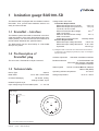
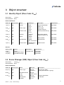
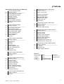
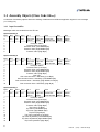
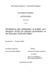
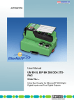
O
P
E
R
A
T
I
N
G
M
A
N
U
A
L
tina10e1
BAG100-SD
Part Number
352-005
352-006
Remark
This Operation Manual is a supplement to the Operating Manual
of the BAG100-S. The standard
RS 232 interface is not active in
the BAG100-SD.
DeviceNet Interface for
the Bayard Alpert Gauge
General Note
The right of alterations in the design and the technical
data is reserved.
The illustrations are not binding.
Contents
1
1.1
1.2
1.3
Page
Ionization gauge BAG100-SD . . . . . . . . . . . 3
DeviceNet-Interface . . . . . . . . . . . . . . . . . . . . 3
Pin Description of DeviceNet plug . . . . . . . . . 3
Technical data . . . . . . . . . . . . . . . . . . . . . . . . 3
2
2.1
2.2
Starting-up of the BAG100-SD . . . . . . . . . . 4
Setting of the baudrate and address . . . . . . . 4
MNS - LED . . . . . . . . . . . . . . . . . . . . . . . . . . 4
3
3.1
3.2
Object Structure . . . . . . . . . . . . . . . . . . . . . 5
Identity Object (Class Code 01hex) . . . . . . . . . 5
Device Manager (DM) Object
(Class Code 64hex) . . . . . . . . . . . . . . . . . . . . 5
3.3
Assembly Objects (Class Code 04hex) . . . . . . 8
3.3.1 Input Assemblies . . . . . . . . . . . . . . . . . . . . . . 8
3.3.2 Output Assemblies . . . . . . . . . . . . . . . . . . . . 9
3.4
Sensor Actuator Controller (SAC) Object
(Class Code 66hex) . . . . . . . . . . . . . . . . . . . 11
3.5
Sensor Pressure
Object (Class Code 67hex) . . . . . . . . . . . . . . 11
3.6
Transform Pressure Object
(Class Code 68hex) . . . . . . . . . . . . . . . . . . . 12
3.7
Discrete Output Point Object
(Class Code 69hex) . . . . . . . . . . . . . . . . . . . 12
3.8
Analog Output Point Object
(Class Code 6Ahex) . . . . . . . . . . . . . . . . . . . 13
4
4.1
4.2
Supported Modes . . . . . . . . . . . . . . . . . . . 14
Bit Strobe . . . . . . . . . . . . . . . . . . . . . . . . . . 14
Change of State . . . . . . . . . . . . . . . . . . . . . 14
5
Format of real values . . . . . . . . . . . . . . . . 15
6
Service at INFICON . . . . . . . . . . . . . . . . . . .16
7
Disposal . . . . . . . . . . . . . . . . . . . . . . . . . . . 16
EEC Declaration of Conformity . . . . . . . . . . . . . . 17
Declaration of Contamination . . . . . . . . . . . . . . . 18
2
tina10e1
(0105)
BAG100-SD.ga
1 Ionization gauge BAG100-SD
The BAG100-SD is equipped with the fieldbus interface
DeviceNet. Thus, process auto-matization devices can
easily be interconnected.
Voltage levels CAN Lines:
Transmitter Requirements
Differential Output level (nominal)
2.0 V p-p
Differential Output level (minimum)
1.5 V p-p
connector, 50 Ohms load
Minimum Recessive Bus voltage
2.0 V 1)
CAN H and CAN L
Maximum Recessive Bus voltage
3.0 V 1)
CAN H and CAN L
Output short circuit protection
internally limited
Receiver Requirements
Differential Input Voltage dominant
0.95 V min
Differential Input Voltage Recessive 0.45 V max
Hysteresis
150 mV typ.
1.1 DeviceNet - Interface
The fieldbus-system DeviceNet is described in the DeviceNet specification of the Open DeviceNet Vendor Association (ODVA). The technical and functional features of
the DeviceNet Standards are specified herein.
The BAG100-SD has the functionality of a DeviceNet
Group 2 Only Slave.
1) Voltages at CAN H and CAN L are referenced to the transceiver
IC ground pin. This voltage (IC ground pin) is app. 0.6 Volt higher
than the V-terminal.
1.2 Pin Description of
DeviceNet plug
Address adjustment
Baudrate selection
This unit uses a "Sealed Micro-Style Connector".
Status signals
1.3 Technical data
Device Type
Generic
Baud Rates
125 k, 250 k, 500 k Baud
I/O-Slave Messaging
Selectable via address switches
3 fixed baudrates and
auto-baud-rate detection selectable
via the address switches
1 bicolor combined Module / Network
Status LED (MNS)
Operating ambient temperature
Storage temperature
0 to 50 °C
- 20 °C to + 80 °C
Bit Strobe, Polling,
Change of State, Cyclic
Isolated Physical Layer
Input voltage range for DeviceNet option
11 - 25 Volt
Key to fig. 1
Pin - no
Function:
–––––––––––––––––––––
1
Drain
2
V+
3
V4
CAN H
5
CAN L
4
1
5
3
2
Fig. 1 Pin out for Micro Style Connectors
tina10e1
(0105)
BAG100-SD.ga
3
2 Starting-up of the BAG100-SD
For starting-up the fieldbus
- the whole system has to be installed electronically.
- the master has to be configurated
- the address of the slaves has to be set
2.1 Setting of the baudrate
and address
Baudrate
Alternatively you can choose between two kinds of
baudrate installations:
Auto - Baud - Rate - Detection
If the unit is switched on during data transfer on the network (minimum: 2 nodes installed with data traffic between these nodes) the unit detects automatically the
installed baudrate on the bus.
Pre-installed baudrate
You can install three baudrates (125 kBaud, 250 kBaud
and 500 kBaud) by using the address switches.
The function of the address switches (Figure 1) is as follows:
Address
Function
––––––––––––––––––––––––––––––––––––––––––––
0 - 64
MAC ID
(Address selection by address switches)
90
Baudrate 125 kBaud
91
Baudrate 250 kBaud
92
Baudrate 500 kBaud
99
Initialisation with default values and autobaudrate detection
How to install the auto baudrate detection
If a fixed baudrate is installed and you want to change
this fixed baudrate to auto baudrate detection, you have
to proceed as follows:
- Switch off the power of the DeviceNet option.
- Set the address switches to the address 99 (initialisation of all values with default values).
- Switch on the power of the DeviceNet option.
The MNS - LED will glow orange.
- Switch off the power of the DeviceNet option.
- Set the address switches to the MAC ID you want the
device to work with.
- Switch on the power of the DeviceNet option.
The MNS - LED will flash green if a communication between the BAG100-SD and an other device takes place.
The installed auto baudrate detection is saved in
EEPROM. After power ON/OFF the unit works with this
installed auto baudrate detection.
2.2 MNS-LED
The MNS LED corresponds to the ODVA standard. The
following additional features were integrated.
LED Colour
Function
––––––––––––––––––––––––––––––––––––––––––––
orange permanent The address switches are set to
one of the possible baudrate settings (90, 91, 92) or to "Initialisation
with default values" (99)
red permanent
Not allowed MAC ID.
How to install a fixed baudrate
- Switch off the power of the DeviceNet option.
- Set the address switches to the address 90, 91 or 92
(depending on the baudrate you want)
- Switch on the power of the DeviceNet option.
The MNS - LED will glow orange.
- Switch off the power of the DeviceNet option.
- Set the address switches to the MAC ID you want the
device to work with
- Switch on the power of the DeviceNet option.
The MNS - LED will flash green or alternatively
red/green if a communication between the BAG100-SD
and an other device takes place.
The installed baudrate is saved in EEPROM. After power
ON/OFF the unit works with this installed baudrate.
4
tina10e1
(0105)
BAG100-SD.ga
3 Object structure
3.1 Identity Object (Class Code 01hex)
Class Code:
1 (01hex)
Class Attributes: None
Instance Attributes
Attribut ID
Access Rule
Name
Data/Type
Description
Spezification
–––––––––––––––––––––––––––––––––––––––––––––––––––––––––––––––––––––––––––––––––––––––––––––
1 (01hex)
get
Vendor
UINT
Vendor Identification
DeviceNet
90 00
Value: 144
2 (02hex)
get
Device Type
UINT
00 00
Device type
(Generic Device)
DeviceNet
3 (03hex)
get
Product Code
UINT
01 00
Vendor productcode (1)
DeviceNet
4 (04hex)
get
Revision
DeviceNet software
version number (1.0)
DeviceNet
5 (05hex)
get
Status
STRUCT
01 00
WORD
01 00
Device Status
DeviceNet
6 (06hex)
get
Serial Number
UDINT
z.B. 44 00 00 00
Serial Number
DeviceNet
7 (07hex)
get
Product Name
SHORT String
(ITR100-D)
Product Name
DeviceNet
Services
Service Code
Name
Description
Spezification
––––––––––––––––––––––––––––––––––––––––––––––––––––––––––––––––––
5 (05hex)
Reset
complete reset
DeviceNet
14 (0Ehex)
Get Attribute Single
DeviceNet
16 (10hex)
Set Attribute Single
DeviceNet
3.2 Device Manager (DM) Object (Class Code 64hex)
Class Code:
100 (64hex)
Class Attributes: None
Instance Attributes
Attribut ID
Access Rule
Name
Data/Type
Description
–––––––––––––––––––––––––––––––––––––––––––––––––––––––––––––––––––––––––––––––––––––––––––––
49 (31hex)
get
Device Type
String [4]
Device type SEMI
48 43 49 47
HCIG (Hot cathode ion gauge)
50 (32hex)
get
Standard Revision
Level
String [5]
44 52 41 46 54
51 (33hex)
get
Device
Manufacturer
Identifier
String [7]
4c 45 59 42
4f 4c 44
tina10e1
(0105)
BAG100-SD.ga
Vendor identification
”INFICON”
5
Attribut ID
Access Rule
Name
Data/Type
Description
–––––––––––––––––––––––––––––––––––––––––––––––––––––––––––––––––––––––––––––––––––––––––––––
52 (34hex)
get
Manufacturer
String [8]
Catalog Number BAG100-SD
Model Number
49 54 52 31 30
30 2d 44
53 (35hex)
get
Firmware Revision
Level
String [5]
31 2e 31 30 30
Software version 1.100
54 (36hex)
get
Hardware
Revision Level
String [5]
31 2e 31 30 30
Hardware Version 1.100
55 (37hex)
get
Serial Number
Electronic
String [5]
56 (38hex)
get
Device
Configuration
String [8]
49 45 31 30 30
20 4b 46
57 (39hex)
get
Device Status
UINT
Device status :
1 = Initialising
2 = Idle (emmisson off)
4 = Executing (emmission on)
58 (3Ahex)
get / set
Reporting Mode
BYTE
Polling, Bit Strobe = 6
COS/Cyclic = 0
60 (3Chex)
get
Exception Status
BYTE
Bit
Bit
Bit
Bit
Bit
Bit
Bit
Bit
Exception Detail
Alarm
Array of 9 Byte
Byte
Byte
Byte
Byte
Byte
Byte
0:
Length 2 Alarm / Dev. Common
1 / 2: see below
3:
Length 2 Alarm/Dev. spec.
4 / 5 : see below
6:
Length 2 Alarm / Manuf. spec.
7 / 8: see below
Byte
Byte
Byte
Byte
Byte
Byte
0:
Length 2 Warning Dev. Com.
1 / 2: see below
3:
Length 2 Warning Dev. spec.
4 / 5 : see below
6:
Length 2 Warning Manuf. spec.
7 / 8: see below
61 (3Dhex)
62 (3Ehex)
get
Exception Detail
Warning
Array of 9 Byte
77 (4Dhex)
get
Serial Number
Sensor
String [5]
30 30 30 33 36
6
0
1
2
3
4
5
6
7
= Alarm / Device Common
=Alarm / Device specific
= Alarm / Manufacturer specific
= reserved
= Warning / Device Common
= Warning / Device specific
= Warning / Manufacturer specific
= 1 (Expanded Mode)
tina10e1
(0105)
BAG100-SD.ga
Detail Attribute Values Alarm and Warning:
Common Exception Detail
bit Detail [0] = Byte 1
–––––––––––––––––––––––––––––––––
0
internal diagnostic exception
1
microprocessor exception
2
EPROM exception
3
EEPROM exception
4
RAM exception
5
communications exception
6
internal real-time exception
7
reserved
Common Exception Detail
bit Detail [1] = Byte 2
–––––––––––––––––––––––––––––––––
0
power supply overcurrent
1
reserved power supply
2
power supply output voltage
3
power supply input voltage
4
routine maintanance due
5
notify manufacturer
6
reset exception
7
reserved
Device Exception Detail Alarm
bit Detail [0] = Byte 4
–––––––––––––––––––––––––––––––––
0
pressure fault
1
reserved
2
reserved
3
calibration fault
4
sensor 1(filament) fault
5
sensor 2 (filament) fault
6
degas fault
7
temperature fault
Device Exception Detail Alarm
Detail [1] = Byte 5
–––––––––––––––––––––––––––––––––
reserved
Device Exception Detail Warning
bit Detail [0] = Byte 4
–––––––––––––––––––––––––––––––––
0
pressure invalid
1
pressure overrange
2
pressure underrange
3
calibration warning
4
sensor 1(filament) warning
5
sensor 2 (filament) warning
6
degas warning
7
temperature warning
Manufacturer Exception Detail Alarm
bit Detail [0] = Byte 7
–––––––––––––––––––––––––––––––––
0
Sensor 1 and 2 fault
1
2
Emission current failure
3
Anode voltage failure
4
Kathode voltage failure
5
Temperature too high
6
Pressure too high
7
Degas failure
Manufacturer Exception Detail Alarm
bit Detail [1] = Byte 8
–––––––––––––––––––––––––––––––––––––––
0
heating too high
4
Cathode voltage too high
Manufacturer Exception Detail Warning
bit Detail [0] = Byte 7
–––––––––––––––––––––––––––––––––––––––
0
filament 1 broken
1
filament 2 broken
2
emission current deviations
3
Anode voltage deviations
4
Cathode voltage deviations
5
Temperature too high
6
EEPROM Device memory lost
7
EEPROM Sensor memory lost
Manufacturer Exception Detail Warning
bit Detail [1] = Byte 8
–––––––––––––––––––––––––––––––––––––––
0
no emission
1
heating too high
2
Trigger setting unallowed
Services
Service Code Name
Description
––––––––––––––––––––––––––––––––––––––––––––
5 (05hex)
Reset
Complete reset
Get Attribute Single
14 (0Ehex)
16 (10hex)
Set Attribute Single
Device Exception Detail Warning
Detail [1] = Byte 5
–––––––––––––––––––––––––––––––––
reserved
tina10e1
(0105)
BAG100-SD.ga
7
3.3 Assembly Objects (Class Code 04hex)
A collection of assembly objects allows the sending of attributes from different application objects in one message
(i.e.: Polling I/O).
3.3.1 Input Assemblies
Messages which are sended from the ITR 100.
Input Assembly 5
Byte
Bit 7 Bit 6 Bit 5 Bit 4
Bit 3
Bit 2
Bit 1
Bit 0
–––––––––––––––––––––––––––––––––––––––––––––––––––––––––––––––––––––––––
0
res
res
res
Trip Point Trip Point Active FilaDegas
Sensor
Source
Status
ment Number Status
Status
–––––––––––––––––––––––––––––––––––––––––––––––––––––––––––––––––––––––––
1
Exception Status
2
Pressure value (Low Byte)
3
Pressure value (Low Middle Byte)
4
Pressure value (High Middle Byte)
5
Pressure value (High Byte)
Input Assembly 6
Byte
Bit 7 Bit 6 Bit 5 Bit 4
Bit 3
Bit 2
Bit 1
Bit 0
–––––––––––––––––––––––––––––––––––––––––––––––––––––––––––––––––––––––––
0
res
res
res
Trip Point Trip Point Active FilaDegas
Sensor
Source
Status
ment Number Status
Status
–––––––––––––––––––––––––––––––––––––––––––––––––––––––––––––––––––––––––
1
Exception Status
2
Pressure value (Low Byte)
3
Pressure value (Low Middle Byte)
4
Pressure value (High Middle Byte)
5
Pressure value (High Byte)
6
Gas Type
7
Gas correction factor / Sensitivity (Low Byte)
8
Gas correction factor / Sensitivity (Low Middle Byte)
9
Gas correction factor / Sensitivity (High Middle Low Byte)
10
Gas correction factor / Sensitivity (High Byte)
Input Assembly 7
Byte
Bit 7 Bit 6 Bit 5 Bit 4
Bit 3
Bit 2
Bit 1
Bit 0
–––––––––––––––––––––––––––––––––––––––––––––––––––––––––––––––––––––––––
0
res
res
res
Trip Point Trip Point Active FilaDegas
Sensor
Source
Status
ment Number Status
Status
–––––––––––––––––––––––––––––––––––––––––––––––––––––––––––––––––––––––––
1
Exception Status
2
Pressure value (Low Byte)
3
Pressure value (Low Middle Byte)
4
Pressure value (High Middle Byte)
5
Pressure value (High Byte)
6
Trip Point (Low Byte)
7
Trip Point (Low Middle Byte)
8
Trip Point (High Middle Byte)
9
Trip Point (High Byte)
10
Trip Point Hysteresis (Low Byte)
11
Trip Point Hysteresis (Low Middle Byte)
12
Trip Point Hysteresis (High Middle Byte)
13
Trip Point Hysteresis (High Byte)
8
tina10e1
(0105)
BAG100-SD.ga
Input Assembly 8
Byte
Bit 7 Bit 6 Bit 5 Bit 4
Bit 3
Bit 2
Bit 1
Bit 0
–––––––––––––––––––––––––––––––––––––––––––––––––––––––––––––––––––––––––
0
res
res
res
Trip Point Trip Point Active FilaDegas
Sensor
Source
Status
ment Number Status
Status
–––––––––––––––––––––––––––––––––––––––––––––––––––––––––––––––––––––––––
1
Exception Status
2
Pressure value (Low Byte)
3
Pressure value (Low Middle Byte)
4
Pressure value (High Middle Byte)
5
Pressure value (High Byte)
6
Gas Type
7
Gas correction factor / Sensitivity (Low Byte)
8
Gas correction factor / Sensitivity (Low Middle Byte)
9
Gas correction factor / Sensitivity (High Middle Low Byte)
10
Gas correction factor / Sensitivity (High Byte)
11
Trip Point (Low Byte)
12
Trip Point (Low Middle Byte)
13
Trip Point (High Middle Byte)
14
Trip Point (High Byte)
15
Trip Point Hysteresis (Low Byte)
16
Trip Point Hysteresis (Low Middle Byte)
17
Trip Point Hysteresis (High Middle Byte)
18
Trip Point Hysteresis (High Byte)
Input Assembly 9
Byte
Bit 7 Bit 6 Bit 5 Bit 4
Bit 3
Bit 2
Bit 1
Bit 0
–––––––––––––––––––––––––––––––––––––––––––––––––––––––––––––––––––––––––
0
Pressure value (Low Byte)
1
Pressure value (Low Middle Byte)
2
Pressure value (High Middle Byte)
3
Pressure value (High Byte)
Input Assembly 10
Byte
Bit 7 Bit 6 Bit 5 Bit 4
Bit 3
Bit 2
Bit 1
Bit 0
–––––––––––––––––––––––––––––––––––––––––––––––––––––––––––––––––––––––––
0
Exception Status
3.3.2 Output Assemblies
Messages which are sended to the ITR 100.
Output Assembly 1
Byte
Bit 7 Bit 6 Bit 5 Bit 4 Bit 3 Bit 2
Bit 1
Bit 0
––––––––––––––––––––––––––––––––––––––––––––––––––––––––––––––––––––
0
res
res
res
res
res
Trip Point Degas
Emmission
Control
Status
ON / OFF
Source
––––––––––––––––––––––––––––––––––––––––––––––––––––––––––––––––––––
tina10e1
(0105)
BAG100-SD.ga
9
Output Assembly 2
Byte
Bit 7 Bit 6 Bit 5 Bit 4 Bit 3 Bit 2
Bit 1
Bit 0
––––––––––––––––––––––––––––––––––––––––––––––––––––––––––––––––––––
0
res
res
res
res
res
Trip Point Degas
Emmission
Source
Status
ON / OFF
––––––––––––––––––––––––––––––––––––––––––––––––––––––––––––––––––––
1
Gas Type
2
Gas correction factor / Sensitivity (Low Byte)
3
Gas correction factor / Sensitivity (Low Middle Byte)
4
Gas correction factor / Sensitivity (High Middle Low Byte)
5
Gas correction factor / Sensitivity (High Byte)
Output Assembly 3
Byte
Bit 7 Bit 6 Bit 5 Bit 4 Bit 3 Bit 2
Bit 1
Bit 0
––––––––––––––––––––––––––––––––––––––––––––––––––––––––––––––––––––
0
res
res
res
res
res
Trip Point Degas
Emmission
Source
Status
ON / OFF
––––––––––––––––––––––––––––––––––––––––––––––––––––––––––––––––––––
1
Trip Point (Low Byte)
2
Trip Point (Low Middle Byte)
3
Trip Point (High Middle Byte)
4
Trip Point (High Byte)
5
Trip Point Hysteresis (Low Byte)
6
Trip Point Hysteresis (Low Middle Byte)
7
Trip Point Hysteresis (High Middle Byte)
8
Trip Point Hysteresis (High Byte)
Output Assembly 4
Byte
Bit 7 Bit 6 Bit 5 Bit 4 Bit 3 Bit 2
Bit 1
Bit 0
––––––––––––––––––––––––––––––––––––––––––––––––––––––––––––––––––––
0
res
res
res
res
res
Trip Point Degas
Emmission
Source
Status
ON / OFF
––––––––––––––––––––––––––––––––––––––––––––––––––––––––––––––––––––
1
Gas Type
2
Gas correction factor / Sensitivity (Low Byte)
3
Gas correction factor / Sensitivity (Low Middle Byte)
4
Gas correction factor / Sensitivity (High Middle Low Byte)
5
Gas correction factor / Sensitivity (High Byte)
6
Trip Point (Low Byte)
7
Trip Point (Low Middle Byte)
8
Trip Point (High Middle Byte)
9
Trip Point (High Byte)
10
Trip Point Hysteresis (Low Byte)
11
Trip Point Hysteresis (Low Middle Byte)
12
Trip Point Hysteresis (High Middle Byte)
13
Trip Point Hysteresis (High Byte)
10
tina10e1
(0105)
BAG100-SD.ga
3.4 Sensor Actuator Controller (SAC)
Objekt (Class Code 66hex)
Class Code:
102 (66hex)
Service Code
Name
Description
––––––––––––––––––––––––––––––––––––––––––––––––
Reset
complete reset
5 (05hex)
75 (4Bhex)
Sensor State
Measurement on/off
(emission on/off)
The service "Sensor State" switches the emission on and off. Measurement values are stored in the ”Pressure value”
attribute of the Transform Pressure object.
Parameter Name
––––––––––––––––––––––––
0
Emisson OFF
1
Emission ON
3.5 Sensor Pressure Object (Class Code 67hex)
The Sensor Pressure Object contains characteristics and behavior of the BAG100. This object is specified as a SACObject. All defined services for SAC-Objects are valid.
Class Code:
103 (67hex)
Class Attributes: None
Instance Attributes
Attribut ID
Access Rule
Name
Data/Type
Description
–––––––––––––––––––––––––––––––––––––––––––––––––––––––––––––––––––––––––––––––––––––––––––––
3 (03hex)
get
Sensor Status
BOOL
Sensor Status (Gauge ON / Gauge OFF)
6 (06hex)
get / set
Degas State
BOOL
10 (0Ahex)
get
Emission Current
BYTE
14 (0Ehex)
get
Active Filament
Number
BOOL
100 (64hex)
get / set
Emission
ON / OFF
BOOL
Degas Status ON / OFF
0 = Filament 1
1 = Filament 2
Comment to attribute 6 Degas State:
- If degas ON = 1 (Attribute 6) is set, the emission will be switched on, independingly from the value of Attribute 100
(Emission ON/OFF)
- After the automatic Degas switch off (after 3 minutes), the emission will still remain. Degas OFF and Degas ON has
to be set to restart the Degas mode.
Services
Service Code
Name
Description
–––––––––––––––––––––––––––––––––––––––––––––––––––
5 (05hex)
Reset
Complete reset
14 (0Ehex)
Get Attribute Single
16 (10hex)
Set Attribute Single
50 (32hex)
Degas
Degas ON / OFF
The Service Degas switches Degas On or Off:
Parameter
Name
–––––––––––––––––––––
0
Degas OFF
1
Degas ON
tina10e1
(0105)
BAG100-SD.ga
11
3.6 Transform Pressure Object (Class Code 68hex)
Class Code:
104 (68hex)
Class Attributes: None
Instance Attributes
Attribut ID
Access Rule
Name
Data/Type
Description
Spezification
–––––––––––––––––––––––––––––––––––––––––––––––––––––––––––––––––––––––––––––––––––––––––––––
get
Pressure Value
REAL
Pressure Value
SEMI
1 (01hex)
3 (03hex)
get / set
Pressure Units
BYTE
0 = mbar default
SEMI
1 = Torr
4 (04hex)
get / set
Gas Type
BYTE
4 = Argon
7 = H2
13 = N2 default
>=187 Gas correction
factor / Sensitivity valid
SEMI
5 (05hex)
get / set
Gas correction
factor / Sensitivity
REAL
Gas factor
SEMI
Comment to attribute 5 gas correction factor / Sensitivity:
For a mixture of different gases you could specify a special factor. The used value corresponds to the relativ probability of the ioniozation. The value for nitrogen is:
relativ probability of the ioniozation = 1.
For this relativ probability of the ioniozation you have to use the value 5000 for the sensitivity. Other values could be
calculated by the formula:
sensitivity = relativ probability of the ioniozation * 5000
If you want to work with a user defined sensitivity, the gas type has to be set to values > = 187.
Services
Service Code Name
Description
––––––––––––––––––––––––––––––––––––––––––––––––––––––––––––––––––
14 (0Ehex)
Get Attribute Single
16 (10hex)
Set Attribute Single
75 (4Bhex)
Select Programmed Gas Type
4 = Argon, 7 = H2, 13 = N2
3.7 Discrete Output Point Object (Class Code 69hex)
Class Code:
105 (69hex)
Class Attributes: None
Instance Attributes
Attribut ID
Access Rule
Name
Data/Type Description
–––––––––––––––––––––––––––––––––––––––––––––––––––––––––––––––––––––––––––––––––––––––––––––
3 (03hex)
get
Trip Point Status
BOOL
0 ↔ relay deactivated
100 (64hex)
get / ( set)
Trip Point
REAL
102 (66hex)
ge t/ (set)
Trip Point Hysteresis
REAL
103 (67hex)
get / (set)
Trip Pointupper Value
REAL
104 (68hex)
get / (set)
Trip Pointlower Value
REAL
105 (69hex)
get / set
Trip Point
Control Source
BOOL
12
Hysteresis in %
0 ↔ Poti; 1 ↔ DeviceNet
You can decide whether the trip point is set by the
potentiometer or by DeviceNet.
tina10e1
(0105)
BAG100-SD.ga
Services
Service Code Name
Description
Specification
–––––––––––––––––––––––––––––––––––––––––––––––––––––––––––––
14 (0Ehex)
Get Attribute Single
DeviceNet
16 (10hex)
Set Attribute Single
DeviceNet
Explanation to attributes 100 - 104
It is possible to set the trip point by the two values
"trip point" and "trip point hysteresis"
or by
"trip point lower value " and "trip point upper value".
relays status
relays
deactivated
relays
activated
trip point
upper value
trip point
lower value
pressure
trip point
trip point hysteresis
Fig. 2 Relay status activated by trip points
If the pressure decreases under the trip point (trip point lower value) the relay gets activated,
if the pressure increases over the trip point upper value (trip point + hysteresis) the relay gets deactivated.
The two modes
- trip point upper value / trip point lower value or
- trip point / trip point hysteresis can be used alternatively.
3.8 Analog Output Point Object (Class Code 6Ahex)
Class Code:
106 (6Ahex)
Class Attributes: None
Instance Attributes
Attribut ID
Access Rule
Name
Data/Type
Description
–––––––––––––––––––––––––––––––––––––––––––––––––––––––––––––––––––––––––––––––––––––––––––––
Analog Output Mode BYTE
() ↔ log; 1 ↔ lin („C“)
101 (65hex) get / set
102 (66hex)
get / set
Analog Output Mode
Extension
BYTE
A, 2, 3, 4, 5, 6, 7, 8, 9 = linear
D = log.
C = Mantissa and Exponent separate
0, 1, B, E, F = not used
(See description in the user manual of the
BAG100)
Services
Service Code Name
––––––––––––––––––––––––––––––––
14 (0Ehex)
Get Attribute Single
16 (10hex)
Set Attribute Single
tina10e1
(0105)
BAG100-SD.ga
13
4 Supported Modes
The BAG100-SD acts as a "DeviceNet Group Two Only Slave". It supports the modes Polling, Bit-Strobe, Change of
State/ Cyclic and explicit messagges.
Attention
Interscan delay: 25 ms
4.1 Bit Strobe
The emission may be switched on and off by the Bit-Strobe application.
Bit-Strobe Bit = 1 → emission on
Bit-Strobe Bit = 0 → emission off
The Bit-Strobe response message is Input Assembly 5.
After the the bit strobe message the returned measurement value is not the actual value. You will receive the correct
value after several bit strobe commands because of the transient behaviour of the BAG100 (see user manual
BAG100).
4.2 Change of State
Connection Object Instance Attribute
(Class 5 / Instance 4/ Attribut 100)
Attribut ID
Access Rule
Name
Data/Type
Description
––––––––––––––––––––––––––––––––––––––––––––––––––––––––––––––––––
100 (65hex) get / set
Pressure Change
BYTE
see below
Pressure Change
The attribute describes the deviation in percent of the measurement value which will result in a COS message on the
bus. Possible values for "Pressure Change": 1 - 100 %.
14
tina10e1
(0105)
BAG100-SD.ga
5 Format of real values
According to the IEEE-754 standard real values are stored in floating point format. The floating point values are transmitted according to the following format:
Byte
2
3
4
5
–––––––––––––––––––––––––––––––––––––––––––––––––––––––––––––––––––––––––
Content
SEEE EEEE
EMMM MMMM
MMMM MMMM
MMMM MMMM
S means: Sign Bit, which means 1 = negative, 0 = positive
E means: Two-complement exponents with offset 127
M means: 23 bit mantissa. The most significant bit is always 1 and is, therefore, not stored.
Example:
The value
-12.5
Byte number of
Byte 3:
Byte 2:
Byte 1:
Byte 0:
the floating
C1 hex
48 hex
00 hex
00 hex
point value
–––––––––––––––––––––––––––––––––––––––––––––––––––––––––––––––––––––––––
Content
SEEE EEEE EMMM MMMM
MMMM MMMM
MMMM MMMM
Content in this
example
1100 0001
binary
0100 1000
binary
0000 0000
binary
0000 0000
binary
Sign bit:
The bit S in this example is 1. That means the sign bit of the whole value (or of the mantissa) is „minus“.
Exponent:
The EEEE EEEE have the value: 1000 0010 binary. This value converted in decimal it is: 130 decimal. This value has
the offset 127. So the exponent is: 130 - 127 = 3
Mantissa:
Because the mantissa is normalized the most significant bit has the value 1, the next bit has the value 0.5, the next bit
has the value 0.25.
Bit number
bit 24 (MSB)
bit 23
bit 22
bit 21
bit 20
bit 19
bit 18
bit 17
and so on
Value of the bit, if the bit is set to 1
1
0.5
0.25
0.125
0.0625
0.03125
0.015625
0.0078125
The
MMM MMMM MMMM MMMM MMMM MMMM (23bit) have the value 100 1000 0000 0000 0000 0000. The
most significant bit (MSB) is always 1 (and not stored). You have to implement this most significant bit.
So the value of the mantisse is: 1100 1000
Bit
Bit
Bit
Bit
number
24 is set to 1 →
23 is set to 1 →
20 is set to 1 →
0000 0000
0000 0000 (binary).
Value
1
+ 0.5
+ 0.0625
So the mantissa has the value 1.5625
Whole Value:
The whole value is: -1.5625·23 = -12.5
tina10e1
(0105)
BAG100-SD.ga
15
6 Service at INFICON
7 Disposal
Warning
Warning
Contaminated products (e.g. radioactive, toxic, caustic or microbiological
hazard) can be detrimental to health and
environment.
Products returned to INFICON should preferably be free
of harmful substances. Adhere to the forwarding regulations of all involved countries and forwarding companies
and enclose a duly completed declaration of contamination (see Annex).
Products that are not clearly declared as „free of harmful
substances“ are decontaminated at the expense of the
customer.
Products not accompanied by a duly completed declaration of contamination are returned to the sender at his
own expense.
Contaminated parts
Contaminated parts can be detrimental
to health and environment.
Before beginning to work, find out whether any parts are
contaminated. Adhere to the relevant regulations and
take the necessary precautions when handlinmg contaminated parts.
Warning
Substance detrimental to the environment
Products or parts thereof (mechanical
and electric components, operating
fluids etc.) can be detrimental to the
environment.
Dispose of such substance in accordance with the relevant local regulations.
Separating the components
After disassembling the product, separate its components according to the following criteria:
Contaminated components
Contaminated components (radioactive, toxic, caustic
or biological hazard etc.) must be decontaminated in
accordance with the relevant national regulations,
separated according to their materials, and disposed
of.
Other components
Such components must be separated according to
their materials and recycled.
16
tina10e1
(0105)
BAG100-SD.ga
EEC Declaration of Conformity
as defined by the Directive relating to machinery
98/37/EG, Appendix IIb.
We -INFICON - herewith declare that the products defined
below meet the basic requirements regarding safety and
health of the relevant EEC directives by design, type and
the versions which are brought in to circulation by us.
We also declare that the equipment mentioned below
complies with the provisions of the Directive relating to
electrical equipment designed for use within certain voltage limits 73/23/ EEC and the Directive relating to electromagnetic compatibility 89/336/EEC.
Standards
Harmonized and international / national standards and
specifications:
•
EN 61010 - 1 - 1993
•
EN 50081 - 1 - 1992
•
EN 50082 - 2 - 1995
•
VDE 0411 Teil 1 / 03.94
•
VDE 0839 Teil 81 - 1 / 03.93
•
VDE 0839 Teil 82 - 2 / 02.96
Product:
DeviceNet Interface of the BAG100-SD
Part Number
352-005
352-006
Balzers, 4 May 2001
Balzers, 4 May 2001
—————————————————————
Hannes Fischer, Product Manager
—————————————————————
Dr. Georg Sele, Technical Support Manager;
Quality Representative
tina10e1
(0105)
BAG100-SD.ga
17
Declaration of Contamination
18
tina10e1
(0105)
BAG100-SD.ga
tina10e1
(0105)
BAG100-SD.ga
19
INFICON LIMITED:
FL-9496 Balzers, Principality of Liechtenstein
Phone: +423 388 3111 Fax: +423 388 3700 www.inficon.com
UNITED STATES
FRANCE
GERMANY
LIECHTENSTEIN
UNITED KINGDOM
CHINA
JAPAN
KOREA
SINGAPORE
TAIWAN
Due to INFICONÕs continuing program of product improvements, specifications are subject to change without notice.
Vi s i t o u r w e b s i t e f o r c o n t a c t i n f o r m a t i o n a n d o t h e r s a l e s o ff i c e s w o r l d w i d e . w w w. i n f i c o n . c o m
tina10e1
(0105)
BAG100-SD.ga