1
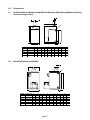
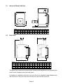
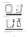
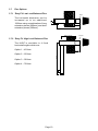
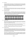
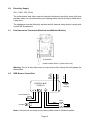
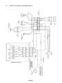
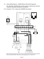
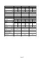
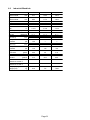
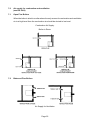
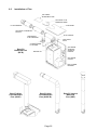
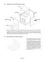
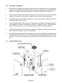
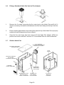
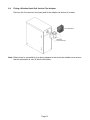
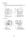
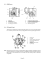
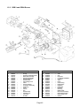
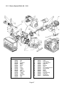
INSTALLATION & SERVICING
MANUAL FOR
50/70 – 70/90 – 90/120 – 120/150 – 150/200
BLUEBIRD BOILERHOUSE MODELS,
GOLDBIRD KITCHEN MODELS
& WHITEBIRD UTILITY ROOM MODELS
50/90
FRONT SERVICING BOILERS
GOLDBIRD KITCHEN MODEL
WHITEBIRD UTILITY ROOM MODEL
200/250
BLUEBIRD BOILERHOUSE MODEL
50/70 – 70/90
WHITEBIRD UTILITY ROOM SYSTEM BOILER
50/70 – 70/90 – 90/120 – 120/150 – 150/200
KABIN PAK EXTERNAL BOILERHOUSE MODULES
50/90
SLIMLINE KABIN PAK
EXTERNAL BOILERHOUSE MODULE
50/70 – 70/90
KABIN PAK BACK OUTLET
EXTERNAL BOILERHOUSE MODULES
300 – 400 – 500
CONVENTIONAL FLUED
INDUSTRIAL BLUEBIRD BOILERHOUSE MODELS
LEAVE THESE INSTRUCTIONS WITH THE END USER
ISSUE 6.2
JAN ’04
COMMISSIONING
*THIS APPLIANCE MUST
BE COMMISSIONED
*Failure to commission the boiler will invalidate the warranty.
After commissioning ensure that the pre-paid
warranty registration card is completed
and returned.
SERVICING
To ensure continued reliable operation and fuel
economy it is recommended that the boiler is
serviced annually by an OFTEC registered
technician.
NI CUSTOMERS ONLY
Warmflow Engineering Service division (NI)
provides an excellent back-up service, operating
a team of OFTEC trained engineers who can
meet all the servicing, commissioning and
breakdown requirements for your appliance.
Telephone
0870 240 6532
Fax: 028 9262 2827
E-mail: [email protected]
Contents
Page
1.0
User Instructions ............................................................................................................................................................ 2
1.1
Goldbird Models ................................................................................................................................................. 2
1.2
Bluebird, Kabin Pak and Whitebird Models ........................................................................................................ 2
1.3
Servicing ............................................................................................................................................................ 2
1.4
Components 50/70, 70/90, 90/120, 120/150, 150/200, 200/250 ........................................................................ 2
1.5
System Boiler ..................................................................................................................................................... 3
1.6
Components 50/90 Front Servicing Boiler
1.7
Components 300, 400 & 500 Industrial Boilers .................................................................................................. 4
1.8
Baffles ................................................................................................................................................................ 5
2.0
Introduction ..................................................................................................................................................................... 6
2.1
General Requirements ....................................................................................................................................... 6
3.0
Dimensions ..................................................................................................................................................................... 7
3.1
Goldbird & Whitebird Models ............................................................................................................................. 7
3.2
Bluebird Models ................................................................................................................................................. 7
3.3
Industrial Bluebird Models .................................................................................................................................. 8
3.4
Kabin Pak ........................................................................................................................................................... 8
3.5
Kabin Pak Back Outlet ....................................................................................................................................... 9
3.6
Slimline Kabin Pak ............................................................................................................................................. 9
3.7
Flue Options ..................................................................................................................................................... 10
4.0
Installation ..................................................................................................................................................................... 12
4.1
Service Access ................................................................................................................................................. 12
4.2
Hearth .............................................................................................................................................................. 12
4.3
Heating System ................................................................................................................................................ 12
4.4
Sealed System ................................................................................................................................................. 12
4.5
Air Vents ........................................................................................................................................................... 13
4.6
Drain Cock ....................................................................................................................................................... 13
4.7
Expansion Vessels ........................................................................................................................................... 13
4.8
System Filling ................................................................................................................................................... 13
4.9
System Pressure .............................................................................................................................................. 13
5.0
Electricity Supply ......................................................................................................................................................... 14
5.1
Dual Thermostat ............................................................................................................................................... 14
5.2
RDB Control Box .............................................................................................................................................. 14
5.3
Control Panel Wiring (Goldbirds) ..................................................................................................................... 15
5.4
R40 Control Box ............................................................................................................................................... 16
5.5
Installation of Optional Programmer ................................................................................................................. 16
5.6
System Wiring Diagrams (Goldbirds) ............................................................................................................... 17
6.0
Technical Data ............................................................................................................................................................... 19
6.1
Goldbird, Whitebird & Bluebird ......................................................................................................................... 19
6.2
Industrial Bluebirds ........................................................................................................................................... 21
7.0
Air Supply ...................................................................................................................................................................... 22
7.1
Open Flue Boilers ............................................................................................................................................ 22
7.2
Balanced Flue Boilers ...................................................................................................................................... 22
8.0
Flues
......................................................................................................................................................................... 23
8.1
Conventional Flues .......................................................................................................................................... 23
8.2
Low Level Flues ............................................................................................................................................... 23
8.3
Installation of Flues .......................................................................................................................................... 25
9.0
Installation of Boilers ................................................................................................................................................... 27
9.1
120/150 & 150/200 White Casings ................................................................................................................... 27
9.2
Industrial Bluebird Casings .............................................................................................................................. 27
9.3
Industrial Firebrick ............................................................................................................................................ 27
9.4
Kabin Pak Installations ..................................................................................................................................... 29
9.5
Standard Kabin Paks ....................................................................................................................................... 30
9.6
Kabin Pak Vertical Flue Adaptor ....................................................................................................................... 30
9.7
Slimline Kabin Pak ........................................................................................................................................... 31
9.8
Slimline Kabin Pak Vertical Flue Adaptor ......................................................................................................... 31
10.0
Oil Supply ...................................................................................................................................................................... 32
10.1
One Pipe System ............................................................................................................................................. 32
10.2
Two Pipe System ............................................................................................................................................. 33
10.3
Deaerator System ............................................................................................................................................ 33
10.4
One Pipe Lift .................................................................................................................................................... 34
11.0
Burners ......................................................................................................................................................................... 35
11.1
RDB Burner ...................................................................................................................................................... 35
11.2
G10 Burner ....................................................................................................................................................... 35
11.3
G20S Burner .................................................................................................................................................... 36
11.4
Oil Supply ......................................................................................................................................................... 36
11.5
Air Damper Adjustment .................................................................................................................................... 37
11.6
Electrode Setting .............................................................................................................................................. 37
11.7
Burner Start-up Cycle ....................................................................................................................................... 37
12.0
Servicing & Commissioning ........................................................................................................................................ 38
12.1
Commissioning ................................................................................................................................................. 38
12.2
Servicing .......................................................................................................................................................... 38
13.0
User Instructions – Horstmann 626 Internal Programmer ........................................................................................ 39
14.0
Fault Finding ................................................................................................................................................................. 44
15.0
Spares ......................................................................................................................................................................... 45
15.1
RDB Burners 1 & 2 ........................................................................................................................................... 45
15.2
RDB 3 & 4 Burners ........................................................................................................................................... 46
15.3
R40 G10 Burner ............................................................................................................................................... 47
15.4
R40 G20S Burner ............................................................................................................................................. 48
15.5
Boiler Parts List ................................................................................................................................................ 49
Page 1
1.0 User Instructions
1.1
Goldbird Models
Thermostat Control
The recommended minimum thermostat setting is 65°C. Below this ‘cold water corrosion’
is likely to occur which can reduce the life of the heat exchanger and is not covered by
the boiler warranty. The boiler thermostat is adjustable from 52°C to 88°C.
Mains Indicator
The green mains lamp will be lit when there is power to the control box.
H/L Reset
The yellow H/L reset lamp will be lit when the boiler has overheated and tripped the
high limit thermostat, which then needs to be manually reset. If the high limit thermostat
continues to trip, contact Warmflow or your service engineer/technician. The manual
reset thermostat has a cut out point of 110°C.
Lock-Out
The red lock out lamp will be lit when the burner has failed to fire and can be reset by
pressing the illuminated red reset button on the burner control box.
1.2
Bluebird, Kabin Pak and Whitebird Models
The recommended minimum thermostat setting is 65°C (thermostat setting 1). If the
high limit thermostat operates it may be reset by removing the reset cover and pressing
the reset button. If the burner goes to lockout it can be reset by pressing the illuminated
red reset button on the burner control box. Combustible material must not be placed
on top of the boilerhouse models or on top of the burner cover as the temperature of
certain exposed components can occasionally reach 70°C. The boiler thermostat is
adjustable from 60°C to 90°C and the manual reset limit thermostat has a set point of
110°C.
1.3
Servicing
It is recommended that the boiler is serviced annually by an OFTEC registered engineer.
WARNING: No adjustments to externally situated boilers should be made where wet
weather conditions prevail. In such conditions there may be a risk of ingress of water
into the appliance, which could lead to component failure or electrocution.
1.4
Components – 50/70, 70/90, 90/120, 120/150, 150/200, 200/250
TOP LID
THERMOSTAT
POCKET
BOILER
CASING
FLUE
FLUE
BOILER
THERMOSTAT
CONTROL
TOP LID
LIMIT THERMOSTAT
MANUAL RESET
BUTTON COVER
BOILER
THERMOSTAT
CONTROL
LIMIT THERMOSTAT
RESET BUTTON COVER
BAFFLES
BAFFLES
BOILER CASING
BURNER
LOCKOUT LAMP
& RESET BUTTON
BURNER COVER
BURNER
LOCKOUT LAMP
& RESET BUTTON
BURNER COVER
BASE INSULATION
BASE INSULATION
Bluebird
Goldbird/Whitebird
Page 2
1.5
System Boiler
1.5.1 Components
1
9
2
10
3
11
12
4
13
5
14
6
15
16
7
17
8
18
19
1
Flue
2
System Pressure Gauge
3
Spare BSP Connection (x2)
4
Boiler Limit Thermostat
5
Thermostat Pocket
6
12L Expansion Vessel
7
Heating Return (x2) 1” BSP
8
Drain Cock
9
Heating Flow
10
Automatic Air Vent
11
Pressure Relief Discharge
12
Isolation Gate Valve (x2)
13
Grundfoss Pump
14
Pressure Relief Valve
15
Filling Loop Connection
16
Data label
17
Optional Air Intake Spigot
18
RDB Burner
19
Burner Reset Button/Lock Out Lamp
1.5.2 Pipe Layout
1.5.3 Mains Water Supply
The mains water connection for the filling loop has been left free for the installer to fit
a 15mm copper pipe. The pipe can be routed over the top of the boiler, down one of
the side channels or through the cable entry grommets towards the front of the base
tray.
Note: Also our domestic appliances have been independently tested and accredited
as exceeding the minimum SEDBUK efficiency levels required for its type, in
compliance with the Building Regulations Approved Document L1 2001 for
England and Wales and the Building Standards (Scotland) Regulations 2001
Part J.
Page 3
1.6
Components 50/90 Front Servicing Boiler
WHITEBIRD
THERMOSTAT
THERMOSTAT
POCKET
GOLDBIRD
CONTROL PANEL
TOP CASING
FLUE RING
BAFFLES
INSULATION SHIELD
DOOR INSULATION
DOOR GASKET
SERVICE DOOR
SIDE
CASING
EXTERNAL DOOR
INSULATION
BOILER TEST POINT
INSULATION
RETAINER
1.7
BURNER RESET BUTTON/
LOCK OUT LAMP
RDB
BURNER
OPTIONAL AIR
INTAKE SPIGOT
Components – 300, 400 and 500 BB Industrial Boilers (x 1000 Btu/hr)
FLUE
TOP LID
2 No 1/2" BSP CONNECTIONS
BOILER CONTROL
THERMOSTAT
LIMIT THERMOSTAT
RESET BUTTON COVER
BAFFLES
BOILER CASING
FIREBRICK REAR
AND BOTTOM
SERVICING DOOR
4 No 3" BSP CONNECTIONS
1" BSP DRAIN VALVE
CONNECTION
Page 4
1.8
Baffles
1.8.1 Top Servicing Boilers
FRONT
50/90
(4 in number)
heavy baffle to the bottom
50/70
(3 in number)
FRONT
70/90 & 120/150 (8 in number)
90/120, 150/200, 300, 400 & 500
have a similar arrangement
(12, 12, 12, 16 and 16
baffles respectively)
1.8.2 Components 50/90 Front Servicing Boiler
Note: Before firing make sure
the baffles have not been
dislodged in transit and are
correctly positioned. To achieve
maximum efficiency push the
baffles in the direction of the
arrows as shown.
50/90
(5 in number)
heavy baffle to the bottom
Page 5
2.0
Introduction
The boilers are fired by a pressure jet oil burner which is covered by the manufacturer’s
parts and labour warranty valid for one year (from boiler date stamp). Optional extended
guarantees covering parts and labour are also available (although not applicable to
the Republic of Ireland).
Warmflow oil fired boilers are designed to burn 28 second redwood No 1 (Kerosene
Class C2) fuel or with some adjustment 35 second redwood No 1 (Gas Oil Class D). In
order to comply with current building regulations only kerosene must be burned when
used with low level flue or low level balanced flue. The 400 and 500 Bluebirds are only
suitable for use with 35 second redwood No 1 (Gas Oil Class D).
The boiler shells are fabricated from the best quality mild steel plate electrically welded
and pressure tested to 4.5 bar (65 PSI) making them suitable for either open or
pressurised systems (max working pressure 1.5 bar). Note that all industrial boilers
are tested to 6 bar (90 PSI). They incorporate two flow and return connections on each
side of the boiler for connection to the central heating and domestic hot water systems.
Each shell is covered by the manufacturer’s warranty of 5 years (effective from date
stamped on warranty label) but does not include burner, labour, handling or shipping.
The manufacturers guarantees are void if the appliance is not installed and
commissioned and serviced in accordance with the recommendations made herein.
2.1
General Requirements
The installation of the boiler must be in accordance with the following regulations.
BS5410 : PART 1 : 1997 Code of Practice for oil firing.
BS5410 : PART 2 : 1977
BS5449 : PART 1 : 1977 Forced Circulation Hot Water Systems.
BS7593 : 1992 Treatment of water in domestic hot water central heating systems.
Current Building Regulations: Part J England and Wales
Part F Section III Scotland
Part L Northern Ireland
Current IEE Wiring Regulations:
The heating system should be installed by a competent installer in accordance with
the recommendations laid down by HVCA and a sound engineering practice.
In order to comply with GB building regulations OFTEC forms CD10 for
installations and CD11 for commissioning should be left with the customer.
Page 6
3.0
Dimensions
3.1
Goldbird Kitchen, Whitebird and Whitebird System Utility Room Models (including
front servicing boilers)
H
=
J
=
C
K
A
F
G
D
B
MODEL OUTPUT (kW)
3.2
E
A
B
C
D
E
F
G
H
J
K
50-70
14.6-20.5
865
413
599
90
59
554
664
128
127
4x1”
4x1”
70-90
20.5-26.4
865
413
599
90
59
554
664
128
127
90-120
26.4-35.2
865
595
599
90
59
541
664
128
127 4x11/2”
120-150
35.2-44.0
1168
495
785
102
72
809
956
128
127 4x11/2”
150-200
44.0-58.6
1168
495
785
102
72
809
956
128
127 4x11/2”
Bluebird Boilerhouse Models
H
=
=
J
L
C
A
F
K
G
D
B
MODEL OUTPUT (kW)
E
A
B
C
D
E
F
G
H
J
K
L
50-70
14.6-20.5
688
405
387
88
62
554
662
130
127
188
4x1”
4x1”
70-90
20.5-26.4
688
405
387
88
62
554
662
130
127
188
90-120
26.4-35.2
688
585
392
88
67
541
662
138
127
188 4x11/2”
120-150
35.2-44.0
965
490
530
102
72
809
956
119
127
188 4x11/2”
150-200
44.0-58.6
965
490
530
102
72
809
956
119
127
246 4x11/2”
200-250
58.6-73.3
965
490
530
102
72
809
956
139
152
246 4x11/2”
Page 7
3.3
Industrial Bluebird Models
B
N
A
G
F
L
E
K
D
H
M
J
3.4
C
MODEL
A
B
C
D
E
F
G
H
J
K
L
M
N
300
814
824
864
864
432
1313
263
272
412
166
1032
111
203
400
934
934
974
974
407
1313
263
306
446
166
1032
111
203
500
1062 1072 1085 1085
464
1570
297
321
461
170
1466
102
203
Kabin Pak
E
G
F
D
R
P
A
N Q
J
M
H
L
K
B
C
MODEL
A
B
C
D
E
F
G
H
J
K
L
M
N
P
Q
50-70
892
732
636
373
188
191
390
137
554
84
86
137
554
50
—
70-90
892
732
636
373
188
191
390
137
554
84
86
137
554
50
—
90-120
892
942
636
373
188
191
390
137
541
84
86
137
554
50
—
120-150 1089
902
836
373
188
191
602
151
809
96
86
191
—
—
729
150-200 1089
902
836
373
188
191
602
151
809
96
86
191
—
—
729
The Kabin Pak comes factory fitted with a Warmflow Bluebird Boiler and insulated low
level flue kit complete with a terminal guard.
An adaptor is available to allow the low level flue to be extended using standard twin
wall round flue. Only the outer flue and flue end cap need be removed.
Page 8
3.5
Kabin Pak Back Outlet
=
=
D
ExN
M
A
L
F
K
G
J
H
B
3.6
C
MODEL
A
B
C
D
E
F
G
H
J
K
L
M
N
50-70
892
732
636
156
191
554
138
85
85
137
554
50
188
70-90
892
732
636
156
191
554
138
85
85
137
554
50
188
Slimline Kabin Pak
C
L
D
I
Q
H
B
G
P
N
F
M
E
K
J
A
MODEL
A
B
C
D
E
F
G
H
I
J
K
L
M
N
P
50-90
784
925
398
109
86
65
440
50
190
272
61
188
134
554
48
When installing a Slimline Kabin Pak against a wall allow 600mm to the front and rear
of the appliance for servicing.
Page 9
3.7
Flue Options
3.7.1 ‘Easy Fit’ Low Level Balanced Flue
102
The horizontal dimension can be
increased up to an additional
1200mm using a combination of long
extension pieces (600mm) and short
extension pieces (300mm).
Ø125
225 MAX
175 MIN
712 MAX
490 MIN
SEE OPTIONS
160x160
3.7.2 ‘Easy Fit’ High Level Balanced Flue
The HLBF is available in 4 fixed
horizontal lengths which are:
Option 1 – 455mm
225 MAX
175 MIN
1128
Option 2 – 655mm
Option 3 – 585mm
Option 4 – 785mm
Page 10
3.7.3 Easy Fit Telescopic High Level Balanced Flue (HLBF-R)
A
EXTENSION KITS
AS REQUIRED
(PACKS C OR D)
PACK E OR F
PACK E OR F
175 MIN
225 MAX
ALL MODELS
DIM A
FLUE PACKS
MIN
MAX
435
610
A+E
560
860
A+F
735
910
A+C+E
900 MIN
1400 MAX
50/70, 70/90 & 90/120 MODELS ONLY
PACK A
DIM A
FLUE PACKS
MIN
MAX
860
1160
A+C+F
1035
1210
A+C+C+E
1160
1510
A+C+C+F
1385
1560
A+D+E
1510
1860
A+D+F
3.7.4 Easy Fit Vertical Balanced Flue (VBF)
675mm
MIN
675mm
MIN
PACK H
PITCHED ROOF
FLASHING
(22" – 45"
ADJUSTABLE)
PACK G
FLAT ROOF
FLASHING
PACK B
VBF TERMINAL
SECTION
PACK B
VBF TERMINAL
SECTION
EXTENSION KITS
(PACK C OR D) AS
REQUIRED
MAX 2 NO PACK D
ALL MODELS
FLUE HEIGHT
PACK A
FLUE PACKS
MIN
MAX
1340
1840
A+B
1640
2140
A+B+C
1940
2440
A+B+C+C
2290
2740
A+B+D
2590
3040
A+B+D+C
2890
3340
A+B+D+C+C
3240
3740
A+B+D+D
Note: When using a VBF or HLBF-R on a 120/150 or 150/200 model ensure that the boiler is
fitted with a RDB3 burner.
Page 11
4.0
Installation
The boiler installation must be in compliance with BS 5410 and the Building Regulations.
Failure to install and commission in accordance with the instructions contained
within this booklet will invalidate the warranty.
4.1
Service Access
24” (600mm) clearance should be provided above and in front of the boiler (and the
rear for Slimline Kabin Paks) to allow for routine servicing. When top servicing boilers
are placed under a worktop ensure that the worktop is easily removed.
4.2
Hearth
The boiler hearth temperature is between 50°C and 85°C to comply with the Building
Regulations. The boiler should be stood on a rigid, non-porous, non-combustible base,
which is not softened by warmth. For the heavier industrial boilers it would be advisable
to have a level concrete base raised 50mm above floor level.
4.3
Heating System
The heating system should be installed to HVCA current codes of practice and the
recommendations made in the relevant British Standards.
The use of inappropriate pipe sizes and incorrect plumbing leading to system and
boiler noise is not covered under the boiler warranty.
It is recommended that the flow and return pipes are connected on opposite sides of
the boiler.
It is recommended that new and existing systems are commissioned in accordance
with BS7593 : 1992 ‘Treatment of water in central heating systems’. It is recommended
that a non-corrosive commissioning cleanser is used when flushing the system.
We would also recommend that the system is further treated with a corrosion inhibitor.
These products should be used strictly in accordance with the manufacturers
instructions.
In areas of hard water a suitable water softener would also be recommended.
4.4
Sealed Systems
All Warmflow boilers are suitable for use on a sealed heating system. It is recommended
that a CE approved pressure relief valve (PRV) set at 3 bar is fitted to the system. The
industrial bluebirds can be fitted with a 4 bar PRV. On the system boiler a 3 bar PRV
has been factory fitted.
Page 12
4.5
Air Vents
On the system boiler an automatic air vent complete with its own check valve is fitted
to the top of the boiler heat exchanger. It is recommended that an air vent is fitted at
the highest point in the system. However where the pipework comes off the boiler and
drops down an automatic airvent should be fitted to the top of the boiler.
4.6
Drain Cock
Drain cock(s) should be fitted to the lowest points in the system to enable the system
to be fully drained. On the system boiler a drain cock has been fitted to the system
boiler heat exchanger.
4.7
Expansion Vessels
Refer to BS 7074: part 1 or BS 5449 for details of the pressure vessel sizing. The
values given in the table are for a total system values which includes the primary water
capacity. On the system boiler a 12 litre expansion vessel charged to 0.5 bar is supplied.
This can accommodate a maximum system volume of approximately 150 litres. If this
volume is exceeded an additional vessel will be required.
INITIAL CHARGE
VESSEL VOLUMES
0.5
2.1
4.2
6.3
8.3
10.5
12.5
14.6
16.7
18.7
20.8
22.9
25.0
1.0
2.7
5.4
8.2
10.9
13.6
16.3
19.1
21.8
24.5
27.2
30.0
32.7
1.5
3.9
7.8
11.7
15.6
19.5
23.4
27.3
31.2
35.1
39.0
42.9
46.8
25
50
75
100
125
150
175
200
225
250
275
300
TOTAL
SYSTEM
VOLUME
4.8
System Filling
Water loss from a sealed system, as indicated by a reduction in pressure on the pressure
gauge, may be made up through a filling loop, however the cause of the water loss
should be fully investigated and corrected.
After filling, vent all air from the system. Ensure the caps on the automatic air vents are
loose, bleed the circulating pump and disconnect the temporary filling loop.
As standard, a filling point complete with a filling loop has been included within the
system boiler. A system pressure, when cold, of 1 bar is recommended.
4.9
System Pressure
The pressure relief discharge shall be positioned away from any electrical components.
No other valves should be positioned between the relief valve and the discharge, and
the discharge pipes should not be used for any other purposes. The discharge pipe
must be plumbed to an external drain in a position where the discharge can be seen
but cannot cause any injury or damage.
Where there is a catastrophic loss of water from the system the boiler thermostats
may fail to operate which would result in serious damage to the appliance. To prevent
this it is recommended that a low pressure cut out switch set at 0.2 bar is fitted to the
system and wired in series with the boiler thermostats.
Page 13
5.0
Electricity Supply
220 – 240V. 1PH, 50 Hz
The boiler/burner and other external electrical equipment should be wired with heat
resistant cable via a fused double pole isolating switch which should be fitted with a
5 amp fuse.
The appliance must be effectively earthed and all external wiring should comply with
current IEE Regulations.
5.1
Dual Immersion Thermostat (Bluebird and Whitebird Boilers)
TO BURNER
FROM POWER SUPPLY (SWITCHED LIVE)
Earth
Neutral
(Goldbirds only)
RDB Burner Control Box
Remote
Lock Out
5.2
Live
Warning: Do not fit any other wires or loop wires to this stat as this will bypass the
thermostats.
CONTROL BOX
535SE/LD
Fan
Housing
M
Photoresistance
Black
White
Blue
Oil Valve
Motor
M
Capacitor
Note: A remote lock out lamp is only factory fitted wired on Goldbird models.
Page 14
5.3
Control Panel Wiring (Goldbird Boilers)
Page 15
5.4
R40 Burner Control Box (G10 & G20S Burners)
BLACK
SOLENOID
COIL
CAPACITOR
M
MOTOR
1
2
3
4
N
5
BROWN
50V
6
WHITE
BLUE
BLACK
BLUE
BROWN
~
7
8
9
L
BLUE
FAN HOUSING
REMOTE LOCK-OUT IF REQUIRED
BROWN
GREEN/YELLOW
5.5
Installation of Warmflow Optional Programmer (Goldbird Boilers only)
1.
Isolate power supply.
2.
Remove top casing (4 studs) and control panel cover (1 screw).
3.
Remove 2 screws securing blanking plate/programmer bracket. Remove bracket and
blanking plate from the control panel.
4.
Disconnect the blanking plate from bracket (2 screws).
5.
Feed programmer harness through the hole in the bracket. The programmer is secured
to the bracket with 2 screws.
6.
Remove loop ‘A’ between 15 and 16 on the wiring block.
7.
Connect the 6 pin plug into the socket.
8.
Locate the programmer into the hole in the facia and secure the bracket to the control
panel (2 screws).
9.
Set the time switch on the rear of the programmer to ‘G’ or ‘P’ (see programmer
instructions).
10.
Replace the control panel cover and reconnect electrical supply.
11.
Operational instructions are included in this handbook.
OPITIONAL
PROGRAMMER
BLANKING PLATE/
PROGRAMMER
BRACKET
CONTROL PANEL
BLANKING PLATE
Page 16
5.6
System Wiring Diagrams – Goldbird Boilers with Internal Programmer
Note: Bluebirds and Whitebirds should be treated as simple boilers and wired
as per the control pack manufacturers instructions.
5.6.1 Honeywell ‘Y’ Plan – Independant CH&DHW (fully pumped)
BLUE
G/YELLOW
V4073A
MID POSITION
ZONE
VALVE
WHITE
240V
50Hz
L
N
L641A
CYLINDER
STAT
E
T6360B
ROOM STAT
1
1
3
2
GREY
C
1
2
3
4
5
6
7
8
9
ORANGE
2
10
10 WAY
JUNCTION BOX
L
N
E
PUMP
Before fitting the programmer remove loop ‘A’ from A3 and A4 and loop ‘B’ from A3 and
B6 on the terminal block. The switch on the programmer is to be set to ‘P’.
Page 17
5.6.2 Honeywell ‘S’ Plan – Independant CH&DHW (fully pumped)
Note: Bluebirds and Whitebirds should be treated as simple boilers and wired
as per the control pak manufacturers instructions.
V4043H ZONE VALVE DHW
BLUE
MOTOR
ORANGE
G/YELLOW
240V
50Hz
L
N
E
L641A
CYLINDER
STAT
T6360B
ROOM STAT
2
1
ORANGE
BROWN
MOTOR
G/YELLOW
BLUE
GREY
GREY
V4043H ZONE VALVE HTG
2
3
C
BROWN
1
1
2
3
4
5
6
7
8
9
10
10 WAY
JUNCTION BOX
N
E
L
PUMP
Before fitting the programmer remove loop ‘A’ from 15 and 16 and loop ‘B’ from 15 and
6 on the terminal block. The switch on the programmer is to be set to ‘P’.
Page 18
MODEL
Output Range
kW
RANGE SETTING
Nominal Heat
kW
Input
Btu
Nominal Heat
kW
Output
Btu
Burner
Head
Flue Size
mm
Dia
in
NFGT (max output)
°C
%
Max CO2
Smoke
Bacarach
Nozzle
make
(Kerosine)
size
Pump
bar
Pressure
psi
Nozzle
make
(Gas Oil)
size
Pump
bar
Pressure
psi
Approx Fuel
L/h
Flow Rate
gals/h
Water Connections
Water
litres
Content
gallons
Max Water
mbar
resistance at 20°C T
Max Water
mbar
resistance at 10°C T
Boiler Weight (dry)
kg
Boiler Weight (wet)
kg
Sedbuk Band
Page 19
21.0
110
132
C
21.0
90
110
C
0.6
8
116
0.4
0.5
10
11
145
160
1.91
2.43
0.42
0.53
1” BSP x 4
19
4.2
3.1
0.5
8
116
70/90
20.5 – 26.4
mid
max
26.1
29.3
88,900
100,000
23.4
26.4
80,000
90,000
RDB1
LD3
100 or 127
4 or 5
225
11 – 11.5
0–1
Danfoss 60°S
0.65
0.75
8
8
116
116
Danfoss 60°S
0.5
0.6
12
12
175
175
2.73
3.15
0.60
0.69
1” BSP x 4
21
4.6
3.1
50/70
14.6 – 20.5
mid
max
20.0
23.3
68,200
79,600
17.6
20.5
60,000
70,000
RDB1
LD2
100 or 127
4 or 5
220
11 – 11.5
0–1
1.0
8
116
95
115
C
130
159
C
100
115
C
Domestic Bluebirds, Whitebirds and Goldbirds
21.0
FRONT SERVICING
50/90
14.6 – 26.4
mid
max
23.3
29.3
79,600
100,000
17.6
26.4
70,000
90,000
RDB1
LD3
100 or 127
4 or 5
200
11 – 11.5
0–1
Danfoss 60°S
0.75
0.6
8
8
116
116
Danfoss 60°S
0.4
0.6
11
12
160
175
2.43
3.15
0.53
0.69
1” BSP x 4
19
4.2
3.1
6.1
21.0
TOP SERVICING
50/90
14.6 – 26.4
mid
max
23.3
29.3
79,600
100,000
17.6
26.4
70,000
90,000
RDB1
LD3
100 or 127
4 or 5
230
11 – 11.5
0–1
Danfoss 60°S
0.75
0.6
8
8
116
116
Danfoss 60°S
0.4
0.6
11
12
160
175
2.43
3.15
0.53
0.69
1” BSP x 3
19
4.2
3.1
Technical Data
21.0
0.65
0.75
12
12
175
175
3.50
4.11
0.77
0.90
11/2” BSP x 4
29
6.4
3.1
0.85
9
145
90/120
26.4 – 35.2
mid
max
36.2
39.5
126,600
134,800
32.2
35.2
110,000
120,000
RDB1
LD3A
127
5
220
11 – 11.5
0–1
6.0
MODEL
Output Range
kW
RANGE SETTING
Nominal Heat
kW
Input
Btu
Nominal Heat
kW
Output
Btu
Burner F
Head Position
Flue Size
mm
Dia
in
NFGT (max output)
°C
%
CO2
Smoke
Bacarach
Nozzle
make
(Kerosine)
size
Pump
bar
Pressure
psi
Nozzle
make
(Gas Oil)
size
Pump
bar
Pressure
psi
Approx Fuel
L/h
Flow Rate
gals/h
Water Connections
Water
litres
Content
gallons
Max Water
mbar
resistance at 20°C T
Max Water
mbar
resistance at 10°C T
Weight (empty)
kg
Weight (full)
kg
Sedbuk Band
120/150
35.2 – 44.0
mid
max
43.7
48.4
149,000
165,000
39.6
44.0
135,000
150,000
RDB2
—
127
5
190
11.0 – 11.5
0–1
200/250
58.6 – 73.3
mid
max
71.7
81.4
244,525
277,870
64.5
73.3
220,000
250,000
RDB4
2.5
152
6
205
11.0 – 11.5
0–1
0.85
1.0
12
12
174
174
45
5.1
1.0
1.12
11/2” BSP x 4
45
9.9
3.1
150/200
44.0 – 58.6
mid
max
55.1
65.1
188,000
222,222
49.8
58.6
170,000
200,000
RDB3
2
127
5
195
11.0 – 11.5
0–1
Danfoss 60°S
1.35
1.5
10
8
145
116
Danfoss 60°S
1.25
1.35
12
13
190
190
5.7
6.8
1.25
1.5
11/2” BSP x 4
50
11
3.1
21.0
21.0
21.0
165
210
C
180
230
C
180
230
—
1.1
8
116
1.25
8
116
Page 20
2.0
8
116
2.5
8
116
1.5
12
2.0
12
8.0
10.2
1.75
2.25
11/2” BSP x 4
50
11
3.1
6.2
Industrial Bluebirds
MODEL
Output Range
kW
Nominal Heat
kW
Input
Btu
Nominal Heat
kW
Output
Btu
Burner
Head
Flue Size
mm
Dia
in
NFGT (max output)
°C
CO2
Smoke
Bacarach
Nozzle
make
(Kerosine)
size
Pump
bar
Pressure
psi
Nozzle
make
(Gas Oil)
size
Pump
bar
Pressure
psi
Approx Fuel
L/h
Flow Rate
gals/h
Water Connections x 4
Water
litres
Content
gallons
Max Water
mbar
resistance at 20°C T
Max Water
mbar
resistance at 10°C T
Weight (empty)
kg
Weight (full)
kg
500
146.6
162.8
555,555
146.6
500,000
G20S
3.5
203
7 or 8
190
11.0
0–1
2.0
12
175
10.2
2.25
3” BSP
188
41.4
3.1
400
117.2
130.2
444,444
117.2
400,000
G20S
2
203
7 or 8
190
11.0
0–1
Danfoss 60°S
—
—
—
Danfoss 60°S
2.5
12
175
13.6
3.0
3” BSP
272
59.8
3.1
21.0
21.0
21.0
782
970
1,045
131
1,431
1,842
300
88.0
97.7
333,333
88.0
300,000
G10
3.5
203
7 or 8
195
11.0
0–1
2.5
10
145
Page 21
—
—
—
3.5
12
175
17.0
3.75
3” BSP
411
90.5
3.1
7.0
Air supply for combustion and ventilation
(see BS 5410)
7.1
Open Flue Boilers
When the boiler is sited in a cellar where the only access for combustion and ventilation
air is at high level then the combustion air should be ducted to low level.
Combustion Air Supply
Boiler in Room
7.2
Balanced Flue Boilers
Air Supply for Ventilation
Page 22
8.0
Flues
8.1
Conventional Flues
The flue should be designed in
accordance with the local bye-laws
and the Clean Air Act. Draught
stabilisers are not recommended
for oil fired boilers. Sharp bends or
horizontal runs should be avoided
and the flue should terminate 2 feet
(600mm) above the ridge of the
dwelling. Terminals which restrict
the discharge or allow ingress of
water should be avoided.
It is recommenced that when
connecting to an existing masonry
chimney a flexible stainless steel
liner should be used. The annular
space must be sealed top and
bottom and loosely filled with
insulation.
8.2
Low Level Balanced Flues/Kabin Pak Flues
Attention should be given to the position of the flue discharge; we recommend the
following guidelines be adopted.
1.
The flue should not discharge beneath opening windows or within 2 metres of other
accesses to the building.
2.
The flue should not discharge near internal/external corners of the building where
turbulent wind conditions could occur.
3.
The terminal should not discharge over property boundaries.
4.
Discharge into narrow passageways should be avoided.
5.
In positioning the flue the wind direction should be considered.
6.
The actual siting of the flue should be determined by the installer after consultation
with the householder.
INSTALLATION IN EXPOSED POSITIONS IS NOT RECOMMENDED
Page 23
Terminal Position
A
B
C
D
E
F
G
H
I
J
K
L
Min Distance
Below gutters, soil pipes or drain pipes
From a door, window or air vent
Above ground, flat roof or balcony level
Below eaves or balconies
From an internal or external corner
From a terminal facing the terminal
From a surface facing the terminal
Vertically from a terminal on the same wall
Horizontally from the terminal on the same wall
Directly below an opening, air brick, window, etc.
From a vertical drain pipe or soil pipe
From a vertical structure on the side of the terminal
1,000
600
600
1,000
600
600
600
1,500
600
600
1,000
750
These are minimum dimensions and are only quoted as a guideline but they will
satisfy the requirements of all UK Building regulations.
Where the flue terminal is within 1 metre of any plastic material, such material
should be shielded from the effects of the combustion products of the flue.
Page 24
8.3
Installation of Flue
TOP PANEL
BLANKING PLATE
OPTIONAL FLUE
DRESSING RING
TOP PANEL
FLUE TERMINAL
OPTIONAL EXTENSION
PIECES
FLUE GASKET
HORIZONTAL
FLUE ADAPTER
TEST HOLE
PLUG
CONVENTIONAL
FLUE RING
Easy Fit
Balanced Flue
(BF-R)
AIR INTAKE
ADAPTER
SPIGOT &
GASKET
BOILER LID
AIR INTAKE
COVER
RIELLO RDB
BURNER
Easy Fit High
Level Balanced
Flue (HLBF)
Easy Fit High
Level Balanced
Flue (HLBF-R)
Page 25
Easy Fit Vertical
Balanced
Flue (VBF)
8.3.1 Installation of a Flue (BF-R, HLBF-R, VBF)
1.
Make a suitable sized hole in the wall or ceiling for the flue kit. Add the dimensions
given on pages 7 (Dimension G) and 10 (Flue Vertical Dimension). The cavities around
the opening must be sealed and protected by a non-combustable sleeve.
2.
Remove the top panel (kitchen and utility models) and the combustion chamber lid.
3.
Remove the flue ring from the top of the boiler (3 screws) ensuring that any remaining
silicone sealant has been cleaned away.
4.
Carefully fit the inner and out seals to the flue adaptor.
Note: After fitting the seals to the flue smear them with soap or any suitable lubricant
which does not react with the silicone rubber.
5.
Place the gasket correctly on the boiler and locate the flue adaptor over this, fixing it in
position using the nuts and bolts provided. For BF-R side outlet options on white case
boilers it will be necessary to manoeuvre the adaptor through the side panel before
fixing it to the boiler after the blanking plate has been removed. Push boiler into position
against the wall.
6.
If fitting extension pieces ensure the seals are correctly fitted and lubricated before
pushing through the wall and attaching to the flue adaptor.
Note: Any combination of short (300mm) and long (600mm) extension pieces for the
BF-R can be used up to a maximum additional length of 1200mm.
7.
Slide the flue terminal into position with a twisting movement ensuring that it protrudes
through the wall by a minimum of 175mm and a maximum of 225mm or through the
roof by a minimum of 665mm.
8.
Seal the gap between the flue and the wall both inside and out after which the protective
basket must be fitted to the wall over the flue terminal.
9.
After removing the air inlet cover fit the air intake adaptor spigot and gasket to the
burner. Connect one end of the air duct to the flue and the other end to the air intake
spigot on the burner. Both ends should be securely fastened with the jubilee clips.
10.
The boiler is now ready to be connected to the plumbing, oil supply and mains electricity.
11.
The baseplate of the Goldbird and Whitebird has been designed to allow the oil pipe
and electric cable to pass unnoticed inside the unit from the rear of the installation.
Alternatively the grommeted holes either side, towards the front of the baseplate, can
be used.
12.
A test hole for commissioning purposes has been provided on the boiler lid.
Page 26
8.3.2 Installation of High Level Balanced Flue (HLBF)
Installation instructions as per the balanced flue except there are no seals involved as
the flue is not telescopic. There are no extension pieces available for these units and
only 2 rearward facing options are recommended for the 90/120 range of boilers.
9.0
Installation of Boilers
9.1
Installation of 120/150 and 150/200 White Casings
MAIN CASING
BRACKET
GOLDBIRD
CONTROL PANEL
SECURING BRACKET
LH SIDE
CASING
WHITEBIRD
CONTROL
THERMOSTAT
REAR
CASING
GOLDBIRD
CONTROL
PANEL
RH SIDE
CASING
FRONT
CASING
CASING TRAY
Attach the casing tray to the boiler. Fix the casing bracket to the boiler, the control
panel securing bracket is fixed to the casing bracket. Attach the side casings to the
tray and casing bracket. Fit the rear casing then fit the control panel (or thermostat)
and clip on the front and top panel.
Page 27
9.2
Installation of Industrial Bluebird Casings
TOP
CASING
LEFT HAND
SIDE CASING
REAR
CASING
FRONT
CASING
CONTROL
THERMOSTAT
RIGHT HAND
SIDE CASING
BOILER
DOOR
Remove the boiler door (8 bolts) and place the 2 side panels onto the boiler plinth
locating the studs on the bottom edge of the casing into the corresponding holes on
the plinth. Then clip the rear, front and top casing onto the sides. Finally bolt the door
to the boiler ensuring that all firebricks are in position.
9.3
Industrial Boiler Firebrick Installation
As an additional measure to ensure
the longevity of the boiler, the 300,
400 and 500 Bluebirds are supplied
with thin flat bricks fitted in the base
of the boiler. A pack of larger bricks
is supplied separately. The larger
bricks are placed on their sides at
the rear of the boiler. Each row
should be interleaved. No cement
or adhesive is required to fix the
bricks in position.
Page 28
9.4
Kabin Pak Installations
1.
Although the Standard and Slimline Kabin Paks are manufactured from galvanised
steel, it is recommended that after a period of weathering (approx 4-8 weeks) that the
Kabin Pak is painted with a suitable primer and finish coat to prevent corrosion.
2.
When using the Kabin Paks with the integral low level flue only 28 second redwood
number 1 (kerosine) may be used in order to comply with building regulations.
3.
The Kabin Pak is fully insulated, although it is recommended that a frost thermostat is
fitted within the Kabin Pak unit.
4.
On the Standard Kabin Pak the two main side panels secured by 3 self tapping screws
are designed to be easily removable for access. In addition there is sufficient space
either side of the boiler to fit a circulating pump or pressure vessel as required.
5.
On the Slimline Kabin Pak the rear door is easily removable (2 screws) for access and
there is sufficient space to fit a circulating pump.
6.
By removing the protective basket and end cap from the integral flue an adaptor can
be fitted which allows the flue to be extended vertically using standard round twin wall
flue pipe. The vertical flue adaptor is not suitable for use with a Kabin Pak back outlet
flue.
9.5
Standard Kabin Paks
INTEGRAL FLUE COMPLETE WITH
PROTECTIVE BASKET AS STANDARD
SERVICING PANEL
SECURED FROM
WITHIN THE UNIT
CUTOUTS IN
REAR PANEL FOR
PIPE WORK
MOUNTING BRACKET
FOR DOUBLE
ELECTRICAL SOCKET
CUTOUTS IN
BASE FOR
PIPE WORK
SIDE PANELS
REMOVABLE FOR
ACCESS
LOCKABLE
FRONT PANEL
RECESSED HOLE UNDER
BURNER FOR SECURING
KABIN PAK TO GROUND
Page 29
GROMMETS FOR OIL
AND ELECTRICAL
CABLE IF REQUIRED
9.6
Fitting a Standard Kabin Pak Vertical Flue Adaptor
1.
Remove the 2 screws connecting the flue main body to the Kabin Pak and lift off. It
may be necessary to break the seal between the flue main body and the top of the flue
pipe.
2.
Ensure that the gap between the existing flue pipe and top of the Kabin Pak is properly
sealed with high temperature silicone sealant.
3.
Once the flue main body has been removed fit the Kabin Pak adaptor (KPA) into
position and secure with the 2 screws. A 5” conventional flue can now be attached.
9.7
Slimline Kabin Pak
TOP PANEL REMOVABLE
FOR SERVICING
FLUE TERMINAL
COMPLETE WITH INTEGRAL
PROTECTIVE GUARD
FLUE
ELBOW
MOUNTING BRACKET
FOR DOUBLE
ELECTRICAL SOCKET
LOCKABLE
FRONT PANEL
REAR PANEL
REMOVABLE
FOR ACCESS
GROMMETS FOR OIL
AND ELECTRICAL
CABLE IF REQUIRED
GROMMETS IN
SIDE PANELS
FOR PIPEWORK
Page 30
CUTOUTS IN
BASE FOR
PIPEWORK
9.8
Fitting a Slimline Kabin Pak Vertical Flue Adaptor
Remove the flue terminal (4 screws) and fit the adaptor as shown (4 screws).
FLUE TERMINAL
VERTICAL
FLUE ADAPTOR
Note: Where there is a possibility of air being trapped in the boiler the installer must ensure
that the automatic air vent is fitted to the boiler.
Page 31
10.0 Oil Supply
1.
Oil Tank
Steel tanks constructed to BS 799 Part 5 1987 should be painted on the outside only
and mounted on piers to prevent corrosion. Plastic oil tanks are also available and can
be suitable for installation at ground level. However, kerosine should never be stored
in translucent plastic containers.
2.
The pipe from the oil tank to the burner should be run in copper, steel or aluminium
pipework. Galvanised pipe and fittings should not be used. The pipework should
terminate close to the boiler and be fitted with an isolating valve and filter. It is also
recommended that a remote sensing fire valve should be fitted to the oil line where the
oil line enters the building (BS5410).
The fire valve can be connected to the warranty label bracket on Deluxe and Whitebird
boilers using 2 cable ties or by attaching a clip to the boiler casing on Bluebird models.
Depending on the position of the tank a two pipe system may be required. One and
two pipe oil systems are shown below. As an alternative to a two pipe system a Tigerloop
or other approved de-aerator may be used.
10.1 One Pipe System
20mm PER METRE SLOPE
WATER
SEPARATOR
Total Maximum Pipe Length (m)
Head H(m)
0.5
1
1.5
2
I.D.
8 mm
I.D.
10 mm
10
20
40
60
20
40
80
100
Note: Plastic oil level gauges may shrink when
exposed to kerosene thus allowing the ingress of
water. Pump failures due to water contamination
are not covered under the warranty.
Page 32
10.2 Two Pipe System
APPROVED
SITE GAUGE
20mm PER
METRE SLOPE
WATER
SEPARATOR
Total Maximum Pipe Length (m)
Lift H(m)
0.5
I.D.
8 mm
I.D.
10 mm
35
100
1
1.5
2
30
25
20
15
8
6
100
100
90
70
30
20
0.5
3
3.5
10.3 De-aerator System
FIRE VALVE SENSOR
DE-AERATOR MAY BE ABOVE OR
BELOW BURNER AND MUST BE
POSITIONED OUTSIDE
FILTER MAY BE
POSITIONED OUTSIDE
APPROVED
SITE GAUGE
PLASTIC TANK SHOWN
STEEL TANK ALSO SUITABLE
NONRETURN
VALVE
FIRE VALVE
DE-AERATOR
Must be upright
FILTER
‘T’ & TAP FOR DRAIN
SHUT OFF VALVE
For maximum pipe length and lift contact de-aerator manufacturer.
Page 33
10.4 One Pipe Lift
APPROVED
SITE GAUGE
Note: The pump vacuum should
not exceed a maximum of 0.4 bar.
Above this gas is released from the
oil thus leading to burner lock out.
20mm PER METRE SLOPE
WATER
SEPARATOR
Total Maximum Pipe Length (m)
Lift H(m)
0.5
0.5
1
1.5
2
3
3.5
ID 8mm
35
30
25
20
15
8
6
ID 10mm
100
100
100
90
70
30
20
Page 34
11.0 Burners
11.1 RDB Burner
The burner is fitted with the correct nozzle and the pressure set. All that is further
required before commissioning, is to connect the oil and electricity supply.
1.
2.
3.
4.
Pump
Control box
Reset button with lock-out lamp
Flange with insulating gasket
5.
6.
7.
8.
Air damper adjustment screw
Air tube connection (B/F) or inlet cover
Pump pressure adjustment screw
Pressure gauge port
11.2 G10 Burners
1.
2.
3.
4.
5.
Return line
Suction line
Gauge connection
Pump pressure regulator
Vacuum gauge connection
6.
7.
8.
9.
10.
Page 35
Screw fixing air-damper
Hydraulic jack with air-damper
Lock-out lamp and reset button
Flange with insulating shield
Combustion head adjustment screw
11.3 G20S Burner
1.
2.
3.
4.
5.
Return line
Suction line
Gauge connection
Pump pressure regulator
Suction gauge connection
6.
7.
8.
9.
10.
Hydraulic jack with air-damper
Combustion head adjustment screw
Lock-out lamp and reset button
Flange with insulating shield
Start delaying device
11.4 Oil Supply (Pump)
The burner is supplied for use with a one pipe system. For use on a two pipe system,
it is necessary to remove the return port plug and fit a small by-pass plug as shown.
1.
2.
3.
4.
5.
6.
7.
8.
Suction port
To nozzle
Pressure gauge port/air bleed
Pump pressure adjustment
Vacuum port
To hydraulic ram (if fitted)
Return port
By-pass plug
Note: When the burner locks out due to oil starvation it will be necessary to bleed air from the
oil pump whenever the oil supply has been re-established. All call-outs and component
failures due to oil starvation are not covered under the warranty and are therefore
chargeable.
Page 36
11.5 Air Damper Adjustment
The setting is purely indicative.
Each installation however, has its own unpredictable working conditions: actual nozzle
output; positive or negative pressure in the combustion chamber, the need of excess
air, etc.
All these conditions may require a different air-damper setting.
11.6 Electrode Setting
Attention
Before assembling or removing the nozzle,
loosen the screw (A) and move the electrodes
away from the nozzle.
11.7 Burner Start-up Cycle
Normal
Lock-out due to failure to light
Thermostat
Motor
Ignition transformer
Valve
Flame
Lock-out lamp
~ 12s
~ 12s
Page 37
~ 5s
12.0 Servicing and Commissioning
12.1 Commissioning
Note: IT IS RECOMMENDED THAT AN OFTEC TRAINED AND REGISTERED TECHNICIAN
SHOULD BE USED.
IT IS THE RESPONSIBILITY OF THE INSTALLER TO ENSURE THAT THE BOILER
IS PROPERLY COMMISSIONED. SEE BS 5410. FAILURE TO DO SO MAY
INVALIDATE THE WARRANTY.
Combustion tests must be carried out using a Combustion Analyser. The pump pressure
can be checked by fitting a manifold and a pressure gauge to the oil pump.
Before firing ensure that all the baffles and base insulation are in place as they may
have been displaced during transit as shown on page 5. Set the boiler control to 80°C
switch on, ensuring all controls are calling for heat. Typical burner settings and test
data are shown in section 2.2.
Check the smoke reading, CO2 content and flue gas temperature with the boiler up to
temperature. Testing while the boiler is still relatively cold gives inaccurate results and
leads to incorrect adjustments being made.
Where a balanced flue has been fitted ensure the air duct connecting the flue and
burner has been properly connected before commissioning. On the Kabin Paks refit
the front door panel before doing a flue gas analysis.
The commissioning details should be included in OFTEC form CD11 and left
with the householder.
12.2 Servicing
12.2.1 General Requirements
It is recommended that the appliance is serviced annually by an OFTEC registered
service technician in accordance with the recommendations laid out in OFTEC’s
technical information book 2 – ‘Pressure Jet Appliances – Commissioning Requirements
for Technicians’.
Additionally when servicing special attention should be paid to the condition of the oil
nozzle, flexible oil line, fuel filter and lid and base insulation all of which will need to be
replaced on a regular basis.
Note: Second year or other extended warranties will be invalidated if the appliance is not
serviced annually.
12.2.2 Kabin Pak & External Boilerhouses
1.
The boiler must be provided with a suitable well drained hard standing area to prevent
the formation of pools of water in order to eliminate any risk to the service engineer or
end user.
2.
The boiler must not be serviced or the panels removed where there is a risk of the
ingress of water.
Page 38
13.0 Horstmann 626 Electronic Programmer User Instructions (Goldbirds only)
The 626 Boiler Mounted Programmer is an
electronic, 7 day central heating and hot water
control; extremely reliable and easy to operate.
Properly programmed it will help you save energy
and create a comfortable environment in your home.
G
P
HORSTMANN TIMERS & CONTROLS Ltd:
NEWBRIDGE ROAD, BATH.
626 OEM - WARMFLOW
220-250V 50Hz
5(2)A
HEATING
Note: Ensure selection switch on the rear of the
programmer is at the correct setting ‘G’ for
1
gravity systems ‘P’ for fully pumped systems.
The programmer is factory set at its mid-position.
2
T.55
WATER
3
4
5
SUPPLY
6
L
N
The 626 Electronic Programmer has the following features:
•
3 ON and 3 OFF periods every 24 hours with a choice of different programmes for
each day of the week.
•
Override programme options of AUTO, ALL DAY, 24 HOUR and OFF.
•
A choice of HOT WATER and CENTRAL HEATING.
Note: When the select switch is at ‘G’ the only choice is HW only or HW and central heating.
•
A central heating ADVANCE button allowing an instant switch from ON to OFF, or from
OFF to ON, without affecting normal settings.
Most of the control buttons on your programmer are dual purpose buttons.
They can be used as SET buttons for inputting time of day, ON/OFF times, etc, or as
SELECT buttons for using the advance facility and choosing override programme
options.
The diagram below can be used to identify the SET buttons, indicators and symbols
referred to in the following sections of these instructions.
1.
2.
3.
4.
5.
6.
7.
8.
9.
10.
Set indicator.
Set positions.
Time-of-Day.
Day-of-Week indicator.
ON/OFF switch period symbol.
SET button.
Minus(-) adjust button.
Plus(+) adjust button.
ENTER button.
COPY button.
Page 39
Setting the Time of Day
Press the SET button so that the SET indicator is pointing to
the CLOCK position on the front of the programmer. The DAY
OF THE WEEK indicator will now flash.
Use the PLUS(+) or MINUS(-) buttons to move the DAY OF THE WEEK Indicator to
the current day of the week. Numbers relating to the days of the week are printed
along the top of the programmer display,
i.e. 1 = Monday, 2 = Tuesday, etc.
Press the ENTER button. The TIME OF DAY will now flash.
Now use the (+) or (-) buttons to alter the display to the correct time of day, making sure
that the AM/PM SYMBOL is also correct (see figure 4).
Note: By pressing and releasing the (+) and (-) buttons you advance
or retard the time in 1 minute steps. If you keep the button
depressed the display will fast cycle and the time can be
changed more rapidly.
Press the ENTER button and then use the SET button to return the SET indicator to
the RUN POSITION.
Setting the ‘ON’ and ‘OFF’ Times
Note: The minimum ON/OFF time that can be set is TEN MINUTES.
The programmer already has a factory pre-set programme of ON/OFF times in its
memory. These are based on the most commonly used settings and are as follows.
Monday to Friday:
Saturday/Sunday:
1st ON: 7.00am 1st OFF: 10.00am
2nd ON: 12.00pm 2nd OFF: 12.00pm
3rd ON: 5.00pm 3rd OFF: 11.00pm
1st ON:
2nd ON:
3rd ON:
7.30am 1st OFF: 11.30am
12.00pm 2nd OFF: 12.00pm
5.00pm 3rd OFF: 11.00pm
If these settings do not meet your own requirements then they can be easily changed
as follows:
Press the SET button so that the SET indicator is in the position
shown. The display will indicate ‘DAY’ and the DAY OF THE
WEEK indiactor will now flash.
Use the (+) and (-) buttons to move the indicator to the day of
the week you wish to change the times for. Press ENTER.
Page 40
The display will now show ‘1 ON’ and the first ON time for that day will flash.
Adjust the flashing time as required by using the (+) AND (-)
BUTTONS THEN PRESS ENTER.
The display will now show ‘1 OFF’ and the first programmed
OFF time for the day will flash.
This can be altered in the same way as the ‘1 ON’.
Follow the same procedure for the 2nd and 3rd ON/OFF times
remembering to press ENTER after each change to the
programme. If you do not wish to alter a particular time then
simply press ENTER and the display will move on to the next
ON/OFF time leaving the previous one unchanged.
When the 3rd OFF time has been entered the programmer will display the word COPY
and the DAY OF THE WEEK indicator will flash (see figure 8).
You can now copy the ON/OFF times you have just input for one day onto any other
days that you wish them to apply. This saves you having to separately programme
days with identical switching times.
Use the (+) and (-) buttons to mov the DAY OF THE WEEK indicator to the next day
that you wish the times to apply and press the COPY button, the display will indicate
‘IN’.
Continue in this way until the programme has been copied to all the days that you wish
it to apply to.
When you have finished copying simply press ENTER. The word COPY will be replaced
with ‘DAY’ and the DAY OF THE WEEK indicator will flash.
You can now programme those days that require different times to the ones that you
have just copied by following the same procedure as described at the start of this
section, parts (ii) to (v).
Note: Your programmer allows you to have up to three ON/OFF periods each day. If you do
not want to use all of these, a switch period can be cancelled by programming the ON
operation the same time as the OFF operation, eg 2nd ON at 12.00pm and 2nd OFF at
12.00pm.
The next diagram can be used to identify the SELECT buttons and indicators referred
to in the following sections of this leaflet.
Using the Advance
The ADVANCE facility allows you to bring forward the next ON
or OFF period without having to alter the programmed ON/
OFF times.
Page 41
Press the ADVANCE button once and release. The word ADVANCE will appear in the
display.
If the programmer was originally ON it will now switch OFF
and stay OFF until the next programmed ON time.
The opposite will apply if the programmer was originally OFF.
In both cases the unit will then revert to the normal programme times.
If you wish to cancel the advance simply press the ADVANCE button again and the
word ADVANCE will disappear from the display.
Note: The ADVANCE facility has no effect when the CH
PROGRAMME indicator is in either the 24 HOUR or
OFF position.
Electronic equipment can, in exceptional
circumstances be affected by electrical interference.
If your programmers’ display or switching programme
becomes frozen or scrambled, or you wish to revert
to the factory pre-set programme you can RESET your
programmer by pressing the MINUS(-) adjust button
and the ENTER/HW SELECT button together.
After using the RESET procedure you will need to re-programme the day and time of
day plus any changes you wish to make to the factory pre-set programme.
Reserve Battery
Your programmer is fitted with a NON-RECHARGEABLE NON-REPLACEABLE LONG
LIFE battery which will maintain the programmed ON/OFF settings for a period in
excess of two years. This is more than sufficient to cover all the expected power
interruptions during the life of the unit.
Heating Systems
Three of the most common systems used in conjunction with the 626 programmer are
shown schematicaly in the installation manual. Information for use with various systems
is available from Warmflow on (028) 9262 1515 on request.
1.
2.
3.
4.
5.
6.
7.
8.
Hot water ON indicator.
Central heating ON indicator.
Advance button.
Hot water programme select button.
Central heating programme select gbutton.
Programme positions.
Central heating programme indicator.
Hot water programme.
Page 42
Programme Selection
The following programmes can be selected for either HOT WATER by itself, CENTRAL
HEATING by itself or HOT WATER and HEATING together.
AUTO
When AUTO is selected the programmer will switch ON and OFF according to the
switching times held in the memory, i.e. up to three ON/OFF periods per day.
ALL DAY
When ALL DAY is selected the programmer will switch the system on at the 1st ON
TIME and OFF at the 3rd OFF TIME.
24 HOUR
When 24 HOUR is selected the system remains on continuously, ignoring all time
settings.
OFF
When OFF is selected the programmer clock continues to operate but the system
remains off.
To select a programme for hot water press the HW
PROGRAMME SELECT button until the HW (HOT WATER)
PROGRAMME indicator is pointing to the required programme,
eg AUTO.
To select a central heating programme follow the same procedure using the CH
PROGRAME SELECT button.
Note: When HOT WATER or HEATING is switched to ON the relevant indicator light will be
illuminated.
Page 43
14.0 Fault Finding
Is there a supply voltage to terminal 12 in the
control panel or to the control thermostat.
Expect 240V±10%.
Page 44
15.0 Spares
15.1 Riello RDB Burners 1&2
NO CODE
1
2
3
3
3
4
5
6
7
8
9
9
10
10
11
12
12
13
3005787
3006384
3008768
3008724
3008769
3007513
3006552
3008642
3008643
3008794
3008647
3008839
3005709
3008645
3008646
3007479
3002837
3007582
3748357 3748557 3748757 DESCRIPTION
•
•
•
•
•
•
•
•
•
•
•
•
•
•
•
•
•
•
•
•
•
•
•
•
•
•
•
•
•
•
•
•
•
•
•
•
•
•
•
•
•
•
•
•
Gasket
Flange
Cup-shaped Head
Cup-shaped Head
Cup-shaped Head
Electrode Assembly
Electrode Bracket
Nozzle Holder
Collar
High Voltage Lead
Air Damper Assembly
Air Damper Assembly
Fan
Fan
PE Cell
Capacitor 4µF
Capacitor 41/2µF
Needle Valve
NO CODE
14
15
16
17
18
19
20
21
22
23
24
25
25
26
27
28
29
30
3008651
3000439
3008654
3007162
3008653
3003602
3005720
3008644
3008876
3000443
3008648
3008650
3002836
3008649
3008652
3008877
3008879
3008878
3748357 3748557 3748757 DESCRIPTION
•
•
•
•
•
•
•
•
•
•
•
•
•
•
•
•
•
•
•
•
•
•
•
•
•
•
•
•
•
•
•
•
•
•
•
•
•
•
•
•
•
•
•
•
•
•
•
•
•
•
•
•
•
•
Regulator
Pump Seal
Pump
‘O’ Ring
Filter ‘O’ Ring
Connector
Flexible
Tube
Pressure Gauge
Joint
Coil
Motor
Motor
Protection
Control Box 535 RSE/LD
Lead Coil
Cover
Kit Seal
Note: The 41/2µF capacitor is only suitable for use with the 3002837 motor and the 4µF capacitor is only suitable
for use with the 3008650 motor.
Page 45
15.2 RDB3 and RDB4 Burner
NO
CODE
1
2
3
4
5
6
7
8
9
10
11
12
13
14
15
16
17
18
19
3005795
3008637
3006392
3006151
3008538
3006552
3008954
3008956
3008957
3008876
3008839
3008958
3008962
3008646
3005799
3008955
3008960
3003602
3005720
3748950 3748850 DESCRIPTION
•
•
•
•
•
•
•
•
•
•
•
•
•
•
•
•
•
•
•
•
•
•
•
•
•
•
•
•
•
•
•
•
Gasket
Flange
End Ring and Diffuser Disc
Blast Tube Assembly
Electrode Assembly
Electrode Bracket
Nozzle Holder
High Voltage Lead
Collar
Pressure Gauge
Air Damper Assembly
Deadening
Cover
PE Cell
Fan
Nozzle Holder
Capacitor 5µF
Connector
Flexible
NO
CODE
20
21
22
23
24
25
26
27
28
29
30
31
32
33
34
35
36
37
38
3008964
3000443
3008648
3008649
3008652
3008851
3008961
3008654
3008653
3007582
3008651
3000439
3008963
3005714
3005713
3007714
3007513
3008794
3008959
Page 46
3748950 3748850 DESCRIPTION
•
•
•
•
•
•
•
•
•
•
•
•
•
•
•
•
•
•
•
•
•
•
•
•
•
•
•
•
•
•
•
•
•
Motor
Joint
Coil
Protection
Control Box 535SE/LD
Lead Coil
Tube
Pump
Filter O-Ring
Needle Valve
Regulator
Pump Seal
Kit Seals
End Ring
Diffuser Disc
Blast Tube Assembly
Electrode Assembly
High Voltage Lead
Snorkel
15.3 Burner Spares Riello 40 – G10
NO
CODE
DESCRIPTION
NO
CODE
DESCRIPTION
1
2
3
4
5
6
7
8
9
10
11
12
13
14
15
16
17
18
3000879
3006913
3005788
3005798
3007355
3007077
3007450
3002279
3006553
3007028
3007162
3005719
3006925
3007029
3007156
3000439
3005789
3000443
Air Shutter Assembly
Tube
Fan
Condenser
Motor
Washer
Pump
Coil
Cover
‘O’ Ring
‘O’ Ring
Filter
Valve Stem
‘O’ Ring
‘O’ Ring
Pump Seal
Tube
Joint
19
20
21
22
23
24
25
26
27
28
29
30
31
32
33
34
35
3006557
3005791
3005764
3002278
3001156
3002297
3002280
3005792
3006392
3005795
3005796
3000640
3005790
3006552
3009068
3005720
3006911
Access Plate
Collar
Nozzle Holder
Control Box Base
Control Box
Igniter
Photocell
Head
Disc with Ring Pressed
Flange Gasket
Flange
Hinge
Electrode
Electrode Clamp
Connector
Flexible Pipe
Hydraulic Ram
Page 47
15.4 Riello 40 – G20S
NO
CODE
DESCRIPTION
NO
CODE
DESCRIPTION
1
2
3
4
5
6
7
8
9
10
11
12
13
14
15
16
17
18
19
20
21
22
23
3005799
3007156
3007028
3005801
3005800
3005802
3007077
3005771
3005803
3005804
3007079
3005805
3007162
3005719
3006925
3007029
3002297
3006553
3000439
3005808
3006500
3002279
3006924
Fan
‘O’ Ring
‘O’ Ring
Washer
Tube
Condenser
Washer
Pivot
Washer
Pivot
Washer
Connector
‘O’ Ring
Filter
Valve
‘O’ Ring
Igniter
Cover
Pump Seal
Tube
Retarder
Coil
Pump
24
25
26
27
28
29
30
31
32
33
34
35
36
37
38
39
40
41
42
43
44
45
46
3000443
3005720
3005820
3006558
3001156
3002280
3002278
3005809
3005810
3005764
3006264
3005813
3005814
3000640
3006265
3005816
3006552
3009068
3006499
3006501
3000645
3007161
3007165
Joint
Flexible Pipe
Motor
Access Plate
Control Box
Photocell
Control Box Base
Tube
Collar
Nozzle Holder
Ring
Flange Gasket
Flange
Hinge Assembly
Head
Electrodes
Clamp
Connector
Hydraulic Ram
Tube
Air Shutter
‘O’ Ring
Valve Piston ‘O’
Page 48
15.5 Boiler Parts List
Code
Dual Immersion Thermostat (Bluebird, Whitebird, Kabin Pak Boilers)
WDS1
Dual Immersion Thermostat (System Boilers)
WDS2
Boiler Control Thermostat (Goldbird)
2131
Boiler Limit Thermostat (Goldbird)
281
Automatic Air Vent c/w Check Valve
614
Drain Cock
618
Pressure Relief Valve
2132
Grundfos 15/60 Pump
602
Low Pressure Switch
2270
50/70 Baffle and 50/90 Slimline Top Baffle
1910
50/90 Slimline Middle Baffle
2799
50/90 Front Servicing Top Baffle
2814
50/90 Front Servicing Middle Baffle
2817
50/90 Bottom Baffle (Front Servicing & Slimline)
2816
70/90 Baffle
2351
70/90 Top Baffle
1911
90/120 Baffle
2368
90/120 Top Baffle
2293
120/150 Baffle
1236
120/150 Top Baffle
1235
150/200 and 200/250 Baffle
2549
150/200 and 200/250 Top Baffle
2393
Pressure Gauge c/w Capillary
2169
12 Litre Pressure Vessel
2128
Vertical Flue Adaptor (Std Kabin Pak)
Vertical Flue Adaptor (Slimline Kabin Pak)
Air Intake Duct Kit
VFA
VFA-WMA
AID
When ordering replacement white casing panels it should be noted that due to the painting process
there may be some variation in colour.
WEB: www.warmflowboilers.co.uk
FOR PARTS, SERVICE
TECHNICAL &
WARRANTY CONTACT
TEL: 0870 240 6532
TEL: 01 8416158
GREAT BRITAIN
& N IRELAND
REPUBLIC OF IRELAND
Lisburn
Manchester
Dublin
Lissue Industrial Estate, Moira Road,
Lisburn, Co Antrim, N Ireland, BT28 2RF
Tel: (028) 9262 1515
Fax: (028) 9262 0869
E-mail: [email protected]
[email protected]
[email protected]
144 Bradford Road,
Manchester, M40 7AS
Tel: (0161) 205 4202
Fax: (0161) 205 4818
E-mail: [email protected]
[email protected]
[email protected]
Balbriggan Industrial Estate,
Dublin
Tel: (01) 841 6158
Fax: (01) 841 6614
ISO 9001/2002
CERT. No. FM 29884
This manual is accurate at the date of printing (E&OE) but will be superseded and should be disregarded if
specifications and/or appearances are changed in the interests of continued product improvement.
Code 992