1
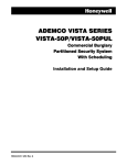
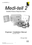
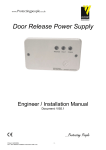
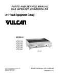
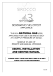
PowerMax+
Q u ick Fit K it E as y St a r t G u id e
STOP!
a
ll
P
re
En
r ol
le d
, P re
ady
- P ro g r a m m e d , R e
t
n
oI
st
Make a cup of tea, and spend the next
five minutes reading this information”.
Introduction
Welcome to PowerMax+, the wireless Home Security solution.
This guide provides some step by step information that will help
you get the system up and running.
Before you begin you should know that this kit is supplied with
the transmitters pre-enrolled and pre-programmed with the
most common settings. Additionally, each transmitter is labelled
with its zone or fob number on the rear plastic. Following this
guide will help you make basic configuration changes, for more
detailed information please refer to the full programming guide
included within the kit.
Finally….we have included a trouble shooting section to this
guide. BEFORE you ring the support line have a look through as
most common problems are listed here.
Whilst in any of the menus (user or installer) the following keys
will help you navigate the systems:– returns you to the start of the main menu.
– takes you back to the previous menu
– scrolls forward in the menu
– scrolls back in the menu
2) Choose a location to mount your control panel,
making sure it is at least 1m from any large metallic objects e.g.
Radiators, or RF equipment e.g. WiFi transmitters. Additionally
ensure there is access to a mains power supply and telephone
line if required.
Remove the bracket from the main control panel by undoing the
screw located at the bottom of the panel. Mark and fix as required
using three fixing points. Once done install the transformer,
remove the Euro plug and connect to the mains point via a 3pin
plug (not supplied) or for EN-50131 systems an unswitched fuse
spur (not supplied)
LL This is a professional product and is not suitable for DIY
installation
1
Keypad cover
(closed)
2
Control keys
3
Display
4
1) To Access the installer mode via the user menu. Press
until the display shows “User settings”, then press
and
enter the user code. Once in the user menu press
twice until
the display shows installer mode, then press
followed by
the installer code.
LL Default codes are :- User 1111 / Installer 9999.
Luminous
indicators
5
Microphone
6
Built-in siren
7
Battery
compartmemt
cover (closed)
8
Bracket screw
3
4
6
2
1
5
7
8
3) (Optional) Connect the Powermax to the telephone
line via terminals 2 & 5 on the BT socket, and the “Line” terminals
on Powermax. Alternatively, if you have a standard plug-in phone
lead remove the clear plastic (RJ11) plug and use the centre two
cores of the cable to connect to the line terminals (there is no
difference which way around these are connected).
LL If Broadband (ADSL) is enabled on the premises phone
line then you will need to fit a filter. Available from most
wholesalers.
LL Wireless PIR’s have a two minute sleep timer to save
battery life – On initial power up the unit will go through a
self test (LED flashing) then enter a walk test mode. If the
PIR has gone into sleep mode make each room vacant for
two minutes or open and close the lid before carrying out
the walk test.
MCT-320 Door Contact has a built in reed switch, for use with the
magnet supplied.
MCT-320
4) Power-up the PowerMax by connecting the battery first,
which fits in to the compartment on the main panel, then connect
the lead from the transformer to the 9VAC terminals.
LL The backup battery may take an hour to reach full capacity,
during this period the panel will report “CPU Low Battery”.
LL Depending the status of the panel and accessories the
display will show [READY – MEMORY] or [NOT READY –
MEMORY]. At any time you can press the status button on
to find out the faults/
the keyfob, or repeatedly press
memory conditions that are outstanding.
To install the main transmitter to the door or window frame,
ensuring that the curved edge is facing the opening section. The
magnet should be installed on the opening section no more than
5mm from the transmitter.
LL If the gap between the MCT-320 and magnet is to great use
the 7mm plastic spacer, provided within the kit, to increase
the height of the magnet.
•
•
Zone 1 - Front Door Contact. ‘Delay 1’ to start the Entry timer
Zone 2 - Hall PIR. ‘Perimeter Follow’ to allow user to walk
through during entry time to disarm
MCS-730 Wireless Siren is installed using the four fixing screws
provided. Note the fifth
screw should be fitted for
the back tamper (EN50131
MCS-730
Grade 2 installations) using
the fixing point in the centre
below the peizo siren. The
MCS-730 can be fitted with
a second battery for extended life and also has a comfort LED
which can be enabled/disabled via the jumper link in the battery
compartment. See MCS-730 manual for more information.
•
Zone 3 - Living Room PIR ‘Perimeter’ which will trigger the
alarm once armed
LL Important – The panel selector link inside the MCS battery
compartment must be in the PM+ position.
•
Zone 4 - Upstairs PIR ‘Interior’ which will only trigger when
armed in the Away mode
LL Note up to two MCS sirens can be fitted to the PowerMax.
5) Before you Install the Accessories we recommend that you
carry out a diagnostic check which is in section 7 of this guide.
Each device is labelled with its zone number. Make sure you note
this before installing.
Additionally each sensor supplied in this kit is pre- programmed
for the following:
PIR motion sensors should be sited to ensure that they do not
face into direct sunlight, windows, strong sources of heat and cold
(i.e. heaters, radiators, cold drafts or ventilators). They should also
be mounted at the correct
height (between 1.8 –
NEXT/
2.4m) in a position, for
K-985 MCW PET sensors, away from
stairs and that does not
allow animals to move
within 1m of the device.
To install, remove the cover, unclip the PCB, drill and fit in to
position being careful not to over tighten the screw and distort
the backplate. Then refit the PCB in to the back plate ensuring the
back tamper switch sits on to the metal spring.
Enrol additional devices by firstly removing from their packaging
and opening the cases near the Powermax. Then, whilst in
installer mode (see section 1 Accessing the Installer mode) press
until ‘Enrolling’ is shown, press
then:For PIR Movement sensors, Door Contact, Glassbreaks, hand held
panic buttons etc :-
•
Press
•
until you get to the next available zone (as default
Press
this will be zone 5) which will be indicated by having no black
marker on the right of the screen.
•
•
Press
until [Enrol Sensors] is show on the screen. Press
. At [Set Sensitivity] press
, then
again.
. ‘Transmit now’ will be on screen.
Add the battery supplied to the sensor you wish to enrol to
this zone.
Q u ick Fit K it E as y St a r t G u id e
•
Trigger a tamper on the sensor, trigger the input (for universal
or aux input on door contacts) or press button (for hand held
devices) to initiate a transmission.
•
Remove battery from transmitter, press
enrol an additional device.
, then
to
LL If a sensor has already been enrolled in another zone a long
error tone will be heard and the sensor will not be accepted
again.
LL PIR’s have back tampers which require both the front and
back tamper switch to be pressed simultaneously during
enrolling.
6) Defining the Zone Types will allow you to program what
happens when alarm sensors are triggered in the armed Away &
Home modes, whilst also being able to allocate a zone name and
chime setting. This section is only used for the Movement Sensor
and Door Contact.
You should be in the installer mode, press next until [Zone
, and enter the zone number
Definitions] is shown. Press
you need to program followed by
again.
and the existing setting will
At the screen Zone Type press
be shown, press
to scroll to the next option then press
and
again once you find the zone type required.
•
Interior—This zone will be turned off during the Home set
(ideal for Landing and bedroom detectors).
•
Interior Follower—This zone will allow access in the delay
mode (without triggering the alarm), and will also be turned
off during the Home set mode (Ideal for Hall sensors that
need to be off during the night).
•
Perimeter—This zone will trigger during the Away and Home
mode (ideal for Living rooms, Kitchens etc).
•
Perimeter Follower—Same as above but allows access through
the detector during the delay mode (ideal for Hallways).
•
Delay 1 & 2—These zones will start an entry timer when
activated during the Away or Home mode (ideal for the
front and back door which are being used as entry and exit
points).
LL Note: There are many more zone types. Please refer to the
installation manual for more information.
The next screen allows you to pick the [Zone Name]. As previously,
to enter the menu then press
to scroll through
press
the library until you find the name required then press
and
again to confirm.
to enter the chime option and select whether
Finally, press
you would like this to be Off, Melody or Zone name type.
7) The diagnostic testing feature is a useful tool for
determining the signal strength from the sensors deployed on
site. This should be carried out before and after you have installed
the system.
Whilst in installer mode main menu :-
•
Press
•
again (to test sensors) and ‘Diag. Testing’ will be
Press
on screen.
•
Now walk around the premises and trigger the sensors (see
note below).
•
key to cycle through the zone
Once completed use the
and check that all signals are ether ‘Good’ or ‘Strong’. If any
sensors show ‘poor’ re-site to a better position.
until the screen shows ‘Diagnostics’, then press
.
If a wireless siren is on the system then you can perform a remote
diagnostic check by selecting [WL Siren Test] in the Diagnostic
twice.
menu and pressing
LL If you find a sensor is out of range consider using a MCX-600
repeater. When powered via 12VDC this will boost signals
received from transmitters.
8) PowerMax has an onboard voice dialler which optionally,
can be used to contact your customer in the event of an alarm
activation or alert.
•
•
•
•
•
•
To enable, whilst in installer mode main menu :until the screen shows [Define Coms], then press
Press
until [20.Report>PRVT] is shown, then press
.
.
until [All (-op/cl)] is shown.
We recommend you press
This reports all alarm and tamper events to the user but not
when the system is armed or disarmed (for information on
the other options consult the programming guide).
Press
twice.
Phone numbers can be set in the installer mode (Define Coms
- option 17) or via the user settings
The House Identification is a recorded message played when
Powermax calls the user to notify them of an alarm.
To record this message ensure you are still in the installer mode:-
•
Press next until ‘Define Voice’ then press
will display ‘House Identity’.
•
To record the message press and hold the [2] button then
say the house ID e.g. “Mr & Mrs Smith, Blacksmith Cottage,
Truro.”.
•
Press [5] to listen to the message you recorded.
and the screen
Q u ick Fit K it E as y St a r t G u id e
9) Trouble Shooting
Q – Display - The system display shows [NOT READY] or [NOT
READY - TROUBLE]
then
, whilst in the menu will allow you to access the
programming option. Remember if you are changing a setting you
need to press the
key twice.
A – There is a fault outstanding, press the status button on any
keyfob or press the
button repeatedly and listen to each
message. Any “…Alarm” messages i.e. “Hall Tamper Alarm” can
be ignored however, zone and tamper open messages need to
be addressed i.e. “Hall Tamper OPEN”.
Q - Tamper - I have fitted a sensor with cover close but the system
is saying the tamper is OPEN, what is wrong ?
A - Typically this can happen on PIR sensors when the back plate is
not fitted well or the PCB board is incorrectly positioned. Remove
the PCB and check that the back tamper clicks when you refit it,
then replace the cover again listening for the tamper to click.
Q – Siren - The internal siren will sound on the control panel but
will not sound the external siren
A - This is due to the abort time found in the Installer mode‘Define Panel’-menu 5. If this is set to above 0 seconds it will
delay the external siren and telephone communications.
1
Away
2
2
Home
3
3
Disarm
4
4
Aux
1
+2
Panic (if enabled)
3
1
2
4
Q – Display - How do I clear the [READY - MEMORY] message?
A – Press the status button on the Keyfob or press
repeatedly
to review the memory condition. Start the ARMING process then
disarm the system. The memory prompt should be cleared.
1
User operation is via the keypad or keyfob (supplied).
When receiving a phone call from the Powermax System the
user will hear the House ID message followed by the type of
activation. The call must be acknowledged to prevent the system
contacting other Key-holders. To acknowledge press the “2”
button on the telephone keypad or “6” if you would like to listen
and talk through the PowerMax. Refer to your user guide for
more options.
You can also control the PowerMax remotely by ringing in. To do
this call the PowerMax / House phone number, let it ring twice
then hang up. Wait 20 seconds, then call again. You will hear a
modem type tone, then :-
Q – Communication - I have entered the private phone numbers
but the panel does not dial when the system is triggered.
Press ‘*’, then your user code, followed by ‘#’
A – You need to also enable option 20 in the define Coms menu.
See section 8 for more details.
•
•
•
•
Q – Panic – I am pressing the keyfob or panel panic buttons but
nothing happens.
A – You need to enable this facility to operate. In installer mode
press
until you see [Define Panel] then press
. Press
next until [12: Panic Alarm] then press
then press
to select the type (Silent or Audible) pressing
,
to
confirm.
Q – Diagnostics – When I test the devices the diagnostic screen
says certain devices are [NOT OK]
A – Each time you enter the Diagnostic menu the previous
reading are cleared and system needs to see a new signal from
the device. Simply repeat the test but make sure the device is
triggered (tamper or alarm)
You are now logged in and can use commands like:*, 1, # to Disarm the system
*, 3, # to Arm the system
*, 9, # to investigate the system status
*, 99,# to log off
LL For more options and instructions on how to ring in to the
system consult the User guide.
NEED HELP? Trade customer only call Visonic Product Support on
0870 7300830 or email [email protected]. End
users should contact their place of purchase.
Other products in the Visonic range:MCT-220 – Single push button
Deal for panic or emergency
applications
MCT-550 Flood Sensor
11) User Setting and Operation. Within the user settings
Detects early signs of
flooding within the home
MKP-150
Two way keypad
MCM-140
Single way keypad
you can add/delete keyfobs, set time and date, program phone
numbers etc. To select any of these options enter the user menu by
pressing
until [User Settings] is shown, then
. Pressing
MCT-442 CO Sensor
With inbuilt sounder, a
must for every home
MCT-124 – Double push
PowerMax and Next are registered trademarks of Visonic Ltd. Other names
are the property of their owners. Visonic reserves the right to change information or
specifications without notice. D-302607 (Rev.00)
MCT-425 Optical Smoke Detector
Tower-20 MCW
LPCP approved
Wireless External detector
Handheld panic button