1
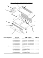
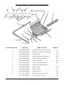
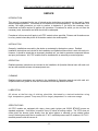
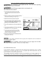
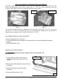
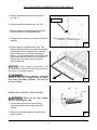
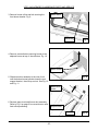
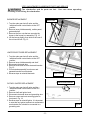
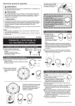
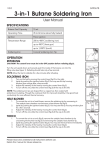
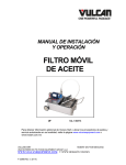
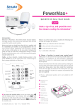
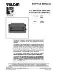
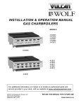
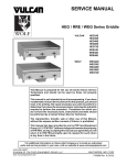
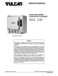
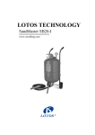
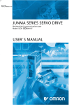
PARTS AND SERVICE MANUAL
GAS INFRARED CHARBROILER
MODELS
VTEC14
VTEC25
VTEC36
VTEC48
VTEC60
VTEC48
©ITW Food Equipment Group, LLC
3600 North Point Blvd.
Baltimore, MD 21222
RETAIN THIS MANUAL FOR FUTURE USE
FORM F38333 (11-11)
VTEC GAS INFRARED CHARBROILER PARTS AND SERVICE
17
16
1
15
14
2
13
12
3
4
5
6
11
8
10
ILLUSTRATION NO.
1………….
2………….
7
9
PART NO.
NAME OF PART
AMOUNT
00-944240-0014A….
VTEC14 inner shield assembly..
………..1
00-944240-0025A….
VTEC25 inner shield assembly..
………..1
00-944240-0036A….
VTEC36 inner shield assembly..
………..1
00-944240-0048A….
VTEC48 inner shield assembly..
………..1
00-944240-0060A….
VTEC60 inner shield assembly..
………..1
00-944236-00014….
VTEC14 back panel………………
………..1
00-944236-00025….
VTEC25 back panel………………
………..1
00-944236-00036….
VTEC36 back panel………………
………..1
00-944236-00048….
VTEC48 back panel………………
………..1
00-944236-00060….
VTEC60 back panel………………
………..1
-2-
VTEC GAS INFRARED CHARBROILER PARTS AND SERVICE
ILLUSTRATION NO.
PART NO.
NAME OF PART
AMOUNT
00-944241-00014…..
VTEC14 burner support bracket.
………..2
00-944241-00025…..
VTEC25 burner support bracket.
………..2
00-944241-00036…..
VTEC36 burner support bracket.
………..2
00-944241-00048…..
VTEC48 burner support bracket.
………..2
00-944241-00060…..
VTEC60 burner support bracket.
………..2
4………….
00-944253-00000…..
Crumb tray bracket deflector…..
………AR
5………….
00-944252-00000…..
Crumb tray bracket base….…….
………AR
6………….
00-944238-R000A….
Right side panel assembly………
………..1
7………….
00-719260-00000…..
Leg…………………………………..
………..4
8………….
00-944247-0014A….
VTEC14 crumb tray………………
………..1
00-944247-0025A….
VTEC25 crumb tray………………
………..1
00-944247-0036A….
VTEC36 crumb tray………………
………..1
00-944247-0024A….
VTEC48 crumb tray………………
………..2
00-944247-0030A….
VTEC60 crumb tray………………
………..2
9………….
00-944254-00000…..
Igniter knob………………………..
………AR
10………….
00-944233-0014A….
VTEC14 shelf………………………
………..1
00-944233-0025A….
VTEC25 shelf………………………
………..1
00-944233-0036A….
VTEC36 shelf………………………
………..1
00-944233-0048A….
VTEC48 shelf………………………
………..1
00-944233-0060A….
VTEC60 shelf………………………
………..1
11………….
00-413157-00001…..
Knob – chrome plated……………
………AR
12………….
00-944237-00014…..
VTEC14 front panel………………
………..1
00-944237-00025…..
VTEC25 front panel………………
………..1
00-944237-00036…..
VTEC36 front panel………………
………..1
00-944237-00048…..
VTEC48 front panel………………
………..1
00-944237-00060…..
VTEC60 front panel………………
………..1
13………….
00-944251-00000…..
Crumb tray bracket………………
………..1
14………….
00-944238-L000A….
Left side panel assembly……….
………..1
15………….
00-944244-00000…..
Emitter panel………………………
………AR
16………….
00-944245-0000A
Standard grate…………………….
………AR
00-944245-000FA
Fish grate…………………………..
………AR
00-944239-00000…..
Grate bracket………………………
………..2
3………….
17………….
-3-
VTEC GAS INFRARED CHARBROILER PARTS AND SERVICE
1
4
4
4
1
2
14
3
14
2
13
12
11
10
4
9
5
8
ILLUSTRATION NO.
7
6
PART NO.
NAME OF PART
AMOUNT
1………….
00-944246-0002S....
Outside burner-outside reflector.
………..2
2………….
00-944246-0000A....
Burner box (with orifice bracket)
………AR
3………….
00-944250-0000A….
VTEC burner……………………….
………AR
4………….
00-944246-00002….
Inside burner-inside reflector…..
………AR
5………….
00-944249-00001…..
Igniter electrode bracket………..
………AR
6………….
00-944249-00000…..
Igniter electrode…………………..
………AR
7………….
00-926523-00000…..
2.125” orifice extension…..……..
………AR
8………….
00-719363-00000…..
1/8 NPT countersink plug……….
………..1
9………….
00-944255-00000…..
Rotary igniter……..……………….
………AR
10………….
00-944243-00000…..
Burner valve……………………….
………AR
11………….
00-944246-00006…..
Orifice bracket…………………….
………AR
12………….
00-719951-00043
Natural gas burner orifice……….
………AR
00-719951-00054
LP gas burner orifice…………….
………AR
-4-
VTEC GAS INFRARED CHARBROILER PARTS AND SERVICE
ILLUSTRATION NO.
PART NO.
NAME OF PART
AMOUNT
00-944235-0014A....
VTEC14 Manifold…………………
………..1
00-944235-0025A....
VTEC25 Manifold…………………
………..1
00-944235-0036A....
VTEC36 Manifold…………………
………..1
00-944235-0048A....
VTEC48 Manifold…………………
………..1
00-944235-0060A....
VTEC60 Manifold…………………
………..1
14………….
00-944263-00000....
Burner reinforcement bracket….
………..2
Not Shown…....
00-944256-00010....
10” igniter wire…………………….
………AR
Not Shown…....
00-944256-00018....
18” igniter wire…………………….
………AR
Not Shown…....
00-408279-00026…..
Natural gas pressure regulator...
………..1
Not Shown…....
00-408279-00021…..
LP gas pressure regulator……...
………..1
Not Shown…....
00-944257-00000….
Stainless steel grate scraper…..
………..1
Not Shown…....
00-944276-00000….
Igniter grounding wire……………
………AR
13………….
RECOMMENDED SPARE PARTS
PART NO.
NAME OF PART
AMOUNT
00-408279-00026…..
Natural gas pressure regulator………………………….....
………..1
00-408279-00021…..
LP gas pressure regulator…….....................................
………..1
00-413157-00001…..
Knob – chrome plated…………………………….………..…
………..2
00-944254-00000…..
Igniter knob……………………………………………………..
………..1
00-944255-00000…..
Rotary igniter……..…………………………………………….
………..1
00-944256-00010....
10” igniter wire………………………………………………….
………..1
00-944256-00018....
18” igniter wire………………………………………………….
………..1
00-944249-00000…..
Igniter electrode………………………………………………..
………..2
00-944244-00000…..
Emitter panel……………………………………………………
………..2
00-926523-00000…..
2.125” orifice extension…..……………………………...…..
………..2
00-944243-00000…..
Burner valve…………………………………………………….
………..2
00-719951-00043
Natural gas burner orifice…………………………………….
………..2
00-719951-00054
LP gas burner orifice………………………………………….
………..2
-5-
VTEC GAS INFRARED CHARBROILER PARTS AND SERVICE
SERVICE
INTRODUCTION
This manual is prepared for the use of trained service technicians and should only be used by those
who are properly qualified. This manual is not intended to be all encompassing. You should read, in its
entirety, the repair procedure you wish to perform to determine if you have the necessary tools,
instruments and skills required to perform the procedure. Procedures for which you do not have the
necessary tools, instruments and skills should not be attempted.
Procedures in this manual will apply to all VTEC models unless specified. Pictures and illustrations can
be of any model unless the picture or illustration needs to be model specific.
INSTALLATION
Generally, installations are made by the dealer or contracted by the dealer or owner. Detailed
installation instructions are included in the Installation and Operation Manual that is sent with each unit.
However, it should be noted that an improperly installed unit, can lead to premature component failures
and poor performance. All VTEC models must be installed with an externally mounted regulator.
OPERATION
Detailed operation instructions are included in the Installation & Operation Manual sent with each unit
and are also available at www.vulcanequipment.com .
CLEANING
Detailed cleaning procedures are included in the Installation & Operation manual sent with each unit.
All places where oil, grease or food can accumulate must be kept clean at all times.
LUBRICATION
All valves, at the first sign of sticking, should be lubricated by a trained technician using
high temperature grease. Frequency will be largely dependent on customer usage.
SPECIFICATIONS
All VTEC models are equipped with rotary, piezo spark igniters and 22,000 BTU/HR burners as
standard equipment. One burner is used for every 12 inches of broiling surface. The VTEC does not
utilize pilots; the burners ignite directly from the peizo igniters or manually via an outside ignition
source. Natural gas models are to operate at 4.0" W.C. manifold pressure and LP models at 10.0" W.C.
manifold pressure with all burners on.
-6-
VTEC GAS INFRARED CHARBROILER PARTS AND SERVICE
The charbroiler and its parts are hot.
cleaning or servicing the charbroiler.
Use care when operating,
Shut off the gas supply before servicing the unit.
GAS PRESSURE MEASUREMENT
1. Turn the main gas shut-off valve and the
individual burner control knobs to the OFF
position.
2. Remove crumb tray. Remove pressure tap plug
underneath manifold pipe at right. Fig. 1.
3. Attach manometer at pressure tap point.
4. Turn main gas shut-off ON ,Ignite all burners
and leave on MAX setting while checking gas
pressure. See I&O Manual F-38330.
5. Turn all the equipment on the same supply line
on.
6. Gas pressure should be 4” W.C for natural gas
units and 10” W.C. for LP gas units.
Pressure tap
Fig. 1
7. Turn the main gas shut-off valve and the
individual burner control knobs to the OFF
position (clockwise until stops).
8. Disconnect manometer and reinstall pressure
tap plug and crumb tray.
All gas supply connections and any pipe joint compound must be resistant to
the action of propane gases.
Prior to lighting, check all joints in the gas supply line for leaks.
Use soap and water solution. Do not use an open flame.
GAS PRESSURE REGULATOR
A gas pressure regulator is supplied with the charbroiler and should be set at 4” Water
Column (W.C.) for natural gas, and 10” W.C. for propane gas. Minor adjustments may be
required based on site specific gas pressure.
The regulator should be installed as close to the charbroiler on the gas supply line as
possible. Make sure that the arrow on the underside of the regulator is oriented in the
-7-
VTEC GAS INFRARED CHARBROILER PARTS AND SERVICE
direction of gas flow to the broiler (Fig. 3) and the regulator is positioned with the vent
limiter and adjustment screw cover upright (Fig. 4). The vent limiter should be kept free
of grease and debris to prevent clogging and poor performance.
Vent limiter
Fig. 3
Adjustment cover
Fig. 4
The minimum supply pressure (upstream of the regulator) should be 7-9” W.C. for natural
gas and 11-12” W.C. for propane gas. At no time should the charbroiler be connected to
supply pressure greater than ½ psig (3.45 kPa) or 14” W.C.
GAS PRESSURE REGULATOR ADJUSTMENT
1. Remove adjustment cover. See Fig. 4.
2. Turn the adjustment screw clockwise to increase pressure and counterclockwise to decrease
pressure.
3. Reinstall adjustment cover.
BURNER VALVE REPLACEMENT
Shut off the gas supply before servicing the unit.
Unthread orifices
1. Turn the main gas shut-off valve and the
individual burner control knobs to the OFF
position.
2. Remove inner shield assembly, knobs, shelf and
front panel.
3. Disconnect all igniter wires at the igniter
electrodes.
4. Remove all burner orifices. Fig 5.
Fig. 5
-8-
VTEC GAS INFRARED CHARBROILER PARTS AND SERVICE
5. Remove manifold retaining screw at back of
unit. Fig. 6.
Remove screw
6. Remove manifold assembly from unit. Fig 7.
7. Measure distance between manifold pipe and
valve to reference for reassembly later.
8. Unthread orifice extension and burner valve from
manifold.
Fig. 6
9. Reverse steps to reinstall burner valve. The
distance between the burner valve and manifold
should match previous dimensions so that the
burner valve outlet is centered in the burner
venturi. The gap between the orifice and the end
of the burner venturi should be no more than ¼”.
Refer to Fig. 8 for correct burner valve and
orifice positioning.
All gas supply connections and
any pipe joint compound must be resistant to
the action of propane gases.
Prior to lighting, check all
joints in the gas supply line for leaks.
Use soap and water solution. Do not use
an open flame.
Fig. 7
¼” max
BURNER BOX ASSEMBLY REPLACEMENT
Shut off the gas supply
before servicing the unit.
1. Turn the main gas shut-off valve and the
individual burner control knobs to the OFF
position.
2. Remove inner shield assembly, emitter panel,
grate and shelf.
Fig. 8
-9-
VTEC GAS INFRARED CHARBROILER PARTS AND SERVICE
3. Remove burner orifice and bolt securing the
front burner bracket. Fig. 9.
Remove orifice
Remove bolt
Fig. 9
4. Remove screws that are securing burner to the
adjacent burner at top of the reflectors. Fig. 10.
Remove screws
Fig. 10
5. Slide burner box assembly to the rear of unit
until the bottom burner bracket clears the rear
support bracket, then lift up and out. See Fig. 10
and Fig. 11.
Bottom burner
bracket
6. Reverse steps to reinstall burner box assembly.
Refer to Fig. 8 on page 9 for correct burner valve
And orifice positioning.
Support bracket
Bottom View
- 10 -
Fig. 11
VTEC GAS INFRARED CHARBROILER PARTS AND SERVICE
The charbroiler and its parts are hot.
cleaning or servicing the charbroiler.
BURNER REPLACEMENT
Use care when operating,
Remove nuts
1. Turn the main gas shut-off valve and the
individual burner control knobs to the OFF
position.
2. Remove inner shield assembly, emitter panel,
grate and shelf.
3. Remove the four nuts that are securing the
burner to the burner box assembly. Fig. 12.
4. Lift the burner slightly, then slide to the rear of
the unit and lift out. Fig. 12.
Fig. 12
IGNITER ELECTRODE REPLACEMENT
1. Turn the main gas shut-off valve and the
individual burner control knobs to the OFF
position.
2. Remove inner shield assembly and shelf
3. Disconnect electrode wire.
4. Remove screw and nut from electrode bracket.
Fig. 13.
5. Pull electrode assembly from burner and
separate bracket from electrode.
6. Reverse steps to reinstall electrode.
Remove screw
Fig. 13
Remove screws and nuts
ROTARY IGNITER REPLACEMENT
1. Turn the main gas shut-off valve and the
individual burner control knobs to the OFF
position.
2. Remove shelf and igniter knob.
3. Disconnect electrode wires and grounding wire.
4. Remove screws and nuts securing igniter to
front panel. Fig. 14
5. Reverse steps to reinstall igniter. It is important
to note that any igniter terminal not connected to
an electrode wire, should be connected to a
grounding wire.
- 11 -
Fig. 14
VTEC GAS INFRARED CHARBROILER PARTS AND SERVICE
TROUBLE SHOOTING
Uneven heating
A.
B.
C.
D.
E.
Burner valves improperly adjusted
Fluctuating gas pressure
Appliance is not level
Emitter panels are not properly seated or damaged
Emitter panels are excessively dirty
Too much top heat
A.
C.
D.
E.
Faulty hood ventilation
Overrated gas pressure
Unit is excessively dirty
Emitter panels are not properly seated or damaged
Uneven heat side to side
A.
B.
C.
D.
E.
Burner valves improperly adjusted
Appliance is not level side to side
Crumb tray is not pushed all the way in
Emitter panels are not properly seated or damaged
Emitter panels are excessively dirty
Uneven heat front to back
A.
B.
C.
D.
E.
F.
Appliance is not level front to back
Faulty hood ventilation
Crumb tray is not pushed all the way in
Emitter panels are not properly seated or damaged
Emitter panels are excessively dirty
Designed air flow pattern obstructed
Burner not lighting
A. Check that igniter electrode is sparking when igniter
knob is turned clockwise
B. Check for damaged, loose or dirty igniter wires, igniter
and electrode
C. Check that at igniter terminal connections are connected
to an electrode wire or grounding wire. Should be no
empty terminals.
D. Burner valve not on MAX setting
E. Gas pressure too low
F. Inside burner box or burner venturi excessively dirty
Burner flames too low
A.
B.
C.
D.
Burner flames to high
A. Emitter panels are not properly seated or damaged
B. Gas pressure too high
Fluctuating gas pressure
A. Checked for clogged vent on regulator
Flames in burner venturi
A.
B.
C.
D.
Burner valves improperly adjusted
Gas pressure too low
Inside burner box or burner venturi excessively dirty
Clogged burner orifice
Appliance is not level
Gas pressure not set properly
Waiting too long before igniting burner
Not following lighting instructions - See I&O Manual
F-38330.
- 12 -
VTEC GAS INFRARED CHARBROILER PARTS AND SERVICE
NOTES
- 13 -
VTEC GAS INFRARED CHARBROILER PARTS AND SERVICE
- 14 -