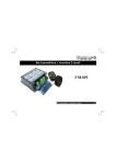
1
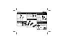
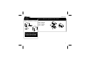
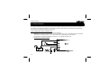
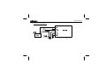
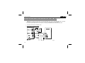
CAR BURGLAR ALARM K3504 e Low cost reliabl ILLUSTRATED ASSEMBLY MANUAL car alarm. H3504IP - 1 Features & Specifications The alarm detects sudden voltage drops of the battery when the interior, trunk, or hood lights are switched on. To ensure correct operation, a number of control indications have been included, such as : flashing LED to indicate that the alarm is in standby mode after a set time (after you have left the car). Pre-alarm (built-in buzzer) to indicate that the alarm is activated, so that you will not forget to switch it off. The alarm is easy to switch on and off, either automatically or by means of the ignition switch or a remote control unit, such as the K8059 / K8057 or VM109. Specifications: detects voltage drops of the battery entry delay time: 2 to 30 seconds with buzzer indication exit delay time: 2 to 180 seconds with LED indication alarm period: 60 seconds with automatic reset power supply: 12V standby current: 25mA relay output: 5A PCB dimensions: 62 x 100mm (2.4" x 3.9") recommended housing: WCAH2853 2 Assembly hints 1. Assembly (Skipping this can lead to troubles ! ) Ok, so we have your attention. These hints will help you to make this project successful. Read them carefully. 1.1 Make sure you have the right tools: A good quality soldering iron (25-40W) with a small tip. Wipe it often on a wet sponge or cloth, to keep it clean; then apply solder to the tip, to give it a wet look. This is called ‘thinning’ and will protect the tip, and enables you to make good connections. When solder rolls off the tip, it needs cleaning. Thin raisin-core solder. Do not use any flux or grease. A diagonal cutter to trim excess wires. To avoid injury when cutting excess leads, hold the lead so they cannot fly towards the eyes. Needle nose pliers, for bending leads, or to hold components in place. Small blade and Phillips screwdrivers. A basic range is fine. 0.0 00 For some projects, a basic multi-meter is required, or might be handy 1.2 Assembly Hints : Make sure the skill level matches your experience, to avoid disappointments. Follow the instructions carefully. Read and understand the entire step before you perform each operation. Perform the assembly in the correct order as stated in this manual Position all parts on the PCB (Printed Circuit Board) as shown on the drawings. Values on the circuit diagram are subject to changes. Values in this assembly guide are correct* Use the check-boxes to mark your progress. Please read the included information on safety and customer service * Typographical inaccuracies excluded. Always look for possible last minute manual updates, indicated as ‘NOTE’ on a separate leaflet. 3 Assembly hints 1.3 Soldering Hints : 1- Mount the component against the PCB surface and carefully solder the leads 2- Make sure the solder joints are cone-shaped and shiny 3- Trim excess leads as close as possible to the solder joint REMOVE THEM FROM THE TAPE ONE AT A TIME ! DO NOT BLINDLY FOLLOW THE ORDER OF THE COMPONENTS ONTO THE TAPE. ALWAYS CHECK THEIR VALUE ON THE PARTS LIST! 4 Construction 1. Jumper wires 2. 1/4W resistors D1 D2 D3 D4 D5 D6 R... J J J JI JC Continuous alarm : JC OR Intermittent alarm : JI R1 R2 R3 R4 R5 R6 R7 R8 R9 R10 R11 R12 R13 R14 R15 : : : : : : : : : : : : : : : 1K 1K 10K 47K 47K 47K 47K 47K 47K 680 1M 1M 1M 220K 220K 3. Diodes. Watch the polarity ! (1 - 0 - 2 - B) (1 - 0 - 2 - B) (1 - 0 - 3 - B) (4 - 7 - 3 - B) (4 - 7 - 3 - B) (4 - 7 - 3 - B) (4 - 7 - 3 - B) (4 - 7 - 3 - B) (4 - 7 - 3 - B) (6 - 8 - 1 - B) (1 - 0 - 5 - B) (1 - 0 - 5 - B) (1 - 0 - 5 - B) (2 - 2 - 4 - B) (2 - 2 - 4 - B) : : : : : : 1N4148 1N4148 1N4148 1N4148 1N4148 1N4148 CATHODE D... D7 : 1N4007 4. IC sockets. Watch the position of the notch! IC1 IC2 IC3 IC4 : : : : 8p 14p 16p 8p 5 Construction 5. Capacitors c... 7. Transistors 9. Electrolytic capacitor. Watch the polarity ! T1 : BC547C T2 : BC547C C5 : 4µ7 C6 : 4µ7 C7 : 4µ7 C8 : 220µF C9 : 220µF C10 : 47µF C11 : 47µF C12 : 100µF C13 : 100µF T3 : BC557B C1 C2 C3 C4 : : : : 10nF 10nF 100nF 100nF (103) (103) (104) (104) 8. Screw connectors 6. Trim potentiometers C... 10. Buzzer. Watch the polarity ! RV... RV1 : 4M7 RV2 : 1M BUZ1 Attention: the longest connection has to be put in the hole marked +. J1 : 3 x 2p 6 Construction 11. Relay 12. IC's. Watch the position of the notch! RY1 : VR15M121C (1 contact) IC1 : UA741M IC2 : CD4093 IC3 : CD4098 IC4 : NE555 RY... Apply some extra solder to the wider PCB tracks, starting from the relay contacts towards contacts “NO” and “COM”. 7 Test & usage 13. Test & Usage Connect the LED between the points LD1 and the earth (-). Connect the + and - of the battery direct to the + and - connections of the circuit. Remark: switching the + and - connections by mistake will only cause IC1 to be destroyed, because the rest of the circuit is protected by D7. + - + - Fig. 1 Turn both trimming potentiometers to their minimum position (completely to the left). The LED should be flashing now. 8 Test & usage Connecting the point DIS to the + should extinguish the LED. Interrupting the connection should restore the flashing state after 2 seconds. This delay time, which is the step out delay time or in other words the delay time between the point of time the voltage disappears from the point DIS (coming from the ignition lock or from the remote control) and the rearming of the alarm, can be made longer with RV1. Remark: when the circuit is first powered on, the delay times may deviate. This is caused by the fact that the circuit first has to stabilize. Fig. 2 The alarm, when armed, can be activated e.g. by switching the courtesy light (however the alarm DOESN'T react upon SWITCHING OFF loads). Before the relay, which controls the alarm signal, gets activated, you will hear a buzzer tone for 2 seconds so that you have time enough to switch off the alarm. This "step in delay time" can be made longer with RV2. Remark: To use the alarm together with the infrared code lock, it is advisable to set the step in and out delay times to their minimum. Together with the alarm you could also control the central car-door locking (possibly with an additional relay depending on the type of car-door locking). 9 Final connection 14. Final Connection Take care that the under mentioned connections cannot be cut through from the outside. You can install a lamp under the bonnet which activates the alarm when the bonnet is opened. Install the LED by preference at a place where it is visible from the outside (use the supplied LED-holder if necessary). Connect the shortest connection of the LED to the earth (chassis) and its shortest connection to the point LD1 of the circuit. (A) Car burglar alarm used as stand-alone unit. Connect the klaxon or siren to the relay as shown in the figures. Attention: The common wire of the klaxon can be connected either to the + or the - of the alarm (check with a volt-meter). Connect the connecting terminals"+" and"-" of the alarm to the corresponding poles of the battery. For normal use, connect the point DIS of the circuit to a"+" wire AFTER the ignition lock. 1. Warning device connected to chassis MAX. 5A 10 Fig. 3 Final connection 2. Warning device connected to "+" MAX. 5A Fig. 4 11 Final connection (B) Car burglar alarm used in combination with our RF codelock (K8057 & K8059 - VM109). Connect the klaxon or siren to the relay as shown in the figures. Attention: The common wire of the klaxon can be connected either to the + or the - of the alarm (check with a volt-meter). Connect the connecting terminals"+" and"-" of the alarm to the corresponding poles of the battery. Connect the point COM of the code lock with the "+" and the point NO with the connection DIS of the alarm. The receiver must be set to "TOGGLE" mode. 1. Warning device connected to chassis Fig. 5 12 Final connection 2. Warning device connected to "+" Fig. 6 K8057 : 2 Channel RF codelock receiver K8059 : 2 Channel RF codelock transmitter VM109 : 2 Channel RF remote control set 13 PCB 15. PCB 14 Schematic diagram 16. Schematic diagram. 15 VELLEMAN NV Legen Heirweg 33, B-9890 GAVERE Belgium (Europe) Modifications and typographical errors reserved © Velleman nv. H3504IP’1 - 2014 (rev.1) 5 410329 403485