1
®
Using ProLink Software
with Micro Motion
Transmitters
®
Instruction Manual
November 1999
®
Using ProLink Software
with Micro Motion
Transmitters
®
Instruction Manual
For technical assistance, phone the Micro Motion Customer
Service Department:
• In the U.S.A., phone 1-800-522-6277, 24 hours
• Outside the U.S.A., phone 303-530-8400, 24 hours
• In Europe, phone +31 (0) 318 549 443
• In Asia, phone 65-770-8155
Copyright ©1992, 1999, Micro Motion, Inc. All rights reserved.
Micro Motion, ELITE, and ProLink are registered trademarks, and PHOENIX and
FASTMASS are service marks of Micro Motion, Inc., Boulder, Colorado. Rosemount,
HART and SMART FAMILY are registered trademarks of Rosemount, Inc., Eden
Prairie, Minnesota. Modbus is a registered trademark of Modicon, Inc., North
Andover, Massachusetts. Hastelloy is a registered trademark of Haynes International,
Inc., Kokomo Indiana. Inconel is a registered trademark of Inco Alloys International,
Inc., Huntington, West Virginia. Teflon and Mylar are registered trademarks of E.I.
DuPont de Nemours Co., Inc., Wilmington, Delaware. Tantalum is a registered
trademark of Thai Tantalum, Inc., Gurnee, Illinois. Minigrabber is a registered
trademark of ITT Corp., New York, New York.
Contents
1 Before You Begin
..............................
About the ProLink® program . . . . . . . . . . . . . . . . . . . .
Uses of the ProLink® program . . . . . . . . . . . . . . . . . . .
File location . . . . . . . . . . . . . . . . . . . . . . . . . . . . . . . . .
The ProLink® kit and system requirements . . . . . . . . .
Customer service. . . . . . . . . . . . . . . . . . . . . . . . . . . . .
1
2 Getting Started . . . . . . . . . . . . . . . . . . . . . . . . . . . . . . . . .
5
1.1
1.2
1.3
2.1
2.2
2.3
2.4
2.5
2.6
2.7
2.8
2.9
Overview . . . . . . . . . . . . . . . . . . . . . . . . . . . . . . . . . . .
Communication standards. . . . . . . . . . . . . . . . . . . . . .
Wiring to the transmitter . . . . . . . . . . . . . . . . . . . . . . .
Connecting to the PC and power source. . . . . . . . . . .
Installing the software . . . . . . . . . . . . . . . . . . . . . . . . .
Start-up . . . . . . . . . . . . . . . . . . . . . . . . . . . . . . . . . . . .
Connecting to the transmitter . . . . . . . . . . . . . . . . . . .
Windows® hour glass . . . . . . . . . . . . . . . . . . . . . . . . .
Switch to another transmitter. . . . . . . . . . . . . . . . . . . .
Communication options . . . . . . . . . . . . . . . . . . . . . . . .
Transmitter communication options. . . . . . . . . . . . . . .
Software communication options. . . . . . . . . . . . . . . . .
Exit. . . . . . . . . . . . . . . . . . . . . . . . . . . . . . . . . . . . . . . .
1
2
2
2
3
5
6
7
12
13
18
18
21
22
22
22
23
25
3 File Menu: Database . . . . . . . . . . . . . . . . . . . . . . . . . . . 27
3.1
3.2
3.3
3.4
3.5
3.6
3.7
3.8
3.9
Using ProLink ® Software with Micro Motion® Transmitters
Overview . . . . . . . . . . . . . . . . . . . . . . . . . . . . . . . . . . .
File selection . . . . . . . . . . . . . . . . . . . . . . . . . . . . . . . .
Directory list box . . . . . . . . . . . . . . . . . . . . . . . . . . . . .
Transmitter configuration files list box . . . . . . . . . . . . .
File name text box . . . . . . . . . . . . . . . . . . . . . . . . . . . .
Database command buttons . . . . . . . . . . . . . . . . . . . .
Offline, save, and upload commands . . . . . . . . . . . . .
Offline and save. . . . . . . . . . . . . . . . . . . . . . . . . . . . . .
Upload . . . . . . . . . . . . . . . . . . . . . . . . . . . . . . . . . . . . .
Load command . . . . . . . . . . . . . . . . . . . . . . . . . . . . . .
Send command . . . . . . . . . . . . . . . . . . . . . . . . . . . . . .
Remove command . . . . . . . . . . . . . . . . . . . . . . . . . . .
On-screen viewing of transmitter
configuration files . . . . . . . . . . . . . . . . . . . . . . . . . .
Exporting transmitter configuration files . . . . . . . . . . .
27
28
28
29
29
29
30
30
30
31
31
32
32
32
i
Contents continued
4 File Menu: Print . . . . . . . . . . . . . . . . . . . . . . . . . . . . . . . . . 33
4.1
4.2
4.3
4.4
4.5
4.6
4.7
Overview . . . . . . . . . . . . . . . . . . . . . . . . . . . . . . . . . . .
Print setup . . . . . . . . . . . . . . . . . . . . . . . . . . . . . . . . . .
Select, edit, or create a ticket definition file . . . . . . . . .
Destination . . . . . . . . . . . . . . . . . . . . . . . . . . . . . . . . . .
Transmitter connections. . . . . . . . . . . . . . . . . . . . . . . .
Fields on ticket . . . . . . . . . . . . . . . . . . . . . . . . . . . . . . .
Separator and book ends. . . . . . . . . . . . . . . . . . . . . . .
Print . . . . . . . . . . . . . . . . . . . . . . . . . . . . . . . . . . . . . . .
Interval print . . . . . . . . . . . . . . . . . . . . . . . . . . . . . . . . .
Update rate . . . . . . . . . . . . . . . . . . . . . . . . . . . . . . . . .
Print file . . . . . . . . . . . . . . . . . . . . . . . . . . . . . . . . . . . .
Exporting print ticket files to other
software applications . . . . . . . . . . . . . . . . . . . . . . . .
33
33
34
35
35
36
37
38
39
40
41
41
5 File Menu: Error and Change Log Files . . . . . . . 43
5.1
5.2
Error logging . . . . . . . . . . . . . . . . . . . . . . . . . . . . . . . .
Log file name . . . . . . . . . . . . . . . . . . . . . . . . . . . . . . . .
Error log options. . . . . . . . . . . . . . . . . . . . . . . . . . . . . .
Change logging . . . . . . . . . . . . . . . . . . . . . . . . . . . . . .
Log file name . . . . . . . . . . . . . . . . . . . . . . . . . . . . . . . .
Change log options . . . . . . . . . . . . . . . . . . . . . . . . . . .
43
43
44
44
45
46
6 View Menu: Variables . . . . . . . . . . . . . . . . . . . . . . . . . . 47
6.1
6.2
6.3
6.4
Overview . . . . . . . . . . . . . . . . . . . . . . . . . . . . . . . . . . .
Process variables window . . . . . . . . . . . . . . . . . . . . . .
Output levels window . . . . . . . . . . . . . . . . . . . . . . . . . .
Copying displayed values to other
software applications . . . . . . . . . . . . . . . . . . . . . . . .
7 View Menu: Status
7.1
7.2
7.3
7.4
ii
.............................
Overview . . . . . . . . . . . . . . . . . . . . . . . . . . . . . . . . . . .
Fault outputs . . . . . . . . . . . . . . . . . . . . . . . . . . . . . . . .
Critical indicators . . . . . . . . . . . . . . . . . . . . . . . . . . . . .
"Not Configured" . . . . . . . . . . . . . . . . . . . . . . . . . . . . .
Transmitter failure indicators . . . . . . . . . . . . . . . . . . . .
Sensor failure and overrange indicators . . . . . . . . . . .
"Analog Input Error" and "Pressure Input Failure" . . . .
"Data Loss Possible" . . . . . . . . . . . . . . . . . . . . . . . . . .
Operational indicators . . . . . . . . . . . . . . . . . . . . . . . . .
"Calibration Failure" . . . . . . . . . . . . . . . . . . . . . . . . . . .
"Slug Flow". . . . . . . . . . . . . . . . . . . . . . . . . . . . . . . . . .
Analog and frequency saturated indicators . . . . . . . . .
"Raw Flow Overflow" and "Raw Elec.
Zero Overflow". . . . . . . . . . . . . . . . . . . . . . . . . . . . .
47
47
49
50
53
53
56
56
57
57
57
62
62
62
62
63
64
66
Using ProLink® Software with Micro Motion® Transmitters
Contents continued
7.5
Informational indicators . . . . . . . . . . . . . . . . . . . . . . . .
"Transmitter Initializing" . . . . . . . . . . . . . . . . . . . . . . . .
"Calibration In Progress" . . . . . . . . . . . . . . . . . . . . . . .
Zero indicators. . . . . . . . . . . . . . . . . . . . . . . . . . . . . . .
Analog Fixed indicators . . . . . . . . . . . . . . . . . . . . . . . .
"Frequency Output Fixed" . . . . . . . . . . . . . . . . . . . . . .
"Burst Mode" . . . . . . . . . . . . . . . . . . . . . . . . . . . . . . . .
Event indicators . . . . . . . . . . . . . . . . . . . . . . . . . . . . . .
"Error Cleared" . . . . . . . . . . . . . . . . . . . . . . . . . . . . . .
"Power Reset" . . . . . . . . . . . . . . . . . . . . . . . . . . . . . . .
"Security Breach". . . . . . . . . . . . . . . . . . . . . . . . . . . . .
"Display Readback Error" . . . . . . . . . . . . . . . . . . . . . .
8 Configure Menu: Characterize
8.1
8.2
8.3
8.4
8.5
8.6
8.7
................
Overview . . . . . . . . . . . . . . . . . . . . . . . . . . . . . . . . . . .
Flow calibration factor . . . . . . . . . . . . . . . . . . . . . . . . .
Sensor and transmitter shipped together . . . . . . . . . .
Model RE-01 Remote Electronics Unit replaced
in the field . . . . . . . . . . . . . . . . . . . . . . . . . . . . . . . .
Sensor or transmitter replaced in the field. . . . . . . . . .
Field flow-calibration . . . . . . . . . . . . . . . . . . . . . . . . . .
Density factors for RFT9739 . . . . . . . . . . . . . . . . . . . .
Density characterization for RFT9739 . . . . . . . . . . . . .
Density factor for IFT9701/IFT9703 and
RFT9712/RFT9729 . . . . . . . . . . . . . . . . . . . . . . . . .
Density characterization for IFT9701/IFT9703 and
RFT9712/RFT9729 . . . . . . . . . . . . . . . . . . . . . . . . .
Slug flow limits. . . . . . . . . . . . . . . . . . . . . . . . . . . . . . .
Temperature factor for RFT9739. . . . . . . . . . . . . . . . .
Pressure compensation with RFT9739 . . . . . . . . . . . .
Real-time compensation . . . . . . . . . . . . . . . . . . . . . . .
Compensation for stable operating pressures. . . . . . .
66
67
67
67
69
69
69
70
70
70
70
70
71
71
73
73
73
76
76
78
79
80
81
81
82
86
86
87
9 Configure Menu: Transmitter Variables . . . . . . . 91
9.1
9.2
9.3
9.4
9.5
9.6
9.7
Using ProLink ® Software with Micro Motion® Transmitters
Overview . . . . . . . . . . . . . . . . . . . . . . . . . . . . . . . . . . .
Flow units . . . . . . . . . . . . . . . . . . . . . . . . . . . . . . . . . .
Special flow units. . . . . . . . . . . . . . . . . . . . . . . . . . . . .
Special units of mass for gases. . . . . . . . . . . . . . . . . .
Density units . . . . . . . . . . . . . . . . . . . . . . . . . . . . . . . .
API gravity . . . . . . . . . . . . . . . . . . . . . . . . . . . . . . . . . .
API standard volume . . . . . . . . . . . . . . . . . . . . . . . . . .
Temperature and pressure units . . . . . . . . . . . . . . . . .
Flow cutoffs . . . . . . . . . . . . . . . . . . . . . . . . . . . . . . . . .
Flow direction . . . . . . . . . . . . . . . . . . . . . . . . . . . . . . .
Internal damping . . . . . . . . . . . . . . . . . . . . . . . . . . . . .
91
93
96
98
100
100
101
102
102
104
105
iii
Contents continued
10 Configure Menu: Transmitter Outputs . . . . . . . 107
10.1
10.2
10.3
10.4
10.5
10.6
Overview . . . . . . . . . . . . . . . . . . . . . . . . . . . . . . . . .
RFT9739 outputs . . . . . . . . . . . . . . . . . . . . . . . . . . .
IFT9701/IFT9703 outputs . . . . . . . . . . . . . . . . . . . .
RFT9712/RFT9729 outputs . . . . . . . . . . . . . . . . . . .
Frequency/pulse output . . . . . . . . . . . . . . . . . . . . . .
Frequency/pulse output scaling . . . . . . . . . . . . . . . .
Maximum pulse width for RFT9739 . . . . . . . . . . . . .
K-factor . . . . . . . . . . . . . . . . . . . . . . . . . . . . . . . . . .
Milliamp outputs . . . . . . . . . . . . . . . . . . . . . . . . . . . .
Milliamp output variables . . . . . . . . . . . . . . . . . . . . .
Range limits . . . . . . . . . . . . . . . . . . . . . . . . . . . . . . .
Milliamp output flow cutoffs for RFT9739 and
RFT9712/RFT9729 . . . . . . . . . . . . . . . . . . . . . . .
Added damping on RFT9739 outputs . . . . . . . . . . .
Fault indicators for RFT9739 . . . . . . . . . . . . . . . . . .
Configuring fault indicators for a Version 2 or
earlier RFT9739. . . . . . . . . . . . . . . . . . . . . . . . . .
Slug duration for RFT9739. . . . . . . . . . . . . . . . . . . .
Control output from RFT9739 . . . . . . . . . . . . . . . . .
107
109
109
109
109
110
111
112
112
112
113
113
114
115
116
116
117
11 Configure Menu: Transmitter Information . . . 119
11.1
11.2
11.3
11.4
11.5
Overview . . . . . . . . . . . . . . . . . . . . . . . . . . . . . . . . .
Transmitter database . . . . . . . . . . . . . . . . . . . . . . . .
Pressure input for RFT9739. . . . . . . . . . . . . . . . . . .
Burst control for RFT9739 and
RFT9712/RFT9729 . . . . . . . . . . . . . . . . . . . . . . .
Sensor database for RFT9739 and
RFT9712/RFT9729 . . . . . . . . . . . . . . . . . . . . . . .
12 Configure Menu: Events
12.1
12.2
12.3
12.4
.....................
Overview . . . . . . . . . . . . . . . . . . . . . . . . . . . . . . . . .
Configuring event parameters . . . . . . . . . . . . . . . . .
Current levels for milliamp events . . . . . . . . . . . . . .
Reading event states . . . . . . . . . . . . . . . . . . . . . . . .
13 Configure Menu: Meter Factors
13.1
13.2
13.3
iv
.............
Overview . . . . . . . . . . . . . . . . . . . . . . . . . . . . . . . . .
Meter factors for mass, volume, and density . . . . . .
Entering meter factors . . . . . . . . . . . . . . . . . . . . . . .
119
121
122
124
125
127
127
127
130
130
131
131
131
132
Using ProLink® Software with Micro Motion® Transmitters
Contents continued
14 Calibrate Menu . . . . . . . . . . . . . . . . . . . . . . . . . . . . . . . . 133
14.1
14.2
14.3
14.4
14.5
14.6
Overview . . . . . . . . . . . . . . . . . . . . . . . . . . . . . . . . . .
Auto zero . . . . . . . . . . . . . . . . . . . . . . . . . . . . . . . . . .
Diagnosing zeroing failure . . . . . . . . . . . . . . . . . . . . .
Programming auto zero for RFT9739 . . . . . . . . . . . .
Convergence limit . . . . . . . . . . . . . . . . . . . . . . . . . . .
Zero time . . . . . . . . . . . . . . . . . . . . . . . . . . . . . . . . . .
Density calibration . . . . . . . . . . . . . . . . . . . . . . . . . . .
Density calibration for RFT9739 . . . . . . . . . . . . . . . .
Density calibration for IFT9701/IFT9703 . . . . . . . . . .
Density calibration for RFT9712/RFT9729 . . . . . . . .
Temperature calibration for RFT9739 . . . . . . . . . . . .
Milliamp output trim . . . . . . . . . . . . . . . . . . . . . . . . . .
Preparing for milliamp output trim . . . . . . . . . . . . . . .
Performing milliamp output trim. . . . . . . . . . . . . . . . .
133
133
136
136
136
137
138
139
144
147
148
151
151
152
15 Test Menu . . . . . . . . . . . . . . . . . . . . . . . . . . . . . . . . . . . . . 155
15.1
15.2
15.3
15.4
Overview . . . . . . . . . . . . . . . . . . . . . . . . . . . . . . . . . .
Milliamp output testing. . . . . . . . . . . . . . . . . . . . . . . .
Performing milliamp output test . . . . . . . . . . . . . . . . .
Frequency/pulse output testing . . . . . . . . . . . . . . . . .
Performing the frequency/pulse output test. . . . . . . .
Test point diagnostics for Version 3 RFT9739 . . . . .
16 Applications Menu
16.1
16.2
16.3
............................
Overview . . . . . . . . . . . . . . . . . . . . . . . . . . . . . . . . . .
Totalizer control . . . . . . . . . . . . . . . . . . . . . . . . . . . . .
Application builder . . . . . . . . . . . . . . . . . . . . . . . . . . .
155
156
156
157
158
158
161
161
161
163
17 Help Menu . . . . . . . . . . . . . . . . . . . . . . . . . . . . . . . . . . . . . 165
17.1
17.2
17.3
17.4
17.5
17.6
17.7
Using ProLink ® Software with Micro Motion® Transmitters
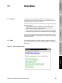
Overview . . . . . . . . . . . . . . . . . . . . . . . . . . . . . . . . . .
Index . . . . . . . . . . . . . . . . . . . . . . . . . . . . . . . . . . . . .
Keyboard . . . . . . . . . . . . . . . . . . . . . . . . . . . . . . . . . .
Using Help . . . . . . . . . . . . . . . . . . . . . . . . . . . . . . . . .
Context-sensitive Help. . . . . . . . . . . . . . . . . . . . . . . .
Getting around in Help. . . . . . . . . . . . . . . . . . . . . . . .
Contents . . . . . . . . . . . . . . . . . . . . . . . . . . . . . . . . . .
Search . . . . . . . . . . . . . . . . . . . . . . . . . . . . . . . . . . . .
Back. . . . . . . . . . . . . . . . . . . . . . . . . . . . . . . . . . . . . .
History . . . . . . . . . . . . . . . . . . . . . . . . . . . . . . . . . . . .
Browse. . . . . . . . . . . . . . . . . . . . . . . . . . . . . . . . . . . .
Jumping from one Help topic to another . . . . . . . . . .
Glossary of terms . . . . . . . . . . . . . . . . . . . . . . . . . . .
165
165
166
166
166
167
167
167
167
167
167
168
168
v
Contents continued
Appendixes
Appendix A How to Specify the ProLink® Product . . . . . . . . . .
Appendix B Uploading and Downloading Configuration Files
with a Model 268 . . . . . . . . . . . . . . . . . . . . . . . .
Appendix C Temperature Coefficients for Flow and Density . .
Appendix D ASCII Character Set . . . . . . . . . . . . . . . . . . . . . . .
Appendix E Transmitter Configuration Worksheets . . . . . . . . .
Appendix F Flowmeter Calibration Records . . . . . . . . . . . . . . .
169
171
177
181
183
189
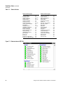
Figures
Figure 1-1
Figure 2-1
Figure 2-2
Figure 2-3
Figure 2-4
Figure 2-5
Figure 2-6
Figure 2-7
Figure 3-1
Figure 3-2
Figure 3-3
Figure 3-4
Figure 4-1
Figure 4-2
Figure 4-3
Figure 4-4
Figure 4-5
Figure 4-6
Figure 4-7
Figure 4-8
Figure 5-1
Figure 5-2
Figure 5-3
Figure 5-4
Figure 6-1
Figure 6-2
Figure 6-3
Figure 6-4
Figure 6-5
Figure 6-6
Figure 6-7
vi
ProLink® kit . . . . . . . . . . . . . . . . . . . . . . . . . . . . . .
PC Interface adaptor . . . . . . . . . . . . . . . . . . . . . . .
Bell 202 temporary connection to
field-mount transmitters. . . . . . . . . . . . . . . . . . .
Bell 202 temporary connection to
rack-mount transmitters . . . . . . . . . . . . . . . . . .
Bell 202 hard-wiring to transmitters or
multidrop networks . . . . . . . . . . . . . . . . . . . . . .
RS-485 hard-wiring to transmitters or
multidrop networks . . . . . . . . . . . . . . . . . . . . . .
Installing the PC Interface adaptor . . . . . . . . . . . .
Configure Communications dialog box . . . . . . . . .
Transmitter Database dialog box. . . . . . . . . . . . . .
Change Database Directory dialog box. . . . . . . . .
File Overwrite dialog box . . . . . . . . . . . . . . . . . . . .
Typical transmitter configuration file . . . . . . . . . . .
Print Setup/Ticket Builder dialog box. . . . . . . . . . .
Ticket File Name dialog box . . . . . . . . . . . . . . . . .
Add Transmitter Tag dialog box . . . . . . . . . . . . . .
Edit Field Tag Parameter dialog box . . . . . . . . . . .
Typical ticket printed using print command . . . . . .
Typical ticket printed using interval
print command . . . . . . . . . . . . . . . . . . . . . . . . .
Print - View - Application - Update Rate
dialog box . . . . . . . . . . . . . . . . . . . . . . . . . . . . .
Select File To Print dialog box. . . . . . . . . . . . . . . .
Typical error log file . . . . . . . . . . . . . . . . . . . . . . . .
Error Log dialog box . . . . . . . . . . . . . . . . . . . . . . .
Typical change log file . . . . . . . . . . . . . . . . . . . . . .
Change Log dialog box . . . . . . . . . . . . . . . . . . . . .
Process variables window
for RFT9739 . . . . . . . . . . . . . . . . . . . . . . . . . . .
Process variables window for
IFT9701/IFT9703 . . . . . . . . . . . . . . . . . . . . . . .
Process variables window for
RFT9712/RFT9729 . . . . . . . . . . . . . . . . . . . . . .
Output Levels window for RFT9739 . . . . . . . . . . .
Output Levels window for IFT9701
or IFT9703. . . . . . . . . . . . . . . . . . . . . . . . . . . . .
Output Levels window for RFT9712/9729 . . . . . . .
Copy or Link dialog box . . . . . . . . . . . . . . . . . . . . .
3
5
8
9
10
11
12
24
28
29
31
32
34
34
35
36
39
39
40
41
43
43
45
45
48
48
48
49
50
50
51
Using ProLink® Software with Micro Motion® Transmitters
Contents continued
Figure 7-1
Figure 7-2
Figure 7-3
Figure 7-4
Figure 8-1
Figure 8-2
Figure 9-1
Figure 9-2
Figure 9-3
Figure 9-4
Figure 9-5
Figure 9-6
Figure 10-1
Figure 10-2
Figure 10-3
Figure 11-1
Figure 11-2
Figure 11-3
Figure 12-1
Figure 13-1
Figure 14-1
Figure 14-2
Figure 14-3
Figure 14-4
Figure 14-5
Figure 14-6
Figure 14-7
Figure 14-8
Figure 14-9
Figure 14-10
Figure 14-11
Using ProLink ® Software with Micro Motion® Transmitters
Status window for RFT9739 . . . . . . . . . . . . . . . . .
Status window for IFT9701/IFT9703 . . . . . . . . . . .
Status window for RFT9712/RFT9729 . . . . . . . . .
Test Point Diagnostics dialog box . . . . . . . . . . . . .
Characterize Sensor dialog box
for RFT9739 . . . . . . . . . . . . . . . . . . . . . . . . . . .
Characterize Sensor dialog box for
IFT9701/IFT9703 or RFT9712/RFT9729 . . . . .
Configure Transmitter Variables dialog box
for RFT9739 . . . . . . . . . . . . . . . . . . . . . . . . . . .
Configure Transmitter Variables dialog box
for IFT9701/IFT9703. . . . . . . . . . . . . . . . . . . . .
Configure Transmitter Variables dialog box for
RFT9712/RFT9729. . . . . . . . . . . . . . . . . . . . . .
Configure Special Units dialog box
for RFT9739 . . . . . . . . . . . . . . . . . . . . . . . . . . .
Configure Special Units dialog box for
RFT9712/RFT9729. . . . . . . . . . . . . . . . . . . . . .
RFT9739 for Gas . . . . . . . . . . . . . . . . . . . . . . . . .
Configure Outputs dialog box
for RFT9739 . . . . . . . . . . . . . . . . . . . . . . . . . . .
Configure Outputs dialog box for
IFT9701/IFT9703 . . . . . . . . . . . . . . . . . . . . . . .
Configure Outputs dialog box for
RFT9712/RFT9729. . . . . . . . . . . . . . . . . . . . . .
Transmitter Information dialog box
for RFT9739 . . . . . . . . . . . . . . . . . . . . . . . . . . .
Transmitter Information dialog box for
IFT9701 or IFT9703 . . . . . . . . . . . . . . . . . . . . .
Transmitter Information dialog box for
RFT9712 or RFT9729. . . . . . . . . . . . . . . . . . . .
Configure Events dialog box . . . . . . . . . . . . . . . . .
Configure Meter Factors dialog box . . . . . . . . . . .
Flow Calibration dialog box for RFT9739 . . . . . . .
Flow Calibration dialog box for
IFT9701/IFT9703 . . . . . . . . . . . . . . . . . . . . . . .
Flow Calibration dialog box for
RFT9712/RFT9729. . . . . . . . . . . . . . . . . . . . . .
Density Point 1 Calibration dialog box
for RFT9739 . . . . . . . . . . . . . . . . . . . . . . . . . . .
Density Point 2 Calibration dialog box
for RFT9739 . . . . . . . . . . . . . . . . . . . . . . . . . . .
Density Point 3 Calibration dialog box
for RFT9739 . . . . . . . . . . . . . . . . . . . . . . . . . . .
Density Point 1 Calibration dialog box for
IFT9701/IFT9703 . . . . . . . . . . . . . . . . . . . . . . .
Density Point 2 Calibration dialog box
for IFT9701 . . . . . . . . . . . . . . . . . . . . . . . . . . . .
Density Point 1 Calibration dialog box for
RFT9712/RFT9729. . . . . . . . . . . . . . . . . . . . . .
Density Point 2 Calibration dialog box for
RFT9712/RFT9729. . . . . . . . . . . . . . . . . . . . . .
Temperature Offset Calibration dialog box . . . . . .
54
55
55
59
72
72
92
92
92
97
97
100
108
108
108
120
120
120
128
132
135
135
135
140
143
144
146
146
147
148
150
vii
Contents continued
Figure 14-12 Temperature Slope Calibration dialog box . . . . . . 150
Figure 14-13 Connecting a reference device to
a transmitter . . . . . . . . . . . . . . . . . . . . . . . . . . . 152
Figure 14-14 Milliamp output trim: setting output to 4 mA . . . . . 153
Figure 14-15 Milliamp output trim: enter measured
low output . . . . . . . . . . . . . . . . . . . . . . . . . . . . . 153
Figure 14-16 Milliamp output trim: enter measured
high output . . . . . . . . . . . . . . . . . . . . . . . . . . . . 154
Figure 15-1 Test Milliamp Outputs dialog box . . . . . . . . . . . . . 157
Figure 15-2 Test Frequency Outputs dialog box. . . . . . . . . . . . 158
Figure 15-3 Test points dialog box . . . . . . . . . . . . . . . . . . . . . . 159
Figure 16-1 Totalizer Control dialog box for RFT9739 and
RFT9712/RFT9729 . . . . . . . . . . . . . . . . . . . . . . 162
Figure 16-2 Totalizer Control dialog box for
IFT9701/IFT9703 . . . . . . . . . . . . . . . . . . . . . . . 162
Figure 17-1 ProLink Help main index . . . . . . . . . . . . . . . . . . . . 165
Figure 17-2 Typical ProLink Help display . . . . . . . . . . . . . . . . . 166
Tables
Table 1-1
Table 2-1
Table 2-2
Table 2-3
Table 3-1
Table 7-1
Table 7-2
Table 7-3
Table 7-4
Table 7-5
Table 7-6
Table 7-7
Table 7-8
Table 8-1
Table 8-2
Table 8-3
Table 8-4
viii
ProLink® compatibility . . . . . . . . . . . . . . . . . . . . . .
Wiring diagrams for PC interface
and transmitters . . . . . . . . . . . . . . . . . . . . . . . .
Troubleshooting the "cannot find" message . . . . .
Additional ProLink troubleshooting
information . . . . . . . . . . . . . . . . . . . . . . . . . . . .
Items not saved or restored with the
transmitter database . . . . . . . . . . . . . . . . . . . . .
Status indicators . . . . . . . . . . . . . . . . . . . . . . . . . .
Sensor and transmitter terminal designations . . . .
Troubleshooting excessive drive gain . . . . . . . . . .
Nominal resistance and voltage ranges for
flowmeter circuits . . . . . . . . . . . . . . . . . . . . . . .
Troubleshooting faulty sensor cable . . . . . . . . . . .
Troubleshooting overrange conditions . . . . . . . . .
Troubleshooting operational failures . . . . . . . . . . .
Troubleshooting informational failures. . . . . . . . . .
Temperature coefficients for flow . . . . . . . . . . . . .
Methods for determining RFT9739
density factors . . . . . . . . . . . . . . . . . . . . . . . . . .
Methods for determining IFT9701/IFT9703 or
RFT9712/9729 density factors . . . . . . . . . . . . .
Pressure correction factors . . . . . . . . . . . . . . . . . .
3
7
19
22
30
54
58
59
60
60
61
63
68
74
80
81
87
Using ProLink® Software with Micro Motion® Transmitters
Contents continued
Table 9-1
Table 9-2
Table 9-3
Table 9-4
Table 9-5
Table 9-6
Table 9-7
Table 9-8
Table 9-9
Table 9-10
Table 9-11
Table 10-1
Table 10-2
Table 11-1
Table 11-2
Table 11-3
Table 12-1
Table 14-1
Table 14-2
Table 14-3
Table 14-4
Table 14-5
Table 15-1
Table 15-2
Table 16-1
Using ProLink ® Software with Micro Motion® Transmitters
Mass flow measurement units for
process variables . . . . . . . . . . . . . . . . . . . . . .
Mass total and mass inventory measurement
units for process variables . . . . . . . . . . . . . . .
Viscosity measurement units for
process variables . . . . . . . . . . . . . . . . . . . . . .
Density measurement units for
process variables . . . . . . . . . . . . . . . . . . . . . .
Temperature measurement units for
process variables . . . . . . . . . . . . . . . . . . . . . .
Volume flow rate measurement units for process
variables (liquids only) . . . . . . . . . . . . . . . . . .
Volume total and volume inventory
measurement units for process variables . . . .
Differential pressure measurement units for
process variables . . . . . . . . . . . . . . . . . . . . . .
Effect of flow direction on outputs . . . . . . . . . . . .
Software versions and dates for
NAMUR compliance . . . . . . . . . . . . . . . . . . . .
Filter coefficients for internal damping on
process variables . . . . . . . . . . . . . . . . . . . . . .
RFT9739 Frequency/pulse variables
and output. . . . . . . . . . . . . . . . . . . . . . . . . . . .
Filter coefficients for added damping on
RFT9739 milliamp outputs . . . . . . . . . . . . . . .
Parameters that increment event registers . . . . .
HART commands for burst mode . . . . . . . . . . . .
Flange types, tube and liner
material options . . . . . . . . . . . . . . . . . . . . . . .
Event setpoint and process
variable comparison . . . . . . . . . . . . . . . . . . . .
Minimum flow rate for third-point
calibration . . . . . . . . . . . . . . . . . . . . . . . . . . . .
Density of air . . . . . . . . . . . . . . . . . . . . . . . . . . . .
Maximum flow rates for Micro Motion
sensors . . . . . . . . . . . . . . . . . . . . . . . . . . . . . .
Density of water . . . . . . . . . . . . . . . . . . . . . . . . .
Milliamp output terminals . . . . . . . . . . . . . . . . . .
Milliamp output terminals . . . . . . . . . . . . . . . . . .
Frequency/pulse output terminals . . . . . . . . . . . .
Totalizer Control for the RFT9739 . . . . . . . . . . .
94
94
94
95
95
95
96
96
104
105
106
110
114
122
125
125
128
139
141
142
143
151
156
157
163
ix
x
Using ProLink® Software with Micro Motion® Transmitters
Before You Begin
About the ProLink®
program
Getting Started
1.1
Before You Begin
1
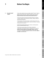
This manual explains how to use the Micro Motion® ProLink™ software
program under the Microsoft® Windows® graphical environment for
IBM-compatible personal computers. Before using this instruction
manual, the reader should be familiar with Microsoft Windows.
The ProLink program provides communication between a personal
computer and Micro Motion RFT9739, IFT9701, IFT9703, RFT9712,
and RFT9729 transmitters.
The ProLink program presents menus, windows, and dialog boxes
familiar to Microsoft Windows users.
File Menu: Print
The ProLink program enables off-line editing of transmitter
configurations, and enables transfer of configurations to or from the
ProLink transmitter database or data storage media, or from the
database to a Rosemount Model 268 SMART FAMILY® hand-held
communicator. The ProLink program cannot be used with a Model
275 HART® Communicator.
File Menu: Database
The Micro Motion PC Interface adaptor, included with the ProLink kit,
converts Bell 202 or RS-485 signals to and from the RS-232-C standard
used by personal computers.
File Menu: Log Files
1
View Menu: Variables
Using ProLink® Software with Micro Motion® Transmitters
Before You Begin continued
The ProLink® kit and system requirements
Uses of the ProLink®
program
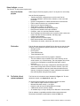
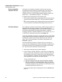
While using the ProLink program, press F1 at any time for on-line help.
Use the ProLink program to:
• Transfer transmitter configurations to and from the ProLink
transmitter database, the hard drive, diskettes, or the connected
transmitter
• Upload a configuration to a Model 268 hand-held communicator
• Poll for data from devices on a multidrop network
• Set up an error log and change log
• Send data to a printer or an ASCII file
• Configure measurement units and range limits
• Read process variables and output variables
• Configure, read, trim, and test transmitter outputs
• Store messages and information such as sensor serial number and
model, flow tube and liner materials, and flange type
• Calibrate the flowmeter
• Assign events to RFT9739 outputs
• Reset the transmitter internal totalizers
• Troubleshoot the sensor, transmitter, and cable connections
File location
ProLink files are saved to the default ProLink directory on the personal
computer, unless otherwise specified by the user. Such files include:
• Change log files
• Error log files
• Ticket definition files
• Ticket destination files
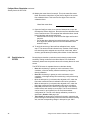
If a previous release of the ProLink program is installed:
• The new software may be installed in the same directory as the
earlier version, or in a new directory. The new program files will not
overwrite any configuration or default files that were created
previously.
• The new software will use any configuration and default files that
were created using earlier ProLink versions. However, if the new
software is installed in a directory other than the default ProLink
directory, it might be necessary to locate configuration and default
files manually when using the new program.
1.2
The ProLink® kit and
system requirements
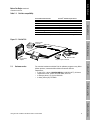
The ProLink® kit includes the items illustrated in Figure 1-1. To order
replacement parts, see Appendix A, page 169.
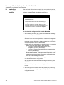
To use the ProLink program, the personal computer must have:
• Intel® 80386 or higher version microprocessor
• Microsoft Windows version 3.1 or higher
• Hard drive with at least 2.5 MB available for storage
• 4 MB random-access memory (RAM)
• An available 9-pin or 25-pin serial port for RS-232-C communication
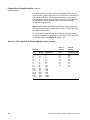
ProLink software compatibility with Micro Motion transmitters and
Rosemount hand-held communicators is listed in Table 1-1.
2
Using ProLink® Software with Micro Motion® Transmitters
Before You Begin
Before You Begin continued
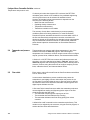
Customer service
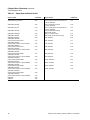
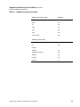
Table 1-1. ProLink® compatibility
Transmitter/communicator
ProLink® software requirement
Getting Started
RFT9739 Version 3.6
ProLink version 2.4
RFT9739 Version 3, 3.5
ProLink version 2.3
RFT9739 Version 2
ProLink version 2.1
RFT9739 earlier than version 2
Any ProLink version
IFT9701, IFT9703
ProLink version 2.2 or higher
RFT9712, RFT9729
Any ProLink version*
HART® Communicator Model 275
Not compatible with ProLink program
SMART FAMILY® Interface Model 268
Any ProLink version
*RFT9712 and RFT9729 require transmitter software version 5.0 or higher.
Figure 1-1. ProLink® kit
File Menu: Database
AC/DC power
converter
Bell 202 cable
PC Interface
adaptor
Customer service
25-pin to 9-pin converter
For technical assistance with the ProLink software program or any Micro
Motion product, contact the Micro Motion Customer Service
Department:
• In the U.S.A., phone 1-800-522-MASS (1-800-522-6277), 24 hours
• Outside the U.S.A., phone 303-530-8400, 24 hours
• In Europe, phone +31 (0) 318 549 443
• In Asia, phone (65) 770-8003
File Menu: Print
1.3
3.5-inch diskette
File Menu: Log Files
3
View Menu: Variables
Using ProLink® Software with Micro Motion® Transmitters
4
Using ProLink® Software with Micro Motion® Transmitters
Getting Started
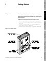
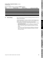
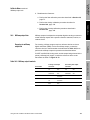
Overview
Depending on the transmitter model, communication with the flowmeter
uses the Bell 202 and/or RS-485 communication standards. The PC
Interface adaptor, shown in Figure 2-1, converts Bell 202 or RS-485
signals from the flowmeter to and from the RS-232-C standard used by
personal computers.
Getting Started
2.1
Before You Begin
2
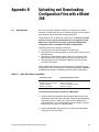
Installing the ProLink program requires the following four steps:
Figure 2-1. PC Interface adaptor
File Menu: Database
1. Choose a communication standard, as described in Section 2.2.
2. Connect the PC Interface adaptor to the transmitter, as described in
Section 2.3.
3. Install the PC Interface adaptor to the personal computer and a
power supply, as described in Section 2.4.
4. Install the ProLink software program, as described in Section 2.5.
File Menu: Print
File Menu: Log Files
5
View Menu: Variables
Using ProLink® Software with Micro Motion® Transmitters
Getting Started continued
Communication standards
2.2
Communication standards
Switches and jumpers on the transmitter determine the communication
standard used by the transmitter. Micro Motion configures each
transmitter's default communication settings at the factory.
Depending on the transmitter model, transmitters can communicate
using HART and/or Modbus ® protocol, using the Bell 202 or RS-485
standard. Communication configuration for the ProLink program and
transmitter must be the same.
Factory-default settings
The factory default settings for Version 3 RFT9739 transmitters are:
• HART protocol over the Bell 202 standard at 1200 baud, 1 stop bit,
odd parity
• Modbus protocol over the RS-485 standard at 9600 baud, 1 stop bit,
odd parity
The factory default settings for the IFT9701, IFT9703, RFT9712, and
RFT9729 are: HART protocol over the Bell 202 standard at 1200 baud, 1
stop bit, odd parity.
User configuration
Transmitter models RFT9739, RFT9712, and RFT9729 can be
reconfigured for user-defined communication settings using switches
and jumpers on the transmitter. To establish a user-defined
communication configuration, see the transmitter instruction manual.
HART® and Modbus® communication
The primary variable milliamp output on the RFT9739, and the 4-20 mA
output on the IFT9701, IFT9703, RFT9712, and RFT9729 can produce
HART-compatible signals for Bell 202 communication.
Micro Motion transmitters can function as part of a Bell 202 or RS-485
multidrop network.
• The RFT9739 can use the Bell 202 or RS-485 standard under HART
protocol, or the RS-485 standard under Modbus protocol.
• The IFT9701 and IFT9703 can use the Bell 202 standard under
HART protocol only.
• The RFT9712 and RFT9729 can use the Bell 202 or RS-485
standard under HART protocol only.
Up to 15 transmitters can participate with other devices in a Bell 202
multidrop network. Each transmitter must have a unique polling address
of 1 to 15, or a unique tag name.
Up to 32 transmitters can participate in an RS-485 multidrop network.
Each transmitter must have a unique tag name; up to 15 transmitters
may have unique polling addresses from 1 to 15. The IFT9701 and
IFT9703 cannot communicate in an RS-485 network.
6
Using ProLink® Software with Micro Motion® Transmitters
Wiring to the transmitter
2.3
Wiring to the transmitter
Wiring connections to RFT9739, IFT9701, IFT9703, RFT9712, and
RFT9729 transmitters are shown on the following pages. The configured
communication standard (Bell 202 or RS-485) determines how the
transmitter and PC Interface adaptor are wired together.
Getting Started
Table 2-1 lists the appropriate wiring diagrams for temporary
connections to transmitters using the Bell 202 standard, and for
hard-wiring to individual transmitters and multidrop networks using the
Bell 202 and RS-485 standards.
Table 2-1. Wiring diagrams for PC interface and transmitters
Communication standard
Type of Connection
Transmitters
Wiring diagram
Bell 202
Temporary connection to
field-mount transmitters1
Temporary connection to
rack-mount transmitters
Hard-wiring to individual
transmitters or multidrop
networks
RFT9739
RFT9712
RFT9739
RFT9729
RFT9739
IFT9701
IFT9703
RFT9712
RFT9729
RFT9739
RFT9712
RFT9729
Figure 2-2
Hard-wiring to individual
transmitters or multidrop
networks
Figure 2-3
Figure 2-4
File Menu: Database
RS-4852
Figure 2-5
1 There
2
Before You Begin
Getting Started continued
are no temporary field connections on the IFT9701 or IFT9703.
RS-485 not supported by the IFT9701 or IFT9703.
File Menu: Print
File Menu: Log Files
7
View Menu: Variables
Using ProLink® Software with Micro Motion® Transmitters
Getting Started continued
Wiring to the transmitter
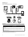
Figure 2-2. Bell 202 temporary connection to field-mount transmitters
R3
(Note 3)
R2
DCS or PLC
with internal
resisitor
(Note 2)
R4
(Note 4)
R1
(Note 1)
AC
Adaptor
Receive
Transmit
Power
Low Batt
485
202 Off 485
202
14 15 16 17 18 19 20
21 22 23 24 25 26 27
RFT9739
field-mount
19 18 17 16 15 14
26 25 24 23 22 21
A
B
P
S
Communicator hook-up loops
same as primary mA output
wiring circuit at left
R4
(Note 4)
Communicator legs
same as primary mA
output wiring circuit
at left
AC
Adaptor
Receive
Transmit
Power
Low Batt
485
202 Off 485
202
A
B
RFT9712
Notes for Figure 2-2
1. If necessary, add resistance in the loop by installing resistor R1. SMART FAMILY devices require a minimum loop resistance of
250 ohms. Loop resistance must not exceed 1000 ohms, regardless of the communication setup.
CAUTION
Connecting a HART device to the transmitter’s primary analog output could cause transmitter output
error.
If the primary variable analog output is being used for flow control, connecting a PC interface adaptor to the
primary analog output loops or legs could cause the transmitter 4-20 mA output to change, which would affect flow
control devices.
Set control devices for manual operation before connecting a PC interface adaptor to the transmitter’s primary
analog output loops or legs.
2. The DCS or PLC must be configured for an active milliamp signal.
3. Resistor R3 is required if the DCS or PLC does not have an internal resistor.
4. Resistor R4 is required if the illustrated transmitter output wiring is not connected to an input device. Required loop resistance:
minimum 250 ohms, maximum 1000 ohms. Wrap ends of resistor around prongs of plug before inserting into jack.
8
Using ProLink® Software with Micro Motion® Transmitters
Before You Begin
Getting Started continued
Wiring to the transmitter
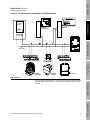
Figure 2-3. Bell 202 temporary connection to rack-mount transmitters
RFT9739
rack-mount
CN2
R4
(Note 4)
AC
Adaptor
Receive
Transmit
Power
Low Batt
Getting Started
DCS or PLC
with internal
resisitor
(Note 2)
485
202 Off 485
202
A
B
R2
HART jack
same as primary mA output
wiring circuit at left
R3
(Note 3)
D30 Z30
File Menu: Database
R1
(Note 1)
Connect two Bell 202 cables
Second Bell 202 cable
not included
RFT9729
R4
(Note 4)
CN2
AC
Receive
Transmit
Power
Low Batt
Adaptor
485
202 Off 485
202
B14
B16
A
B
File Menu: Print
HART jack same as primary mA output
wiring circuit at left
Connect two Bell 202 cables
Second Bell 202 cable
not included
Notes for Figure 2-3
1. If necessary, add resistance in the loop by installing resistor R1. SMART FAMILY devices require a minimum loop resistance of
250 ohms. Loop resistance must not exceed 1000 ohms, regardless of the communication setup.
File Menu: Log Files
CAUTION
Connecting a HART device to the transmitter’s HART jack could cause transmitter output error.
If the primary variable analog output is being used for flow control, connecting a PC interface adaptor to the HART
jack could cause the transmitter 4-20 mA output to change, which would affect flow control devices.
Set control devices for manual operation before connecting a PC interface adaptor to the transmitter’s HART jack.
minimum 250 ohms, maximum 1000 ohms. Wrap ends of resistor around prongs of plug before inserting into jack.
Using ProLink® Software with Micro Motion® Transmitters
9
View Menu: Variables
2. The DCS or PLC must be configured for an active milliamp signal.
3. Resistor R3 is required if the DCS or PLC does not have an internal resistor.
4. Resistor R4 is required if the illustrated transmitter output wiring is not connected to an input device. Required loop resistance:
Getting Started continued
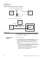
Wiring to the transmitter
Figure 2-4. Bell 202 hard-wiring to transmitters or multidrop networks
CN2
DCS or PLC
with internal
resisitor
(Note 2)
CN2
RFT9739
rack-mount
B14
B16
RFT9729
R2
D30 Z30
R3
(Note 3)
Receive
Transmit
Power
Low Batt
AC
Adaptor
485
202 Off 485
202
A
B
R1
(Note 1)
14 15 16 17 18 19 20
21 22 23 24 25 26 27
19 18 17 16 15 14
P
26 25 24 23 22 21
S
4–20mA
RFT9739
field-mount
IFT9701
IFT9703
RFT9712
Notes for Figure 2-4
1. If necessary, add resistance in the loop by installing resistor R1. SMART FAMILY devices require a minimum loop resistance of
250 ohms. Loop resistance must not exceed 1000 ohms (600 ohms for an IFT9701), regardless of the communication setup.
CAUTION
Connecting a HART device to the transmitter’s primary milliamp output loop could cause transmitter
output error.
If the primary variable analog output is being used for flow control, connecting a PC interface adaptor to the output
loop could cause the transmitter 4-20 mA output to change, which would affect flow control devices.
Set control devices for manual operation before connecting a PC interface adaptor to the transmitter’s primary
variable milliamp output loop.
2. The DCS or PLC must be configured for an active milliamp signal.
3. Resistor R3 is required if the DCS or PLC does not have an internal resistor.
10
Using ProLink® Software with Micro Motion® Transmitters
Before You Begin
Getting Started continued
Wiring to the transmitter
Figure 2-5. RS-485 hard-wiring to transmitters or multidrop networks
CN2
CN2
B14
B16
RFT9739
rack-mount
Getting Started
DCS or PLC
with internal
resistor
RFT9729
R2
D30
R3
Z30
Receive
AC
Transmit
Power
Low Batt
Adaptor
File Menu: Database
485
A
202 Off 485
202
B
R1
(See Note)
14 15
21 22
16
23
17
24
18 19
25
20
26
27
19 18 17 16 15 14
P
26 25 24 23 22 21
S
4-20 mA
IFT9701
IFT9703
File Menu: Print
RFT9739
field-mount
RFT9712
Note for Figure 2-5
11
View Menu: Variables
Using ProLink® Software with Micro Motion® Transmitters
File Menu: Log Files
For long-distance communication, or if noise from an external source interferes
with the signal, install 120-ohm, ½-watt resistors across terminals of both end
devices.
Getting Started continued
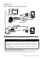
Connecting to the PC and power source
2.4
Connecting to the PC and
power source
Follow these instructions to install the PC Interface adaptor:
1. Plug the AC/DC power converter into the adaptor. Or, if desired,
install a 9-volt battery (not included) in the battery compartment on
the back of the adaptor (see Figure 2-1, page 5).
• Battery life is approximately 11 hours when the transmitter
operates at 38.4 kilobaud.
• To remove the battery compartment cover, push down on the
cover and slide it in the direction indicated by the arrow. After
installing the battery, put the battery compartment cover securely
in place on the back of the adaptor.
For use in the European community, the Micro Motion PC Interface is
CE compliant only when used with a power supply that is filtered
against electromagnetic interference. Use of a battery or the power
converter in the ProLink kit meets this requirement. To order a
replacement power converter, see Appendix A.
2. Set the selector switch on the adaptor to the center position, which
shuts off power to the adaptor.
3. Plug the adaptor into a serial port on the personal computer, as
illustrated in Figure 2-6. If necessary, install the supplied 25-pin to
9-pin converter between the serial port and the PC Interface adaptor.
4. Set the selector switch on the adaptor to the appropriate position:
• To use the Bell 202 standard, set the switch to 202.
• To use the RS-485 standard, set the switch to 485.
5. With a battery installed or the AC/DC adaptor plugged into the
adaptor and a power supply, and with the selector switch set to the
202 or 485 the adaptor is ready for use. The red light labeled "Power"
on the adaptor should be lit.
Figure 2-6. Installing the PC Interface adaptor
Back of computer
25-to-9-pin converter
(use if necessary)
12
PC Interface adaptor
Using ProLink® Software with Micro Motion® Transmitters
Installing the software
2.5
Installing the software
The ProLink kit comes with one 3½-inch diskette, which contains the
operating files for the software. Because the ProLink installation/setup
program decompresses files during installation, ProLink software cannot
be installed by copying files from the diskette to the hard drive. Run the
ProLink installation/setup program to install the ProLink software on the
personal computer hard drive.
To install the ProLink program:
1. Insert the ProLink diskette into a disk drive.
Getting Started
Before installing the program, make a back-up copy of the ProLink disk.
Before You Begin
Getting Started continued
2. Open the Windows program manager, open the File menu, then
choose Run. Windows 95 users, choose Start, then choose Run.
A:\SETUP.EXE
or
B:\SETUP.EXE
4. Follow the on-screen instructions to complete the installation
process. Consult the sections below and on the following pages, if
necessary, or contact the Micro Motion Customer Service
Department for technical assistance.
File Menu: Database
3. At the Run dialog box, depending on the drive where the ProLink
diskette has been inserted, enter one of the following commands into
the File Name text box:
File Menu: Print
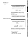
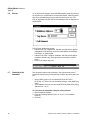
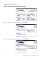
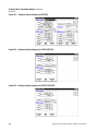
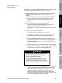
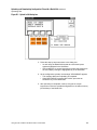
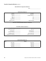
Initial Installation dialog box
The installation/setup program offers two options:
• Initial Installation, which installs the ProLink software and places
ProLink icons in a Windows program group.
• Change setup, which allows changes to device drivers for HART or
Modbus protocol and the communication port.
Using ProLink® Software with Micro Motion® Transmitters
13
View Menu: Variables
To install the ProLink software, select Initial Installation, then click OK.
File Menu: Log Files
The Initial Installation or Change Options dialog box appears as shown
above.
Getting Started continued
Installing the software
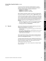
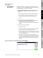
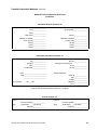
Installation Location dialog box
When the Installation Location dialog box appears as shown above,
enter the desired directory pathname, then click OK.
The installation/setup program creates the directory. As ProLink
program files are copied into the chosen directory, a "thermometer"
indicates the percentage of the installation that has been completed.
If a previous release of the ProLink program is installed on the
computer:
• The new program may be installed in the same directory as the
earlier version, or in a new directory. The new program files will
overwrite any default files that were created previously.
• The new program will use any configuration and default files that
were created using an earlier ProLink version. However, if the new
program is installed in a directory other than the default ProLink
directory, it will be necessary to locate configuration and default files
manually when using the new program.
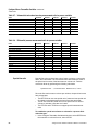
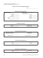
Program Group dialog box
During software installation, the Select Program Group dialog box,
shown above, prompts the user to place the icons in a group window or
submenu named MMI, or in another group window or submenu.
Enter the name of the desired group window or submenu from the Start
menu in the text box, then click OK.
14
Using ProLink® Software with Micro Motion® Transmitters
Before You Begin
Getting Started continued
Installing the software
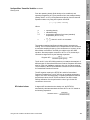
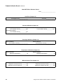
Modify/Copy CONFIG.SYS dialog box
Getting Started
Select an option, then click OK.
• Select Add/Change to add the HART or Modbus device driver to the
CONFIG.SYS file in the root directory on the hard drive.
• Select Copy to copy the CONFIG.SYS file to the ProLink directory
before adding the appropriate device driver.
File Menu: Database
After the user specifies a Windows program group, the Modify or Copy
CONFIG.SYS dialog box appears as shown above. The choice
determines how device drivers are added to the personal computer
CONFIG.SYS file.
Communications Protocol dialog box
File Menu: Print
Using ProLink® Software with Micro Motion® Transmitters
15
View Menu: Variables
Select either option, then click OK:
• Select HART or Modbus protocol if the PC Interface adaptor is
connected to an RFT9739.
• Select HART protocol if the PC Interface adaptor is connected to an
IFT9701, IFT9703, RFT9712, or an RFT9729.
File Menu: Log Files
After the user chooses how the installation/setup program modifies the
CONFIG.SYS file, the Communications Protocol dialog box appears as
shown above. The choice determines the protocol used by the software,
without affecting the protocol used by the PC Interface adaptor or the
connected transmitter.
Getting Started continued
Installing the software
After ProLink software installation is completed, the ProLink Setup icon
enables switching of protocols used by the ProLink program. To change
the protocol used by:
• The ProLink program, see Section 2.8, page 22
• An RFT9739 transmitter, see the RFT9739 instruction manual
Communications Port dialog box
After the installation/setup program establishes the protocol that the
ProLink program will use, the Communications Port dialog box appears
as shown above. The dialog box prompts the user to choose COM1 or
COM2 as the communication port.
Select the desired option, then click OK, or, if the personal computer has
more than two serial ports, and a port other than COM1 or COM2 is
desired:
1. At the Communications Port dialog box, choose COM2.
2. After installation is completed, use the Windows Notepad program to
open and read the 3COM.TXT file (located in the INST subdirectory
of the ProLink directory). The 3COM.TXT file is an ASCII file that
explains how to modify the CONFIG.SYS file to designate COM3 or
COM4 as the communication port.
16
Using ProLink® Software with Micro Motion® Transmitters
Before You Begin
Getting Started continued
Installing the software
Modify/Copy .INI files dialog box
Getting Started
Select an option, then click OK:
• Select Add/Change to add the communication port and display
parameters to the SYSTEM.INI and WIN.INI files in their default
directories on the hard drive.
• Select Copy to copy the SYSTEM.INI and WIN.INI files to the
ProLink directory before adding the communication port and display
parameters.
File Menu: Print
Setup Complete/Reboot dialog box
File Menu: Database
After the user selects a communication port, the Modify or Copy WIN.INI
and SYSTEM.INI dialog box appears as shown above. The choice
determines how the installation/setup program modifies the personal
computer SYSTEM.INI and WIN.INI files to include the user-selected
communication port and display parameters specified in the installation
process.
If CONFIG.SYS, SYSTEM.INI and WIN.INI files were copied during the
installation, copy them back to their default directories (e.g., using File
Manager or Windows Explorer), then reboot the computer.
• Copy the CONFIG.SYS file to the root directory.
• Copy the SYSTEM.INI and WIN.INI files to the Windows directory.
• It is necessary to reboot the computer to initialize changes made to
the CONFIG.SYS file.
17
View Menu: Variables
Using ProLink® Software with Micro Motion® Transmitters
File Menu: Log Files
After the user chooses how the installation/setup program modifies the
SYSTEM.INI and WIN.INI files, the Setup Complete dialog box appears
as shown above.
Getting Started continued
Start-up
2.6
Start-up
To run the ProLink program, select the MMI program group, then click on
the ProLink icon. In Windows 95, click the Start button, select Programs,
then select the MMI program group and click the ProLink icon. The
ProLink application window and Connect dialog box will be displayed, as
shown below.
In the ProLink application window:
• Labels for the File, Applications, Window, and Help menus appear
highlighted to indicate they can be accessed without a transmitter
connection, as shown below.
• Labels for the View, Configure, Calibrate, and Test menus appear
dimmed to indicate they are temporarily inaccessible, as shown
below.
• Press F1 for help at any time.
2.7
Connecting to the
transmitter
Use the option buttons and text boxes in the Connect dialog box to
identify the transmitter by polling address or HART tag name, then click
OK.
•
•
Under HART protocol, the connected RFT9739, RFT9712,
RFT9729, or IFT9701 can use the polling address or the (HART) tag
name.
Under Modbus protocol, the connected RFT9739 must use a polling
address from 1 to 15.
To connect to the transmitter using its polling address:
1. Select Multidrop Address.
2. Enter the multidrop address, from 0 to 15 (1 to 15 for Modbus
protocol).
3. Click OK.
18
Using ProLink® Software with Micro Motion® Transmitters
Before You Begin
Getting Started continued
Connecting to the transmitter
To connect to the transmitter using its HART tag name (HART
protocol only):
1. Select Tag Name.
2. Enter the transmitter tag name.
3. Click OK.
Getting Started
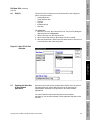
To view a list of available transmitters:
1. Select Poll Network.
2. Click Poll.
3. The network will be polled, and a drop-down list of available
transmitters is displayed, including addresses and HART tag names.
Select a transmitter, then click OK.
Menu bar
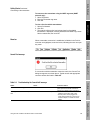
Cannot Find message
File Menu: Print
If a connection with the transmitter cannot be made, the Cannot Find
dialog box appears, as shown above. Typical causes and appropriate
corrective actions are listed in Table 2-2.
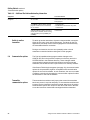
Cause
Power OFF to transmitter
Power light on PC Interface adaptor is
OFF
Power OFF on PC Interface adaptor
Corrective Action
Verify the transmitter is receiving supply
power (see the transmitter instruction
manual for troubleshooting instructions)
• Ensure selector switch on PC Interface
adaptor is set to either 202 or 485
• Ensure power cord is plugged into
power socket and firmly in place on PC
Interface adaptor, or install new 9-volt
battery
19
View Menu: Variables
Using ProLink® Software with Micro Motion® Transmitters
File Menu: Log Files
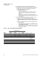
Table 2-2. Troubleshooting the "cannot find" message
Status
Transmitter not receiving power
File Menu: Database
When a transmitter connection is established, all labels in the ProLink
menu bar are highlighted, as shown below, indicating the user can open
any menu.
Getting Started continued
Connecting to the transmitter
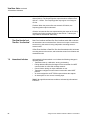
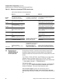
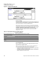
Table 2-2. Troubleshooting the "cannot find" message
Status
Transmit light on PC Interface adaptor
does not flash when trying to connect
to the transmitter
Cause
Incorrect computer communication port
Computer communication port (COMM1
or COMM2) is being used by another
program or device, such as a mouse,
fax, or modem
IRQ is being shared by ProLink and
another program or device, such as a
mouse, fax, or modem, which is using
communication port 3 (COMM3) or 4
(COMM4)
Windows 3.1 and ProLink time source in
conflict
Transmit light on PC Interface adaptor
remains OFF, and the receive light
flashes while trying to connect to
transmitter
Transmit light on PC Interface adaptor
flashes while trying to connect to
transmitter using the Bell 202 physical
layer
Using wrong type of cable between the
computer and the PC Interface adaptor
Conflict between physical layer settings
Improper wiring between PC Interface
adaptor and transmitter
Incorrect load resistance in wiring loop
Incorrect communication parameters
Noise on mA loop from an external
source
RFT9739 not properly configured for
Bell 202
RFT9712 or RFT9729 not properly
configured for Bell 202
Incompatible communication settings
between IFT9701/IFT9703 and ProLink
program
20
Corrective Action
• Change comm ports with the ProLink®
setup program
• Check cable connections between the
computer and the PC Interface adaptor
• Change comm ports with the ProLink
setup program
• Disable device and remove other
conflicting comm drivers
Disable device and remove other
conflicting comm drivers
Change the time source from Real Time
clock to Interval Timer with the ProLink
setup program
Use a straight through RS-232 cable
from the computer to the PC Interface
adaptor
Ensure that transmitter and position of
selector switch on PC Interface adaptor,
are all set to Bell 202
Ensure proper Bell 202 wiring (see
“Wiring to the transmitter” on page 7)
Ensure proper load in Bell 202 wiring
loop (see “Wiring to the transmitter” on
page 7)
Bell 202 requires HART® protocol at
1200 baud, 1 stop bit, and odd parity
(see “Communication options” on page
22, to change settings)
Ensure proper resistance in the Bell 202
wiring loop (see “Wiring to the
transmitter” on page 7)
Change RFT9739 settings (see the
instruction manual that was shipped with
the transmitter)
See the RFT9712 or RFT9729
instruction manual to verify:
• The communications jumper located
on the processor board in the
RFT9712 or RFT9729 is set to 268
• The RFT9712 or RFT9729 has
transmitter software version 5.0 or
higher
Ensure ProLink settings are configured
for HART protocol, 1200 baud, 1 stop bit,
250-600 ohm resistance and odd parity
(see “Communication options” on page
22)
Using ProLink® Software with Micro Motion® Transmitters
Before You Begin
Getting Started continued
Connecting to the transmitter
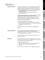
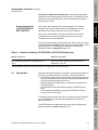
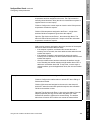
Table 2-2. Troubleshooting the "cannot find" message
Status
Transmit light on PC Interface adaptor
flashes while trying to connect to
transmitter using the RS-485 physical
layer
Cause
Conflict between physical layer settings
Incorrect communication parameters
Incorrect polling address
RFT9739 not properly configured for
RS-485
RFT9712 or RFT9729 not properly
configured for RS-485
Windows® hour glass
When the Windows hour-glass symbol does not disappear, the ProLink
program has experienced a fatal error. Reboot the computer, then refer
to Table 2-3 for typical causes and appropriate corrective actions.
File Menu: Print
Noise interference
File Menu: Database
Baud rate too high for computer
Getting Started
Improper wiring between PC Interface
adaptor and transmitter
Corrective Action
Ensure that transmitter and ProLink
setup, and position of selector switch on
PC Interface adaptor, are all set to
RS-485
• Ensure proper RS-485 wiring (see
“Wiring to the transmitter” on page 7)
• Verify terminal blocks are firmly seated
at transmitter and PC Interface adaptor
Verify that settings for protocol (HART or
Modbus®), baud rate, parity, and stop
bits are the same for the transmitter and
ProLink program
Open the File menu, then choose
Connect. Click the Poll Network button in
the Connect dialog box, then choose Poll
for a list of available transmitters
Change ProLink baud rate to 1200 baud,
then reset to higher rate is desired: Open
the File menu, then choose Comm
Options
Change RFT9739 settings (see the
instruction manual that was shipped with
the transmitter)
See the RFT9712 or RFT9729
instruction manual to verify:
• The communications jumper located
on the processor board in the
RFT9712 or RFT9729 is set to 485
• The RFT9712 or RFT9729 is using
1200 baud for HART communication,
and has transmitter software version
5.0 or higher
Ensure proper RS-485 wiring (see
“Wiring to the transmitter” on page 7)
File Menu: Log Files
21
View Menu: Variables
Using ProLink® Software with Micro Motion® Transmitters
Getting Started continued
Communication options
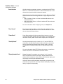
Table 2-3. Additional ProLink troubleshooting information
Symptom
Windows® hourglass symbol does not
disappear
Cause
Windows 3.1 and ProLink time source
are in conflict
Computer communication port (COMM1
or COMM2) is being used by another
program or device, such as a mouse,
fax, or modem
IRQ is being shared by ProLink and
another program or device, such as a
mouse, fax, or modem, which is using
communication port 3 (COMM3) or 4
(COMM4)
Switch to another
transmitter
Corrective Action
Change the time source from Real time
clock to Interval timer with the ProLink
setup program
• Change comm ports with the ProLink
setup program
• Disable device and remove any other
comm drivers
Disable device and remove any other
comm drivers
To switch to another transmitter, disconnect the transmitter connection.
Open the File menu, then choose Disconnect. The labels for the File,
Applications, and Help menus remain highlighted to indicate that they
are accessible without a connection.
During a work session, the user can repeatedly make or break
transmitter connections without closing the ProLink program.
2.8
Communication options
The ProLink installation/setup program makes changes to the
CONFIG.SYS file in the personal computer root directory and to the
SYSTEM.INI file in the Windows directory. These changes enable
communication between the personal computer and the connected
transmitter, and enable the user to poll devices on a multidrop network.
If the Cannot Find dialog box appears (see page 19), the communication
options for the transmitter might be incompatible with communication
options for the ProLink software. In such situations, the user can enable
a software connection by changing the communication options for either
the transmitter or the ProLink software.
Transmitter
communication options
22
The transmitter has switches and jumpers that control the transmitter
baud rate, protocol, stop bits and parity. To set transmitter switches and
jumpers, see the transmitter instruction manual. Instructions for setting
communication options are unique for each RFT9739 version. Be sure
to use the instruction manual that was shipped with the transmitter.
Using ProLink® Software with Micro Motion® Transmitters
Communication options
Software communication
options
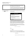
After software installation is completed, communication protocols,
communication ports, and time source may be changed with the ProLink
installation/setup program. Communication options may then be
changed using the Configure Communications dialog box.
Getting Started
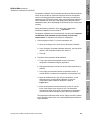
To change the configured ProLink communication setup:
1. Open the Windows Program Manager, open the MMI program group,
then double-click the ProLink Setup icon to run the ProLink setup
program. Windows 95 users select Programs from the Start menu,
then MMI (or the program group containing ProLink), then ProLink
Setup from the cascading menus.
2. When the Initial Installation or Change Options dialog box appears
as shown below, select Change setup.
Before You Begin
Getting Started continued
File Menu: Database
File Menu: Log Files
23
View Menu: Variables
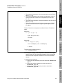
4. After using the setup program:
a. If CONFIG.SYS, SYSTEM.INI and WIN.INI files were copied
during setup, use File Manager or Windows Explorer to copy
them back to their default directories.
- Copy the CONFIG.SYS file into the root directory.
- Copy the SYSTEM.INI and WIN.INI files into the Windows
directory.
5. Reboot the computer.
Using ProLink® Software with Micro Motion® Transmitters
File Menu: Print
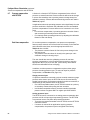
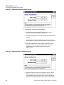
3. When the Setup Options dialog box appears as shown below, select
one or more parameters to change. Click OK, then follow the
on-screen instructions to switch protocol, port, and/or PC timer
options.
Getting Started continued
Communication options
6. Open the Windows Program Manager, open the MMI program group,
then double-click the ProLink icon to run the ProLink program.
Windows 95 users select Programs from the Start menu, then select
MMI (or the program group containing ProLink), then select ProLink
from the cascading menus.
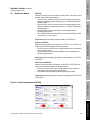
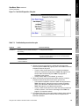
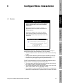
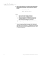
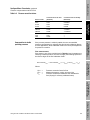
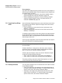
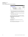
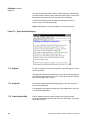
7. Open the File menu, then choose Comm Options. The
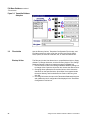
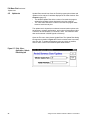
Communication Options dialog box appears as shown in Figure 2-7.
Figure 2-7. Configure Communications dialog box
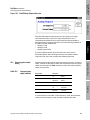
8. Open the Baud Rate list box to select a baud rate.
• Select 1200 baud for IFT9701, IFT9703, RFT9712, and RFT9729
transmitters.
• Select 1200 baud for RFT9739 transmitters configured for HART
Bell 202 communication.
• Select any baud rate for RFT9739 transmitters using HART or
Modbus RS-485 communication.
9. Comm Details shows the configured communications port and
communication hardware interrupt request line (IRQ). The port and
IRQ cannot be changed from the Configure Communications dialog
box, but must be configured in the ProLink setup routine. Follow
steps 1 through 3 to change the communications port and IRQ.
10. Select a Master Type option button. The available master types
depend on the protocol established when the software was installed:
• With the ProLink program configured for HART protocol (default),
select HART Primary or HART Secondary as the master type.
- Select HART Primary to designate the ProLink program as the
primary master for the network. Choosing HART Primary
enables the ProLink program and a secondary master, such
as a Model 268 or 275, to communicate at the same time.
- Select HART Secondary to designate the ProLink program as
the secondary master for the network. Choosing HART
Secondary enables a control system to serve as the primary
master.
24
Using ProLink® Software with Micro Motion® Transmitters
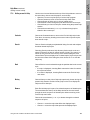
Exit
•
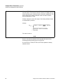
Exit
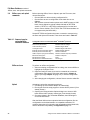
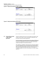
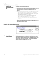
To exit the ProLink program, open the File menu, then choose Exit. The
Exit ProLink dialog box appears, as shown below.
File Menu: Database
2.9
Getting Started
With the ProLink software configured for Modbus protocol,
choose Modbus ASCII or Modbus RTU.
- If Modbus RTU (default) is chosen, the ProLink program will
use the RTU data transmission mode (8 data bits).
- If Modbus ASCII is chosen, the ProLink program will use the
ASCII data transmission mode (7 data bits). Choose this
option if the communication network cannot support binary
data.
11. For Windows 3.1 users only, Time Source shows whether the
ProLink software will use a real time clock or interval timer. The time
source cannot be changed from the Configure Communications
dialog box, but must be configured in the ProLink setup routine.
Follow steps 1 through 3 to change the time source configuration.
12. Use the Parity and Stop Bits option buttons to select the appropriate
parity and stop bits.
• Under HART protocol, the transmitter must use odd parity and
one stop bit.
• Under Modbus protocol, the transmitter can use odd parity, even
parity, or no parity, and either one or two stop bits.
13. Click OK when ready to accept the software communications
configuration.
Before You Begin
Getting Started continued
File Menu: Print
•
•
25
View Menu: Variables
Using ProLink® Software with Micro Motion® Transmitters
File Menu: Log Files
•
Select Yes to save the ProLink setup and communication options to
the PROLINK.INI file in the ProLink directory.
Select No to exit without saving the ProLink setup and
communication options.
Select Cancel to return to the ProLink program.
26
Using ProLink® Software with Micro Motion® Transmitters
File Menu: Database
Overview
The Transmitter Database dialog box, shown in Figure 3-1, page 28,
enables storage, retrieval, transfer, and editing of transmitter
configurations. To open the Transmitter Database dialog box, open the
File menu, then choose Database.
The Transmitter Database dialog box operates in the connect mode and
the offline mode. The mode determines the tasks that the user can
perform.
The user can remove a configuration file from the database at any time.
In the Transmitter Database dialog box, arrows and icons indicate the
direction of the transfer the ProLink program performs when a command
button is selected.
27
View Menu: Variables
Using ProLink® Software with Micro Motion® Transmitters
File Menu: Log Files
To disconnect from the transmitter, open the File menu, then choose
Disconnect. When disconnected, the user can:
• Edit an existing configuration file.
• Save a configuration file to the hard drive or to a floppy diskette.
• Upload a Model 268 with an RFT9739, RFT9712, or RFT9729
configuration file (the ProLink program cannot be used with a Model
275 HART Communicator).
File Menu: Print
To connect to the transmitter, open the File menu, then choose Connect.
When connected, the user can:
• Load a configuration file from the connected transmitter to the hard
drive or to a diskette.
• Send a configuration file from the hard drive or from a diskette to the
connected transmitter.
File Menu: Database
The database contains transmitter configuration files in ASCII code.
A transmitter configuration file has an 8-character filename and a .CFG
extension. The default database includes one sample transmitter
configuration file for:
• the RFT9739 (samp9739.cfg)
• the IFT9701 (samp9701.cfg)
• the IFT9703 (samp9703.cfg)
• the RFT9712 and RFT9729 (samp9712.cfg)
Getting Started
3.1
Before You Begin
3
File Menu: Database continued
File selection
Figure 3-1. Transmitter Database
dialog box
3.2
28
File selection
Use the Directory list box, Transmitter Configuration Files list box, and
File Name text box to select a file, then choose Load, Send, Offline,
Save, Upload, or Remove to transfer, edit, or erase the selected file.
Directory list box
The Directory list box lists directories on a specified hard drive or floppy
diskette. To change directories, click the Directory list box. The Change
Database Directory dialog box appears as shown in Figure 3-2.
1. Use the Drives list box in the Change Database Directory dialog box
to change drives. Open the drives list, then choose the desired drive.
2. Changing drives updates the Directories list box, which shows the
directories on the specified drive. Open folder icons appear beside
the active directory and its subdirectories. Select a directory, then
click OK.
3. Choosing OK returns the user to the Transmitter Database dialog box
and updates the list of configuration files displayed in the Transmitter
Configuration Files list box.
Using ProLink® Software with Micro Motion® Transmitters
Before You Begin
File Menu: Database continued
Database command buttons
Figure 3-2. Change Database
Directory dialog box
Getting Started
The Transmitter Configuration Files list box displays transmitter
configuration files in the active directory. Each file contains a partial or
complete configuration for an RFT9739, IFT9701, IFT9703, RFT9712, or
RFT9729.
Select a filename from the Transmitter Configuration Files list box. The
selected filename appears in the File Name list box.
File name text box
File Menu: Print
Enter the name of a transmitter configuration file in the File Name text
box. The filename can include a DOS pathname, which overrides the
currently displayed drive and directory.
Create new configuration files by using Windows Explorer or File
Manager to copy an existing configuration file, which then can be
transferred or edited.
3.3
Database command
buttons
View Menu: Variables
29
File Menu: Log Files
After selecting a configuration file, as described in Section 3.2, choose
any active command button. Arrows and icons beside the command
buttons indicate the direction of the file transfer.
• From the transmitter, load the file to the hard drive or to a diskette.
• From the hard drive or from a diskette, send the file to the transmitter.
• From the hard drive or from a diskette, retrieve the file into the
ProLink database for offline editing.
• From the ProLink database, save the file to the hard drive or to a
diskette.
• From the hard drive or from a diskette, upload the file to a Model 268
(the ProLink program cannot be used with a Model 275 HART
Communicator).
• Erase (remove) the file from the ProLink database.
Using ProLink® Software with Micro Motion® Transmitters
File Menu: Database
Transmitter configuration
files list box
File Menu: Database continued
Offline, save, and upload commands
3.4
Offline, save, and upload
commands
Before choosing Offline, Save or Upload, open the File menu, then
choose Disconnect.
• Choose Offline to edit an existing configuration file.
• Choose Save to save a configuration to the hard drive or to a
diskette.
• With software communication options set for HART primary at 1200
baud, choose Upload to upload a Model 268 with an RFT9739
version 2, RFT9712, or RFT9729 configuration file from the hard
drive or from a diskette. (The IFT9701 and IFT9703 transmitters are
not supported by the Model 268.)
Several RFT9739 configuration items are not saved or restored using
the Save and Upload commands. These items are listed in Table 3-1.
Table 3-1. Items not saved or
restored with the
transmitter database
Configuration items not saved with HART® or Modbus® protocols
Baud rate
Milliamp output trim factors
Burst mode (ON or OFF)
Modbus maximum integer
Communication protocol
Modbus integer offsets
Convergence limit
Modbus integer scale factors
External pressure transmitter polling*
Multidrop/polling address
External pressure transmitter tag
Number of data bits
HART unique ID (Long frame address) Number of HART response preambles
Maximum zeroing time
Number of stop bits
Mechanical zero offset
Parity
Mechanical zero standard deviation
Sensor type*
*Saved with HART protocol; not saved with Modbus protocol
Offline and save
To perform an offline configuration:
1. Select an existing configuration file for editing, then choose Offline to
highlight the Configure menu.
2. Open the Configure menu, then use its commands to access the
configuration dialog boxes. Follow the instructions in Chapter 8
(page 71) through Chapter 13 (page 131) to edit the configuration
file.
3. After changing the configuration, choose Save to save the edited file.
Upload
Uploading involves four separate procedures:
1. Connecting the PC Interface adaptor to a Model 268
2. Running the ProLink setup program to choose HART protocol (if not
already chosen)
3. Opening the Communication Options dialog box to choose 1200
baud and the HART primary master type (if not already chosen)
4. Choosing Upload in the Transmitter Database, then following the
on-screen instructions
After the Model 268 has been uploaded with the configuration file, the
configuration can be downloaded to a compatible transmitter. For
complete instructions for uploading and downloading with a Model 268,
and for transmitter compatibility, see Appendix B, page 171.
30
Using ProLink® Software with Micro Motion® Transmitters
Before You Begin
File Menu: Database continued
Load command
3.5
Load command
Before choosing the Load command:
1. Open the File menu, then choose Connect.
2. Set the flow loop for manual operation.
File Menu: Database
After loading is completed, the user can access the configuration with
the ProLink program.
Figure 3-3. File Overwrite dialog
box
Send command
Before choosing the Send command:
1. Open the File menu, then choose Connect.
2. Set the flow loop for manual operation.
3. Make sure the transmitter memory and the source configuration file
have the same measurement units. Otherwise, the transmitter will
refuse the configuration.
31
View Menu: Variables
Using ProLink® Software with Micro Motion® Transmitters
File Menu: Log Files
If the source configuration file includes measurement units, follow these
steps to ensure they match the measurement units already stored in the
transmitter memory.
1. Set the control loop for manual operation.
2. Load the transmitter memory into the ProLink database as instructed
in Section 3.5.
3. Open the Configure menu, then choose Transmitter Variables.
4. In the Configure Transmitter Variables dialog box, use the Units list
boxes to change the measurement units so they match the units in
the source configuration, then click OK.
File Menu: Print
3.6
Getting Started
To load a transmitter configuration into the ProLink database:
1. Open the File menu, then choose Database.
2. Select a file from the Transmitter Configuration Files list box, or type
a new configuration file name in the File Name text box. If desired,
click in the Directory box to change directories.
3. Choose Load to load the transmitter configuration into the
configuration file.
4. If the filename already exists, the Overwrite File dialog box appears,
as shown in Figure 3-3, before the configuration begins loading.
Choose Yes to proceed. The transmitter memory then overwrites the
selected configuration file.
File Menu: Database continued
Remove command
To send a configuration file to the transmitter:
1. Open the File menu, then choose Connect.
2. Select the desired transmitter, then click OK.
3. Reopen the File menu, then choose Database.
4. Use the Transmitter Database dialog box to select the configuration
file to be sent to the transmitter, then choose Send.
3.7
Remove command
The user can erase (remove) configuration files with the ProLink
program in the connect or offline mode.
To remove a configuration file from the transmitter database:
1. Open File menu, the choose Database.
2. Select the configuration file to be erased, then choose Remove.
3.8
On-screen viewing of
transmitter configuration
files
Use a text editor program, such as WordPad or Notepad, for on-screen
viewing of transmitter configuration files.
To view a transmitter configuration file:
1. Open a transmitter configuration file in WordPad or Notepad.
Transmitter configuration files are located in the default ProLink
directory, and are saved with a .CFG extension.
2. The chosen transmitter configuration file appears on screen as
depicted in Figure 3-4.
Figure 3-4. Typical transmitter
configuration file
3.9
32
Exporting transmitter
configuration files
Because transmitter configurations are stored as text files, they can
readily be imported into spreadsheets, word processors, and other
software applications. For more information about importing files, see
the documentation for the application that will receive the configuration.
Using ProLink® Software with Micro Motion® Transmitters
File Menu: Print
Overview
The File menu includes several commands used for retrieving process
information from one or more devices on a multidrop network and
sending the information to a printer or to an ASCII file. If the information
goes to a file, the data in the file can be imported into spreadsheets,
databases, word processors, and other software applications.
4.2
Print setup
Open the File menu, then choose Print Setup. The Print Setup/Ticket
Builder dialog box appears, as shown in Figure 4-1, page 34.
Using ProLink® Software with Micro Motion® Transmitters
33
View Menu: Variables
The user can define and store any number of ticket definition files. The
ProLink software saves ticket definition file names with a .TKT extension.
File Menu: Log Files
The Print Setup/Ticket Builder dialog box allows the user to create a
ticket definition file with the following information:
• Destination determines where the polled data will be stored. Data
may be sent to a printer or written to an ASCII file.
• Transmitter Connections specify which transmitters are to be
polled. Up to 15 transmitters per ticket definition file can be specified.
• Fields on Ticket specifies fields, for each transmitter, that are to be
sent to the defined destination. A single ticket can include up to 100
data fields.
• Separator defines the delimiter for fields on the ticket. The delimiter
is used to separate fields in a file for importation into other software
applications (such as spreadsheets and databases).
• Book Ends define the text that will print at the beginning and end of
each print cycle.
File Menu: Print
Use the Print Setup/Ticket Builder dialog box to create a ticket definition
file. The ticket definition file specifies which transmitters the ProLink
program will poll, which data will be sent to the print ticket, and the
format of the print ticket.
File Menu: Database
The File menu includes the following print commands:
• Choose Print Setup to define any number of tickets, which can
include data from transmitters and other HART 5.0 or higher revision
devices on a multidrop network. The ticket can go to a printer or to an
ASCII file.
• Choose Print to send one copy of a ticket to a printer or an ASCII file.
• Toggle the Interval Print command ON to send a ticket to the printer
or to the file at regular intervals controlled by the refresh rate.
• Choose Update Rate to set the print interval for tickets and the
update rate for all ProLink windows.
• Choose Print File to send a selected file to the connected printer.
Getting Started
4.1
Before You Begin
4
File Menu: Print continued
Print setup
Figure 4-1. Print Setup/Ticket
Builder dialog box
Select, edit, or create a
ticket definition file
The Ticket File text box shows the ticket definition file name.To select,
edit, or create a ticket definition file, other than the displayed definition:
1. Click the Ticket File text box. The ticket File Name dialog box
appears as depicted in Figure 4-2.
2. When the Ticket File Name dialog box appears:
• To select or edit an existing ticket definition file, select the desired
drive and directory, then double-click the desired filename.
• To create a new ticket definition file, select a drive and directory,
enter a new filename in the File Name text box, then click OK.
Figure 4-2. Ticket File Name
dialog box
34
Using ProLink® Software with Micro Motion® Transmitters
Print setup
Destination
Destination options enable the ticket to go to a printer or to an ASCII text
file. If the ticket will go to a file, the user may name the ASCII text file that
will receive the data specified by the ticket definition.
Transmitter connections
To add a device to the ticket definition file:
1. Choose Add in the Transmitter Connections frame. The Add
Transmitter Tag dialog box appears as shown in Figure 4-3.
File Menu: Print
The first time a ticket is printed, the ProLink program checks for all
transmitter connections that are listed in the ticket definition file. If any
connection fails, the ticket will not print, and an error message will
appear. If the ticket definition file includes [CurCon], the ProLink program
must be in the connect mode.
File Menu: Database
The Transmitter Connections list box displays all transmitter devices that
will be polled for the data to be printed on the ticket. The ticket definition
file may include up to 15 devices on a multidrop network, including the
currently connected transmitter.
• Under HART protocol, the currently connected transmitter can be
referred to as the special tag name "[CurCon]", as well as by its
established HART tag name or polling address.
• Under Modbus protocol, the currently connected transmitter can be
referred to by the special tag name "[CurCon]" or the polling address.
Getting Started
Click an option button to choose a destination.
• If the ticket will go to an ASCII text file, enter the desired filename in
the text box. Do not enter a DOS pathname. Ticket text files are
saved to the default ProLink directory with a .TXT extension.
• If desired, column headings can be added to the ticket by selecting
the Use Column Headings checkbox. This option is overridden if
Field Name is chosen as a separator (see “Separator and book
ends” on page 37).
Before You Begin
File Menu: Print continued
Figure 4-3. Add Transmitter Tag
dialog box
File Menu: Log Files
35
View Menu: Variables
Using ProLink® Software with Micro Motion® Transmitters
File Menu: Print continued
Print setup
2. At the Add Transmitter Tag dialog box, use the Tag Name option
buttons to select a device. If a device other than the connected
transmitter [CurCon] is selected, enter the polling address or HART
tag name in the text box. A device cannot be added to the ticket
definition file if a device with the same tag name already exists in the
file.
3. Use the Transmitter Type option buttons to specify one of three
available transmitter types:
• Select RFT9739 to poll for parameters available from an
RFT9739. When using Modbus protocol, select this option for all
devices on the ticket.
• Select RFT9712/9729/9739 to poll under HART protocol for
parameters common to all three transmitter models.
• Select IFT9701 to poll for parameters available from an IFT9701
or IFT9703.
• Select Other HART v.5 or higher to poll for parameters available
from transmitters or other devices that have HART 5.0 or higher
revision software.
4. Click OK to add the device to the ticket.
To remove a device from the ticket: in the Transmitter Connections
frame, select the device from the Tag Names list, then choose Remove.
When a device is removed from a ticket, the fields associated with the
device are also removed.
Fields on ticket
To add a parameter to a device on the ticket:
1. Choose Add in the Fields on Ticket frame. The Edit Field Tag
Parameter dialog box appears as shown in Figure 4-4.
2. Select a device from the Tag Name text box. Each device includes
the polling address or HART tag name, followed by the transmitter
type in brackets.
3. All the parameters available from the chosen device appear in the
Parameter list box. To add a parameter, select it, then click OK.
Figure 4-4. Edit Field Tag
Parameter dialog box
36
Using ProLink® Software with Micro Motion® Transmitters
Print setup
In the Print Setup/Ticket Builder dialog box, the Fields on Ticket list box
shows parameters listed with alphanumeric codes.
• The polling address or tag name to the left of the decimal point
identifies the device that returns the parameter.
• The label to the right of the decimal point identifies the parameter.
Identify a parameter returned from an RFT9739 that has the HART tag
name ELITEFLO.
The Fields list box includes the following parameter:
ELITEFLO.216 MA_1_Var
Getting Started
Example:
Before You Begin
File Menu: Print continued
The characters to the left of the decimal point indicate the HART tag
name (ELITEFLO). The digits to the right of the decimal point indicate
that the parameter is the primary milliamp output variable.
File Menu: Database
Example:
Identify a parameter returned from an RFT9712 that has 10 as its
polling address.
The Fields list box includes the following parameter:
10.171
Flow_Cal
To remove a parameter from a device on the ticket: In the Fields on
Ticket frame, select a parameter from the Fields list, then choose
Remove.
Separator and book ends
The separator should be selected based on the ticket destination.
•
•
Using ProLink® Software with Micro Motion® Transmitters
37
View Menu: Variables
Select Field Name to print each field on a separate line (typically
used if the ticket destination is defined as Printer). Figure 4-5, page
39 shows a typical ticket printed with the fieldname as the separator.
For ASCII text files that will be imported into other software
applications, determine the appropriate separator by referring to the
instruction manual for the application into which the data will be
imported.
File Menu: Log Files
The Separator separates the various fields on the ticket. The user can
place any of the following separators between fields:
• A space
• A comma
• The field name (such as, "Mass_Flow =")
• A custom separator (such as ASCII characters, date, fieldname, etc.)
File Menu: Print
The digits to the left of the decimal point indicate the polling address
(10). The digits to the right of the decimal point indicate that the
parameter is the flow calibration factor.
File Menu: Print continued
Print
Click an option button to choose a separator. If Other is chosen, the user
can enter text as ASCII printable characters, and can also enter ASCII
decimal codes for nonprintable characters such as a carriage return
(013) or line feed (010). The ASCII character set is listed in Appendix D,
page 181.
Book Ends indicate the beginning and end of each print interval. Enter
characters for each book end as ASCII printable characters and/or
ASCII decimal codes.
To include the date, time, or fieldname as a separator or book end, enter
the following character strings:
\DATE
\TIME
\FIELDNAME
To enter the time, date, and fieldname on the same line with spaces
between them, enter a space before entering the next character string.
For example:
\DATE \TIME \FIELDNAME
To enter ASCII decimal codes for nonprintable characters:
• Enter the 3-digit decimal code for each character. The ASCII
character set is shown in Appendix D.
• Enter a backslash character (\) before each 3-digit code.
• The ASCII codes for carriage return (013) and line feed (010)
separate lines of text in most software applications. To make a new
line, enter \013\010.
• To enter a backslash as a printable character, enter two backslash
characters (\\).
Figure 4-5, page 39 shows a typical ticket printed with the leading book
end:
START TICKET \DATE \TIME
and the trailing book end:
END TICKET \013\010
4.3
38
Print
The Print command sends one complete ticket to a printer or ASCII text
file. Figure 4-5 depicts a simple ticket as it appears when the user
chooses the Print command.
• The ticket will print in accordance with the current ticket definition,
displayed in the Print Setup/Ticket Builder dialog box.
• To choose, edit, or create a ticket definition file, see Section 4.2,
page 33.
• To print a ticket, open the File menu, then choose Print.
Using ProLink® Software with Micro Motion® Transmitters
Before You Begin
File Menu: Print continued
Interval print
Figure 4-5. Typical ticket printed using print command
4.4
Interval print
To toggle the Interval Print command ON or OFF, open the File menu,
then choose Interval Print.
• If a checkmark appears beside the command line when the File
menu opens, choosing Interval Print toggles interval printing OFF.
• If the command line appears without a checkmark when the File
menu opens, choosing Interval Print toggles interval printing ON.
• Interval print is suspended while menus are open.
File Menu: Database
With Interval Print command toggled ON, the ProLink program sends
the ticket to the printer or ASCII text file at regular intervals. At each
interval, if the ticket goes to an ASCII text file, the new ticket appends to
the end of the existing file.
• The printer receives the ticket that is named in the Ticket File text box
of the Print Setup/Ticket Builder dialog box.
• To choose, edit, or create a ticket definition file, see Section 4.2,
page 33.
Getting Started
Start ticket 7/10/96 3:25:15 PM
Mass_Flow = 21.9
Temp = 25.9
Dens = 0.04561
End ticket
Figure 4-6 depicts a sample ticket as it appears when the user toggles
interval printing ON.
File Menu: Print
Figure 4-6. Typical ticket printed using interval print command
Start ticket 7/10/96 3:25:15 PM
Mass_Flow = 21.9
Temp = 25.9
Dens = 0.04561
End ticket
File Menu: Log Files
Start ticket 7/10/96 3:26:15 PM
Mass_Flow = 21.6
Temp = 25.9
Dens = 0.04561
End ticket
Start ticket 7/10/96 3:27:15 PM
Mass_Flow = 21.0
Temp = 25.9
Dens = 0.04561
End ticket
39
View Menu: Variables
Using ProLink® Software with Micro Motion® Transmitters
File Menu: Print continued
Update rate
4.5
Update rate
Update Rate controls how often the ProLink program prints tickets and
updates on-line values of variables displayed in the View windows. See
Chapter 6 (page 47).
• The Window Update Rate is the number of seconds the program
waits before updating values displayed in the View windows.
• The Ticket Print Rate is the number of seconds the program waits
between each interval print.
The update rate is dependent on selected communication options such
as baud rate, computer performance, and number of parameters polled.
Therefore, the rate entered is a "minimum" value. The maximum value
that can be entered is 86,400 (equal to 24 hours).
Open the File menu, then choose Update Rate. The Update Rate dialog
box appears as shown in Figure 4-7. Enter the desired rates in seconds,
then click OK. To update the displayed value as quickly as possible,
enter a value of zero in the Window Update Rate text box.
Figure 4-7. Print - View Application - Update
Rate dialog box
40
Using ProLink® Software with Micro Motion® Transmitters
Before You Begin
File Menu: Print continued
Print file
4.6
Print file
To print a file:
1. Open the File menu, then choose Print File. The Print File dialog box
appears as shown in Figure 4-8.
2. Select a file type from the drop-down list.
3. Select a drive and directory, then select a file to be printed.
4. When the desired file is listed in the File Name text box, choose Print
to send the file to the connected printer.
Getting Started
Use the Print File command to send a selected file to the configured
printer. File types include:
• Configuration files
• Ticket definition files
• Text files
• Log files
• Initialization files
• Data files
File Menu: Database
Figure 4-8. Select File To Print
dialog box
File Menu: Print
Exporting print ticket files
to other software
applications
Because a print ticket text file contains data in ASCII code, the ticket or
individual fields from a ticket ASCII text file can be imported into
spreadsheets, databases, word processors, and other software
applications.
For more information about exporting data to other software
applications, see the documentation for the application that will receive
the data.
41
View Menu: Variables
Using ProLink® Software with Micro Motion® Transmitters
File Menu: Log Files
4.7
42
Using ProLink® Software with Micro Motion® Transmitters
File Menu:
Error and Change Log Files
Error logging
An error log is a record of transmitter configuration changes, data entry
errors, faults, and changes in the operating condition of the flowmeter.
With error logging toggled ON, the ProLink program reports the selected
errors whenever they occur.
Getting Started
5.1
Before You Begin
5
Figure 5-1 depicts a typical error log file.
Figure 5-1. Typical error log file
To set up an error log, open the File menu, then choose Error Log File.
The Error Log dialog box appears as shown in Figure 5-2.
File Menu: Database
7/15/96 2:53:55 PM Transmitter Status Changed: POWER RESET Set
7/21/96 8:32:06 AM UPDATE: Error Sending Visc_Cal
7/30/96 0:58:30 PM UPDATE: Error Sending Slug_Duration
Figure 5-2. Error Log dialog box
File Menu: Print
In the Error Log dialog box, the Log File Name frame contains option
buttons and a text box, which enable the error log to go to a printer or to
an ASCII file. If the error log will go to a file, the text box indicates the
name the ASCII file that will receive the data in the log.
Click an option button to choose a destination. If the error log will go to
an ASCII file, enter a filename in the text box. A pathname may also be
entered. Log files are saved with a .LOG default extension.
43
View Menu: Variables
Using ProLink® Software with Micro Motion® Transmitters
File Menu: Log Files
Log file name
File Menu: Error and Change Log Files continued
Change logging
Error log options
Use the Error Log Option check boxes to set the options for the error log
file. A check box indicating an active option contains an "X".
Click check boxes to toggle options ON or OFF.
Error log on
ON: The ProLink program reports errors whenever they occur. If the
user opens the File menu with error logging toggled ON, a
checkmark appears beside the Error Log File command line.
If Error Log is turned ON, the Transmitter Status window must be
active for faults to be properly logged. The window may be
minimized if desired, but no transmitter faults will be logged with
the window closed. To view the Status window, open the View
menu, then choose Transmitter Status.
OFF: The program does not report errors. With error logging toggled
OFF, the Error Log File command appears without a checkmark.
Clear error log file
ON: Each report erases the existing error log file and starts appending
the error log file.
OFF: Each report appends the error log file.
Log transmitter faults
ON: The ProLink program reports all changes that the user can
observe in the Status window.
OFF: The program does not report changes that the user can observe
in the Status window.
Log communication errors
ON: The ProLink program reports communication errors between
ProLink and the slave device.
OFF: The program does not report data entry errors.
Log configuration errors
ON: The ProLink program reports all errors made during entry of data
into dialog boxes in the Configure menu.
OFF: The program does not report configuration errors.
5.2
Change logging
A change log is a record of changes and data entry errors made in
dialog boxes in the Configuration menu. With change logging toggled
ON, if the user makes any changes or data entry errors while working in
the Configuration menu, the ProLink program updates the change log.
Figure 5-3 depicts a typical change log file.
44
Using ProLink® Software with Micro Motion® Transmitters
Before You Begin
File Menu: Error and Change Log Files continued
Change logging
Figure 5-3. Typical change log file
PM XMTR_1 .Dens_A= 0.00110
PM XMTR_1 .Dens_B= 0.09980
PM XMTR_1 .Flow_Cal=0000.75.13
PM XMTR_1 .SlugLow= 0.0050
PM XMTR_1 .SlugHigh= 0.1000
PM UPDATE: Completed Successfully
PM XMTR_1 .Vol_Flow_Unit=USgpm
PM XMTR_1 .Visc_Unit=cP
PM XMTR_1 .DP_Unit=psi
PM XMTR_1 .Mass_Flow_Unit=kg/hr
PM XMTR_1 .Meter_Direction=Bi-Directional
PM UPDATE: Completed Successfully
PM XMTR_1 .Freq_Var=Volume Flow
PM XMTR_1 .Fault_Ind=Upscale
PM XMTR_1 .Slug_Duration=100.00
PM UPDATE: Error Sending Slug_Duration
PM XMTR_1 .mA_2_Zero= 0.00250
PM XMTR_1 .mA_2_Gain= 0.2500
PM XMTR_1 .mA_2_Damp= 8.00
PM XMTR_1 .mA_1_Damp= 2.00
UPDATE: Completed Successfully
File Menu: Database
5:47:06
5:47:06
5:47:06
5:47:06
5:47:06
5:47:09
5:48:21
5:48:21
5:48:21
5:48:21
5:48:21
5:48:26
5:49:51
5:49:51
5:49:51
5:49:52
5:50:54
5:50:54
5:50:54
5:50:54
5:50:55
Getting Started
7/15/96
7/15/96
7/15/96
7/15/96
7/15/96
7/15/96
7/15/96
7/15/96
7/15/96
7/15/96
7/15/96
7/15/96
7/15/96
7/15/96
7/15/96
7/15/96
7/15/96
7/15/96
7/15/96
7/15/96
7/15/96
To set up a change log, open the File menu, then choose Change Log
File. The Change Log dialog box appears as shown in Figure 5-4.
Figure 5-4. Change Log dialog box
File Menu: Print
In the Change Log dialog box, the Log File Name frame contains option
buttons and a text box, which enable the change log to go to a printer or
to an ASCII file. If the change log will go to a file, the text box indicates
the name the ASCII file that will receive the data in the log.
Click an option button to choose a destination. If the change log will go
to an ASCII file, enter a filename in the text box. A pathname may also
be entered. If no pathname is specified, the file will be saved in the
ProLink default directory.
45
View Menu: Variables
Using ProLink® Software with Micro Motion® Transmitters
File Menu: Log Files
Log file name
Change log options
Use the Change Log check boxes to set the options for the change log
file. A check box indicating an active option contains an "X".
Click check boxes to toggle options ON or OFF.
Change log on
ON: The ProLink program reports configuration changes and data
entry errors whenever they occur. If the user opens the File menu
with change logging toggled ON, a checkmark appears beside
the Change Log File command line.
OFF: The program does not report configuration changes or data entry
errors. With change logging toggled OFF, the Change Log File
command appears without the checkmark.
Clear change log file
ON: Each report erases the existing change log file and starts
appending the change log file.
OFF: Each report appends the change log file.
Log configuration changes
ON: The ProLink program reports changes that the user enters into
the dialog boxes in the Configure menu.
OFF: The program does not report configuration changes.
Log update errors
ON: The ProLink program reports configuration errors that the user
enters into the dialog boxes in the Configure menu.
OFF: The program reports configuration changes, but does not report
configuration errors.
46
Using ProLink® Software with Micro Motion® Transmitters
View Menu: Variables
Overview
The View menu opens windows rather than dialog boxes. Open the View
menu to read process variables, outputs, and flowmeter status
indicators.
• Choose Process Variables to read values of process variables.
• Choose Output Levels to read output levels and corresponding
output variables.
6.2
Process variables window
File Menu: Print
RFT9739
With the ProLink program connected to an RFT9739, the process
variables window can indicate:
• Mass flow rate
• Mass total
• Mass inventory
• Volume flow rate
• Volume total
• Volume inventory
• Density
• Temperature
• Viscosity
• Differential pressure (DP)
File Menu: Database
The flowmeter configuration determines the values of outputs displayed
in the Output Levels window. The update rate determines how often the
displayed values are updated.
Getting Started
6.1
Before You Begin
6
Indication of viscosity and differential pressure requires a DP cell that
measures pressure drop across the sensor.
Figure 6-1 depicts the Process Variables window for an RFT9739.
•
•
•
•
Mass flow rate or volume flow rate
Mass total (inventory) or volume total (inventory)
Density
Temperature
Using ProLink® Software with Micro Motion® Transmitters
47
View Menu: Variables
Figure 6-2 depicts the Process Variables window for an IFT9701 or
IFT9703. Figure 6-3 depicts the Process Variables window for an
RFT9712 or RFT9729.
File Menu: Log Files
IFT9701, IFT9703, RFT9712, and RFT9729
With the ProLink program connected to an IFT9701, IFT9703, RFT9712,
or RFT9729, the process variables window can indicate:
View Menu: Variables continued
Process variables window
Figure 6-1. Process variables window for RFT9739
Figure 6-2. Process variables window for IFT9701/IFT9703
Figure 6-3. Process variables window for RFT9712/RFT9729
48
Using ProLink® Software with Micro Motion® Transmitters
Output levels window
6.3
Output levels window
Getting Started
RFT9739
With the ProLink program connected to an RFT9739, the Output Levels
window displays the following values:
• The 0-20 mA or 4-20 mA current level and corresponding flow rate,
density, temperature, differential pressure, or viscosity indicated by
milliamp output 1
• The 0-20 mA or 4-20 mA current level and corresponding flow rate,
density, temperature, differential pressure, or viscosity indicated by
milliamp output 2
• The frequency and corresponding flow rate indicated by the
frequency/pulse output
• The ON/OFF status of events, which can be tied to milliamp outputs
or to the 0/15 V control output
Before You Begin
View Menu: Variables continued
Figure 6-4 depicts the Output Levels window for an RFT9739.
File Menu: Database
IFT9701 or IFT9703
With the ProLink program connected to an IFT9701 or an IFT9703, the
Output Levels window displays the following values:
• The 4-20 mA current level and corresponding flow rate as indicated
by the milliamp output
• The frequency and corresponding totalizer value indicated by the
frequency/pulse output
Figure 6-5 (page 50) depicts the Output Levels window for an IFT9701
or IFT9703.
File Menu: Print
RFT9712 and RFT9729
With the ProLink program connected to an RFT9712 or RFT9729, the
Output Levels window displays the following values:
• The 4-20 mA current level and corresponding flow rate, density, or
temperature indicated by the milliamp output
• The totalizer value indicated by the frequency/pulse output
Figure 6-6 (page 50) depicts the Output Levels window for an RFT9712
or RFT9729.
49
View Menu: Variables
Using ProLink® Software with Micro Motion® Transmitters
File Menu: Log Files
Figure 6-4. Output Levels window for RFT9739
View Menu: Variables continued
Copying displayed values to other software applications
Figure 6-5. Output Levels window for IFT9701 or IFT9703
Figure 6-6. Output Levels window for RFT9712/9729
nch
6.4
Copying displayed values
to other software
applications
Values from display boxes in the Process Variables and Output Levels
windows can be copied or linked to spreadsheets, databases, word
processors, and other software applications.
In the other application, the copied value can be pasted as ASCII text, or
linked to the ProLink window using a dynamic data exchange (DDE) link.
Links may be established from as many of the fields in the Process
Variables and Output Levels windows as desired.
After a DDE link is established, linked values are continuously updated
in the other application as long as the linked ProLink windows remain
open. The linked windows may be minimized, but when one is closed, all
DDE links from the closed window are broken. For information on
reestablishing DDE links, see the documentation for the other software
application.
50
Using ProLink® Software with Micro Motion® Transmitters
Copying displayed values to other software applications
To copy or link text from the ProLink window: move the mouse
pointer to the desired value. When the pointer changes to a cross hair
(+), click the mouse to copy the value. A Copy/Link dialog box appears
as depicted in Figure 6-7. Choose OK to copy the value.
Getting Started
Figure 6-7. Copy or Link dialog
box
Before You Begin
View Menu: Variables continued
To paste ASCII text in another application: place the insertion point
where the text should be pasted in the document, then open the Edit
menu and choose Paste.
File Menu: Database
To establish a DDE link: place the insertion point where the linked text
should be pasted in the document, then open the Edit menu and choose
Paste Special or Paste Link.
• After choosing Paste Special, choose Link as an option.
• Choosing Paste Link, if the option is available, automatically
establishes the DDE link.
Some software applications do not support DDE links. For more
information on linking data, see the documentation for the other software
application.
File Menu: Print
File Menu: Log Files
51
View Menu: Variables
Using ProLink® Software with Micro Motion® Transmitters
52
Using ProLink® Software with Micro Motion® Transmitters
View Menu: Status
Overview
The Status window indicates operating conditions. When used with tools
such as a digital multimeter (DMM), the transmitter diagnostic LED, and
fault output levels, the Status window facilitates flowmeter
characterization, calibration, testing, and troubleshooting.
Configure Menu:
Transmitter Variables
To open the Status window, open the View menu, then choose
Transmitter Status. The Status window appears as depicted in:
• Figure 7-1 for an RFT9739
• Figure 7-2 for an IFT9701 or IFT9703
• Figure 7-3 for an RFT9712 or RFT9729
The Status window has separate frames for critical, operational, and
informational indicators.
• Critical indicators are described in Section 7.3, page 56.
• Operational indicators are described in Section 7.4, page 62.
• Informational indicators are described in Section 7.5, page 66.
When a status indicator switches ON, refer to Table 7-1, page 54, which
lists status indicators alphabetically and lists the pages where
troubleshooting procedures for each indicator are described. Use the
Status window, transmitter fault output levels, and a digital multimeter
(DMM) to troubleshoot the flowmeter.
Configure Menu:
Transmitter Outputs
Status indicators aid in troubleshooting the flowmeter. When
troubleshooting, investigate critical indicators first, then check
operational and informational indicators.
• When an indicator switch is OFF, the accompanying message
appears dimmed.
• When an indicator switch is ON, the accompanying message
appears highlighted to indicate a particular condition.
Configure Menu:
Transmitter Information
CAUTION
During troubleshooting, the transmitter
could produce inaccurate flow signals.
53
Configure Menu: Events
• Set control devices for manual operation before
troubleshooting the flowmetering system.
• If terminal blocks or wiring are disconnected from the
transmitter during troubleshooting, cycle power to the
transmitter after reconnecting terminal blocks or
wiring.
Using ProLink® Software with Micro Motion® Transmitters
Configure Menu:
Characterize
7.1
View Menu: Status
7
View Menu: Status continued
Overview
Table 7-1. Status indicators
Status indicator pages
Status indicator pages
0 deg cal failed . . . . . . . . . . . . . 57
200 deg cal failed . . . . . . . . . . . 57
Analog 1 fixed . . . . . . . . . . . . . . 64, 69
Analog 1 saturated . . . . . . . . . . 64
Analog 2 fixed . . . . . . . . . . . . . . 64, 69
Analog 2 saturated . . . . . . . . . . 64
Analog input error . . . . . . . . . . . 62
Analog output fixed . . . . . . . . . . 64, 69
Analog output saturated . . . . . . 64
Burst Mode . . . . . . . . . . . . . . . . 69
Calibration failure. . . . . . . . . . . . 57, 62
Calibration in progress. . . . . . . . 67
Data loss possible . . . . . . . . . . . 62
Density overrange . . . . . . . . . . . 57
Display readback error. . . . . . . . 70
Drive overrange . . . . . . . . . . . . . 57
(E)EPROM checksum . . . . . . . . 57
Error cleared . . . . . . . . . . . . . . . 70
Event 1 on . . . . . . . . . . . . . . . . . 70
Event 2 on . . . . . . . . . . . . . . . . . 70
Frequency output fixed . . . . . . . 69
Frequency output saturated. . . . 65
Frequency saturated . . . . . . . . . 65
Input overrange . . . . . . . . . . . . . 57
Mass flow overrange . . . . . . . . . 57
Not configured . . . . . . . . . . . . . . 57
Power reset . . . . . . . . . . . . . . . . 70
Pressure input failure. . . . . . . . . 62
RAM error . . . . . . . . . . . . . . . . . 57
Raw elec. zero overflow. . . . . . . 66
Raw flow overflow . . . . . . . . . . . 66
RTD failure. . . . . . . . . . . . . . . . . 57
RTI failure . . . . . . . . . . . . . . . . . 57
Security breach . . . . . . . . . . . . . 70
Sensor failure . . . . . . . . . . . . . . 57
Slug flow . . . . . . . . . . . . . . . . . . 63
Temperature overrange . . . . . . . 57
Transmitter failiure . . . . . . . . . . . 56
Transmitter initializing . . . . . . . . 67
Volume flow overrange . . . . . . . 57
Zero too high . . . . . . . . . . . . . . . 67
Zero too low . . . . . . . . . . . . . . . . 67
Zero too noisy . . . . . . . . . . . . . . 67
Figure 7-1. Status window for RFT9739
54
Using ProLink® Software with Micro Motion® Transmitters
View Menu: Status
View Menu: Status continued
Overview
Figure 7-2. Status window for IFT9701/IFT9703
Configure Menu:
Characterize
Configure Menu:
Transmitter Variables
Figure 7-3. Status window for RFT9712/RFT9729
Configure Menu:
Transmitter Outputs
Configure Menu:
Transmitter Information
55
Configure Menu: Events
Using ProLink® Software with Micro Motion® Transmitters
View Menu: Status continued
Fault outputs
7.2
Fault outputs
If a flowmeter failure occurs, transmitters produce fault outputs. Model
RFT9739, IFT9701, IFT9703, RFT9712, and RFT9729, produce
downscale or upscale outputs to indicate a fault. In addition, a Version 2
or earlier RFT9739 also has last measured value and internal zero fault
levels.
• To set downscale or upscale fault output levels for a Version 3
RFT9739, an IFT9701, an IFT9703, an RFT9712, or an RFT9729,
refer to the transmitter instruction manual.
• To set fault levels for a Version 2 or earlier RFT9739, open the
Configure menu, then choose Transmitter Outputs.
RFT9739
• Downscale: milliamp outputs go to 0 mA if they produce a 0-20 mA
current, or to 0-2 mA if they produce a 4-20 mA current;
frequency/pulse output goes to 0 Hz.
• Upscale: milliamp outputs go to 22-24 mA; frequency/pulse output
goes to 15-19 kHz.
• Last measured value (not available with Version 3 transmitters):
Outputs hold the values measured immediately before the fault
condition occurred.
• Internal zero (not available with Version 3 transmitters): Outputs
indicate a value of zero for the represented process variable.
IFT9701/IFT9703
• Downscale: The milliamp output goes to 2 mA; the pulse output goes
to 0 Hz.
• Upscale: The milliamp output goes to 22 mA; the pulse output goes
to 7200 Hz for version 1.2 and higher or 1200 Hz for lower versions.
RFT9712/RFT9729
• Downscale: The milliamp output goes to 2 mA; the frequency/pulse
output goes to 0 Hz.
• Upscale: The milliamp output goes to 22 mA; the frequency/pulse
output goes to 11,520 Hz.
7.3
56
Critical indicators
Critical indicators switch ON under the following conditions:
• Master reset defaults in transmitter software
• Transmitter failure
• Flow, temperature, or density outside sensor limits
• Faulty flowmeter wiring, cable, or connections
• Inappropriate density calibration factors
• Plugged or partially plugged flow tubes
• Loss of input signal (when pressure is enabled)
• Temperature calibration failed (RFT9712 and RFT9729 only)
• Data loss during configuration
Using ProLink® Software with Micro Motion® Transmitters
Critical indicators
Transmitter failure
indicators
If one or more of the following indicators switches ON, a transmitter
failure has occurred:
• "Transmitter Failure"
• "(E)EPROM Checksum"
• "RAM Error"
• "RTI Failure"
• "0 Deg Cal Failure"
• "200 Deg Cal Failure"
Configure Menu:
Transmitter Variables
If a master reset is performed on the transmitter, Not Configured
switches ON to indicate the flowmeter requires complete
characterization and reconfiguration. A master reset returns all
transmitter options to their default factory values.
• To perform a master reset, refer to the transmitter instruction manual.
• To characterize the flowmeter, open the Configure menu, then
choose Characterize. For more information about characterization,
see Chapter 8 (page 71).
If any of these errors occur, contact the Micro Motion Customer
Service department.
CAUTION
Configure Menu:
Transmitter Outputs
During troubleshooting, the transmitter could
produce inaccurate flow signals.
• Set control devices for manual operation before
troubleshooting the flowmetering system.
• If terminal blocks or wiring are disconnected from the
transmitter during troubleshooting, cycle power to the
transmitter after reconnecting terminal blocks or
wiring.
Sensor failure and
overrange indicators
Configure Menu: Events
57
Configure Menu:
Transmitter Information
If a sensor failure occurs, if the sensor cable is faulty, or if measured flow,
measured temperature, or measured density goes outside the sensor
limits, one or more of the following indicators switches ON:
• "Sensor Failure"
• "RTD Failure"
• "Drive Overrange"
• "Input Overrange"
• "Temperature Overrange"
• "Mass Flow Overrange"
• "Volume Flow Overrange"
• "Density Overrange"
Using ProLink® Software with Micro Motion® Transmitters
Configure Menu:
Characterize
"Not Configured"
View Menu: Status
View Menu: Status continued
View Menu: Status continued
Critical indicators
To troubleshoot these status indicators, follow these steps:
1. Wiring problems are often incorrectly diagnosed as a faulty sensor.
At initial startup of the transmitter, always check the following:
a. Proper cable, and use of shielded pairs
b. Proper wire termination
• Wires on correct terminals
• Wires making good connections at transmitter terminals
(Table 7-2 lists terminal designations for Micro Motion
sensors)
• Wires properly connected at any intermediate terminal
junction, such as the junction box between a Model DT sensor
and transmitter
2. For a Version 3 RFT9739, follow steps 2a through 2b. For earlier
versions, and for other transmitter models, go to step 3.
a. Open the Test menu, then choose Test Points. The Test Point
Diagnostics dialog box appears, as depicted in Figure 7-4, page
59.
b. Compare the displayed values with the values listed below and
proceed as follows:
• If the displayed drive gain exceeds 8 V, see Table 7-3, page
59 to troubleshoot the problem.
• If the displayed value for the left or right pickoff does not equal
approximately 0.0034 V per Hz, based on the displayed tube
frequency, go to step 3.
Table 7-2. Sensor and transmitter terminal designations
Transmitter terminals
RFT9739
field-mount,
RFT9712
RFT9739
rack-mount
RFT9729
IFT9701 or
IFT9703
Wire color
Function
No connection
1
2
3
4
0
1
2
3
4
CN1-Z4
CN1-Z2
CN1-B2
CN1-B6
CN1-B4
CN1-26d
CN1-10d
CN1-8d
CN1-14d
CN1-12d
GD
1
2
3
4
Black
Brown
Red
Orange
Yellow
5
6
7
8
9
5
6
7
8
9
CN1-Z8
CN1-Z10
CN-Z6
CN1-B10
CN1-B8
CN1-20d
CN1-24d
CN1-16d
CN1-22d
CN1-18d
5
6
7
8
9
Green
Blue
Violet
Gray
White
Shields
Drive +
Drive Temperature Temperature
lead length
compensator
Left pickoff +
Right pickoff +
Temperature +
Right pickoff Left pickoff -
Sensor
terminal
58
Using ProLink® Software with Micro Motion® Transmitters
View Menu: Status
View Menu: Status continued
Critical indicators
Figure 7-4. Test Point Diagnostics dialog box
Configure Menu:
Characterize
Configure Menu:
Transmitter Variables
Table 7-3. Troubleshooting excessive drive gain
Symptom
Drive gain
exceeds 8 V
Cause
Erratic process density (slug flow) has
caused flow tubes to vibrate erratically or
stop vibrating
Plugged flow tube
Cavitation or flashing of process fluid
Purge flow tubes
• If possible, increase inlet pressure and/or back pressure
• If pump is mounted upstream from sensor, increase distance
between pump and sensor
Phone the Micro Motion Customer Service Department
59
Configure Menu: Events
Using ProLink® Software with Micro Motion® Transmitters
Configure Menu:
Transmitter Information
3. Disconnect sensor wiring from the intrinsically safe transmitter
terminals (listed in Table 7-2, page 58), then use a DMM to measure
resistance between wire pairs.
• If open or short circuits are found, or if measured resistance
values are outside the ranges listed in Table 7-4, page 60, the
sensor cable could be faulty. See Table 7-5, page 60, to
troubleshoot the problem.
• If faulty sensor cable is not indicated, go to step 4.
4. Before reconnecting wiring at the transmitter terminals, measure
resistance between wire pairs at the sensor junction box.
• If all measured resistance values are within the ranges listed in
Table 7-4, page 60, either the process is outside acceptable
limits, or the flowmeter calibration needs to be changed. See
Table 7-5, page 60, to troubleshoot the problem.
• If open or short circuits are found, either the sensor junction box
contains moisture, or the sensor is damaged. See Table 7-6,
page 61, for corrective actions.
5. If troubleshooting fails to reveal why status indicators have switched
ON, phone the Micro Motion Customer Service Department for
technical assistance.
Configure Menu:
Transmitter Outputs
• Drive board or module failure
• Cracked flow tube
• Sensor imbalance
Corrective action(s)
• Monitor density
• Change sensor orientation
View Menu: Status continued
Critical indicators
Table 7-4. Nominal resistance and voltage ranges for flowmeter circuits
Notes
• Temperature sensor value increases 0.38675 ohms per °C increase in temperature.
• Nominal resistance values will vary 40% per 100°C. However, confirming an open coil or shorted coil is more important
than any slight deviation from the resistance values presented below.
• Resistance across terminals 6 and 8 (right pickoff) should be within 10% of resistance across terminals 5 and 9 (left
pickoff).
• Resistance values depend on the sensor model and date of manufacture.
Circuit
Drive coil
Left pickoff
Right pickoff
Temperature sensor
Lead length compensator
Wire colors
Brown to red
Green to white
Blue to gray
Orange to violet
Yellow to violet
Sensor terminals
1 to 2
5 to 9
6 to 8
4 to 7
4 to 7
Normal resistance range
8 to 2650
15.9 to 300
15.9 to 300
100 Ω at 0°C + 0.38675 Ω / °C
100 Ω at 0°C + 0.38675 Ω / °C
Normal voltage
~8.0 V
3.4 mV/Hz
3.4 mV/Hz
not applicable
not applicable
Table 7-5. Troubleshooting faulty sensor cable
Status indicators
Sensor Failure
Input Overrange
Sensor Failure
Drive Overrange
Sensor Failure
Temperature Overrange
Sensor Failure
Input Overrange
Temperature Overrange
Drive Overrange
60
Resistance at transmitter terminals
• Open or short from green to white
• Open or short from blue to gray
Open or short from red to brown
• Open or short from violet to yellow
• Open or short from violet to orange
Resistance of any wire pair is outside
range listed in Table 7-4
Cause
Faulty cable
Corrective action(s)
Repair or replace sensor
cable
• Incorrect or faulty cable
connection
• Sensor failure
Reconnect sensor cable
according to installation
instructions
Using ProLink® Software with Micro Motion® Transmitters
View Menu: Status
View Menu: Status continued
Critical indicators
Table 7-6. Troubleshooting overrange conditions
Resistance at sensor
terminals
Open or short from
green to white
Open or short from
blue to gray
Cause
• Moisture in sensor case or
junction box
• Open or short left pickoff
• Moisture in sensor case or
junction box
• Open or short right pickoff
Sensor Failure
Drive Overrange
Open or short from
red to brown
• Moisture in sensor case or
junction box
• Open or short drive coil
Sensor Failure
Drive Overrange
Input Overrange
Sensor Failure
Mass Flow Overrange
Volume Flow Overrange
Sensor Failure
Drive Overrange
Density Overrange
Values within ranges
listed in Table 7-4,
page 60
Values within ranges
listed in Table 7-4,
page 60
Values within ranges
listed in Table 7-4,
page 60
Flow rate outside sensor limit
Sensor Failure
Temperature Overrange
Values within ranges
listed in Table 7-4,
page 60
Open or short from
violet to yellow
Open or short from
violet to orange
Mass or volume flow rate outside
sensor limit
• Inappropriate density factors
• Process density above 5 g/cc
for an RFT9739
• Process density above 10 g/cc
for an RFT9712 or RFT9729
• Process density above 2 g/cc
for an IFT9701 or IFT9703
• Erratic process density has
caused flow tubes to stop
vibrating
• Plugged flow tube
Temperature outside sensor limit
• Moisture in sensor case or
junction box
• Open or short lead length
compensator
• Moisture in sensor case or
junction box
• Open or short RTD
• Bring temperature within sensor
limit
• Monitor temperature
• If sensor junction box contains
moisture, check for leaking
junction box, conduit, or conduit
seals
• If sensor junction box does not
contain moisture, return sensor to
factory
61
Configure Menu: Events
Using ProLink® Software with Micro Motion® Transmitters
• Perform density calibration or
density characterization
• Bring density within sensor limit
• Monitor density
• Eliminate pipe stress, vibration, or
mechanical noise
• Purge flow tubes
Configure Menu:
Transmitter Information
Transmitter cannot calculate
offset of flow signal
Configure Menu:
Transmitter Outputs
Values within ranges
listed in Table 7-4,
page 60
Configure Menu:
Transmitter Variables
Sensor Failure
Input Overrange
Zero Too Noisy
Corrective action(s)
• If sensor junction box contains
moisture, check for leaking
junction box, conduit, or conduit
seals
• If sensor junction box does not
contain moisture, return sensor to
factory
• Eliminate pipe stress, vibration, or
mechanical noise
• If using volume flow units, verify
density measurement
• Verify flow calibration
• Eliminate noise, then re-zero
• Shut off flow, then re-zero
• If sensor junction box contains
moisture, check for leaking
junction box, conduit, or conduit
seals
• If sensor junction box does not
contain moisture, return sensor to
factory
• Bring flow rate within sensor limit
• Monitor flow rate
• If using volume flow units, verify
density measurement
• Verify flow calibration
Configure Menu:
Characterize
Status indicators
Sensor Failure
Input Overrange
View Menu: Status continued
Operational indicators
"Analog Input Error" and
"Pressure Input Failure"
Analog Input Error applies only to versions 2.0 and higher RFT9739
transmitters. Analog Input Error switches ON when the pressure input to
the RFT9739 is less than 4 mA or greater than 20 mA, and indicates one
of the following conditions:
• Faulty wiring between a pressure transmitter and the RFT9739
• Pressure input requires characterization
Pressure Input Failure applies only to RFT9739 transmitters with
software versions 2.3 and higher. Pressure Input Failure switches ON to
indicate a loss of either the analog input signal, as above, or the HART
signal.
If Analog Input Error or the Pressure Input Failure switches ON:
• Characterize range limits for milliamp input
• Check for faulty wiring to or from pressure transmitter
• Alter fluid process
"Data Loss Possible"
Data Loss Possible switches ON when a power fluctuation occurs during
transmitter configuration, to indicate the last configuration parameters
might not have been saved.
If Data Loss Possible switches ON, open the appropriate configuration
window and check the last parameters that were entered. Re-enter any
parameters that are not correct.
7.4
Operational indicators
Operational indicators switch ON to indicate the following conditions:
• The process is operating outside control limits.
• The transmitter cannot properly calculate settings during a
calibration procedure.
• Inappropriate measurement units or inappropriate limits on output
variables are driving outputs to their limits.
• The transmitter cannot calculate the flow rate.
Table 7-7 summarizes conditions indicated by operational indicators,
and lists appropriate corrective actions.
"Calibration Failure"
Calibration Failure switches ON if the transmitter cannot properly
calculate settings during a calibration procedure. The cause of the
failure depends on the type of calibration that is being performed:
• During auto zero, failure can occur due to mechanical noise from an
external source or due to flow of fluid through the sensor.
• During a two-point density calibration, failure can occur due to use of
a low-density fluid that is too dense, a high-density fluid that is not
sufficiently dense, or mechanical noise from an external source.
For more information about flowmeter calibration, see Chapter 14 (page
133).
62
Using ProLink® Software with Micro Motion® Transmitters
View Menu: Status
View Menu: Status continued
Operational indicators
Table 7-7. Troubleshooting operational failures
Frequency Saturated
• Flow rate driving RFT9739 output from
FREQ+ and RETURN terminals to 0 or
15 kHz
• Flow rate driving RFT9712 or RFT9729
frequency/pulse output to 0 or 11,520
Hz
Flow rate driving IFT9701 or IFT9703
pulse output to 0 or 7200 Hz for versions
1.2 and higher, or 0 to 1200 Hz for lower
versions
• RFT9739 output from PV+ and PV–
terminals is 0, 2, or 22 mA
• RFT9712 or RFT9729 milliamp
output is 2 or 22 mA
RFT9739 output from SV+ and SV–
terminals is 0, 2, or 22 mA
IFT9701 or IFT9703 milliamp output is 0
or 22 mA
Transmitter cannot calculate flow rate
Frequency Output Saturated
Analog 1 Saturated
Analog 2 Saturated
Analog Output Saturated
Raw Flow Overflow
Raw Elec. Zero Overflow
• Open Configure menu, choose Transmitter
Outputs, change value of variable at 20 mA
• Alter fluid process
Eliminate pipe stress, vibration, or mechanical
noise
Programmed slug flow limits enable transmitter outputs and the ProLink
Status window to indicate conditions such as slug flow (gas slugs in a
liquid flow stream or liquid in a gas stream). Such conditions adversely
affect sensor performance by causing erratic vibration of the flow tubes,
which in turn causes the transmitter to produce inaccurate flow signals.
63
Configure Menu: Events
Using ProLink® Software with Micro Motion® Transmitters
Configure Menu:
Transmitter Information
If the fluid density goes outside the user-defined slug flow limits, all of
the following occur:
• The Slug Flow indicator in the ProLink Status window switches ON.
• Milliamp outputs go to 0 mA if they produce a 0-20 mA current, or to
4 mA if they produce a 4-20 mA current.
• Frequency/pulse output goes to 0 Hz.
• Flow totalization stops while the density reading is outside density
limits.
• The diagnostic LED on RFT9739 field-mount, IFT9701, IFT9703,
and RFT9712 transmitters blink OFF once per second (75% ON,
25% OFF).
• The flowmeter resumes normal operation when liquid fills the flow
tubes (when density stabilizes within the programmed slug flow
limits).
Configure Menu:
Transmitter Outputs
"Slug Flow"
Corrective actions
• Open View menu, choose Process Variables
to monitor density
• Open Configure menu, choose Characterize,
enter new slug flow limits
• Open Configure menu, choose Transmitter
Outputs, enter new slug duration for Model
RFT9739
• Open Configure menu, choose Transmitter
Variables, change flow measurement units
• Open Configure menu, choose Transmitter
Outputs, rescale frequency/pulse output
• Reduce flow rate
Configure Menu:
Transmitter Variables
Cause
• Gas slugs causing process density to
go below low slug flow limit
• Solids causing process density to go
above high slug flow limit
Configure Menu:
Characterize
Operational indicator
Slug Flow
View Menu: Status continued
Operational indicators
To program slug flow limits, follow these steps. For more information,
see Section 8.5, page 81.
1. Open the Configure menu, then choose Characterize.
2. In the Characterize Sensor dialog box, at the Low and High text
boxes in the Slug Flow Limits frame, enter the desired slug flow limits
in grams per cubic centimeter (g/cc).
3. Click OK.
In some applications, slug flow typically occurs for short periods of time.
If slug flow ceases in less than one minute, an RFT9739 can continue
holding the last accurately measured flow value until process density
stabilizes within the programmed slug flow limits. A user-defined slug
duration specifies the amount of time the RFT9739 indicates the last
measured flow value before indicating zero flow. (Some RFT9739
software versions cannot indicate last measured value.)
To program a slug duration for an RFT9739, follow these steps. For
more information, Section 10.5, page 116.
1. Open the Configure menu, then choose Transmitter Outputs.
2. Enter the desired time, from 0.00 to 60.00 seconds, into the Slug
Duration text box.
3. Click OK.
Analog and frequency
saturated indicators
If an output variable exceeds its upper range limit, a frequency saturated
or analog saturated indicator switches ON. The indicator can mean the
output variable has exceeded appropriate limits for the process, or the
user needs to change measurement units.
Analog output saturated
If Analog 1 Saturated, Analog 2 Saturated, or Analog Output Saturated
switches ON, open the View menu, then choose Output Levels to open
the Output Levels window.
If the output variable is outside control limits: use a control device to
decrease the flow rate, density, temperature, or pressure of the fluid.
If the output variable is within control limits: set the flow loop for
manual operation, then follow one of the procedures described below to
change the span of the milliamp output.
• Rescale the milliamp output by adjusting the 4 mA and/or 20 mA
range limit: Open the Configure menu, then choose Transmitter
Outputs. Low Limit, High Limit, and Minimum Span, displayed at the
bottom of the dialog box, indicate sensor limits in the measurement
units established for milliamp output variables.
- The value entered into the 4 mA text box must be lower than the
value entered into the 20 mA text box.
- The value entered into the 20 mA text box must be higher than
the displayed low limit and lower than the displayed high limit.
- The difference between the values entered into the text boxes
must be greater than the displayed minimum span.
64
Using ProLink® Software with Micro Motion® Transmitters
Operational indicators
•
Given: An RFT9739 is configured to measure temperature in degrees
Celsius (°C). The milliamp output is configured so that 20 mA
represents 80°C. The milliamp output goes out of range (high) at 20
mA.
Solution: Change the span of the milliamp output. Increase the
temperature indicated by the output at 20 mA to 100°C.
Frequency output saturated
If Frequency Output Saturated switches ON, open the View menu, then
choose Output Levels to open the Output Levels window.
65
Configure Menu: Events
Using ProLink® Software with Micro Motion® Transmitters
Configure Menu:
Transmitter Information
If the flow rate is within control limits: set the flow loop for manual
operation, then follow one of these procedures to change the span of the
frequency/pulse output:
• Rescale the frequency/pulse output: Open the Configure menu, then
choose Transmitter Outputs. Enter new values into the Frequency
and Rate text boxes. For more information about configuring
transmitter outputs, see Chapter 10.
• Change the measurement units for the flow rate: Open the Configure
menu, then choose Transmitter Variables. Choose a new unit of
measure from the units list box under Mass Flow or Volume Flow. For
more information about configuring measurement units and other
transmitter variables, see Chapter 9.
Configure Menu:
Transmitter Outputs
If the flow rate is outside control limits: use a control device to
decrease the flow rate.
Configure Menu:
Transmitter Variables
Problem: When the process fluid temperature exceeds 80°C, the
milliamp (analog) output is saturated.
Configure Menu:
Characterize
Example:
For more information about configuring transmitter outputs, see
Section 10, page 107.
If the milliamp output represents a flow rate, change the
measurement units for the flow rate: Open the Configure menu, then
choose Transmitter Variables. Choose a new unit of measure from
the units list box under Mass Flow or Volume Flow. For more
information about configuring measurement units and other
transmitter variables, see Chapter 9.
View Menu: Status
View Menu: Status continued
View Menu: Status continued
Informational indicators
Example:
Given: An RFT9739 is configured to indicate flow rate in pounds per
minute (lb/min). The frequency/pulse output has been scaled so that
100 Hz = 1 lb/min. The frequency/pulse output goes out of range at
15 kHz.
Problem: When the process flow rate exceeds 150 lb/min, the
frequency/pulse output is saturated.
Solution: Increase the flow rate represented by the output at 15 kHz by
rescaling the frequency/pulse output so that 100 Hz = 2 lb/min (the
output will be saturated at 300 lb/min).
"Raw Flow Overflow" and
"Raw Elec. Zero Overflow"
Raw Flow Overflow and Raw Elec Zero Overflow switch ON to indicate
the transmitter cannot calculate flow. If there are no open circuits in the
sensor wiring, the sensor is being subjected to mounting stress or
external noise.
If Raw Flow Overflow or Raw Elec Zero Overflow switches ON, eliminate
mounting stress on the sensor, and isolate the sensor from vibration and
mechanical noise.
7.5
Informational indicators
Informational indicators switch on to indicate the following changes in
operating states:
• Transmitter start-up, calibration, zeroing, and testing
• Polling address other than 0 assigned to the transmitter for HART
communication in a Bell 202 multidrop network
• Cancel chosen during an output calibration or test
• Transmitter configured to send data in burst mode under HART
protocol
• An event assigned to an RFT9739 output achieves the setpoint
• An interruption or error occurs in analog input
Table 7-8, page 68 summarizes conditions indicated by informational
indicators.
66
Using ProLink® Software with Micro Motion® Transmitters
Informational indicators
Transmitter Initializing switches ON to indicate transmitter self-calibration
in progress at start-up or after power cycling.
"Calibration In Progress"
Calibration in Progress switches ON if the user performs a density
calibration or auto zero.
• For information about density calibration, see Section 14.4,
page 138.
• For information about auto zero, see Section 14.2, page 133 and
Section 14.3, page 136.
Zero indicators
Zero Too Noisy switches ON if mechanical noise prevents the transmitter
from setting an accurate zero flow offset during transmitter zeroing. If
auto zeroing fails, Calibration Failure switches ON in the Operational
frame of the Status window.
Configure Menu:
Characterize
"Transmitter Initializing"
View Menu: Status
View Menu: Status continued
Configure Menu:
Transmitter Variables
Zero Too High or Zero Too Low switches ON if flow is not completely
shut off during sensor zeroing, thereby causing the transmitter to
calculate a zero flow offset that is too high or too low to allow accurate
flow measurement.
For more information about transmitter zeroing, see Section 14.2,
page 133 and Section 14.3, page 136.
Configure Menu:
Transmitter Outputs
Configure Menu:
Transmitter Information
67
Configure Menu: Events
Using ProLink® Software with Micro Motion® Transmitters
View Menu: Status continued
Informational indicators
Table 7-8. Troubleshooting informational failures
Informational indicator
Pressure Input Failure
Cause(s)
No pressure input signal
Transmitter Initializing
Transmitter start-up/self-calibration in
progress
Calibration
in progress
• Auto zero in progress
• Density calibration in progress
Zero Too High
Zero Too Low
Flow not completely shut off during auto zero
Moisture in sensor junction box caused zero
drift
Mechanical noise prevented accurate zero
flow setting during auto zero
• Communication failed during test or trim of
milliamp output from RFT9739 PV+ and PV–
terminals
• Communication failed during test or trim of
milliamp output from RFT9712, RFT9729, or
IFT9701 or IFT9703
Polling address of 1 to 15 assigned to
transmitter for HART Bell 202 communication
Zero Too Noisy
Analog 1 Fixed
Analog Output Fixed
Analog 2 Fixed
Frequency Output Fixed
Burst mode
Event 1 On
Event 2 On
Error Cleared
Power Reset
Communication failed during test or trim of
milliamp output from RFT9739 SV+ and SV–
terminals
Communication failed during test of IFT9701
or IFT9703 frequency output
Transmitter configured to send data in burst
mode under HART protocol
Event 1 is ON
Event 2 is ON
Security Breach
Causes of errors have been corrected.
• Power failure
• Brownout
• Power cycling
Security mode changed from mode 8
Display Readback Error
Value written to display was not received
68
Corrective action(s)
• Verify wiring to pressure transmitter
• Disable pressure compensation
• If indicator switches OFF, no action
• If indicator remains ON, check flowmeter
cable
• If indicator switches OFF, no action
• If indicator remains ON:
- Check flowmeter cable
- Eliminate noise, then re-calibrate or re-zero
Completely shut off flow, then re-zero
Ensure interior of junction box is completely dry,
then rezero
Eliminate mechanical noise if possible, then
rezero
Reconnect to transmitter, then reopen Milliamp
Test or Milliamp Trim dialog box and complete
test or trim
• Open Configure menu, choose Transmitter
Information, change polling address to 0
• For an RFT9739, RFT9712, or RFT9729, use
RS-485 communication standard
Reconnect to transmitter, then reopen Milliamp
Test or Milliamp Trim dialog box and complete
test or trim
Reconnect to transmitter, then reopen
Frequency Test dialog box and complete test
Open Configure menu, choose Transmitter
Information, switch burst mode OFF
• If totalizer assigned:
- Low alarm switches event ON at totalizer
reset
- High alarm switches event OFF at totalizer
reset
• If other variable assigned, event switches
ON/OFF when variable crosses setpoint
Wait ten seconds
Check accuracy of totalizers
Re-enter security mode 8 (see RFT9739
instruction manual for instructions)
If error does not clear itself in 60 seconds, cycle
power to the transmitter (turn power OFF, then
ON) to disable the display
Using ProLink® Software with Micro Motion® Transmitters
Informational indicators
Analog Fixed indicators
Analog 1 Fixed or Analog Output Fixed switches ON if the user assigns
a polling address other than 0 to the transmitter for HART
communication in a Bell 202 multidrop network. The output remains
fixed at 4 mA until the user assigns a polling address of 0 to the
transmitter. For RFT9739 transmitters using the RS-485 standard, the
primary milliamp output remains active.
For more information about polling addresses, see Section 11.2,
page 121.
"Frequency Output Fixed"
Configure Menu:
Transmitter Outputs
Frequency Output Fixed switches ON if communication between the
ProLink program and the transmitter is interrupted during a
frequency/pulse output test. The output remains fixed at the assigned
level until the test procedure is completed.
For more information about testing the frequency/pulse output, see
Section 15.3, page 157.
"Burst Mode"
To toggle burst mode ON or OFF:
1. Open the Configure menu, then choose Transmitter Information.
2. Select ON or OFF at the Burst Control option buttons.
3. Click OK.
For more information about burst mode, see Section 11.4, page 124.
Configure Menu: Events
69
Configure Menu:
Transmitter Information
Burst Mode switches ON if the user configures the transmitter to send
data in burst mode while operating under HART protocol. In burst mode,
the transmitter bursts data at regular intervals.
Using ProLink® Software with Micro Motion® Transmitters
Configure Menu:
Transmitter Variables
To assign a polling address to the transmitter:
1. Open the Configure menu, then choose Transmitter Information.
2. Enter the desired polling address of 0 to 15 into the Comm Addr text
box in the Transmitter Database frame.
3. Click OK.
Configure Menu:
Characterize
Analog 1 Fixed, Analog 2 Fixed, or Analog Output Fixed switches ON if
communication between the ProLink program and the transmitter is
interrupted during a milliamp output test or trim. The output remains
fixed at the assigned level until the trim or test procedure is completed.
• For more information about trimming milliamp outputs, see
Section 14.6, page 151.
• For more information about testing milliamp outputs, see
Section 15.2, page 156.
View Menu: Status
View Menu: Status continued
View Menu: Status continued
Informational indicators
Event indicators
With flow, density, temperature, pressure, or assigned to an RFT9739,
RFT9712, or RFT9729 event, Event 1 or Event 2 switches OFF or ON
whenever the process variable crosses the setpoint.
With mass total or volume total assigned to an event, Event 1 or Event 2
switches ON and OFF according to the low or high configuration of the
alarm.
• With a low alarm, Event 1 or Event 2 switches ON when the user
resets the totalizer.
• With a high alarm, Event 1 or Event 2 switches OFF when the user
resets the totalizer.
For more information about configuring events, see Chapter 12.
"Error Cleared"
Error Cleared switches ON for 1 second after other indicators in the
Status window have switched OFF. Error Cleared switches OFF when
the user closes the Status window.
"Power Reset"
Power Reset switches ON after a power failure, brownout, or power
cycle has interrupted operation of the transmitter. The transmitter has a
nonvolatile memory, which remains intact despite power interruptions.
"Security Breach"
Security Breach applies only to Version 3.0, 3.5, and 3.6 RFT9739
transmitters. Security Breach switches ON to indicate the transmitter
security mode has been changed from security mode 8. Clear the
message by re-entering security mode 8 or by performing a master
reset.
For more information about RFT9739 security modes, or to perform a
master reset, refer to the transmitter instruction manual.
"Display Readback Error"
Display Readback Error applies only to Version 3.0, 3.5, and 3.6
RFT9739 transmitters with a local display. Display Readback Error
switches ON to indicate the value written to the transmitter display was
not properly received by the transmitter display.
If the error does not clear itself within 60 seconds, cycle power to the
transmitter (turn power OFF, then ON) to disable the display. Contact the
factory to replace a faulty display.
70
Using ProLink® Software with Micro Motion® Transmitters
Configure Menu: Characterize
Configure Menu:
Characterize
8.1
View Menu: Status
8
Overview
CAUTION
Failure to set control devices for manual operation
before characterization could cause transmitter
output error.
Configure Menu:
Transmitter Variables
Before opening the File, Configure, Calibrate, or
Applications menus, set process control devices for
manual operation.
Whenever a dialog box such as the one depicted
below appears, isolate the transmitter from devices
that used transmitter outputs for process control, then
choose Yes.
71
Configure Menu: Events
Using ProLink® Software with Micro Motion® Transmitters
Configure Menu:
Transmitter Information
For RFT9739 transmitters, the ProLink program also supports entry of
factors used for calculating temperature and pressure.
• The temperature calibration factor describes the slope and offset of
the equation used for calculating temperature.
• The viscosity calibration factor describes the slope or the slope and
offset of the equation used for calculating viscosity.
• For a Version 2 or later model RFT9739, the pressure compensation
parameters compensate for the pressure effect on sensor flow tubes.
Configure Menu:
Transmitter Outputs
The Characterize Sensor dialog box contains text boxes for entry of
factors that describe sensor sensitivity to flow and density.
• The flow calibration factor describes a particular sensor's sensitivity
to flow.
• Density factors describe a particular sensor's sensitivity to density.
• Slug flow limits set the density at which flow outputs indicate zero
flow due to slug flow (slugs of gas in a liquid flow stream).
Configure Menu: Characterize continued
Overview
To open the Characterize Sensor dialog box, open the Configure menu,
then choose Characterize. The Characterize Sensor dialog box appears
as depicted in:
• Figure 8-1 for an RFT9739
• Figure 8-2 for an IFT9701, IFT9703, RFT9712, or RFT9729
Values entered during sensor characterization override existing flow,
density, temperature, and viscosity factors, and change the flowmeter
calibration.
While characterizing the sensor, record factors in the appropriate
Transmitter Configuration Worksheet, shown in Appendix E.
Figure 8-1. Characterize Sensor dialog box for RFT9739
Figure 8-2. Characterize Sensor dialog box for IFT9701/IFT9703 or RFT9712/RFT9729
72
Using ProLink® Software with Micro Motion® Transmitters
8.2
Flow calibration factor
The flow calibration factor describes a particular sensor's sensitivity to
mass flow. Testing conducted in the Micro Motion flow calibration
laboratory determines the precise value of the flow calibration factor for
each sensor. (For an RFT9739, IFT9701, IFT9703, RFT9712, or
RFT9729 that is shipped without a sensor, the default value — which
must be changed — is 1.00005.13).
Sensor and transmitter
shipped together
If the sensor and transmitter were ordered together as a Coriolis
flowmeter, the correct flow calibration factor was programmed into the
transmitter at the factory and does not need to be changed.
With a Version 3.0, 3.5, or 3.6 RFT9739, a meter factor is available,
which adjusts the flowmeter measurement without modifying the flow
calibration factor. For information on meter factors, see Chapter 13.
Model RE-01 Remote
Electronics Unit replaced
in the field
If an RE-01 is being replaced by another transmitter:
1. Use the following equation to derive the first five digits of the flow
calibration factor from the RE-01 flow sensitivity factor:
1.507 × Flow Sensitivity Factor
2. Use the appropriate value from Table 8-1 for the last three digits of
the flow calibration factor.
73
Configure Menu: Events
Using ProLink® Software with Micro Motion® Transmitters
Configure Menu:
Transmitter Information
Model RFT9739, IFT9701, IFT9703, RFT9712, and RFT9729
transmitters use the flow calibration factor in calculating mass flow rate.
The Model RE-01 Remote Electronics Unit uses a sensor sensitivity
factor.
Configure Menu:
Transmitter Outputs
After calibration at the factory, the value displayed in the FlowCal text
box is the same as the flow cal factor on the sensor serial number tag
and the flowmeter calibration certificate, which is shipped with the
sensor.
Configure Menu:
Transmitter Variables
The last three digits and second decimal point represent the
temperature coefficient for the sensor. The temperature coefficient
represents the percent change in the rigidity of the flow tubes around the
twisting axis per 100°C.
Configure Menu:
Characterize
The first five digits and first decimal point are the flow rate, in grams
per second, required to produce one microsecond of time shift between
velocity signals transmitted by sensor pickoff coils. In the default
calibration factor above, the first five digits and first decimal point
indicate that, for every detected microsecond of time shift, 1.0000 grams
of fluid per second flow through the sensor.
View Menu: Status
Configure Menu: Characterize continued
Flow calibration factor
Configure Menu: Characterize continued
Flow calibration factor
Table 8-1. Temperature coefficients for flow
Sensor model
Coefficient
CMF010HP, high pressure
2.88
CMF010M, stainless
4.26
CMF010N, Inconel®
2.79
CMF025M, stainless
4.75
CMF025H, Hastelloy®
CMF050M, stainless
CMF050H, Hastelloy
CMF100M, stainless,
serial number below 357341
CMF100M, stainless,
serial number equal to or above
CMF100H, Hastelloy,
serial number below 357341
CMF100H, Hastelloy,
serial number equal to or above
CMF200M, stainless,
serial number below 332683
CMF200M, stainless,
serial number equal to or above
CMF200H, Hastelloy,
serial number below 332683
CMF200H, stainless,
serial number equal to or above
CMF300M, stainless,
serial number below 332692
CMF300M, stainless,
serial number equal to or above
CMF300H, Hastelloy,
serial number below 332692
CMF300H, Hastelloy,
serial number equal to or above
CMF300A
CMF400
2.90
4.75
2.90
Sensor model
D sensor, stainless,
serial number equal to or below 214724
D sensor, stainless,
serial number above 214724
D sensor, Hastelloy,
serial number equal to or below 214724
D sensor, Hastelloy,
serial number above 214724
D600, serial number
equal to or below 214724
D600, serial number above 214724
F025, stainless
4.75
F050, stainless
4.77
4.26
F100, stainless
4.32
2.90
F200, stainless
4.29
2.79
R025, stainless
4.65
4.75
R050, stainless
4.50
4.26
R100, stainless
4.67
2.90
DL025, Tantalum®
2.18
2.79
DS012, Tantalum
2.18
4.75
DL050, Tantalum
2.18
4.26
DX025, stainless
4.26
74
357341
357341
332683
332683
332692
Coefficient
5.13
4.26
3.15
2.79
4.70
4.50
4.65
2.90
332692
2.79
4.26
3.89
Using ProLink® Software with Micro Motion® Transmitters
View Menu: Status
Configure Menu: Characterize continued
Flow calibration factor
Example:
Given: A D100 sensor with 316L stainless steel flow tubes, originally
calibrated with an RE-01, has a sensitivity factor of 44.5.
Solution: The first five digits of the flow calibration factor are calculated
from the RE-01 flow sensitivity factor, as follows:
44.5 ⋅ 1.507 = 67.062
Configure Menu:
Characterize
Problem: The RE-01 has been replaced by an RFT9739. A flow
calibration factor must be programmed into the new transmitter.
The appropriate value for a D100 sensor with 316L stainless steel flow
tubes is:
5.13
67.0625.13
CAUTION
Failure to properly characterize a Model D or DL
sensor with a copper RTD will cause
measurement error.
Configure Menu:
Transmitter Information
If the sensor has a copper RTD, the flow calibration
factor programmed into the transmitter must be
modified as described below, to ensure accurate flow
measurement.
a. Contact the factory to identify the sensor's RTD type.
b. If the sensor has a copper RTD, modify the temperature
coefficient from step 2, by replacing the decimal point with the
letter "c". For example, change "5.13" to "5c13".
75
Configure Menu: Events
Using ProLink® Software with Micro Motion® Transmitters
Configure Menu:
Transmitter Outputs
3. Perform this step only if the following conditions are true:
• The transmitter is an RFT9739 with software version 2.4 or higher
(all RFT9739 transmitters shipped after April 1995 have software
version 2.4 or higher); and
• The sensor is an older Model D or DL sensor, with a serial
number of 87263 or lower (shipped before November 1986)
Configure Menu:
Transmitter Variables
The complete flow calibration factor is
Configure Menu: Characterize continued
Flow calibration factor
Sensor or transmitter
replaced in the field
If the sensor or transmitter is replaced in the field, the user must
re-characterize the transmitter by programming the new sensor flow
calibration factor into the transmitter. (For an RFT9739, IFT9701,
IFT9703, RFT9712, or RFT9729 that is shipped without a sensor, the
default value — which must be changed — is 1.00005.13).
To characterize the transmitter for flow measurement:
• Enter the flow calibration factor (eight digits and two decimal points)
from the sensor serial number tag — this is the preferred method;
or
• Enter the flow calibration factor (eight digits and two decimal points)
from the calibration certificate that was shipped with the sensor.
Field flow-calibration
Flow calibration is performed at the factory to NIST (National Institute of
Standards and Technology) standards. If, after characterizing the
transmitter for flow as described above, the meter fails to perform within
the accuracy specifications provided by Micro Motion, it might be
necessary to perform a field flow-calibration or, for a Version 3.0, 3.5, or
3.6 RFT9739, to adjust the meter factor (see Chapter 13).
If a field flow-calibration is performed, and the transmitter is an RFT9739
using a pressure input for pressure compensation, the user should enter
the calibration pressure in the FlowCal Pressure text box. Enter the
value in psi. For more information on pressure compensation, see
Section 8.7, page 86.
In the flow calibration procedure, a batch of fluid is run through the
sensor, then the weighed amount of fluid in the batch is compared with
the measured amount of fluid indicated in the Totalizer Control dialog
box. To perform a flow calibration, follow these steps:
1. Set process control devices for manual operation.
2. For an IFT9701, IFT9703, RFT9712, or RFT9729, if the application
requires volume flow measurement, choose a mass flow unit for the
flow calibration, then choose a volume flow unit for the application
after the calibration is complete. The flow calibration factor will be the
same regardless of the mass flow unit that is chosen.
To select a mass flow unit:
a. Open the Configure menu, then choose Transmitter Variables.
b. When the Configure Transmitter Variables dialog box appears,
open the Units list box under Mass/Volume Flow (for an IFT9701
or IFT9703) or Mass Flow (for an RFT9712 or RFT9729) to select
a standard engineering mass flow unit.
For more information about configuring flow units, see Section 9.2,
page 93.
76
Using ProLink® Software with Micro Motion® Transmitters
3. For a Version 3.0, 3.5, and 3.6 RFT9739, ensure the mass-flow
meter factor is 1.0000. To check the meter factor, open the Configure
menu, then choose Meter Factors to open the Meter Factors dialog
box. Change the mass-flow meter to 1.0000 if any other value is
displayed.
Configure Menu:
Characterize
4. Enter the flow calibration factor (eight digits and two decimal points)
into the FlowCal text box.
• Enter the flow calibration factor from the sensor serial number tag
— this is the preferred method;
or
• Enter the flow calibration factor from the calibration certificate that
was shipped with the sensor.
View Menu: Status
Configure Menu: Characterize continued
Flow calibration factor
5. Zero the flowmeter. The zeroing procedure is described in
Section 14.2, page 133.
7. Run three batches of fluid, resetting the scale and totalizer between
batches. For each batch, record the weights indicated by the scale
and the totalizer.
Weightscale
Weightflowmeter
Configure Menu:
Transmitter Outputs
First batch
Second batch
Third batch
Total
8. Divide Total Weightscale by Total Weightflowmeter. This is the mass-flow
meter factor. Record the meter factor.
77
Configure Menu: Events
9. For a Version 3.0, 3.5, or 3.6 RFT9739, the mass-flow meter factor
may be entered into the transmitter as an alternative to completing
this procedure. The meter factor adjusts the flowmeter measurement
without modifying the flow calibration factor.
• To enter the meter factor, open the Configure menu, then choose
Meter Factors to open the Meter Factors dialog box. After
entering the meter factor, it is not necessary to perform steps 10
through 12 of this procedure.
• For information on meter factors, see Chapter 13.
Configure Menu:
Transmitter Information
Mass-flow meter factor
Using ProLink® Software with Micro Motion® Transmitters
Configure Menu:
Transmitter Variables
6. Open the Applications menu, then choose Totalizer Control or
IFT9701/IFT9703 Totalizer Control (for an IFT9701 or IFT9703).
Choose Reset to reset the internal totalizer to zero.
Configure Menu: Characterize continued
Density factors for RFT9739
10. Multiply the meter factor from step 8. This is the mass-flow meter
factor. Record the meter factor. by the first five digits of the current
flow calibration factor. This is the first five digits of the new flow
calibration factor.
Mass-flow meter factor
11. Open the Configure menu, then choose Characterize to open the
Characterize Sensor dialog box. Enter the new flow calibration factor
in the FlowCal text box. The complete flow calibration factor should
have eight digits and two decimal points.
- Enter the value from step 10 as the first five digits and first decimal point.
- For the last three digits and second decimal point, enter the last
three digits and decimal point from the flow calibration factor
entered in step 4.
12. To verify the accuracy of the new flow calibration factor, repeat
step 7. The amount of fluid indicated in the Totalizer Control dialog
box should equal the weighed amount of fluid in the batch, within
accuracy specifications provided by Micro Motion for the flowmeter.
8.3
Density factors for
RFT9739
Density factors describe a particular sensor's density measurement
sensitivity. Testing conducted in the Micro Motion Flow Calibration
Laboratory determines the precise values of the density factors for each
sensor.
The RFT9739 uses six separate factors to calculate density:
• Dens A is the density, in grams per cubic centimeter, at line
conditions, of the low-density material used during a two-point
density calibration.
• Dens B is the density, in grams per cubic centimeter, at line
conditions, of the high-density fluid used during a two-point density
calibration.
• K1 is the tube period, in microseconds, adjusted to 0°C, when the
flow tubes contain the Dens A calibration fluid at line conditions.
• K2 is the tube period, in microseconds, adjusted to 0°C, when the
flow tubes contain the Dens B calibration fluid at line conditions.
• FD (or K3) accounts for the effect of high flow rate on the density
measurement, and usually is not required. The FD and K3 factors
can be stored in, and viewed from, the ProLink transmitter
configuration file. The FD or K3 density calibration procedure is
described in Section 14.4, page 138.
• Temp Coeff, the temperature coefficient for density, represents the
percent change in the elasticity of the flow tubes around the bending
axis, and the corresponding change in tube period, per 100°C.
78
Using ProLink® Software with Micro Motion® Transmitters
Density characterization
for RFT9739
If the sensor and transmitter were ordered together as a Coriolis
flowmeter, they are factory calibrated. No additional characterization or
calibration is necessary. Characterization is required if either the sensor
or RFT9739 is replaced.
CAUTION
Configure Menu:
Characterize
If the sensor or RFT9739 is replaced in the field, the user must
re-characterize the sensor by programming new density factors into the
transmitter.
View Menu: Status
Configure Menu: Characterize continued
Density factors for RFT9739
Improper density characterization could cause
density and volume measurement error.
Configure Menu:
Transmitter Variables
Density characterization resets the third density
calibration factor (K3) for the RFT9739. For sensors
manufactured after October 1997, a new FD
calibration factor is provided on serial number tags
and calibration certificates.
For RFT9739 transmitters only, perform a third-point
density calibration, as instructed in Section 14.4,
page 138, after characterizing the sensor for density.
Configure Menu:
Transmitter Outputs
In density characterization, density factors are entered using one of the
methods described in Table 8-2. During density characterization, record
each density factor in the appropriate Transmitter Configuration
Worksheet, shown in Appendix E, page 183.
Configure Menu:
Transmitter Information
79
Configure Menu: Events
Using ProLink® Software with Micro Motion® Transmitters
Configure Menu: Characterize continued
Density factor for IFT9701/IFT9703 and RFT9712/RFT9729
Table 8-2. Methods for determining RFT9739 density factors
Use the same method for all six density factors
Method 1
Method 2
Method 3
Density
factor
This method is preferred.
If possible, use this method.
This method is acceptable if
D1 and D2, or K1 and K2 are
not listed on the sensor tag.
This method is acceptable if Method 2
is not possible.
Dens A
Enter the D1 value
from the sensor serial number
tag
Enter the D1 value from the sensor tag,
or enter 0.0012 if no D1 value is listed
Dens B
Enter the D2 value
from the sensor serial number
tag
Enter the D2 value from the sensor tag,
or enter 0.998 if no D2 value is listed
K1
Enter the K1 value
from the sensor serial number
tag
Enter the first five digits of the 13-digit
density calibration factor from the sensor
serial number tag
K2
Enter the K2 value
from the sensor serial number
tag
Enter the second five digits of the 13-digit
density calibration factor from the sensor
serial number tag
K3
Enter 0
(the factory-default value for K3)
Enter 0
(the factory-default value for K3)
FD
Enter the FD from the sensor tag
or calibration certificate
Perform the density calibration
Contact Micro Motion for an appropriate
procedure, described in
Section 14.4, page 138.
value for FD
Enter the TC value
from the sensor serial number
tag
Enter the Temp Coeff value
from Methods 1 or 3. If it is not
possible to read the sensor
tag, enter the appropriate
Enter the last three digits and decimal
density temperature
point from the 13-digit density calibration
coefficient from Appendix C. factor from the sensor serial number tag
Temp Coeff
8.4
Density factor for
IFT9701/IFT9703 and
RFT9712/RFT9729
Density factors describe a particular sensor's density measurement
sensitivity. Testing conducted in the Micro Motion Flow Calibration
Laboratory determines the precise values of the density factors for each
sensor.
The IFT9701, IFT9703, RFT9712, and RFT9729 use a 13-digit density
calibration factor to calculate density (For an IFT9701, IFT9703,
RFT9712, or RFT9729 that is shipped without a sensor, the default value
— which must be changed — is 05000500004.44).
The first five digits represent the natural tube period, in microseconds,
when the flow tubes contain a fluid (factory-calibrated with air) with a
density of 0.0000 g/cc. This value is also referred to as K1.
The second five digits represent the natural tube period, in
microseconds, when the flow tubes contain a fluid (factory-calibrated
with water) with a density of 1.0000 g/cc. This value is also referred to as
K2.
80
Using ProLink® Software with Micro Motion® Transmitters
The last three digits and decimal point are the density temperature
coefficient, which represents the percent change in the elasticity of the
flow tubes around the bending axis, and the corresponding change in
tube period, per 100°C.
If the sensor and transmitter were ordered together as a Coriolis
flowmeter, the density calibration factor was programmed into the
transmitter at the factory and does not need to be changed.
Configure Menu:
Characterize
Density characterization
for IFT9701/IFT9703 and
RFT9712/RFT9729
If the sensor or transmitter is replaced in the field, the user must
re-characterize the sensor by programming the correct density
calibration factor into the transmitter.
Table 8-3. Methods for determining IFT9701/IFT9703 or RFT9712/9729 density factors
Method 2* (acceptable)
Enter the 13-digit density calibration factor from the sensor
tag or calibration certificate that was shipped with the
sensor.
Perform the density calibration procedure described in
Section 14.4, page 138.*
Configure Menu:
Transmitter Variables
In density characterization, density factors are entered using one of the
methods described in Table 8-3. During density characterization, record
each density factor in the appropriate Transmitter Configuration
Worksheet, shown in Appendix E, page 183.
Method 1 (preferred)
View Menu: Status
Configure Menu: Characterize continued
Slug flow limits
* Not acceptable for IFT9701 or IFT9703. If no tag or no 13-digit number on tag, contact factory.
Slug flow limits
To establish slug flow limits, enter values in grams per cubic centimeter
(g/cc), regardless of the density units established for density as a
transmitter variable.
The RFT9739 offers an additional slug flow parameter, slug duration,
which is described in Section 10.5, page 116.
81
Configure Menu: Events
Using ProLink® Software with Micro Motion® Transmitters
Configure Menu:
Transmitter Information
Slug flow limits enable detection of conditions such as slug flow (such as
gas slugs in a liquid flow stream, or liquid in a gas/air flow stream).
• If fluid density goes outside a slug flow limit, all of the following occur:
• The Slug Flow indicator in the ProLink Status window switches ON
• The frequency/pulse output goes to 0 Hz
• Milliamp outputs indicating flow go to a level that corresponds to a
zero flow condition
• Flow totalization stops while density reading is outside slug flow
limits
• On field-mount transmitters, the diagnostic LED blinks once per
second (75% ON, 25% OFF)
Configure Menu:
Transmitter Outputs
8.5
Configure Menu: Characterize continued
Temperature factor for RFT9739
Example:
Vaporization of the process liquid sometimes causes slug flow in a
liquid flow stream in which the density of the liquid should remain
above 0.9000 grams per cubic centimeter (g/cc).
To detect density below the specified density of the process liquid due
to vaporization, set the low slug flow limit at a density above 0.9000
g/cc. Such a setting will cause the transmitter to indicate slug flow
when the process density goes below the specified limit for the liquid.
8.6
Temperature factor for
RFT9739
Temperature characterization (calibrating the flowmeter for temperature)
is not recommended.
CAUTION
Temperature characterization will cause
measurement error.
Temperature characterization affects the RFT9739
flow and density and will require completely
recalibrating the flowmeter for flow, density, and
viscosity measurement.
Temperature characterization of the RFT9739 is not
recommended.
For an RFT9739, the temperature calibration factor describes the slope
and offset of the equation used for calculating the output level that
represents the temperature of the sensor flow tubes. In a Micro Motion
flow sensor, a platinum resistance temperature detector (RTD) with a
resistance of 100 ohms at 0°C measures the flow tube temperature. The
specified temperature accuracy is ±1°C ± 0.5% of the reading in °C.
The temperature calibration factor represents A and B in the following
equation, which expresses a straight-line correction of the linear output
indicating flow tube temperature:
Tcorrected = A ⋅ Tmeasured + B
Where:
A = Slope
B = Offset
Since the transmitter ordinarily does not correct the measured
temperature, Tcorrected = Tmeasured. The linear output therefore has a slope
of one and an offset of zero. The default temperature calibration factor is:
1.00000T0000.0
82
Using ProLink® Software with Micro Motion® Transmitters
•
•
The digits before the placeholder "T" represent the slope of the linear
output.
The digits after the placeholder "T" represent the temperature offset,
or the difference between the actual flow tube temperature and the
temperature indicated by the output when Tmeasured indicates a
temperature of 0°C.
1. Ensure the value shown in the TempCal text box reads
"1.00000T0000.0".
2. Pump a process fluid through the sensor at the lowest temperature
measured during the application. Wait approximately five minutes for
the flow tube temperature to stabilize.
4. Open the View menu, choose Process Variables to read the flow
tube temperature. Write the indicated temperature as T2.
5. Pump a process fluid through the sensor at the highest temperature
measured during the application. Wait approximately five minutes for
the flow tube temperature to stabilize.
7. Use the Process Variables window to read the flow tube temperature.
Write the indicated temperature as T4.
83
Configure Menu: Events
Using ProLink® Software with Micro Motion® Transmitters
Configure Menu:
Transmitter Information
6. Using the same temperature measurement device used in step 3,
establish the reference temperature of the process fluid. Write the
reference temperature as T3.
Configure Menu:
Transmitter Outputs
3. Use a thermometer, temperature sensor, or another device to
establish the reference temperature of the process fluid. Write the
reference temperature as T1 in the appropriate Calibration Record in
Appendix F, page 189.
Configure Menu:
Transmitter Variables
Temperature characterization is not recommended, and will require
complete recalibrating of the flowmeter for flow, density, and
viscosity measurement. Refer to Section 14.5, page 148. To
characterize the flowmeter for temperature manually:
Configure Menu:
Characterize
The procedure for characterizing the flowmeter for temperature involves
calculating the slope and offset of the corrected linear output
representing flow tube temperature, and completely recalibrating the
flowmeter for flow and density measurement. During temperature
characterization, write values in the appropriate Transmitter
Configuration Worksheet, shown in Appendix E, page 183.
View Menu: Status
Configure Menu: Characterize continued
Temperature factor for RFT9739
Configure Menu: Characterize continued
Temperature factor for RFT9739
8. Using the values determined above, calculate slope and offset from
both temperature measurement points according to the following
formulas:
A = ( T 3 – T 1 )/ ( T 4 – T 2 )
B = T 1 – ( A ⋅ T 2 ) = T 3 – ( A ⋅ T4 )
Where:
A
B
T1
T2
=
=
=
=
Slope of linear output indicating temperature
Offset of linear output indicating temperature
Reference temperature of low-temperature process fluid
Temperature indicated in the ProLink window when flow
tubes contain the low-temperature process fluid
T3 = Reference temperature of high-temperature process fluid
T4 = Temperature indicated in the ProLink window when flow tubes
contain the high-temperature process fluid
9. Enter the temperature calibration factor into the TempCal text box.
The first six digits and decimal point are the value A, determined in
step 8, above. The next character is "T", the placeholder. The last five
digits and decimal point are the value B, determined in step 8, above.
An example is shown below.
84
Using ProLink® Software with Micro Motion® Transmitters
View Menu: Status
Configure Menu: Characterize continued
Temperature factor for RFT9739
Example:
Given:
•
•
•
Configure Menu:
Transmitter Variables
Problem: Determine the temperature calibration factor. Follow these
steps:
Configure Menu:
Characterize
•
The measured temperature of the low-temperature process fluid is
20.0°C (T1 = 20).
The Process Variables window indicates a temperature of 20.1°C
when the flow tubes contain the low-temperature process fluid
(T2 = 20.1).
The measured temperature of the high-temperature process fluid is
80.0°C (T3 = 80).
The Process Variables window indicates a temperature of 80.3°C
when the flow tubes contain the high-temperature process fluid
(T4 = 80.3).
Solve for A:
A = (T3 – T1 ) / (T4 – T2 )
= (80 – 20) / (80.3 – 20.1)
= 0.99668
Solve for B:
B = T1 – A(T2 ) = T3 – A(T4 )
Configure Menu:
Transmitter Outputs
= 20 – 0.99668(20.1) ≅ 80 – 0.99668(80.3)
= –0.0333
The temperature calibration factor is:
K = 0.99668T–0.0333
11. Recalibrate the flowmeter:
a. Perform the flow calibration procedure described in Section 8.2,
page 73.
b. Perform the density calibration procedure described in
Section 14.4, page 138.
c. Perform the viscosity calibration procedure described in
Section 14.5, page 148.
85
Configure Menu: Events
Using ProLink® Software with Micro Motion® Transmitters
Configure Menu:
Transmitter Information
10. To verify the accuracy of the temperature calibration factor, repeat
steps 5 through 8. The measured temperature of the process fluid
should equal the temperature indicated in the Process Variables
window.
Configure Menu: Characterize continued
Pressure compensation with RFT9739
8.7
Pressure compensation
with RFT9739
A Version 2 or Version 3 RFT9739 can compensate for the effect of
pressure on sensor flow tubes. Pressure effect is defined as the change
in sensor flow sensitivity due to process pressure change away from
calibration pressure. Sensors that are affected by pressure are listed in
Table 8-4, page 87.
In applications where the operating pressure varies significantly from the
pressure at which the flowmeter was calibrated, the user can establish
pressure compensation. Pressure effect can be corrected in one of two
ways:
• For real-time compensation, by entering pressure correction factors
and connecting an external pressure transmitter
• For relatively stable operating pressures, by adjusting the calibration
factors for flow and density
Real-time compensation
For real-time pressure compensation, two pressure compensation
factors must be entered, one for flow and one for density. In the FlowFact
and/or DensFact text boxes, enter the appropriate values from
Table 8-4, then click OK.
• The pressure correction factor for flow is the percent change in the
flow rate per psi.
• The pressure correction factor for density is the grams per cubic
centimeter change in density per psi.
The user should also enter the calibration pressure for real-time
pressure compensation. In the FlowCal Pressure text box, enter the
appropriate value in psi, then click OK. (At the factory, Micro Motion
sensors are calibrated for flow at 20 psig.)
In addition, real-time pressure compensation requires either gauge
pressure or analog pressure input. (To select an input for pressure
compensation, see Section 11.3, page 122.)
Gauge pressure input
If a pressure transmitter connected to a host controller measures gauge
pressure at the sensor input, the RFT9739 can use flow and density
signals from the sensor, and pressure signals from the host controller, to
compensate for the pressure effect on the sensor.
• In a HART-compatible network, the RFT9739 functions as a primary
or secondary master while polling the host controller.
• In a Modbus-compatible network, the host controller downloads
pressure values to register 40007 or register pair 20257-20258.
Analog pressure input
The RFT9739 can be connected to an analog pressure transmitter that
produces a 4-20 mA input signal representing pressure. The RFT9739
or an external source can power the pressure transmitter.
• To connect a pressure transmitter to the RFT9739, see the RFT9739
instruction manual.
• If a sensor is ordered for an application requiring pressure
compensation, the pressure input is configured at the factory.
86
Using ProLink® Software with Micro Motion® Transmitters
View Menu: Status
Configure Menu: Characterize continued
Pressure compensation with RFT9739
Table 8-4. Pressure correction factors
Correction factor for density
(DensFact)
0.00001
0.0000031
0.000001
0.00001
0.000006
–0.000001
–0.0000002
—
—
—
If the process pressure is relatively stable, the user can establish
pressure compensation by adjusting flow and density calibration factors.
In most applications, these calibration factors do not require adjustment
for pressure correction.
Flow measurement
If the sensor is one of the models listed in Table 8-4, and it operates at a
relatively constant pressure, the user can apply the following equation to
the first five digits of the flow calibration factor:
Configure Menu:
Transmitter Outputs
Flow cal factor new = Flow cal factor old ⋅ [ 1 + KPflow ( 0.01 ) ( P meas – Pcal ) ]
Where:
KPflow =
Pmeas =
Pcal
=
Configure Menu:
Transmitter Variables
Compensation for stable
operating pressures
Correction factor for flow
(FlowFact)
0.009
0.005
0.005
0.009
0.0002
0.0008
0.0006
0.0007
0.001
0.0005
Configure Menu:
Characterize
Sensor model
D300
D600
DL100
DL200
CMF100
CMF200
CMF300
F050
F100
F200
Pressure correction factor for flow
Measured pressure, in psig, at sensor inlet
Pressure at which the flowmeter was calibrated for
flow (20 psig for a factory-calibrated meter)
Configure Menu:
Transmitter Information
87
Configure Menu: Events
Using ProLink® Software with Micro Motion® Transmitters
Configure Menu: Characterize continued
Pressure compensation with RFT9739
Example:
Given: A CMF300 sensor will operate at 100 psig. After being
calibrated for flow at 20 psig, the sensor has a flow calibration factor of
697.624.75.
Problem: Apply pressure compensation by calculating a new flow
calibration factor using the CMF300 pressure correction factor.
Solution:
Flow cal factornew = 697.62 ∗ [1 + (0.0006)(0.01)(100 -20)]
= 697.62 ∗ (1.00048)
= 697.95
The new flow calibration factor is:
697.95 4.75
Enter the new flow calibration factor into the FlowCal text box in the
Characterize Sensor dialog box.
Density measurement
If the sensor is one of the models listed below, and it operates at a
relatively constant pressure, the user can adjust the density calibration
settings:
• For an ELITE CMF100, CMF200, CMF300, or CMF400 sensor,
adjust the K2 density constant.
• For a Model D300, D600, DL100, or DL200 sensor, adjust the
second five digits of the density calibration factor.
Follow these steps to adjust the density calibration settings:
1. Use the following equation to find the density offset (convert pressure
to psig for use in this equation):
Density offset = KPden ∗ Pmeas
Where:
KPden =
Pmeas=
Pressure correction factor for density (listed in Table 8-4)
Measured pressure, in psig, at sensor inlet
After finding the density offset, use the following equation to calculate
the correct density:
Densitycorrected
88
= Densitymeasured + Density offset
Using ProLink® Software with Micro Motion® Transmitters
View Menu: Status
Configure Menu: Characterize continued
Pressure compensation with RFT9739
Example:
Given: After being calibrated at the factory at 20 psi, a D300 sensor
operating at 220 psig indicates a process density of 0.9958 grams per
cubic centimeter (g/cc).
Configure Menu:
Characterize
Problem: Determine the density offset and the corrected density.
Solution:
Density offset= 0.00001 * 220
= 0.0022
Densitycorrected = 0.9958 + 0.0022
2. After calculating the corrected density, use the following equation to
adjust the K2 density constant or the second five digits of the density
calibration factor:
K 2new =
Density measured
2
2
2
[ ( K 2 old ) – ( K 1 ) ] ⋅ --------------------------------------------- + ( K 1 )
Density corrected
Configure Menu:
Transmitter Variables
= 0.9980 g/cc
Configure Menu:
Transmitter Outputs
Configure Menu:
Transmitter Information
89
Configure Menu: Events
Using ProLink® Software with Micro Motion® Transmitters
Configure Menu: Characterize continued
Pressure compensation with RFT9739
Example:
Given: An RFT9739 is connected to a D300 sensor with 316L stainless
steel flow tubes. The flowmeter indicates a density of 0.9958 grams per
cubic centimeter (g/cc), which has been corrected to 0.9980 g/cc. The
first five digits of the density calibration factor are 09615, and the
second five digits are 13333.
Problem: Adjust the second five digits of the density calibration factor
to compensate for pressure.
Solution:
K 2new =
=
0.9958
2
2
2
[ ( 13333 ) – ( 9615 ) ] ⋅ ------------------ + ( 9615 )
0.9980
85,320,664 ⋅ 0.9978 + 92,448,225
= 13325.9590
The new K2 value is:
13325
Enter the new density calibration factor into the K2 text box in the
Characterize Sensor dialog box for an RFT9739
For an IFT9701, IFT9703, RFT9712, RFT9729, update the density
calibration factor.
90
Using ProLink® Software with Micro Motion® Transmitters
Configure Menu:
Transmitter Variables
Configure Menu:
Characterize
9.1
View Menu: Status
9
Overview
CAUTION
Failure to set control devices for manual operation
during configuration could cause transmitter
output error.
Configure Menu:
Transmitter Variables
Before opening the File, Configure, Calibrate, or
Applications menus, set process control devices for
manual operation.
Whenever a dialog box such as the one depicted
below appears, isolate the transmitter from devices
that used transmitter outputs for process control, then
choose Yes.
Configure Menu:
Transmitter Outputs
Configure Menu:
Transmitter Information
The Configure Transmitter Variables dialog box allows the user to
configure units of measure, cutoffs, damping, and flow direction for
these process variables:
• Mass flow
• Volume flow
• Density
• Temperature
• Pressure
If a process variable or unit of measure is not shown in the dialog box,
then it is not available for the connected transmitter.
91
Configure Menu: Events
Using ProLink® Software with Micro Motion® Transmitters
Configure Menu: Transmitter Variables continued
Overview
Figure 9-1. Configure Transmitter Variables dialog box for RFT9739
Figure 9-2. Configure Transmitter Variables dialog box for IFT9701/IFT9703
Figure 9-3. Configure Transmitter Variables dialog box for RFT9712/RFT9729
92
Using ProLink® Software with Micro Motion® Transmitters
View Menu: Status
Configure Menu: Transmitter Variables continued
Flow units
To open the Configure Transmitter Variables dialog box, open the
Configure menu, then choose Transmitter Variables. The Configure
Transmitter Variables dialog box appears, as depicted in:
• Figure 9-1 for an RFT9739
• Figure 9-2 for an IFT9701 or IFT9703
• Figure 9-3 for an RFT9712 or RFT9729
9.2
Flow units
Use of a special unit of mass or volume requires converting the base
unit of mass or volume to another unit (such as converting pounds to
ounces or converting gallons to pints).
The meter measures mass flow of gas or standard volumetric flow of a
gas. Mass flow rate and volumetric flow rate are related by the density of
the gas at a reference condition. The meter should not be used to
measure actual volumetric flow of a gas.
Configure Menu:
Transmitter Information
After establishing flow units, continue using them to configure outputs
and process limits.
93
Configure Menu: Events
Using ProLink® Software with Micro Motion® Transmitters
Configure Menu:
Transmitter Outputs
Units of mass and volume can be standard engineering units listed in
Table 9-1 through Table 9-7 or special units.
• The RFT9739 can use one mass flow unit and one volume flow unit
simultaneously.
• The IFT9701, IFT9703, RFT9712, and RFT9729 can use one mass
flow unit or one volume flow unit.
• The transmitter automatically totalizes in the base unit of mass or
volume chosen for the flow rate.
Configure Menu:
Transmitter Variables
The ProLink program supports complete configuration of measurement
units for all process variables measured by the transmitter. Transmitters
can use standard engineering units for all variables. Special mass flow
and volume flow units can be assigned with an RFT9739, RFT9712, or
RFT9729. Special units cannot be assigned with an IFT9701 or an
IFT9703.
• Open the Units list boxes to select any of the standard engineering
units listed in Table 9-1, page 94, through Table 9-8, page 96.
• To assign special units, see Section 9.2.
Configure Menu:
Characterize
While configuring transmitter variables, write values in the appropriate
Transmitter Configuration Worksheet, shown in Appendix E, page 183.
Configure Menu: Transmitter Variables continued
Flow units
Table 9-1. Mass flow measurement units for process variables
Units
grams/second
grams/minute
grams/hour
kilograms/second
kilograms/minute
kilograms/hour
kilograms/day
metric tonnes/minute
metric tonnes/hour
metric tonnes/day
pounds/second
pounds/minute
pounds/hour
pounds/day
tons/minute
tons/hour
tons/day
SPECIAL
X Indicates units are available
RFT9739
X
X
X
X
X
X
X
X
X
X
X
X
X
X
X
X
X
X
IFT9701
X
X
X
X
X
X
X
X
X
X
X
X
X
X
X
X
X
IFT9703
X
X
X
X
X
X
X
X
X
X
X
X
X
X
X
X
X
RFT9712
X
X
X
X
X
X
X
X
X
X
X
X
X
X
X
X
X
X
RFT9729
X
X
X
X
X
X
X
X
X
X
X
X
X
X
X
X
X
X
Table 9-2. Mass total and mass inventory measurement units for process variables
Units
grams
kilograms
metric tonnes
pounds
tons
SPECIAL
X Indicates units are available
RFT9739
X
X
X
X
X
X
IFT9701
X
X
X
X
X
IFT9703
X
X
X
X
X
RFT9712
X
X
X
X
X
X
RFT9729
X
X
X
X
X
X
RFT9712
RFT9729
Table 9-3. Viscosity measurement units for process variables
Units
centistokes
centipoise
X Indicates units are available
94
RFT9739
X
X
IFT9701
IFT9703
Using ProLink® Software with Micro Motion® Transmitters
View Menu: Status
Configure Menu: Transmitter Variables continued
Flow units
Table 9-4. Density measurement units for process variables
RFT9739
X
X
X
X
X
IFT9701
X
IFT9703
X
RFT9712
X
X
X
X
X
RFT9729
X
X
X
X
X
Configure Menu:
Characterize
Units
grams/cubic centimeter
kilograms/cubic meter
pounds/gallon
pounds/cubic foot
specific gravity units
X Indicates units are available
Table 9-5. Temperature measurement units for process variables
IFT9701
IFT9703
RFT9712
RFT9729
X
X
X
X
X
X
X
X
Configure Menu:
Transmitter Variables
Units
RFT9739
degrees API
X[1]
degrees Celsius
X
degrees Fahrenheit
X
degrees Kelvin
X
degrees Rankine
X
X Indicates units are available
[1] RFT9739 with software version 2.1 and higher
Table 9-6. Volume flow rate measurement units for process variables (liquids only)
IFT9703
X
X
X
X
X
X
X
X
X
X
X
X
X
X
X
X
X
X
X
X
X
X
RFT9712
RFT9729
X
X
X
X
X
X
X
X
X
X
95
Configure Menu: Events
Using ProLink® Software with Micro Motion® Transmitters
IFT9701
X
X
X
X
X
X
X
X
X
X
X
X
X
X
X
X
X
X
X
X
X
X
Configure Menu:
Transmitter Information
RFT9739
X
X
X[2]
X
X
X[2]
X[2]
X
X
X
X
X
X
X
X
X
X
X
X
X
X
X
X
Configure Menu:
Transmitter Outputs
Units
gallons/second
gallons/minute
gallons/hour
liters/second
liters/minute
liters/hour
imperial gallons/second
imperial gallons/minute
imperial gallons/hour
imperial gallons/day
cubic feet/second
cubic feet/minute
cubic feet/hour
cubic feet/day
cubic meters/second
cubic meters/minute
cubic meters/hour
cubic meters/day
oil barrels/second
oil barrels/minute
oil barrels/hour
oil barrels/day
SPECIAL
X Indicates units are available
[2] RFT9739 with software 2.4 and higher
Configure Menu: Transmitter Variables continued
Flow units
Table 9-7. Volume total and volume inventory measurement units for process variables
Units
gallons
liters
imperial gallons
cubic feet
cubic meters
oil barrels
SPECIAL
X Indicates units are available
RFT9739
X
X
X
X
X
X
X
IFT9701
X
X
X
X
X
X
IFT9703
X
X
X
X
X
X
RFT9712
X
X
X
RFT9729
X
X
X
X
X
X
X
RFT9712
RFT9729
Table 9-8. Differential pressure measurement units for process variables
Units
inches of water at 68°F
inches of mercury at 0°C
feet of water at 68°F
millimeters of water at 68°F
millimeters of mercury at 0°C
pounds/square inch
bar
millibar
grams/square centimeter
kilograms/square centimeter
pascals
kilopascals
torr at 0°C
atmospheres
X Indicates units are available
Special flow units
RFT9739
X
X
X
X
X
X
X
X
X
X
X
X
X
X
IFT9701
IFT9703
Special flow units require a base unit of mass or volume, a conversion
factor, and a time base. The conversion factor determines the value of
the special unit in terms of the base mass or volume unit. Find the
conversion factor by performing the following calculation:
Special flow unit = ( Conversion factor ⋅ Base flow unit ) ÷ Time
Since the flow rate is mass or volume per unit time, the special unit must
have a time base.
• The RFT9739 can use one special unit of mass and one special unit
of volume to calculate mass and volume flow rates and totals.
• The RFT9712 and RFT9729 can use one special unit of mass or
volume to calculate a flow rate and a total.
• The IFT9701 and IFT9703 do not support special measurement
units.
To establish a special unit of mass or volume for a process fluid
other than gas:
1. In the Configure Transmitter Variables dialog box, select SPECIAL as
the mass flow or volume flow unit, then click OK.
96
Using ProLink® Software with Micro Motion® Transmitters
View Menu: Status
Configure Menu: Transmitter Variables continued
Flow units
2. Open the Configure menu, then choose Special Units to open the
Configure Special Units dialog box, depicted in:
• Figure 9-4 for an RFT9739
• Figure 9-5 for an RFT9712 or RFT9729
Configure Menu:
Characterize
Figure 9-4. Configure Special Units dialog box for RFT9739
Configure Menu:
Transmitter Variables
Figure 9-5. Configure Special Units dialog box for RFT9712/RFT9729
Configure Menu:
Transmitter Outputs
3. Determine a conversion factor as follows.
a. Choose a special unit of measure.
For example, pints per hour.
b. Select an appropriate standard mass or volume flow unit of
measure for conversion.
For example, pints easily convert to gallons.
Using ProLink® Software with Micro Motion® Transmitters
97
Configure Menu: Events
c. Determine how many special flow units are in the selected
standard unit.
For example, there are 8 pints in a gallon.
Configure Menu:
Transmitter Information
The example below each step will convert the standard unit of
measure gallons per fortnight into the special unit of measure pints
per hour :
Configure Menu: Transmitter Variables continued
Flow units
d. Select an appropriate time unit for conversion.
For example, fortnights easily convert to minutes.
e. Determine how many special time units are in the selected
standard time unit.
For example, there are 336 hours in 1 fortnight.
f. Divide the value from step 3c by the value in step 3e to determine
the units conversion.
For example, 8/336.
g. Take the inverse of the value from step 3f to determine the
conversion factor.
For example, the inverse of 8/336 is 336/8 or 42.
4. Select standard mass or standard volume unit.
5. Enter the conversion data into the ProLink Configure Special Units
dialog box as follows:
a. Enter the value from step 3g into the ProLink Conv Fact text box.
For example, enter 42.
b. From the Flow Unit drop-down list, choose the standard mass or
volume flow unit of measure that was selected in step 3b.
For example, choose gallons.
c. From the Time Unit drop-down list, choose the standard time unit
that was selected in step 3d.
For example, choose hour.
d. If desired, enter an abbreviation (one to four characters in length)
for the special unit of measure in the Flow Text text box. If the
transmitter has a display, this text appears in the flow rate screen.
For example, enter PPH for pints per hour
e. If desired, enter text for the flow total unit of measure in the
Tot Text text box. If the transmitter has a display, this text appears
in the flow total screen.
For example, enter PINT
6. Choose OK.
Special units of mass for
gases
98
The meter measures mass flow of gas or standard volumetric flow of a
gas. Mass flow rate and volumetric flow rate are related by the density of
the gas at a reference condition. To establish a special unit of mass for a
gas, determine the density of the gas at a reference temperature,
pressure, and composition. The meter should not be used to measure
actual volumetric flow of a gas.
Using ProLink® Software with Micro Motion® Transmitters
View Menu: Status
Configure Menu: Transmitter Variables continued
Flow units
To establish a special unit of mass for measuring a gas:
1. In the Configure Transmitter Variables dialog box, select SPECIAL as
the mass flow unit, then click OK.
Configure Menu:
Characterize
CAUTION
The meter should not be used to measure the
actual volume of gases.
While a special unit for volume of gas may be
established from the Configure Transmitter Variables
dialog box or the Configure Special Units dialog box, it
is not recommended.
The standard or normal density of the gas depends on a reference
temperature, pressure, and composition.
For example, one cubic foot of air has a normal density of 0.075 lb,
so enter 0.075.
99
Configure Menu: Events
Using ProLink® Software with Micro Motion® Transmitters
Configure Menu:
Transmitter Information
5. Enter an abbreviation (one to four characters in length) for the special
unit of measure in the Flow Text text box. If the transmitter has a
display, this text appears in the flow rate screen. Common units are
SCF (standard cubic feet) or Nm3 (normal cubic meters), followed by
a letter indicating the time unit being used.
For example, enter SCFM for standard cubic feet per minute as
shown in Figure 9-6.
Configure Menu:
Transmitter Outputs
4. From the Time Unit drop-down list, choose the standard time unit for
this measurement.
For example, choose minute.
Configure Menu:
Transmitter Variables
2. Open the Configure menu, then choose Special Units to open the
Configure Special Units dialog box, depicted in:
• Figure 9-4, page 97 for an RFT9739
• Figure 9-5, page 97 for an RFT9712 or RFT9729
3. Enter the standard (or normal) density of the gas into the ProLink
Conv Fact text box.
Configure Menu: Transmitter Variables continued
Density units
Figure 9-6. RFT9739 for Gas
6. If desired, enter text for the flow total unit of measure in the Tot Text
text box. If the transmitter has a display, this text appears in the flow
total screen.
For example, enter SCF.
7. Choose OK.
9.3
Density units
The transmitter can measure and indicate density in any of the standard
density units listed in Table 9-4, page 95.
After establishing the standard density unit, continue using it to configure
density outputs, but use grams per cubic centimeter (g/cc) to configure
slug flow limits and density calibration factors.
• To configure slug flow limits, see Section 8.5 (page 81).
• To perform a density calibration, see Section 14.4 (page 138).
API gravity
For an RFT9739 with software version 2.1 or higher, API gravity may be
selected as the density unit. If degrees API is selected, scale the density
output(s) to represent the range of densities for the Generalized
Petroleum Products measured during the application.
If degrees API is selected as the density unit, the RFT9739 calculates
standard volume at 1 atmosphere pressure (1 bar) for Generalized
Petroleum Products according to API-2540. The RFT9739 calculates
volume flow and volume total at 60°F or 15°C, depending on the
temperature unit:
• If degrees Fahrenheit or degrees Rankine is selected as the
temperature unit, the RFT9739 calculates volume at 60°F.
• If degrees Celsius or degrees Kelvin is selected as the temperature
unit, the RFT9739 calculates volume at 15 °C.
100
Using ProLink® Software with Micro Motion® Transmitters
Density units
From the operating density (fluid density at line conditions) and
operating temperature of a given petroleum fluid, the standard density
(density at 60°F or 15°C) can be determined directly from API thermal
expansion tables or by using API equation API-2540:
View Menu: Status
Configure Menu: Transmitter Variables continued
ρ o = ρ s × [ ( – α )∆T ( 1 + 0.8α∆T ) ]
Configure Menu:
Characterize
Where:
ρO
ρS
∆T
= operating density
= standard density
= temperature difference from base (standard)
temperature (60°F or 15°C)
α
=
K0 K1
-----2- + ------ where K0 and K1 are constants
ρs ρs
Configure Menu:
Transmitter Variables
The equation requires significant calculation time to generate one
reading. The RFT9739 software uses a simplification of this correlation
to maximize sampling frequency of the measurement. Accuracy of the
Micro Motion correlation is ±0.0005 g/cc relative to the API-2540
equation. After temperature correction to 60°F or 15°C, the density is
converted to degrees API by the following expression:
141.5
Degrees API = ----------------------------------------------------------------- – 131.5
Standard specific gravity
API standard volume
If degrees API is selected as the density unit, the RFT9739
automatically calculates standard volume at 60°F or at 15°C based on
the following expression:
Mass flow
Standard volume = --------------------------------------------Standard density
101
Configure Menu: Events
Using ProLink® Software with Micro Motion® Transmitters
Configure Menu:
Transmitter Information
The API equation used by the RFT9739 is valid for Generalized
Petroleum Products from 2 to 95° API over an operating temperature
range of 0 to 300°F. As fluid density or operating temperature extends
beyond these values, the RFT9739 correlation error will increase.
Density calibration must be performed in units of g/cc for the API
correlation to be correct.
Configure Menu:
Transmitter Outputs
The K0 and K1 in the API-2540 equation are constants characteristic of
different types of Generalized Petroleum Products. Separate API tables
exist for crude oils, distillates, gasolines, lube oils, and other products.
The correlation in the RFT9739 software is based on the API constants
for Generalized Petroleum Products.
Configure Menu: Transmitter Variables continued
Temperature and pressure units
If a density unit other than degrees API is selected, the RFT9739
calculates gross volume at line conditions. Any standard engineering
units for gross volume can be selected for standard volume.
Accuracy of standard volume measurement is dependent on the
accuracy of the following factors:
• Mass flow rate measurement
• Operating density measurement
• Temperature measurement
• Transmitter correlation to API tables
The accuracy of each factor varies based on process operating
conditions and the fluid being measured. For most Generalized
Petroleum Products, standard volume will be accurate within ±0.5% of
the flow rate. Because the temperature correction correlations for
density are based on API equations, the standard volume output applies
only to Generalized Petroleum Products or materials that exhibit the
same thermal expansion characteristics as Generalized Petroleum
Products.
9.4
Temperature and pressure
units
The transmitter can measure and indicate temperature in any of the
standard units listed in Table 9-5, page 95. After selecting the
temperature unit of measure, continue using the same units to configure
outputs, process limits, calibration factors, and characterization factors.
A Version 2 or 3.0 RFT9739 can measure and indicate pressure and
viscosity in any of the standard units listed in Table 9-3, page 94, and
Table 9-8, page 96. After selecting the pressure and/or viscosity units of
measure, continue using the same units to configure outputs, process
limits, calibration factors, and characterization factors.
9.5
Flow cutoffs
Enter mass or volume flow cutoffs into the Cutoff text boxes under Mass
Flow or Volume Flow.
In some sensor installations, process conditions may cause the
transmitter to read slightly nonzero values when the process is at a
no-flow state. Flow cutoffs allow the user to filter out noise by defining
the measured value below which the transmitter frequency/pulse and
digital outputs indicate zero flow.
A flow cutoff is the lowest flow rate at which the transmitter produces a
nonzero digital flow reading and frequency/pulse output. If the flow
signal drops below the flow cutoff:
• The transmitter frequency/pulse output goes to 0 Hz
• The transmitter internal totalizers stop counting
• The transmitter indicates zero flow during polling from a host
controller
A default flow cutoff is entered into the transmitter at the factory. This
number can be adjusted by the customer, using the ProLink program, to
achieve the filter effect described above.
102
Using ProLink® Software with Micro Motion® Transmitters
Flow cutoffs
If the transmitter is an RFT9739 measuring viscosity, the flow cutoff
should be greater than the flow rate at which the process achieves the
maximum turndown pressure drop specified for the DP cell (the
minimum pressure drop that the DP cell can accurately measure). For
maximum turndown ratings of individual DP cells, refer to manufacturer's
specifications.
Given: The RFT9739 is configured to calculate viscosity in centistokes.
The maximum pressure drop measurable by the DP cell is 33 psid, at a
mass flow rate of 160 grams per second (g/sec). The maximum
turndown specified for the DP cell is 40:1. To minimize measurement
error, the flow cutoff is set to the flow rate that corresponds to a DP
turndown of 20:1.
Solution:
Mass flow cutoff = 0.05 * 160 g/sec = 8 g/sec
Enter 8 into the Mass Flow Cutoff text box in the Configure Transmitter
Variables dialog box.
If the transmitter is a Version 3 RFT9739, the ProLink program provides
a "live zero" display, which enables the user to read the mass flow rate
when it drops below the cutoff that is set for mass flow. Section 15.4
(page 158) describes how live zero can be used in the diagnostic
process.
Configure Menu:
Transmitter Outputs
Milliamp outputs have their own flow cutoffs, which remain unaffected by
the flow cutoffs established for the frequency/pulse output and internal
totalizers. Section 10.3 (page 112) explains how to set flow cutoffs for
milliamp outputs.
Configure Menu:
Transmitter Variables
Problem: The frequency/pulse output should indicate zero flow when
the mass flow rate drops below 5% of 160 g/sec.
Configure Menu:
Characterize
Example:
View Menu: Status
Configure Menu: Transmitter Variables continued
Configure Menu:
Transmitter Information
103
Configure Menu: Events
Using ProLink® Software with Micro Motion® Transmitters
Configure Menu: Transmitter Variables continued
Flow direction
9.6
Flow direction
Open the Direction list box under Flow to configure milliamp outputs, the
frequency/pulse output, and internal totalizers for flow direction. The
option that is chosen (forward, reverse, or bi-directional), determines
how the outputs and totalizers will react when fluid flows through the
sensor.
• The flow direction arrow on the sensor is considered the "forward"
flow direction (when the sensor is installed and properly wired).
However, the flowmeter will measure fluid flow accurately in either
direction.
• Table 9-9 lists how outputs and totalizers are affected by the option
chosen from the Direction list box. Note that NAMUR-compliant
transmitters are affected differently than transmitters that are not
NAMUR-compliant.
• Table 9-10, page 105, lists software versions and dates for
NAMUR-compliant transmitters.
Table 9-9. Effect of flow direction on outputs
Fluid flow
direction
Fluid flowing
in same direction
as flow arrow
on sensor
Output or
totalizer
Milliamp outputs,
transmitters that are not
NAMUR-compliant
Milliamp outputs,
NAMUR-compliant
transmitters
Frequency/pulse output
Control output1
Flow direction output2
Internal totalizers
Fluid flowing
in opposite direction
from flow arrow
on sensor
Milliamp outputs,
transmitters that are not
NAMUR-compliant
Milliamp outputs,
NAMUR-compliant
transmitters
Frequency/pulse output
Control output1
Flow direction output2
Internal totalizers
Option chosen from Direction list box
Forward
Reverse
Bi-directional
Output increases as
• 4-20 mA output
• Output increases as
flow rate increases
goes to 2 mA
flow rate increases
• 0-20 mA output
• 4-20 mA output remains
goes to 0 mA
at or above 4 mA
Output increases as
• 4-20 mA output
• Output increases as
flow rate increases
goes to 3.8 mA
flow rate increases
• 0-20 mA output
• 4-20 mA output remains
goes to 0 mA
at or above 4 mA
Output increases as
Output remains at 0
Output increases as flow
flow rate increases
Hz
rate increases
Output is 15 VDC
Output is 15 VDC
Output is 15 VDC
Flow totals increase
• 4-20 mA output goes
to 2 mA
• 0-20 mA output goes
to 0 mA
• 4-20 mA output goes
to 3.8 mA
• 0-20 mA output goes
to 0 mA
Output remains at 0 Hz
Output is 0 VDC
Flow totals remain
constant
1
RFT9739 control output configured for flow direction
2
RFT9712 and RFT9729 only
104
Flow totals remain
constant
Output increases as
flow rate increases
Flow totals increase
Output increases as
flow rate increases
Output is 0 VDC
• Output increases as
flow rate increases
• 4-20 mA output remains
at or above 4 mA
• Output increases as
flow rate increases
• 4-20 mA output remains
at or above 4 mA
Output increases as flow
rate increases
Output is 0 VDC
Flow totals increase
Flow totals decrease
Output increases as
flow rate increases
Using ProLink® Software with Micro Motion® Transmitters
View Menu: Status
Configure Menu: Transmitter Variables continued
Internal damping
Table 9-10. Software versions and dates for NAMUR compliance
9.7
Internal damping
Milliamp outputs
NAMUR (configurable)
NAMUR
NAMUR
NAMUR
Fieldbus
Old MMI standard
NAMUR
Old MMI standard
Software version
All
3.8 and higher
1.3 and higher
1.3 and higher
Not applicable
Not applicable
3.8 and higher
Not applicable
Effective date for NAMUR
Not applicable
November 29, 1999
October 29, 1999
October 29, 1999
Not applicable
Not applicable
November 29, 1999
Not applicable
Configure Menu:
Characterize
Model
Series 3000
RFT9739
IFT9701
IFT9703
5300
RFT9709
Japan transmitter
RFT9712
Enter internal damping values into the Damping text boxes under Flow,
Density, and Temperature.
Configure Menu:
Transmitter Variables
Internal damping filters out noise or the effects of rapid changes in the
variable without affecting measurement accuracy. All transmitters use a
digital emulation of a Resistance Capacitance low-pass filter.
• The RFT9739 implements a selective digital filter on the flow, density,
and temperature outputs.
• The IFT9701 and IFT9703 implement damping by emulating the
effect of a low-pass resistance-capacitance (RC) filter on the flow
output.
• The RFT9712 and RFT9729 implement damping by emulating the
effect of a low-pass resistance-capacitance (RC) filter on the flow
and density outputs.
Configure Menu:
Transmitter Outputs
Configure Menu:
Transmitter Information
105
Configure Menu: Events
Using ProLink® Software with Micro Motion® Transmitters
Configure Menu: Transmitter Variables continued
Internal damping
The damping value is the filter coefficient that approximates the time
required for the output to achieve 63% of its new value in response to a
step change at the input. The actual time depends on many factors,
including sensor type and density of the process fluid. The transmitter
rounds down the chosen damping value to the nearest available
programmed filter coefficient.
Table 9-11 lists programmed filter coefficients for internal damping on
process variables indicated by RFT9739, IFT9701, IFT9703, RFT9712,
and RFT9729 transmitters.
For an RFT9739, added damping can be placed on milliamp outputs
configured to indicate flow, temperature, or density. For more information
on milliamp outputs, see Section 10.3 (page 112).
Table 9-11. Filter coefficients for internal damping on process variables
RFT9739
106
IFT9701
IFT9703
RFT9712/
RFT9729
Flow
Density
Temperature
Flow
Flow and density
0
0.1
0.2
0.4
0.8
1.6
3.2
6.4
12.8
25.6
51.2
102.4
204.8
409.6
819.2
1638.4
0.5
1
2
4
8
16
32
64
128
256
512
1024
2048
4096
8192
0
2
4
8
16
32
64
128
256
512
1024
2048
4096
8192
16384
32768
0.1
0.2
0.4
0.8
1.6
3.2
6.4
12.8
0.05
0.1
0.2
0.4
0.8
1.6
3.2
6.4
12.8
Using ProLink® Software with Micro Motion® Transmitters
View Menu: Status
10
Configure Menu:
Transmitter Outputs
Configure Menu:
Characterize
10.1 Overview
CAUTION
Failure to set control devices for manual operation
before characterization could cause transmitter
output error.
Configure Menu:
Transmitter Variables
Before opening the File, Configure, Calibrate, or
Applications menus, set process control devices for
manual operation.
Whenever a dialog box such as the one depicted
below appears, isolate the transmitter from devices
that used transmitter outputs for process control, then
choose Yes.
107
Configure Menu: Events
Using ProLink® Software with Micro Motion® Transmitters
Configure Menu:
Transmitter Information
While configuring transmitter outputs, write values in the appropriate
Transmitter Configuration Worksheet, shown in Appendix E, page 183.
Configure Menu:
Transmitter Outputs
To configure transmitter outputs, open the Configure menu, then choose
Transmitter Outputs to open the Configure Outputs dialog box. The
Configure Outputs dialog box appears, as depicted in:
• Figure 10-1 for an RFT9739
• Figure 10-2 for an IFT9701 or IFT9703
• Figure 10-3 for an RFT9712 or RFT9729
Configure Menu: Transmitter Outputs continued
Overview
Figure 10-1. Configure Outputs dialog box for RFT9739
Figure 10-2. Configure Outputs dialog box for IFT9701/IFT9703
Figure 10-3. Configure Outputs dialog box for RFT9712/RFT9729
108
Using ProLink® Software with Micro Motion® Transmitters
RFT9739 outputs
The IFT9701 and the IFT9703 have a 4-20 mA output and a pulse
output:
• The milliamp output can indicate mass or volume flow rate.
• The pulse output can indicate mass or volume flow rate.
RFT9712/RFT9729 outputs
The RFT9712 and RFT9729 have a 4-20 mA output, a frequency/pulse
output, and a flow direction output:
• The milliamp output can indicate flow, density, or temperature.
• The frequency/pulse output can indicate mass flow rate or volume
flow rate.
• The 0/15 V flow direction output can indicate forward or reverse flow.
The frequency/pulse output goes to any frequency-based totalizer or
flow computer.
The output requires frequency/flow rate scaling when indicating flow
rate, or number of pulses per flow total when indicating the flow total.
The K-factor indicates the number of pulses per unit of flow. Regardless
of the scaling, the frequency is always proportional to the flow rate.
Using ProLink® Software with Micro Motion® Transmitters
109
Configure Menu: Events
For the RFT9739:
• The pulse width is programmable for low frequencies.
• A process variable (mass or volume) can be assigned to the
frequency/pulse output. The frequency or number of pulses is always
proportional to a flow rate, regardless of the assigned process
variable. The output for each variable is described in Table 10-1.
Configure Menu:
Transmitter Information
10.2 Frequency/pulse output
Configure Menu:
Transmitter Outputs
IFT9701/IFT9703 outputs
Configure Menu:
Transmitter Variables
Assigning a process event to an RFT9739 output changes the function
of the output, and changes the procedure for configuring the output. To
assign an event to an output, see Chapter 12.
Configure Menu:
Characterize
The RFT9739 has two milliamp outputs, a frequency/pulse output, a
control output, fault indicators, and a slug duration.
• Primary and secondary milliamp outputs can produce a 0-20 or
4-20 mA current. Milliamp outputs can independently indicate mass
flow, volume flow, density, temperature, differential pressure,
viscosity, event 1 status or event 2 status.
• The frequency/pulse output can indicate mass flow rate, mass flow
total, volume flow rate, or volume flow total.
• The 0/15 V control output can indicate forward or reverse flow;
transmitter zeroing in progress; any fault indication; event 1 status or
event 2 status.
• Outputs can produce upscale or downscale fault indicators. Most
RFT9739 can also produce internal zero or last measured value fault
indicators.
• The slug duration is a set period of time during which flow outputs
hold their last measured value after density goes outside a slug flow
limit.
View Menu: Status
Configure Menu: Transmitter Outputs continued
Frequency/pulse output
Configure Menu: Transmitter Outputs continued
Frequency/pulse output
Table 10-1. RFT9739 Frequency/pulse variables and output
Variable
Frequency/pulse output
Mass Flow
A frequency proportional to the mass flow rate
Mass Total*
A given number of pulses per mass flow unit
Volume Flow
A frequency proportional to the volume flow rate
Volume Total*
A given number of pulses per volume flow unit
*Not available with RFT9739 software versions 3.0-3.5.
Frequency/pulse output
scaling
Example 1:
Use the Frequency and Rate text boxes to scale the frequency/pulse
output:
• If the output indicates flow rate, enter a frequency and a flow rate.
See Example 1, below. Use the units of measure that were
configured in Chapter 9, indicated by the labels next to the text
boxes. (To change the units of measure, see Section 9.2, page 93.)
• If the output indicates flow total, enter the number of pulses you wish
to indicate a certain mass or flow. See Example 2, below. (RFT9739
software versions 3.0 through 3.5 do not support flow total over the
frequency/pulse output.)
Scaling the frequency output to indicate mass flow rate:
Given: The RFT9739 frequency/pulse output represents mass flow.
The RFT9739 maximum frequency output is 10 kHz.
Problem: Scale the frequency output so that 4000 Hz represents a
mass flow rate of 400 grams per minute (g/min).
Solution:
• Enter a value of 4000 into the Frequency text box.
• Enter a value of 400 into the Rate text box.
Since 4000/400 = 10, the frequency is 10 times as large as the
proportional flow rate. Therefore, 1 Hz represents a mass flow rate of
0.10 g/min. The maximum output of 10,000 Hz represents a flow rate of
1000 g/min or 1 kg/min.
110
Using ProLink® Software with Micro Motion® Transmitters
View Menu: Status
Configure Menu: Transmitter Outputs continued
Frequency/pulse output
Example 2:
Scaling the pulse output to represent volume flow total:
Given: The RFT9739 frequency/pulse output represents volume total.
Configure Menu:
Characterize
Problem: Scale the pulse output so that 3000 pulses represents an
accumulated volume (a volume flow total) of 150 cubic meters.
Solution:
• Enter a value of 3000 into the Frequency text box.
• Enter a value of 150 into the Rate text box.
Since 3000/150 = 20, the frequency, or number of pulses, is 20 times
as large as the proportional flow total. Therefore, each pulse
represents a volume flow total of 0.05 cubic meters.
If the configuration applies to an RFT9739, enter the frequency pulse
width into the Max Pulse text box.
The RFT9739 frequency/pulse output operates in different modes at
high and low frequencies. At high frequencies, the output produces a
square wave with an approximate 50% duty cycle (the ON and OFF
states are of approximately equal duration). High-frequency counters
such as frequency-to-voltage converters, frequency-to-current
converters, and Micro Motion peripherals usually require such an input.
1
Crossover frequency = --------------------------------------2 × pulse width
Using ProLink® Software with Micro Motion® Transmitters
111
Configure Menu: Events
Above the crossover frequency, the output has a 50% duty cycle. Below
the crossover frequency, the output has a constant ON state (0 V)
duration.
• The lowest available crossover frequency is 1 Hz, when the pulse
width is 0.500 seconds.
• The highest available crossover frequency is 41.67 Hz, when the
pulse width is 0.012 seconds.
Configure Menu:
Transmitter Information
The user can program the frequency/pulse output by setting the ON
state at a specified pulse width from 0.012 to 0.500 seconds to
accommodate the requirements of a particular counting device. The
programmed pulse width defines a crossover frequency:
Configure Menu:
Transmitter Outputs
At low frequencies, the output can revert to a constant pulse width in the
ON state, with an OFF state that varies in relationship to the actual
frequency. Electromechanical counters and PLCs that have low-scan
cycle rates generally use an input with a constant ON state and a
varying OFF state. Most low frequency counters have a specified
requirement for the maximum pulse width.
Configure Menu:
Transmitter Variables
Maximum pulse width for
RFT9739
Configure Menu: Transmitter Outputs continued
Milliamp outputs
Example:
Given: The RFT9739 frequency/pulse output goes to a totalizer with a
specified pulse width requirement of 50 milliseconds. The maximum
frequency input to the totalizer is 10 pulses per second.
Problem: The RFT9739 maximum frequency output exceeds the
totalizer specifications.
Solution: Since 50 milliseconds equals 0.05 seconds (50 * 0.001 =
0.05), the totalizer pulse width requirement is 0.05. Enter a value of
0.050 into the Max Pulse text box in the Configure Outputs dialog box.
For frequency less than 10 Hz, the frequency output will have a
50 millisecond ON state. For frequency higher than 10 Hz, the
frequency output will be a square wave with a 50% duty cycle.
K-factor
The K-factor enables the user to read the frequency or number of pulses
that is proportional to a unit of flow.
As described above, scaling the frequency/pulse output requires entry of
frequency and rate. The output is scaled so the frequency or number of
pulses per unit of time is always proportional to the flow rate, regardless
of the process variable assigned to the output.
10.3 Milliamp outputs
Milliamp output variables
The RFT9739 has primary and secondary milliamp outputs that
independently produce a 0-20 or 4-20 mA current. The IFT9701,
IFT9703, RFT9712, and RFT9729 have a single 4-20 mA output.
Milliamp outputs can go to controllers, PLCs, or recording devices.
• Milliamp output variables require a lower range value and an upper
range value.
• Each milliamp output can have a flow cutoff if mass flow or volume
flow is the output variable.
• Milliamp outputs from the RFT9739 can have added damping if the
output variable is mass flow, volume flow, density, or temperature.
For an RFT9739, RFT9712, or RFT9729, use the drop-down list boxes
under Milliamp, Milliamp 1, and Milliamp 2 to select variables indicated
by milliamp outputs.
The RFT9739 0-20 or 4-20 mA outputs can independently indicate mass
flow, volume flow, density, temperature, differential pressure, viscosity,
event 1 status or event 2 status.
• To select variables indicated by RFT9739 mA outputs, use the
drop-down list boxes under Milliamp 1 and Milliamp 2
• To configure the RFT9739 milliamp outputs spans, see the
transmitter instruction manual.
112
Using ProLink® Software with Micro Motion® Transmitters
Range limits
Use the 4 mA and 20 mA text boxes to program the range of process
variables assigned to milliamp outputs. The range represents values of
the variable at 4 mA and 20 mA if the output produces a 4-20 mA
current, or at 0 mA and 20 mA if the output produces a 0-20 mA current.
If the configuration applies to an RFT9739, RFT9712, or RFT9729, enter
flow cutoffs for milliamp outputs into the Cutoff text boxes. Flow cutoffs
enable the user to filter out noise by defining the level below which
milliamp outputs will indicate zero flow.
If a milliamp output indicates mass flow or volume flow, the user can
define a flow cutoff for the output. A flow cutoff is the lowest flow rate at
which the milliamp output indicates nonzero flow. If the flow signal drops
below the flow cutoff, the output goes to the current level that indicates
zero flow.
Using ProLink® Software with Micro Motion® Transmitters
113
Configure Menu: Events
Flow cutoffs for milliamp outputs remain unaffected by the flow cutoff for
the transmitter frequency/pulse output and internal totalizers. To assign
a flow cutoff to the frequency/pulse output and internal totalizers, use the
Configure Transmitter Variables dialog box.
Configure Menu:
Transmitter Information
Milliamp output flow
cutoffs for RFT9739 and
RFT9712/RFT9729
Configure Menu:
Transmitter Outputs
Low Limit, High Limit, and Minimum Span, displayed at the bottom of the
dialog box, indicate sensor limits in the measurement units established
for milliamp output variables.
• The value entered into the 4 mA text box must be lower than the
value entered into the 20 mA text box.
• The value entered into the 20 mA text box must be higher than the
displayed low limit and lower than the displayed high limit.
• The difference between the values entered into the text boxes must
be greater than the displayed minimum span.
Configure Menu:
Transmitter Variables
The RFT9712 and RFT9729 4-20 mA output can indicate mass flow,
volume flow, density, or temperature.
• To select variables indicated by the RFT9712 or RFT9729 mA output,
use the drop-down list box under Milliamp 1.
• If Mass Flow is chosen, the type of flow (mass or volume) indicated
by the output is dependent on the flow unit of measure that was
selected in the Configure Transmitter Variables dialog box.
• To choose a mass or volume flow unit of measure, see Section 9.2
(page 93).
Configure Menu:
Characterize
The IFT9701 4-20 mA output can indicate mass flow or volume flow.
• To select variables indicated by the IFT9701 or RFT9703 mA output,
choose a mass or volume flow unit from the Configure Transmitter
Variables dialog box.
• The flow unit that is chosen determines whether the IFT9701 4-20
mA output will represent mass flow or volume flow.
• To choose a mass or volume flow unit, see Section 9.2 (page 93).
View Menu: Status
Configure Menu: Transmitter Outputs continued
Milliamp outputs
Configure Menu: Transmitter Outputs continued
Milliamp outputs
Example:
Given: The primary milliamp output from an RFT9739 indicates mass
flow, and has programmed limits of zero flow at 4 mA, and 100 grams
per minute (g/min) at 20 mA.
Problem: Configure the output to go to 4 mA when the mass flow rate
goes below 2.00 g/min.
Solution: Enter a value of 2.00 into the Cutoff text box under Milliamp 1.
An output of 4.32 mA indicates a mass flow rate of 2.00 g/min. The
primary milliamp output goes to 4 mA if the flow rate drops below
2.00 g/min.
Added damping on
RFT9739 outputs
Use the Damp text boxes to put a secondary digital filter on milliamp
outputs from the RFT9739. The secondary filter adds damping to
internal damping on flow, temperature, and density. If two or three
outputs indicate the same variable, added damping enables more than
one damping value on the variable. Damping filters the effects of rapid
changes in the variable.
The added damping value is the coefficient of the secondary filter. The
actual time depends on many factors, including sensor type, density of
the process fluid, and the duration of the digital time constant. The
transmitter rounds down the entered value to the nearest available
programmed filter coefficient.
Table 10-2 lists programmed filter coefficients for added damping on
flow, density, and temperature as indicated by the milliamp outputs.
Table 10-2. Filter coefficients for added damping on RFT9739 milliamp outputs
Mass or volume flow
0
0.1
0.2
0.4
0.8
1.6
3.2
6.4
12.8
25.6
51.2
102.4
204.8
409.6
819.2
1638.4
114
Temperature
0
2
4
8
16
32
64
128
256
512
1024
2048
4096
8192
16384
32768
Density
0.5
1
2
4
8
16
32
64
128
256
512
1024
2048
4096
8192
Using ProLink® Software with Micro Motion® Transmitters
View Menu: Status
Configure Menu: Transmitter Outputs continued
Fault indicators for RFT9739
Example:
Given: Primary milliamp and frequency/pulse outputs indicate the
mass flow rate.
Solution: Enter a value of 2.00 into the Damp text box under Milliamp 1.
The RFT9739 damps the frequency/pulse output at a filter coefficient
of 0.8 second. After rounding down to the nearest programmed
coefficient of the secondary filter, the RFT9739 damps the primary
milliamp output at approximately 0.8 + 1.6 seconds, or 2.4 seconds.
Fault indicators control milliamp outputs and the frequency/pulse output
when the RFT9739 cannot accurately measure process variables.
For Version 2 and earlier RFT9739 transmitters, fault indicators can be
configured using the ProLink program (see below). Later versions of the
RFT9739 require setting of hardware switches inside the transmitter.
See the instruction manual that was shipped with the transmitter.
Configure Menu:
Transmitter Outputs
To use fault indicators to troubleshoot the flowmeter, see Section 7.2
(page 56).
Configure Menu:
Transmitter Variables
10.4 Fault indicators for
RFT9739
Configure Menu:
Characterize
Problem: To compensate for noise from a slow-acting valve,
approximately two seconds of damping need to be added to the
existing 0.8 second of internal damping on mass flow as indicated by
an RFT9739.
Configure Menu:
Transmitter Information
115
Configure Menu: Events
Using ProLink® Software with Micro Motion® Transmitters
Configure Menu: Transmitter Outputs continued
Slug duration for RFT9739
Configuring fault
indicators for a Version 2
or earlier RFT9739
If the RFT9739 is a Version 2 or earlier model, open the Fault Indicator
list box to select from four fault indicators for milliamp outputs and the
frequency/pulse output from the RFT9739. On field-mount transmitters,
regardless of the fault indicator that is chosen, the transmitter diagnostic
LED blinks 4 times per second to indicate a fault condition.
Downscale
Milliamp outputs go to 0 mA if they produce a 0-20 mA current, or to
2 mA if they produce a 4-20 mA current; the frequency/pulse output
goes to 0 Hz.
Upscale
Milliamp outputs go to 22 mA; the frequency/pulse output goes to
15 kHz.
Last measured value
Outputs hold the values measured immediately before the fault condition
occurred.
Internal zero
If the user has scaled a milliamp output so it represents zero flow at
some setting above the minimum 0 mA or 4 mA current level, the output
goes to the scale setting that represents zero flow. The frequency/pulse
output goes to 0 Hz.
10.5 Slug duration for RFT9739
After using the Characterize dialog box to program slug flow limits (see
Section 8.5, page 81), open the Transmitter Outputs dialog box to set a
slug duration for the RFT9739. At the Slug Duration text box, enter the
desired slug duration in seconds.
In some applications, slug flow typically occurs for short periods of time.
If the slug flow condition ceases in less than one minute, the RFT9739
can continue holding the last accurately measured flow value until
process density stabilizes within the programmed slug flow limits. The
slug duration specifies the amount of time the transmitter indicates the
last measured flow value before indicating zero flow.
116
Using ProLink® Software with Micro Motion® Transmitters
10.6 Control output from
RFT9739
The RFT9739 control output produces a digital signal level, which has a
15 V OFF state and a 0 V ON state. The control output can indicate flow
direction, transmitter zeroing in progress, faults, event 1 or event 2.
View Menu: Status
Configure Menu: Transmitter Outputs continued
Control output from RFT9739
Open the Control list box to select a control output variable.
Event 1 and event 2
Assigning event 1 or event 2 to the control output requires output
configuration and event parameters configuration. To assign an event to
the control output:
1. Open the Configure menu, then choose Events.
2. Configure event parameters as described in Section 12.2, page 127.
Configure Menu:
Transmitter Outputs
Faults
If the control output indicates faults, the output is low (0 V) when
indicating a fault condition, and high (+15 V) when indicating normal
operation. Whether or not the control output is set to indicate faults, the
transmitter diagnostic LED blinks 4 times per second to indicate a fault
condition. For a rack-mount transmitter, “ERR” flashes on display.
Configure Menu:
Transmitter Variables
Zero in progress
If the control output indicates zero in progress, the output is low (0 V)
when zeroing is in progress, and high (+15 V) at all other times. On
field-mount transmitters, whether or not the control output is configured
to indicate transmitter zeroing in progress, the transmitter diagnostic
LED remains on during transmitter zeroing.
Configure Menu:
Characterize
Flow direction
If the control output indicates flow direction, the output is low (0 V) when
indicating reverse flow, and high (+15 V) when indicating forward flow. At
zero flow, the output remains low or high, depending on the flow
direction before the flow rate reached zero.
• When configured to indicate flow direction, the control output is
affected by the flow cutoff. If the flow signal drops below the flow
cutoff, the output remains low or high, depending on the flow
direction before the flow rate reached the cutoff.
• Configure the control output to indicate flow direction if the
transmitter connects to a Micro Motion peripheral device.
Configure Menu:
Transmitter Information
117
Configure Menu: Events
Using ProLink® Software with Micro Motion® Transmitters
118
Using ProLink® Software with Micro Motion® Transmitters
View Menu: Status
Configure Menu:
Transmitter Information
11.1 Overview
The Transmitter Information dialog box provides information about the
transmitter and sensor. Some information is entered by the user and can
be changed; some fields are read-only.
•
•
•
Figure 11-1 for an RFT9739
Figure 11-2 for an IFT9701 or IFT9703
Figure 11-3 for an RFT9712 or RFT9729
Record transmitter information in the appropriate Transmitter
Configuration Worksheet, shown in Appendix E, page 183.
119
Configure Menu: Events
Using ProLink® Software with Micro Motion® Transmitters
Configure Menu:
Transmitter Information
To open the Transmitter Information dialog box, open the Configure
menu, then choose Transmitter Information. The Transmitter Information
dialog box appears, as depicted in:
Configure Menu:
Transmitter Outputs
The user can change most transmitter information without affecting
flowmeter operation. However, the transmitter does use the data in the
Tag, Comm Addr, and Pressure Input fields. More information is
provided throughout this chapter.
Configure Menu:
Transmitter Variables
The Transmitter Information dialog box is divided into distinct "frames":
Transmitter Database, Pressure Input, Burst, and Sensor Database.
• The Transmitter Database frame contains text boxes for the
transmitter HART tag, serial number, configuration date, polling
address, a description, and a message. Display boxes indicate the
Micro Motion device identifier and transmitter software revision. If the
transmitter is a Version 3 RFT9739 in security mode 8, display boxes
also indicate security event register values.
• For an RFT9739, the Pressure Input frame contains a drop-down list
box that allows the user to configure the transmitter for pressure
compensation or viscosity measurement.
• For an RFT9739, RFT9712, or RFT9729, the Burst frame contains
option buttons that enable the transmitter to communicate in burst
mode under HART protocol at 1200 baud.
• For an RFT9739, RFT9712, or RFT9729, the Sensor Database
frame contains text boxes for entering the sensor serial number and
sensor type, and list boxes for choosing options that describe the
sensor lange, flow tube construction material, and liner material.
Configure Menu:
Characterize
11
Configure Menu: Transmitter Information continued
Overview
Figure 11-1. Transmitter Information dialog box for RFT9739
Figure 11-2. Transmitter Information dialog box for IFT9701 or IFT9703
Figure 11-3. Transmitter Information dialog box for RFT9712 or RFT9729
120
Using ProLink® Software with Micro Motion® Transmitters
Transmitter database
11.2 Transmitter database
The transmitter database area of the Transmitter Information dialog box
contains text boxes for entering the HART tag, transmitter serial number,
polling address, configuration date, a description and message, and
display boxes that show the transmitter serial number and the software
revision level.
Configure Menu:
Characterize
Tag
Enter up to eight characters that identify the transmitter when it
communicates with other devices in a HART-compatible network. Up to
32 transmitters can participate in an RS-485 multidrop network using
HART protocol and unique tag names.
View Menu: Status
Configure Menu: Transmitter Information continued
Serial #
Enter the serial number from the serial number tag attached to the
transmitter housing. The number should match the serial number that
appears dimmed in the Device ID display box.
Softw Rev
The Softw Rev display box shows the transmitter software version.
Desc
Enter any description or message from 1 to 16 characters. This field is
for user information only, and is not used by the transmitter.
Using ProLink® Software with Micro Motion® Transmitters
121
Configure Menu: Events
Msg
Enter any description or message from 1 to 32 characters. This field is
for user information only, and is not used by the transmitter.
Configure Menu:
Transmitter Information
Device ID
The Device ID display box shows the serial number programmed into the
transmitter. The number shown should match the transmitter serial
number entered into the Serial # text box.
Configure Menu:
Transmitter Outputs
Comm Addr
Enter an integer from 0 to 15. The communication address (polling
address) identifies the transmitter when it communicates with the
ProLink program or with network devices. The polling address is
required for the transmitter to communicate with other devices via the
Bell 202 (milliamp) or RS-485 wiring loop.
• For HART protocol, enter a polling address from 0 to 15. For Bell 202
communication, a polling address of 1 to 15 fixes the primary
milliamp output at 4 mA. A polling address of 0 enables the primary
milliamp output to represent a process variable.
• For Modbus protocol, enter a polling address from 1 to 15.
Configure Menu:
Transmitter Variables
Date
Enter a 1-digit or 2-digit code for the day, a 3-letter code for the month,
and a 4-digit code for the year, separated by slashes (/). ProLink is year
2000 compliant. When shipped from the factory, the date is the day on
which the flowmeter was calibrated in the Micro Motion Flow Calibration
Lab.
Configure Menu: Transmitter Information continued
Pressure input for RFT9739
Config and Calib Registers
For custody transfer applications, security event registers enable the
user to determine whether the configuration or calibration of the
RFT9739 has been changed.
• Security event register display boxes will only be displayed if the
transmitter is a Version 3 RFT9739.
• Regardless of the transmitter security mode, the security event
registers count changes to the parameters listed in Table 11-1.
• Each security event register will count to 999, then roll over to
zero (0).
Table 11-1. Parameters that increment event registers
Configuration register
see page:
Range values for milliamp outputs
113
Variables assigned to milliamp outputs
112
Variable assigned to control output
117
Mass and volume flow cutoffs
102
Internal damping
105
Flow direction
104
Milliamp output trim
151
Master reset (see transmitter instruction manual)
11.3 Pressure input for
RFT9739
Calibration register
Mass and volume measurement units
Frequency/pulse output scaling factors
Flow calibration factor
Flowmeter zeroing
Density calibration factors
Density calibration
Pressure compensation factors
Meter factors for flow and density
see page:
96
110
73
133
78, 80
138
86
131
The pressure input option allows the user to select the appropriate input
for either pressure compensation or viscosity measurement. Open the
Pressure Input drop-down list:
• Options in the drop-down list are described below.
• Based on the user's selection, a HART tag name or a 4-20 mA range
may need to be entered for the pressure device.
The RFT9739 accepts pressure input signals from a pressure
transmitter for viscosity measurement or pressure compensation. If the
signal from the pressure transmitter fails, both of the following occur:
• The RFT9739 continues to operate in a non-fault mode.
• A "Pressure Input Failure" message is shown on the transmitter
display (if it has one).
Primary viscosity
The RFT9739 polls for differential pressure values from a
HART-compatible DP cell as a primary master.
• The user must enter the HART tag name for the desired transmitter.
• The user must perform a viscosity calibration, as described in
Section 14.5, page 148.
Secondary viscosity
The RFT9739 polls for differential pressure values from a
HART-compatible DP cell as a secondary master.
• The user must enter the HART tag name for the desired transmitter.
• The user must perform a viscosity calibration, as described in
Section 14.5, page 148.
122
Using ProLink® Software with Micro Motion® Transmitters
Pressure input for RFT9739
Pressure compensation
If the RFT9739 is configured for pressure compensation, flowmeter
measurement will not be compensated for pressure during a pressure
input failure.
Analog input pressure compensation
The RFT9739 accepts the 4-20 mA signal for gauge pressure values
from a pressure cell. See the RFT9739 instruction manual for pressure
input wiring instructions.
• The user must set values represented by the input at 4 mA and
20 mA, as described in Section 10.3, page 112.
• The user must configure the RFT9739 for pressure compensation,
as described in Section 8.7, page 86.
The user must perform a viscosity calibration, as described in
Section 14.5, page 148.
123
Configure Menu: Events
Using ProLink® Software with Micro Motion® Transmitters
Configure Menu:
Transmitter Information
Modbus viscosity
The Modbus-compatible host controller downloads differential pressure
values to the RFT9739 by writing an integer that represents differential
pressure to input register 40007, or by writing an IEEE 754 floating point
value that represents differential pressure to register pair 20257-20258.
Configure Menu:
Transmitter Outputs
Analog input viscosity
The RFT9739 accepts the 4-20 mA signal for differential pressure values
from a DP cell. See the RFT9739 instruction manual for pressure input
wiring instructions.
• The user must set values represented by the input at 4 mA and
20 mA, as described in Section 10.3, page 112.
• The user must perform a viscosity calibration, as described in
Section 8.7, page 86.
Configure Menu:
Transmitter Variables
Secondary pressure compensation
The RFT9739 polls for gauge pressure values from the
HART-compatible pressure cell as a secondary master.
• The user must enter the HART tag name for the desired pressure
transmitter.
• The user must configure the RFT9739 for pressure compensation,
as described in Section 8.7, page 86.
Configure Menu:
Characterize
Primary pressure compensation
The RFT9739 polls for gauge pressure values from the
HART-compatible pressure cell as a primary master.
• The user must enter the HART tag name for the desired pressure
transmitter.
• The user must configure the RFT9739 for pressure compensation,
as described in Section 8.7, page 86.
View Menu: Status
Configure Menu: Transmitter Information continued
Configure Menu: Transmitter Information continued
Burst control for RFT9739 and RFT9712/RFT9729
Modbus pressure compensation
The Modbus-compatible host controller downloads pressure values to
the RFT9739 by writing an integer that represents gauge pressure to
input register 40007, or by writing an IEEE 754 floating point value that
represents pressure to register pair 20257-20258.
The user must configure the RFT9739 for pressure compensation, as
described in Section 8.7, page 86.
Control output
The RFT9739 control output can be configured to indicate pressure
input failure. In this configuration, if an input failure is indicated, one of
the following has occurred:
• The mA or digital input from the pressure transmitter is out of range
(less than 2 mA or greater than 22 mA).
• The pressure device failed to respond to a HART command.
11.4 Burst control for RFT9739
and RFT9712/RFT9729
Use the Burst option buttons to determine whether the RFT9739,
RFT9712, or RFT9729 will communicate in burst mode under HART
protocol. The IFT9701 and IFT9703 do not support burst mode data
transmission.
Before switching burst mode ON, configure the transmitter to use HART
protocol (see the transmitter instruction manual), then use a Model 275
HART Communicator or AMS with the transmitter to configure the burst
mode.
If ON is chosen, the transmitter bursts data at regular intervals via the
fixed 4 mA or RS-485 wiring loop. The interval varies according to the
baud rate. At 1200 baud, the host receives two updates every 3.7
seconds.
• The RFT9739 can burst HART commands 1, 2, 3, 33, and 110. The
default command after a master reset is 2.
• The RFT9712 and RFT9729 can burst HART commands 1, 2, 3, and
110. The default command after a master reset is 1.
• HART commands are listed in Table 11-2.
•
•
On a multidrop network, only one transmitter at a time may be in
burst mode. Burst mode can be enabled regardless of the transmitter
address.
When using the Bell 202 standard, the transmitter primary variable
milliamp output will become fixed if the transmitter has an address
other than zero (0).
For RFT9712 and RFT9729 transmitters, when the display is opened,
neither button will be selected, as shown in Figure 11-3, because the
ProLink software cannot predetermine the RFT9712 or RFT9729 burst
state.
124
Using ProLink® Software with Micro Motion® Transmitters
Sensor database for RFT9739 and RFT9712/RFT9729
The burst mode can be enabled or disabled by the user with the
appropriate button in the ProLink Transmitter Information dialog box. The
burst option (Burst On/Off) cannot be changed during off-line
configuration.
View Menu: Status
Configure Menu: Transmitter Information continued
Table 11-2. HART commands for burst mode
Description
Read primary variable
Read mA1 current and percent of range
Read dynamic variables and mA1 current
Read transmitter variables
Read all dynamic variables
The Sensor Database describes the sensor that operates with the
RFT9739, RFT9712, or RFT9729. The user can change the sensor
database without affecting transmitter outputs or the flowmeter
configuration.
Serial #
Enter the serial number from the serial number tag attached to the
sensor housing.
Type
Enter a description of the sensor type (such as CMF200M for an ELITE
CMF200 sensor with 316L stainless steel flow tubes).
Configure Menu:
Transmitter Outputs
Flange, material, and liner
Open the list boxes in the Sensor Database frame to select from options
that describe the sensor flange type, flow tube construction material,
and flow tube liner material (see Table 11-3). Default options are shown
if the transmitter has not been configured. The last-chosen option is
shown if the transmitter has been configured.
Configure Menu:
Transmitter Variables
11.5 Sensor database for
RFT9739 and
RFT9712/RFT9729
Configure Menu:
Characterize
HART command
1
2
3
33
110
Table 11-3. Flange types, tube and liner material options
ANSI 600
ANSI 900
Union
SPECIAL
Unknown
Material
316L
Hastelloy-C
Monel
Tantalum
SPECIAL
Inconel*
Unknown
Liner
None
PTFE
Halar
SPECIAL
Unknown
Configure Menu:
Transmitter Information
Flange
Sanitary
PN40
JIS 10K
ANSI150
ANSI 300
*The RFT9712 will not accept this setting
125
Configure Menu: Events
Using ProLink® Software with Micro Motion® Transmitters
126
Using ProLink® Software with Micro Motion® Transmitters
View Menu: Status
12.1 Overview
Assigning Event 1 or Event 2 to an RFT9739 output changes the
function of the output. If associated with an event, a milliamp output or
the control output functions as an event indicator. An event indicator
operates in ON/OFF states. It switches from one state to the other when
the process reaches a programmed setpoint.
• As an event indicator, a milliamp output switches from one
programmed current level to another programmed current level when
the process reaches the setpoint.
• As an event indicator, the control output switches from 0 V to +15 V
or vice versa when the process reaches the setpoint.
IFT9701, IFT9703, RFT9712, and RFT9729 outputs cannot be
configured for events.
To assign an event to an output:
12.2 Configuring event
parameters
After assigning Event 1 or Event 2 to a milliamp output or the control
output, use the Configure Events dialog box to configure event
parameters.
127
Configure Menu: Events
Using ProLink® Software with Micro Motion® Transmitters
Configure Menu:
Transmitter Information
Open the Configure menu, then choose Events. The Configure Events
dialog box appears as shown in Figure 12-1. Assign variables, alarms,
and setpoints to events as described on pages 128 and 130.
Configure Menu:
Transmitter Outputs
1. Open the Configure menu, then choose Transmitter Outputs to open
the Configure Outputs dialog box.
2. Open the list box beside Milliamp 1, Milliamp 2, or Control, then
select Event 1 or Event 2 as the output variable.
3. Configure event parameters as described in Section 12.2.
4. If Milliamp 1 or Milliamp 2 was configured as an event indicator,
configure milliamp current levels as described in Section 12.3.
Configure Menu:
Transmitter Variables
Configure Menu: Events
Configure Menu:
Characterize
12
Configure Menu: Events continued
Configuring event parameters
Figure 12-1. Configure Events dialog box
Process variables
Any process variable, including a mass or volume total or inventory, can
control the state of an event indicator. To select a process variable for an
event, open the Event 1 or Event 2 variables list box.
When outputs function as event indicators, the transmitter periodically
compares the measured value of the assigned process variable against
the setpoint. The process variable determines the rate of the
comparison. Table 12-1 summarizes rates of comparison between the
measured value and the setpoint, based on the process variable
assigned to the event.
Table 12-1. Event setpoint and process variable comparison
Process variable assigned to event
Mass total (mass inventory)
Volume total (volume inventory)
Mass flow
Volume flow
Density
Temperature
Differential pressure
Viscosity
Frequency of comparison
between setpoint and measured value of variable
1000 comparisons per second
1 comparison every 2 tube cycles, or approximately 20 to 80 comparisons per second,
depending on sensor size, flow tube construction material, and process fluid density
10 comparisons per second
1 comparison every 0.8 seconds, or 1.25 comparisons per second
1 comparison per second
Low and high alarms
Event 1 or Event 2 can serve as a low or high process alarm. Use the
Type list boxes to configure alarms.
With any process variable except a total or inventory assigned to an
event, the following conditions determine the alarm state:
• A high alarm is ON if the measured value is equal to or greater than
the setpoint. Otherwise, the alarm is OFF.
• A low alarm is ON if the measured value is equal to or less than the
setpoint. Otherwise, the alarm is OFF.
128
Using ProLink® Software with Micro Motion® Transmitters
View Menu: Status
Configure Menu: Events continued
Configuring event parameters
Example:
Given: Event 1 has been assigned to the control output, and
temperature has been assigned to the event. The output controls a
normally-closed electronic valve (the valve is closed when no power is
supplied from the control output).
Solution: With temperature assigned to the Event 1, a high alarm
switches ON when temperature goes above the setpoint.
Configure Menu:
Characterize
Problem: Configure the control output to close the valve if the process
temperature exceeds the setpoint.
Open the Type list box under Event 1, then select High Alarm. The
alarm will switch ON and produce 0 V output to close the valve when
temperature exceeds the setpoint.
Given: Mass total has been assigned to Event 1.
Solution: With mass total assigned to the event, the low alarm will
switch OFF when the mass total equals the setpoint, then will switch
ON when the totalizer is reset.
Open the Type list box under Event 1, then select Low Alarm. Since the
setpoint is positive (500 kg), the low alarm will switch OFF when
forward flow causes the mass total to exceed 500 kg. The totalizer
alarm then will remain OFF until the user resets the mass totalizer.
129
Configure Menu: Events
Using ProLink® Software with Micro Motion® Transmitters
Configure Menu:
Transmitter Information
Problem: Configure the totalizer alarm to switch OFF when 500 kg of
fluid has been loaded.
Configure Menu:
Transmitter Outputs
Example:
Configure Menu:
Transmitter Variables
With a total or inventory assigned to the event, the value of the setpoint
determines when the alarm switches states.
• If the setpoint is positive, and forward flow causes the total or
inventory level to increase, the alarm switches states when the total
reaches the setpoint.
• If the setpoint is negative, and reverse flow causes the total or
inventory level to decrease, the alarm switches states when the total
reaches the setpoint.
• Once the totalizer alarm has been activated, the totalizer must be
reset. Resetting the totalizer switches a high totalizer alarm OFF or
switches a low totalizer alarm ON. To stop, start, or reset mass or
volume totalizers, open the Applications menu, then choose Totalizer
Control.
Configure Menu: Events continued
Current levels for milliamp events
Event setpoints
Any value of the assigned process variable can serve as the setpoint at
which the event switches states. Enter the setpoint into the Setpoint text
box under Event 1 or Event 2.
• Before establishing the setpoint for any process variable, assign a
process variable to the event as instructed on page 128.
• Before establishing the setpoint for a total or inventory, configure
outputs to indicate forward, reverse, or bi-directional flow, as
instructed in Section 9.6, page 104.
12.3 Current levels for milliamp
events
Use the Configure Outputs dialog box to set low and high current levels
for a milliamp event indicator. Open the Configure menu, then choose
Transmitter Outputs.
• Enter the desired low current level into the 4 mA text box under
Milliamp 1 or Milliamp 2.
• Enter the desired high current level into the 20 mA text box under
Milliamp 1 or Milliamp 2.
If a milliamp output functions as an event indicator, the output produces
the programmed high current level in an ON state, and the low current
level in an OFF state. The programmed low current level must be lower
than the high current level.
The low or high configuration of the alarm determines when the output is
ON or OFF, as shown in the following example.
Example:
Given: The primary milliamp output indicates Event 1. Density is the
process variable.
Problem: With Event 1 configured as a low alarm, set the output to
produce an 18 mA current while density remains below the setpoint,
and a 10 mA current if density exceeds the setpoint.
Solution: Open the Configure menu, then choose Transmitter Outputs
to open the Configure Outputs dialog box.
• Enter a value of 10.00 into the 4 mA text box under Milliamp 1.
• Enter a value of 18.00 into the 20 mA text box under Milliamp 1.
The primary milliamp output will remain ON and produce an 18 mA
current unless density exceeds the setpoint.
12.4 Reading event states
130
The View menu enables the user to read the ON or OFF states of events
in two different windows:
• Event 1 On and Event 2 On indicators in the Informational frame of
the Status window indicate event states. To view the Status window,
open the View menu, then choose Transmitter Status.
• Indicators in the Output Levels window also show the ON or OFF
state of Event 1 and Event 2. To view the Output Levels window,
open the View menu, then choose Transmitter Outputs.
Using ProLink® Software with Micro Motion® Transmitters
13.1 Overview
Meter factors adjust the flowmeter measurement without modifying
calibration factors. Meter factors perform the following operation on
flowmeter measurements:
Calibrate Menu
Configure Menu:
Meter Factors
Configure Menu:
Meter Factors
13
Corrected measurement = Meter factor ⋅ Uncorrected measurement
Meter factors can be entered for mass flow, density, or volume flow, only
when connected to a Version 3.0 RFT9739 transmitter. Meter factors
cannot be entered for earlier RFT9739 versions, or for IFT9701,
IFT9703, RFT9712, or RFT9729 transmitters.
Meter factors apply primarily to proving applications, in which the
flowmeter measurement is checked against a calibrated reference. The
reference measurement is assumed to be correct. The meter factor is
determined from the following calculation:
Test Menu
13.2 Meter factors for mass,
volume, and density
Reference device measurement
Meter factor = ------------------------------------------------------------------------------------Flowmeter measurement
•
•
For a mass-flow meter factor, check the flowmeter mass flow
measurement against a reference.
For a density meter factor, check the flowmeter density measurement
against a reference.
For a volume-flow meter factor, check the flowmeter volume flow
measurement against a reference.
Applications Menu
•
Coriolis mass and density measurements are independent from one
another. The volume measurement is derived from the mass and density
measurements:
Mass
Volume = -------------------Density
Using ProLink® Software with Micro Motion® Transmitters
131
Help Menu
Because the volume measurement is derived from the mass and density
measurements, the volume measurement is corrected when meter
factors for mass flow and density are entered. The volume-flow meter
factor has no effect on the flowmeter mass or density measurements.
• If a mass-flow or density meter factor is entered, the volume meter
factor defaults to 1.0000.
• If a volume-flow meter factor is entered, the mass and density meter
factors each default to 1.0000.
• Only values from 0.8 to 1.2 may be entered.
Configure Menu: Meter Factors continued
Entering meter factors
Some applications, such as custody transfer, require that the flowmeter
measurement be checked against a reference (proved) on a periodic
basis. Meter factors are useful for validating the stability of a flowmeter's
measurements over time.
After meter factors have been determined and entered, flowmeter
measurements are corrected. When the flowmeter is proved again, new
meter factors are determined from the following equation:
New meter factor = Current meter factor × Meter factor from proving
Example:
The flowmeter is installed and proved: The flowmeter mass
measurement is 250.27 lb, the reference device measurement is
250 lb. A mass-flow meter factor is determined as follows:
250
Meter factor = ------------------ = 0.9989
250.27
A mass-flow meter factor of 0.9989 is entered.
One month later, the flowmeter is proved again. The flowmeter mass
measurement is 250.07 lb, the reference device measurement is
250.25 lb. A new mass-flow meter factor is determined as follows:
0.9989 × 250
Meter factor = ---------------------------------- = 0.9986
250.27
13.3 Entering meter factors
To enter meter factors, open the Configure menu, then choose Meter
Factors. The Configure Meter Factors dialog box appears, as depicted in
Figure 13-1. Enter mass flow, volume flow, or density meter factors.
• If a mass-flow or density meter factor is entered, the volume meter
factor defaults to 1.0000.
• If a volume-flow meter factor is entered, the mass and density meter
factors each default to 1.0000.
• Only values from 0.8 to 1.2 may be entered.
Figure 13-1.Configure Meter Factors dialog box
132
Using ProLink® Software with Micro Motion® Transmitters
Configure Menu:
Meter Factors
Calibrate Menu
14.1 Overview
Calibration and trim account for performance variations in individual
sensors, transmitters, and peripheral devices. When a transmitter and
sensor are ordered together as a Coriolis flowmeter, they are factory
calibrated to produce highly accurate measurements of mass flow, fluid
density, and flow tube temperature. However, the ProLink program
supports field calibration, thereby enabling sensors and transmitters to
be interchanged.
Calibrate Menu
14
While performing calibration procedures, write values in the appropriate
Flowmeter Calibration Record, shown in Appendix F, page 189.
Flowmeter zeroing establishes flowmeter response to zero flow and sets
a baseline for flow measurement.
Test Menu
14.2 Auto zero
To zero the transmitter, follow these steps:
Applications Menu
1. Prepare the flowmeter for zeroing:
a. Install the sensor according to the appropriate sensor instruction
manual.
b. Apply power to the transmitter, then allow it to warm up for at least
30 minutes.
c. Ensure the transmitter is in a security mode that allows flowmeter
zeroing.
d. Run the process fluid to be measured through the sensor until the
sensor temperature reading approximates the normal process
operating temperature.
2. Close the shutoff valve downstream from the sensor.
CAUTION
Flow through the sensor during flowmeter zeroing
will result in an inaccurate zero setting.
Make sure fluid flow through the sensor is completely
stopped during flowmeter zeroing.
Using ProLink® Software with Micro Motion® Transmitters
133
Help Menu
3. Fill the sensor completely with fluid under normal process
conditions of temperature, density, pressure, etc., and ensure zero
flow through the sensor.
Calibrate Menu continued
Auto zero
4. Open the Calibrate menu, then choose Auto Zero. The Flow
Calibration dialog box will be displayed, as depicted in:
• Figure 14-1 for an RFT9739
• Figure 14-2 for an IFT9701 or IFT9703
• Figure 14-3 for an RFT9712 or RFT9729
5. Make sure flow through the sensor is completely stopped, then
choose Zero. The transmitter begins zeroing.
• The indicator in the lower right corner of the Flow Calibration
dialog box blinks to indicate transmitter zeroing is in progress.
• Transmitters with a display: the message screen reads CAL IN
PROGRESS or ZERO during transmitter zeroing.
• Field-mount transmitters: the diagnostic LED remains ON during
transmitter zeroing.
To end the zero operation before its completion, choose Stop.
6. When transmitter zeroing is completed, the Zero In Progress
indicator stops blinking. Choose Done to exit the Flow Calibration
dialog box.
• Transmitters with a display: the message screen reads ERROR
CLEARED.
• Field-mount transmitters: the diagnostic LED blinks ON once per
second to indicate normal operation.
134
Using ProLink® Software with Micro Motion® Transmitters
Configure Menu:
Meter Factors
Calibrate Menu continued
Auto zero
Figure 14-1. Flow Calibration dialog box for RFT9739
Calibrate Menu
Figure 14-2. Flow Calibration dialog box for IFT9701/IFT9703
Test Menu
Applications Menu
Figure 14-3. Flow Calibration dialog box for RFT9712/RFT9729
Help Menu
Using ProLink® Software with Micro Motion® Transmitters
135
Calibrate Menu continued
Programming auto zero for RFT9739
Diagnosing zeroing failure
If zeroing fails, indicators in the Status window switch ON. To view the
Status window, open the View menu, then choose Transmitter Status.
• The Calibration Failure indicator switches ON
• If the transmitter is an RFT9739, RFT9712, or RFT9729, the Zero
Too Noisy, Zero Too High, or Zero Too Low might also switch ON.
The most common sources of zeroing failure are:
• Flow of fluid through sensor during zeroing
• Partially empty sensor flow tubes
• An improperly mounted sensor
To clear a zeroing error, re-zero the transmitter after correcting the
problem, or cycle power to the transmitter to abort the procedure and
return to the previously established zero. For an RFT9739, adjust the
programmable auto zero parameters before re-zeroing. See
Section 14.3.
14.3 Programming auto zero for
RFT9739
If Calibration Failure switches ON in the Status window, auto zero has
failed. If the Zero Too Noisy, Zero Too Low, or Zero Too High indicator is
also ON, and the zeroing procedure was performed on an RFT9739, the
auto zero parameters can be reprogrammed.
During the zeroing process, the RFT9739 measures the time shift (the
time between signals from the left and right sensor pickoff coils) for each
measurement cycle, computes the average time shift per cycle, then
derives the standard deviation of the average time shift over the zero
time.
• If zeroing is too noisy, the user can program a standard deviation limit
to account for mechanical noise from vibrating pumps or other
equipment. Mechanical noise can cause zero failure by interfering
with signals from the sensor.
• Zero time is the number of measurement cycles required for
transmitter zeroing, where one measurement cycle equals two tube
periods. The default zero time is 2048 cycles (approximately 40
seconds at a tube frequency of 100 Hz). A longer zero time might
improve the accuracy of the zeroing procedure by increasing the
number of measurement cycles.
Convergence limit
136
To reprogram the convergence (standard deviation) limit, enter the
desired value into the Convergence Limit text box (see Figure 14-1,
page 135). Record the convergence limit in the appropriate Flowmeter
Calibration Record in Appendix F, page 189.
Using ProLink® Software with Micro Motion® Transmitters
Zero time
To program the zero time for the RFT9739, enter the desired number of
measurement cycles into the Zero Time text box (see Figure 14-1,
page 135). Record the zero time in the appropriate Flowmeter
Calibration Record in Appendix F, page 189.
Example:
Problem: Because the process does not allow flow to be stopped for
the amount of time usually required for auto zeroing, the RFT9739
needs to zero in 10 or fewer seconds.
Applications Menu
Given: The default zero time is 2048 measurement cycles,
approximately 40 seconds at a tube frequency of 100 Hz. Under zero
flow conditions, the sensor flow tubes vibrate at a rate of 100 Hz, or 50
cycles per second.
Test Menu
The user can program a zero time of 100 to 65,535 cycles. The default
zero time is 2048 cycles (approximately 40 seconds at a tube frequency
of 100 Hz). A longer zero time might improve the accuracy of the zeroing
procedure by increasing the number of measurement cycles.
Calibrate Menu
Programming the limit of the standard deviation causes the RFT9739 to
zero in one of the following ways:
• When the standard deviation measured by the transmitter converges
to a value that is less than the programmed standard deviation limit,
the RFT9739 will successfully zero. The time required for zeroing to
be completed will be equal to or less than the configured zero time.
• If the standard deviation measured by the transmitter exceeds, but is
not more than 10 times the programmed standard deviation limit, the
RFT9739 will successfully zero, but will continue sampling
throughout the entire zero time.
• If the standard deviation measured by the transmitter is more than 10
times the programmed standard deviation limit, the RFT9739
indicates zero failure and retains the previous zero calibration. This
condition indicates a fault.
Configure Menu:
Meter Factors
Calibrate Menu continued
Programming auto zero for RFT9739
Solution: Since 10 seconds ⋅ 50 measurement cycles/second = 500
cycles, the zero time is 500.
If the RFT9739 cannot zero because the programmed limit of the
standard deviation is too small, enter a larger value into the
Convergence Limit text box.
Using ProLink® Software with Micro Motion® Transmitters
137
Help Menu
Enter a value of 500 into the Zero Time text box. The transmitter will
zero in 10 or fewer seconds, unless the measured standard deviation
is 10 times the programmed convergence limit during the auto zero (in
which case, the RFT9739 will indicate zero failure).
Calibrate Menu continued
Density calibration
14.4 Density calibration
Density calibration adjusts the factors that are used by the transmitter to
calculate density. Fluid density, calculated by the transmitter, is inversely
proportional to the square of the sensor tube frequency. The ProLink
program supports three types of density calibration: one-point, two-point
(or dual-point), and third-point.
During two-point density calibration, the user commands the transmitter
to measure the tube period when the flow tubes contain a fluid with a
reference low density (usually air) and when the flow tubes contain a
fluid with a reference high density (usually water). The transmitter then
calculates the density of the process fluid from the following equation:
2
2
τ – τ1
- + D1
D = ( D 2 – D 1 ) × --------------2
2
τ 2 – τ1
Where:
D = Calculated density at measured temperature t
D1 = Reference density of low-density calibration fluid at calibration
temperature t1
D2 = Reference density of high-density calibration fluid at
calibration temperature t2
τ2 = Measured tube period squared at measured temperature t,
corrected to 0°C
τ12 = Tube period squared at D1, corrected to 0°C
τ22 = Tube period squared at D2, corrected to 0°C
Two-point density calibration is preferably performed under zero flow
conditions.
One-point density calibration is an option when two-point calibration is
not possible. However, because one-point calibration is performed with
only one reference density, two-point calibration is recommended for
increased accuracy.
Third-point density calibration is available only for the RFT9739. As the
flow rate approaches the maximum flow rate of the sensor, the angular
momentum of the fluid can alter the tube period, which causes an
increase in the density value measured by the sensor. An increase in the
flow rate causes a proportional increase in the angular momentum of the
fluid. A third-point density calibration accounts for the effect of flow on
the tube period at high flow rates.
Third-point density calibration is desirable if the process exceeds or
often approaches the flow rate listed in Table 14-1.If the process
remains below this rate, calibrating a third density point is unnecessary,
since angular momentum of the fluid will have a minimal effect on the
flow tube frequency. Use the data listed in Table 14-1 to determine
whether third-point density calibration is desirable.
138
Using ProLink® Software with Micro Motion® Transmitters
Configure Menu:
Meter Factors
Calibrate Menu continued
Density calibration
Table 14-1. Minimum flow rate for third-point calibration
Test Menu
During density calibration, write values in the appropriate Flowmeter
Calibration Record, shown in Appendix F, page 189. Follow these steps
to perform a density calibration for an RFT9739:
Applications Menu
Density calibration for
RFT9739
Minimum flow rate
lb/min
kg/h
2.5
69
27
720
86
2350
280
7575
1270
34,540
4390
119,600
15,000
409,000
500
13,630
1100
29,990
3500
95,430
2315
63,045
K3 density calibration not necessary
0.8
25
4.5
125
18
485
33
900
52
1395
115
3060
405
11,010
1140
31,050
2705
73,660
9005
245,520
K3 density calibration not necessary
115
3075
325
8,780
1210
32,950
150
4040
315
8460
580
15,780
Calibrate Menu
Sensor model
ELITE®
CMF010
CMF025
CMF050
CMF100
CMF200
CMF300
CMF400
T-Series
T075
T100
T150
BASIS®
F200
All other F sensors
Model D
D6
D12
D25
D40 stainless steel
D40 Hastelloy® C-22
D65
D100
D150
D300
D600
Model DH
All DH sensors
Model DL
DL65
DL100
DL200
Model DT
DT65
DT100
DT150
1. Density calibration requires reading and entering density values in
grams per cubic centimeter. To change the density unit of measure:
Help Menu
a. Open the Configure menu, then choose Transmitter Variables.
b. In the Configure Transmitter Variables dialog box, open the
density units list box, then select g/cc as the density unit.
c. Click OK.
Using ProLink® Software with Micro Motion® Transmitters
139
Calibrate Menu continued
Density calibration
2. Perform a two-point, one-point, or three-point density calibration:
• To perform a two-point density calibration for an RFT9739, follow
the procedures in steps 3 and 4.
• If performing a one-point density calibration, follow either step 3
or step 4.
• The third-point density calibration procedure is described in
step 5.
3. To perform the low-density calibration:
a. Fill the sensor with a low-density fluid, such as air.
b. If possible, shut off the flow. Otherwise, pump the fluid through
the sensor at the lowest flow rate allowed by the process.
c. Use any established method to derive an accurate density, in
grams per cubic centimeter, for the fluid at line conditions. If air is
the low-density calibration fluid, a value from Table 14-2 can be
used for the density.
d. Open the Calibrate menu, then choose Density. At the cascading
menu, choose First Point (Air) to open the Density Point 1 dialog
box, shown in Figure 14-4.
e. Enter the line-condition density, in grams per cubic centimeter,
into the Enter Density text box, then choose Do Cal. The
transmitter measures the tube period, corrects it to 0°C, and
stores the value. The indicator in the dialog box blinks ON and
OFF while density calibration is in progress. When the indicator
stops blinking, the low-density calibration is complete.
Figure 14-4. Density Point 1 Calibration dialog box for RFT9739
140
Using ProLink® Software with Micro Motion® Transmitters
Configure Menu:
Meter Factors
Calibrate Menu continued
Density calibration
Table 14-2. Density of air
Density in g/cc at:
10°C
50°F
15°C
59°F
20°C
68°F
25°C
77°F
30°C
86°F
35°C
95°F
40°C
104°F
45°C
113°F
50°C
122°F
25.14 (850)
0.0010
0.0010
0.0010
0.0010
0.0010
0.0010
0.0009
0.0009
0.0009
26.62 (900)
0.0011
0.0011
0.0011
0.0010
0.0010
0.0010
0.0010
0.0010
0.0009
28.10 (950)
0.0012
0.0011
0.0011
0.0011
0.0011
0.0011
0.0010
0.0010
0.0010
29.57 (1000)
0.0012
0.0012
0.0012
0.0012
0.0011
0.0011
0.0011
0.0011
0.0011
31.06 (1050)
0.0013
0.0013
0.0012
0.0012
0.0012
0.0012
0.0012
0.0011
0.0011
Calibrate Menu
Pressure
in-Hg (millibar)
4. To perform the high-density calibration:
a. Fill the sensor with a high-density fluid, such as water.
Test Menu
b. If possible, shut off the flow. Otherwise, pump the fluid through
the sensor at the lowest flow rate allowed by the process. The
rate must be less than the flow rate listed in Table 14-3, or the
calibration will be in error. To ensure stable density, make sure the
fluid in the flow tubes remains completely free of gas bubbles
during the calibration.
Applications Menu
Help Menu
Using ProLink® Software with Micro Motion® Transmitters
141
Calibrate Menu continued
Density calibration
Table 14-3. Maximum flow rates for Micro Motion sensors
ELITE®
BASIS®
Model D
Model DH
Model DL
Model DT
Sensor model
CMF010
CMF025
CMF050
CMF100
CMF200
CMF300
CMF400
F025
F050
F100
F200
D6
D12
D25
D40
D65
D100
D150
D300
D600
DH6
DH12
DH25
DH38
DH100
DH150
DH300
DL65
DL100
DL200
DT65
DT100
DT150
lb/min
0.25
5
15
62
200
625
1250
5
15
62
200
0.125
0.25
1.5
2.75
18
50
175
435
1560
0.125
0.25
1.5
3
50
175
435
15
50
215
18
50
87
Maximum flow rate
kg/h
6.75
135
425
1700
5440
17,010
34,090
135
425
1700
5440
3.25
8.25
42
76
510
1360
4760
11,905
42,525
3.25
8.25
42
85
1360
4760
11,905
420
1360
5950
510
1360
2380
c. Use any established method to derive an accurate density, in
grams per cubic centimeter, for the fluid at line conditions. If water
is the high-density calibration fluid, a value from Table 14-4 can
be used for the density.
d. Open the Calibrate menu, then choose Density. At the cascading
menu, choose Second Point (Water) to open the Density Point 2
dialog box, shown in Figure 14-5.
e. Enter the line-condition density, in grams per cubic centimeter,
into the Enter Density text box, then choose Do Cal. The
transmitter measures the tube period, corrects it to 0°C, and
stores the value. The indicator in the Density Point 2 dialog box
blinks ON and OFF while calibration is in progress. When the
indicator stops blinking, the high-density calibration is complete.
142
Using ProLink® Software with Micro Motion® Transmitters
Configure Menu:
Meter Factors
Calibrate Menu continued
Density calibration
Figure 14-5. Density Point 2 Calibration dialog box for RFT9739
Calibrate Menu
Table 14-4. Density of water
Temperature
Density
Temperature
Density
°F
°C
g/cc
°F
°C
g/cc
°F
°C
g/cc
32
33
34
35
36
37
38
39
0.0
0.6
1.1
1.7
2.2
2.8
3.3
3.9
0.9998
0.9998
0.9999
0.9999
0.9999
0.9999
0.9999
1.0000
56
57
58
59
60
61
62
63
13.3
13.9
14.4
15.0
15.6
16.1
16.7
17.2
0.9994
0.9992
0.9992
0.9991
0.9991
0.9989
0.9989
0.9988
80
81
82
83
84
85
86
95
26.7
27.2
27.8
28.3
28.9
29.4
30
35
0.9966
0.9964
0.9963
0.9961
0.9960
0.9958
0.9956
0.9941
40
41
42
43
44
45
46
47
4.4
5.0
5.6
6.1
6.7
7.2
7.8
8.3
1.0000
0.9999
0.9999
0.9999
0.9999
0.9999
0.9999
0.9998
64
65
66
67
68
69
70
71
17.8
18.3
18.9
19.4
20.0
20.6
21.1
21.7
0.9987
0.9986
0.9984
0.9983
0.9982
0.9981
0.9980
0.9980
100
104
113
122
131
140
149
158
38
40
45
50
55
60
65
70
0.9930
0.9922
0.9902
0.9881
0.9857
0.9832
0.9806
0.9778
48
49
50
51
52
53
54
55
8.9
9.4
10.0
10.6
11.1
11.7
12.2
12.8
0.9998
0.9998
0.9997
0.9996
0.9996
0.9995
0.9995
0.9994
72
73
74
75
76
77
78
79
22.2
22.8
23.3
23.9
24.4
25.0
25.6
26.1
0.9979
0.9977
0.9975
0.9973
0.9972
0.9970
0.9969
0.9968
167
176
185
194
203
212
75
80
85
90
95
100
0.9749
0.9718
0.9686
0.9653
0.9619
0.9584
Applications Menu
Density
Test Menu
Temperature
a. Compare the maximum flow rate allowed by the process against
the appropriate value from Table 14-1. If the maximum flow rate
allowed by the process is less than the value listed in Table 14-1,
it is not necessary to perform the third-point (K3) calibration.
b. Fill the sensor with a process fluid that has a stable density.
Using ProLink® Software with Micro Motion® Transmitters
143
Help Menu
5. To perform the third-point density calibration, follow these steps:
Calibrate Menu continued
Density calibration
c. If possible, shut off the flow. Otherwise, pump the fluid through
the sensor at the lowest flow rate allowed by the process. To
ensure stable density, make sure the fluid in the flow tubes
remains completely free of gas bubbles during the calibration.
d. With the process under no-flow or low-flow conditions, open the
View menu, then choose Process Variables. Read the density of
the process fluid, taking note of the value for use in step 5g.
e. Pump the fluid through the sensor at the highest flow rate allowed
by the process. The rate must be greater than the appropriate
value from Table 14-1, or the calibration will be in error. To ensure
stable density, make sure the fluid in the flow tubes remains
completely free of gas bubbles during the calibration.
f. Open the Calibrate menu, then choose Density. Then select
Density Point 3 from the cascading menu to display the Density
Point 3 Calibration dialog box, shown in Figure 14-6.
g. Enter the density, in grams per cubic centimeter, that was read
from the Process Variables window in step 5d. The indicator in
the dialog box blinks ON and OFF while density calibration is in
progress. When the indicator stops blinking, the third-point
density calibration is complete.
Figure 14-6. Density Point 3 Calibration dialog box for RFT9739
Density calibration for
IFT9701/IFT9703
CAUTION
Density calibration will cause measurement error.
Density calibration affects the IFT9701 and IFT9703
flow, temperature, and viscosity calculations, and will
require completely recalibrating the flowmeter for
temperature, density, and viscosity measurement.
Density calibration of the IFT9701 and IFT9703 is not
recommended.
During density calibration, write values in the appropriate Flowmeter
144
Using ProLink® Software with Micro Motion® Transmitters
Calibration Record, shown in Appendix F, page 189. Follow these steps
to perform a density calibration for an IFT9701 or IFT9703:
2. Perform a two-point or one-point density calibration:
• To perform a two-point density calibration for an IFT9701 or
IFT9703, follow the procedures in steps 3 and 4.
• If performing a one-point density calibration, follow either step 3
or step 4.
b. If possible, shut off the flow. Otherwise, pump the fluid through
the sensor at the lowest flow rate allowed by the process.
Test Menu
3. To perform the low-density calibration:
a. Fill the sensor with a low-density fluid, such as air.
Calibrate Menu
1. Density calibration requires reading and entering density values in
grams per cubic centimeter. To change the density unit of
measure:
a. Open the Configure menu, then choose Transmitter Variables.
b. In the Configure Transmitter Variables dialog box, open the
density units list box, then select g/cc as the density unit.
c. Click OK.
Configure Menu:
Meter Factors
Calibrate Menu continued
Density calibration
c. Use any established method to derive an accurate density, in
grams per cubic centimeter, for the fluid at line conditions. If air is
the low-density calibration fluid, a value from Table 14-2 can be
used for the density.
CAUTION
Applications Menu
d. Open the Calibrate menu, then choose Density. At the cascading
menu, choose First Point (Air) or Dual Point (Air & Water) to open
the Density Point 1 dialog box, shown in Figure 14-7.
If dual-point density calibration is initiated, failure
to perform the entire procedure will result in
inaccurate density measurement.
Help Menu
To avoid inaccurate density measurement, initiate
dual-point density calibration only when the entire
procedure can be completed. Otherwise, perform only
the first point (air) or second point (water) procedure.
e. Enter the line-condition density, in grams per cubic centimeter,
into the Enter Density text box, then choose Do Cal. ProLink
reads density, determines tube period, corrects it to 0°C, and
updates the density calibration factor, indicating per cent
complete. The indicator in the dialog box blinks ON and OFF
while density calibration is in progress. When the indicator stops
blinking, the low-density calibration is complete.
Using ProLink® Software with Micro Motion® Transmitters
145
Calibrate Menu continued
Density calibration
Figure 14-7. Density Point 1 Calibration dialog box for IFT9701/IFT9703
4. To perform the high-density calibration:
a. Fill the sensor with a high-density fluid, such as water.
b. If possible, shut off the flow. Otherwise, pump the fluid through
the sensor at the lowest flow rate allowed by the process. To
ensure stable density, make sure the fluid in the flow tubes
remains completely free of gas bubbles during the calibration.
c. Use any established method to derive an accurate density, in
grams per cubic centimeter, for the fluid at line conditions. If water
is the high-density calibration fluid, a value from Table 14-4, page
143 can be used for the density.
d. If First Point (Air) was chosen in step 3, above, or if a one-point
high-density calibration is being performed, open the Calibrate
menu, then choose Density. At the cascading menu, choose
Second Point (Water) to open the Density Point 2 dialog box,
shown in Figure 14-8. If Dual Point (Air and Water) was chosen in
step 3, the Density Point 2 dialog box is already displayed.
e. Enter the line-condition density, in grams per cubic centimeter,
into the Enter Density text box, then choose Do Cal. ProLink
reads density, determines tube period, corrects it to 0°C, and
updates the density calibration factor, indicating per cent
complete. The indicator in the Density Point 2 dialog box blinks
ON and OFF while density calibration is in progress. When the
indicator stops blinking, the high-density calibration is complete.
Figure 14-8. Density Point 2 Calibration dialog box for IFT9701
146
Using ProLink® Software with Micro Motion® Transmitters
Density calibration for
RFT9712/RFT9729
During density calibration, write values in the appropriate Flowmeter
Calibration Record, shown in Appendix F. Follow these steps to perform
a density calibration for an RFT9712 or RFT9729:
a. Open the Configure menu, then choose Transmitter Variables.
b. In the Configure Transmitter Variables dialog box, open the
density units list box, then select g/cc as the density unit.
Calibrate Menu
1. Density calibration requires reading and entering density values in
grams per cubic centimeter. To change the density unit of
measure:
Configure Menu:
Meter Factors
Calibrate Menu continued
Density calibration
c. Click OK.
3. To perform the low-density calibration:
Test Menu
2. Perform a two-point or one-point density calibration:
• To perform a two-point density calibration for an RFT9712 or
RFT9729, follow the procedures in steps 3 and 4.
• If performing a one-point density calibration, follow either step 3
or step 4.
a. Fill the sensor with air.
b. If possible, shut off the flow. Otherwise, pump the air through the
sensor at the lowest flow rate allowed by the process.
d. Choose Do Cal. The transmitter measures the tube period,
corrects it to 0°C, and stores the value. The indicator in the dialog
box blinks ON and OFF while density calibration is in progress.
When the indicator stops blinking, the low-density calibration is
complete.
Applications Menu
c. Open the Calibrate menu, then choose Density. At the cascading
menu, choose First Point (Air) to open the Density Point 1 dialog
box, shown in Figure 14-9.
Figure 14-9. Density Point 1 Calibration dialog box for RFT9712/RFT9729
Help Menu
Using ProLink® Software with Micro Motion® Transmitters
147
Calibrate Menu continued
Temperature calibration for RFT9739
Figure 14-10.Density Point 2 Calibration dialog box for RFT9712/RFT9729
4. To perform the high-density calibration:
a. Fill the sensor with water.
b. If possible, shut off the flow. Otherwise, pump the water through
the sensor at the lowest flow rate allowed by the process. To
ensure stable density, make sure the fluid in the flow tubes
remains completely free of gas bubbles during the calibration.
c. Open the Calibrate menu, then choose Density. At the cascading
menu, choose Second Point (Water) to open the Density Point 2
dialog box, shown in Figure 14-10.
5. Choose Do Cal. The transmitter measures the tube period, corrects it
to 0°C, and stores the value. The indicator in the dialog box blinks
ON and OFF while density calibration is in progress. When the
indicator stops blinking, the high-density calibration is complete.
14.5 Temperature calibration
for RFT9739
Temperature calibration of the RFT9739 is not recommended.
CAUTION
Temperature calibration will cause
measurement error.
Temperature calibration affects the RFT9739 flow,
density, and viscosity calculations, and will require
completely recalibrating the flowmeter for flow,
density, and viscosity measurement.
Temperature calibration of the RFT9739 is not
recommended.
148
Using ProLink® Software with Micro Motion® Transmitters
During temperature calibration, write values in the appropriate
Flowmeter Calibration Record, shown in Appendix F.
Temperature calibration is not recommended, and will require complete
recalibration of the flowmeter for flow, density, and viscosity
measurement. To calibrate the flowmeter for temperature:
Calibrate Menu
Temperature calibration, performed while process fluid flows through the
sensor at line conditions, adjusts the slope and offset of the equation
used for calculating flow tube temperature. Performing a temperature
calibration on an RFT9739 involves using a low-temperature calibration
fluid to establish the offset and a high-temperature calibration fluid to
establish the slope, then recalibrating the flowmeter for flow, density, and
viscosity.
Configure Menu:
Meter Factors
Calibrate Menu continued
Temperature calibration for RFT9739
1. Choose degrees Celsius (°C) as the temperature unit:
a. Open the Configure menu, then choose Transmitter Variables.
Test Menu
b. In the Configure Transmitter Variables dialog box, open the Units
list box in the Temperature frame, then select °C.
c. Click OK.
2. To perform the temperature offset calibration:
b. Wait approximately five minutes for the flow tube temperature to
stabilize.
c. Use a highly accurate thermometer, temperature sensor, or
another device to measure the temperature of the process fluid.
Applications Menu
a. Pump a process fluid through the sensor at the lowest
temperature measured during the application.
d. Open the Calibrate menu, then choose Temperature. At the
cascading menu, choose Offset Calibration to open the
Temperature Offset Calibration dialog box, shown in
Figure 14-11.
The temperature calibration factor will not change until slope calibration is complete. Power must not be interrupted between offset and
slope calibration.
Using ProLink® Software with Micro Motion® Transmitters
149
Help Menu
e. Enter the temperature that was measured in step 2c into the
Enter Temp text box, then choose Do Cal. The transmitter
calculates the offset of the linear representation of temperature
and stores the value internally for use in the slope calibration.
Calibrate Menu continued
Temperature calibration for RFT9739
Figure 14-11.Temperature Offset Calibration dialog box
3. To perform the temperature slope calibration:
a. Pump a process fluid through the sensor at the highest
temperature measured during the application.
b. Wait approximately five minutes for the flow tube temperature to
stabilize.
c. Use a highly accurate thermometer, temperature sensor, or
another device to measure the temperature of the process fluid.
d. Open the Calibrate menu, then choose Temperature. At the
cascading menu, choose Slope Calibration to open the
Temperature Slope Calibration dialog box, shown in
Figure 14-12.
Figure 14-12.Temperature Slope Calibration dialog box
e. Enter the temperature that was measured in step 3c into the
Enter Temp text box, then choose Do Cal. The transmitter
calculates the slope and offset of the linear representation of
temperature and enters these factors into the microprocessor.
150
Using ProLink® Software with Micro Motion® Transmitters
Configure Menu:
Meter Factors
Calibrate Menu continued
Milliamp output trim
4. Recalibrate the flowmeter:
a. Perform the flow calibration procedure described in Section 8.2,
page 73.
Calibrate Menu
b. Perform the density calibration procedure described in
Section 14.4, page 138.
c. Perform the viscosity calibration procedure described in
Section 14.5, page 148.
14.6 Milliamp output trim
For trimming, milliamp outputs require a reference device such as a
digital multimeter (DMM). To trim the milliamp output, connect the
reference device to the transmitter terminals listed in Table 14-5, then
perform the milliamp output trim procedure as described below.
Test Menu
Preparing for milliamp
output trim
Milliamp output trim adjusts the transmitter digital-to-analog converter to
match milliamp outputs with a specific reference standard, receiver, or
readout device.
If HART over Bell 202 is being used, and the output being trimmed is the
primary milliamp (mA) output, connect the reference device to the
transmitter as shown in Figure 14-13.
Table 14-5. Milliamp output terminals
RFT9739 rack-mount
IFT9701
RFT9712
RFT9729
Primary mA output
terminals
17
PV+
18
PV–
CN2-Z30
PV+
CN2-D30
PV–
4-20 mA +
4-20 mA –
17
4-20 mA +
16
4-20 mA –
B16
mA +
B14
mA –
Applications Menu
Transmitter
RFT9739 field-mount
Secondary mA output
terminals
19
SV+
20
SV–
CN2-Z28
SV+
CN2-D28
SV–
—
—
—
Help Menu
Using ProLink® Software with Micro Motion® Transmitters
151
Calibrate Menu continued
Milliamp output trim
Figure 14-13.Connecting a reference device to a transmitter
Connecting to an individual Bell 202 transmitter
Micro Motion
Transmitter
PC Interface
Adaptor
Reference
device
Connecting to a Bell 202 multidrop network
PC Interface
Adaptor
Reference
device
DCS or PLC
with internal
resisitor
Micro Motion
Transmitter
Note for Figure 14-13.
Do not use these diagrams to wire the transmitter, PC Interface adaptor, DCS or
PLC. For transmitter wiring, see the transmitter instruction manual. To wire the
PC Interface adaptor, see Chapter 2.
Performing milliamp
output trim
To trim a milliamp output:
1. Open the Calibrate menu, then choose Milliamp Output Trim. When
connected to an RFT9739, the ProLink menu bar displays a
cascading menu, allowing the user to choose the primary output
(milliamp output 1) or secondary output (milliamp output 2) for
trimming.
• For HART protocol only, when the output produces either a 0-20
mA or a 4-20 mA current, the dialog box indicates the output will
be set at 4 mA, as shown in Figure 14-14.
• For Modbus protocol, regardless of output current, the ProLink
program will indicate the output will be set at 4 mA for the
milliamp trim, as shown in Figure 14-14.
152
Using ProLink® Software with Micro Motion® Transmitters
Configure Menu:
Meter Factors
Calibrate Menu continued
Milliamp output trim
Figure 14-14.Milliamp output trim: setting output to 4 mA
Calibrate Menu
2. Choose OK to set the output at the 0 mA or 4 mA level.
Figure 14-15.Milliamp output trim: enter measured low output
Applications Menu
4. When the Compare Output Trim dialog box appears, choose Yes if
the reference device indicates approximately 4 mA. If the reference
device indicates an output level that is not acceptably close to 4 mA,
choose No, then repeat step 3.
Test Menu
3. When the dialog box shown in Figure 14-14 appears, read the
amount of current indicated by the reference device. The current
level should be approximately 4 mA, regardless of the 0-20 or
4-20 mA span of the output. Enter the measured amount of current
into the Enter Meas Output text box, shown in Figure 14-15, then
choose Do Cal.
5. When Yes is chosen in step 4, choose OK to set the output at 20 mA.
Using ProLink® Software with Micro Motion® Transmitters
153
Help Menu
6. When the dialog box shown in Figure 14-16 appears, read the
amount of current indicated by the reference device. The current
level should be approximately 20 mA. Enter the measured amount of
current into the Enter Meas Output text box, then choose Do Cal.
Calibrate Menu continued
Milliamp output trim
Figure 14-16.Milliamp output trim: enter measured high output
7. When the dialog box appears, choose Yes if the reference device
indicates approximately 20 mA. If the reference device indicates an
output level that is not acceptably close to 20 mA, choose No, then
repeat step 6.
8. After completing the milliamp output trim, choose Yes to enable the
output to produce a varying current.
If communication between the ProLink program and the transmitter is
interrupted before the trim procedure is complete, one of the following
indicators in the Status window switches ON:
• Analog 1 Fixed
• Analog 2 Fixed
• Analog Output Fixed
To view the Status window, open the View menu, then choose
Transmitter Status.
After checking indicators in the Status window, reopen the Calibrate
menu, then complete the milliamp output trim.
154
Using ProLink® Software with Micro Motion® Transmitters
Configure Menu:
Meter Factors
15
Test Menu
Calibrate Menu
15.1 Overview
CAUTION
Failure to set control devices for manual operation
before characterization could cause transmitter
output error.
Before opening the File, Configure, Calibrate, or
Applications menus, set process control devices for
manual operation.
Test Menu
Whenever a dialog box such as the one depicted
below appears, isolate the transmitter from devices
that used transmitter outputs for process control, then
choose Yes.
The loop test will work only if the transmitter is connected to a sensor.
The loop test will not work if either the transmitter or sensor is in a critical
failure mode.
Using ProLink® Software with Micro Motion® Transmitters
155
Help Menu
The Test menu also enables testing of the frequency/pulse output at any
level from 0.1 Hz to 15 kHz for an RFT9739, from 0.01 to 7.2 kHz for an
IFT9701 or IFT9703 version 1.2 or higher, from 0.01 to 1.2 kHz for an
IFT9701 or IFT9703 version lower than 1.2, or from 1 to 10 kHz for an
RFT9712 or RFT9729. A frequency/pulse output test requires a
frequency counter.
Applications Menu
The Test menu enables testing of milliamp outputs at the low output level
(0 or 4 mA), at the high output level (20 mA), or at a specified level from
0 to 22 mA for an RFT9739, or from 2 to 22 mA for an IFT9701,
IFT9703, RFT9712, or RFT9729. A milliamp output test requires a
reference device such as a digital multimeter (DMM).
Test Menu continued
Milliamp output testing
15.2 Milliamp output testing
Connect a reference device such as a digital multimeter (DMM) to the
transmitter terminals listed in Table 15-1, then perform the milliamp
output test procedure as described below.
If HART over Bell 202 is being used, and the output being trimmed is the
primary milliamp (mA) output, before performing the milliamp output test
procedure:
• Connect a 600 ohm resistor in series to the mA output terminals of
an IFT9701 or IFT9703.
• Connect a 250-1000 ohm resistor in series to the primary mA output
terminals of an RFT9739, RFT9712, or RFT9729.
Table 15-1.
Milliamp output
terminals
Transmitter
RFT9739 field-mount
RFT9739 rack-mount
IFT9701/IFT9703
RFT9712
RFT9729
Performing milliamp
output test
Primary mA output
terminals
17
PV+
18
PV–
CN2-Z30
PV+
CN2-D30
PV–
4-20 mA +
4-20 mA –
17
4-20 mA +
16
4-20 mA –
B16
mA +
B14
mA –
Secondary mA output
terminals
19
SV+
20
SV–
CN2-Z28
SV+
CN2-D28
SV–
—
—
—
To perform a milliamp output test:
1. Open the Test menu, then choose Milliamp Output Test. When
connected to an RFT9739, the ProLink menu bar displays a
cascading menu, allowing the user to choose the primary output
(milliamp output 1) or secondary output (milliamp output 2) for
testing. The dialog box shown in Figure 15-1 then appears.
2. Enter the desired output level, in milliamps, into the Set Output To
text box.
• For an RFT9739, enter any current level from 0 to 22 mA if the
output produces a 0-20 mA current, or 2 to 22 mA if the output
produces a 4-20 mA current
• For an IFT9701, IFT9703, RFT9712, or RFT9729, enter any
current level from 2 to 22 mA
3. Choose Set, then check the readout from the reference device. It
should indicate the same amount of current as the amount entered
into the Set Output To text box in step 2.
If you choose Cancel before selecting Done, or if communication
between the ProLink program and the transmitter is interrupted before
the procedure is completed, Analog 1 Fixed or Analog 2 Fixed remains
ON in the Status window. To read the Status window, open the View
menu, then select Transmitter Status. To clear the alarm, reopen the Test
Dialog box and select Done.
156
Using ProLink® Software with Micro Motion® Transmitters
Configure Menu:
Meter Factors
Test Menu continued
Frequency/pulse output testing
Figure 15-1. Test Milliamp Outputs dialog box
Calibrate Menu
To view the Status window, open the View menu, then choose
Transmitter Status. After checking indicators in the Status window,
reopen the Test menu and complete the milliamp output test.
Table 15-2.
Frequency/pulse
output terminals
Frequency/pulse output testing requires a frequency counter. To test the
output, connect the frequency counter to the transmitter frequency/pulse
output terminals listed in Table 15-2, then perform the frequency/pulse
output test procedure.
Transmitter
RFT9739 field-mount
RFT9739 rack-mount
IFT9701/IFT9703
Terminals
15
16
CN2-D24
CN2-D26
+
Freq +
Return
Freq
Return
Applications Menu
15.3 Frequency/pulse output
testing
Test Menu
If the Bell 202 standard is being used over the primary mA output,
communication failure will occur if output drops below 2 mA. If
communication between the ProLink program and the transmitter is
interrupted before completing the test, one of the following indicators in
the Status window switches ON:
• Analog 1 Fixed
• Analog 2 Fixed
• Analog Output Fixed
–
RFT9729
19
18
CN2-28b
CN2-24b
Freq +
Freq F/R –
Freq +
Freq F/R –
Help Menu
RFT9712
If communication is lost while in fixed frequency mode, the transmitter
remains in fixed frequency mode. No status indicates this state.
Using ProLink® Software with Micro Motion® Transmitters
157
Test Menu continued
Test point diagnostics for Version 3 RFT9739
Performing the
frequency/pulse output
test
To perform a frequency/pulse output test:
1. Open the Test menu, then choose Frequency/Pulse Output Test. The
dialog box shown in Test Frequency Outputs dialog box then
appears.
2. Enter the desired output level, in Hz, into the Set Output To text box.
• For an RFT9739, enter any frequency from 0.1 to 15,000 Hz
• For an IFT9701 or IFT9703 with software version 1.2 or higher,
enter any frequency from 0.01 to 7200 Hz
• For an IFT9701 or IFT9703 with a software version lower
than 1.2, enter any frequency from 0.01 to 1200 Hz
• For an RFT9712 or RFT9729, enter any frequency from 1 to
10,000 Hz
3. Choose Set, then check the readout from the frequency counter. It
should indicate the same frequency as the frequency entered in the
Set Output To text box in step 2.
Figure 15-2. Test Frequency Outputs dialog box
15.4 Test point diagnostics for
Version 3 RFT9739
158
The ProLink program provides on-line test point information for Version 3
RFT9739 transmitters. Use the Test Points dialog box to view sensor
tube frequency, pickoff voltages, drive gain voltage, and live zero. Open
the Test menu, then choose Test Points. The Test Points dialog box
appears, as depicted in Figure 15-3, page 159.
Using ProLink® Software with Micro Motion® Transmitters
Configure Menu:
Meter Factors
Test Menu continued
Test point diagnostics for Version 3 RFT9739
Figure 15-3. Test points dialog box
Calibrate Menu
When the sensor is disconnected from an RFT9739, the following values
go to zero:
• Drive gain
• Left and right pickoff signals
• Live zero
The live zero flow value is for diagnostic purposes only. If the mass flow
rate drops below the flow cutoff, internal totalizers will stop counting,
whether or not the user is reading live zero flow.
Applications Menu
Live zero
Live zero flow enables the user to read the mass flow rate when it drops
below the cutoff that is set for mass flow. (To set a mass flow cutoff, see
Section 9.5, page 102.)
Test Menu
Test point values
To use the displayed tube frequency, pickoff and drive gain voltages in
Section 7.3.
When flow through the sensor is completely stopped, live zero flow can
be used for calculating the zero stability portion of the flow measurement
error.
Help Menu
Using ProLink® Software with Micro Motion® Transmitters
159
160
Using ProLink® Software with Micro Motion® Transmitters
Configure Menu:
Meter Factors
Applications Menu
16.1 Overview
The Applications menu enables the user to control the transmitter
internal totalizers. The Application Builder command is designed as an
enhancement to the ProLink software program.
16.2 Totalizer control
For an RFT9739, RFT9712 or RFT9729, the Totalizer Control command
enables the user to reset, start, or stop the internal totalizers. For an
IFT9701 or IFT9703, the IFT9701/9703 Totalizer Control command
allows the user to reset the totalizer.
Test Menu
CAUTION
Calibrate Menu
16
When the totalizer is stopped, the frequency/pulse
output is disabled.
If the frequency/pulse output is used for process
control, failure to set control devices for manual
operation could affect process control.
Applications Menu
• Before stopping the totalizer, set process control
devices for manual operation.
• To enable the frequency/pulse output, restart the
totalizer.
For RFT9712 and RFT9729 transmitters only, the totalizer will start
immediately after it is reset to zero.
Using ProLink® Software with Micro Motion® Transmitters
161
Help Menu
To control totalizers, open the Applications menu, then choose Totalizer
Control or IFT9701 Totalizer Control. The Totalizer Control dialog box
appears as depicted in:
• Figure 16-1 for an RFT9739, RFT9712, or RFT9729
• Figure 16-2 for an IFT9701 or IFT9703
Applications Menu continued
Totalizer control
Figure 16-1. Totalizer Control dialog box for RFT9739 and RFT9712/RFT9729
Figure 16-2. Totalizer Control dialog box for IFT9701/IFT9703
Display boxes indicate the flow rate and accumulated total.
• For an RFT9739, the displayed flow rate and total are in the mass
flow units selected by the user in Section 9.2, page 93.
• For an IFT9701, IFT9703, RFT9712, or RFT9729, the displayed flow
rate and total are in the mass or volume flow unit of measure
selected by the user in Section 9.2, page 93.
• To change the flow unit of measure, see Section 9.2, page 93.
• With an RFT9739, flow rates and flow totals for mass and volume
can be viewed simultaneously in the Process Variables window.
Open the View menu, then choose Process Variables. (For more
information about viewing process variables, see Section 6.2,
page 47.)
162
Using ProLink® Software with Micro Motion® Transmitters
Configure Menu:
Meter Factors
Applications Menu continued
Application builder
RFT9739
• Choose Start to start the internal totalizers.
• Choose Stop to stop the internal totalizers.
• Choose Reset to reset the mass and volume total to 0.00.
Totalizer functions can be disabled, depending on the RFT9739 security
mode. See Table 16-1. For more information about security modes, refer
to the RFT9739 instruction manual.
Calibrate Menu
To exit the Totalizer Control, double-click the control-menu box in the
upper left corner of the dialog box.
Table 16-1. Totalizer Control for the RFT9739
Function
Totalizer
reset*,
no flow
Test Menu
Performed with
Mode 1
Mode 2
Mode 3
Mode 4
Mode 5
Mode 6
Mode 7
Mode 8
Scroll and Reset
Disabled
Disabled Disabled
Disabled
buttons/knobs
HART or Modbus
Disabled
Disabled Disabled
device
Totalizer
Scroll and Reset
Disabled Disabled Disabled Disabled Disabled Disabled Disabled
reset*/start/
buttons/knobs
stop, with flow
HART or Modbus
Disabled Disabled Disabled Disabled Disabled Disabled
device
*Resetting the totalizer has no affect on the mass or volume inventory. For more information, refer to “Outputs” in the RFT9739
manual.
IFT9701/IFT9703
Choose Reset to reset the mass or volume total to 0.00.
Applications Menu
RFT9712/RFT9729
• Choose Start to start the internal totalizers.
• Choose Stop to stop the internal totalizers.
• Choose Reset to reset the mass or volume total to 0.00.
16.3 Application builder
The Application Builder is a future enhancement to the ProLink software
program.
Help Menu
Using ProLink® Software with Micro Motion® Transmitters
163
164
Using ProLink® Software with Micro Motion® Transmitters
Configure Menu:
Meter Factors
Help Menu
17.1 Overview
Open the Help menu to get help using the ProLink program. The
commands in the Help menu provide access to hundreds of topic files,
which help explain how to use the program.
ProLink software also features context-sensitive help, which provides
immediate information about the task the user is performing. To get help
at any time, press F1.
17.2 Index
Test Menu
Help topics can be accessed from the index or by using search, browse,
and jump functions.
• Choose Index to access a complete list of ProLink help topics.
• Choose Keyboard to see a complete list of keystrokes used in
ProLink menus, dialog boxes, and windows.
• Choose Using Help to access the Microsoft Windows Help program.
• Choose About to check the ProLink software version and copyright.
Calibrate Menu
17
To access a complete list of ProLink help topics, open the Help menu,
then choose Index. The ProLink help main index appears as depicted in
Figure 17-1.
Applications Menu
Figure 17-1. ProLink Help main index
Help Menu
Using ProLink® Software with Micro Motion® Transmitters
165
Help Menu continued
Keyboard
The ProLink Help main index consists of index headings. Each heading
provides access to another index, which lists specific topics. To choose a
heading from the main index, click the desired index heading.
Choosing a heading leads to an index that lists specific topics. To
choose a topic, click the desired topic.
Figure 17-2 depicts an on-screen display of a ProLink help topic.
Figure 17-2. Typical ProLink Help display
17.3 Keyboard
To view a complete list of ProLink keystrokes, open the Help menu, then
choose Keyboard.
The Keyboard command provides help for users who prefer working with
the keyboard rather than the mouse, or for users of a personal computer
that is not equipped with a mouse.
17.4 Using Help
To access the Microsoft Windows Help program, open the Help menu,
then choose Using Help.
The Windows help program includes topics that explain how to use Help
in all Windows applications.
17.5 Context-sensitive Help
166
ProLink software features context-sensitive help, which provides
immediate information about the task the user is performing. To get help
at any time, press F1.
Using ProLink® Software with Micro Motion® Transmitters
17.6 Getting around in Help
Choose the Contents button to return to the ProLink Help main index.
From there, choose any heading to access an index of specific topics,
then choose a topic.
Search
Choose Search to display an alphabetical listing of words and subjects
that have related Help topics.
Choosing Search produces a Help directory list box such as the one
shown in Directory list box for search function in Help. Type a word, or
select an entry from the list in the top of the Search dialog box, then
choose Show Topics to display a list of related topics. Select a topic from
the list in the bottom of the dialog box, then choose Go To to view the
Help entry.
History
Choose History to view a list of Help topics previously chosen during the
present Help session. Double-click any topic on the list to display the
Help screen for that topic.
Browse
Each ProLink help topic is part of an ordered sequence of related topics.
The arrow buttons at the top of the Help window let the user browse
through the entire sequence of related topics without returning to the
ProLink Help main index.
Choose the arrow buttons (>> or <<) to browse through the ordered
sequence of topics.
•
•
Choose >> to see the topics that follow the displayed topic.
Choose << to see the topics that precede the displayed topic.
Using ProLink® Software with Micro Motion® Transmitters
167
Help Menu
Choose Back to move backward through the path that lead to the current
topic.
• If a topic is displayed, choosing Back restores the index from which
the topic was chosen.
• If an index is displayed, choosing Back restores the ProLink Help
main index.
Applications Menu
Back
Test Menu
Contents
Calibrate Menu
Use the menu bar and buttons at the top of the Help window to return to
the main index, choose new Help topics, and exit Help.
• Open the File menu to print topics or exit the Help program.
• Choose Contents to return to the ProLink Help main index.
• Choose Search to find a topic in a list of related topics.
• Choose Back to trace through the path that led to the current topic.
• Choose History to view a list of topics viewed during the present Help
session.
• Choose the arrow buttons (<< or >>) to browse through topics
related to the current topic.
Configure Menu:
Meter Factors
Help Menu continued
Getting around in Help
Help Menu continued
Glossary of terms
Jumping from one Help
topic to another
In ProLink Help, highlighted text lets the user jump from one topic to
another. To choose a jump, click the desired highlighted text.
Most highlighted text is listed in the glossary of terms at the ProLink
Help main index (see Section 17.7).
17.7 Glossary of terms
168
The glossary of terms is a special help topic file, which defines
terminology used in the ProLink program. Choose Glossary of Terms
from the ProLink Help main index.
Using ProLink® Software with Micro Motion® Transmitters
Appendix A
How to Specify the
ProLink Product
®
ProLink kit
Product number
ProLink kit with 110V AC/DC power converter
English software
PCI1EW
French software
PCI1FW
German software
PCI1GW
Individual components
Personal Computer Interface adaptor
110V AC/DC power converter
220V AC/DC power converter
Bell 202 cable with Minigrabber®
connectors
25-pin/9-pin RS-232 converter
PCINTERFACE
PCIADAPTER115
PCIADAPTER220
PCICOMMCORD
PCIPINCONN
ProLink kit with 220V AC/DC power converter
English software
PCI2EW
French software
PCI2FW
German software
PCI2GW
Software upgrade, 3.5-inch diskette
English software
French software
German software
PCIDISK350E
PCIDISK350F
PCIDISK350G
Instruction manuals
English manual
French manual
German manual
MPROLINKE
MPROLINKF
MPROLINKG
Using ProLink® Software with Micro Motion® Transmitters
169
170
Using ProLink® Software with Micro Motion® Transmitters
Appendix B
Uploading and Downloading
Configuration Files with a Model
268
B.1
If for any reason the transmitter cannot be connected to a personal
computer, a configuration file can be created using the ProLink program,
then transferred to the transmitter using a Model 268.
Uploading files
This procedure is for an RFT9739 or RFT9729. The IFT9701, IFT9703,
Version 3.x 9739, and 9712 transmitters are not supported by the
Model 268. ProLink does not support upload and download of
configuration files or the Model 275 HART Communicator.
Uploading involves four separate procedures:
1. Connecting the PC Interface adaptor to a Model 268
2. Running the ProLink setup program to choose HART protocol (if not
already chosen)
3. Opening the Communication Options dialog box to choose 1200
baud and the HART primary master type (if not already chosen)
4. Choosing Upload in the Transmitter Database, then following the
on-screen instructions
After the Model 268 has been uploaded with the configuration file, the
configuration can be downloaded to a compatible transmitter. Table B-1
lists Model 268 software compatibility with Micro Motion transmitters.
Table B-1. Model 268 software compatibility
.
Transmitter model
Required Model 268 software
RFT9739 Version 3 or later
RFT9739 Version 2 or earlier
IFT9701, IFT9703
RFT9712, RFT9729
Cannot be uploaded to a 268
HART 6.2 or higher
Cannot be uploaded to a 268
HART 5.0 or higher
To connect the PC Interface adaptor to a Model 268:
1. Using the Bell 202-compatible cables supplied with the ProLink kit
and with the Model 268 (each cable has a plug and two Minigrabber
connectors), plug one cable into the PC Interface adaptor ports
labeled Bell 202, or into another Bell 202 signal converter. Plug the
other cable into the ports on the Model 268.
2. Hook the Minigrabber connectors on one cable to the Minigrabber
connectors on the other cable.
Using ProLink® Software with Micro Motion® Transmitters
171
Uploading and Downloading Configuration Files with a Model 268 continued
Uploading files
To switch to HART protocol (required by the Model 268):
1. Run the ProLink setup program as instructed in Chapter 2 (page 5).
2. Follow the on-screen instructions to switch from Modbus to HART
protocol.
3. After switching to HART protocol:
a. If the CONFIG.SYS file was copied into the ProLink directory,
copy it back into the root directory.
b. Reboot the computer to activate changes made to the
CONFIG.SYS file.
To choose 1200 baud and the HART primary master type (required
by the Model 268):
1. Open the File menu, then choose Communication Options.
2. At the Configure Communications dialog box:
a. Open the Baud Rate list box and select 1200 baud.
b. Select HART Primary.
c. Click OK.
To upload the Model 268 with a configuration file:
1. Use the Transmitter Database dialog box to select the desired
transmitter configuration file.
2. To avoid "locking up" the personal computer, make sure to connect
the Model 268 to the PC Interface adaptor, then choose Upload. The
Upload to 268 dialog box appears as shown in Figure B-1.
172
Using ProLink® Software with Micro Motion® Transmitters
Uploading and Downloading Configuration Files with a Model 268 continued
Uploading files
Figure B-1. Upload to 268 dialog box
3. Follow the step-by-step instructions in the dialog box.
• At each step, the Model 268 key that the user should press
appears highlighted in the illustration.
• After reading the on-screen instructions at each step, advance to
the next step by clicking the highlighted key in the illustration.
4. As the configuration uploads, the message "UPLOADING" appears.
• The message blinks until uploading is completed.
• If the "UPLOADING" message fails to blink, press the tan
RESTART key on the Model 268.
5. After uploading is completed, continue using the on-screen
instructions to save the uploaded configuration to the offline memory
(OFLN Mem) of the Model 268.
Using ProLink® Software with Micro Motion® Transmitters
173
Uploading and Downloading Configuration Files with a Model 268 continued
Downloading a configuration to a transmitter
B.2
Downloading a
configuration to a
transmitter
After the Model 268 has been uploaded, the configuration file can be
downloaded to a target transmitter. Table B-1, page 171 lists Model 268
software compatibility with Micro Motion transmitters.
CAUTION
Failure to enter calibration factors could cause
measurement error.
To avoid measurement error after downloading a
configuration file to a transmitter, use the Model 268 to
enter flow and density calibration factors into the
transmitter memory, or open the Configure menu and
characterize the sensor as described in Chapter 8.
To download the configuration file from the Model 268:
1. After uploading the Model 268, connect the Model 268 to the target
transmitter, then press RESTART.
2. Compare the measurement units in the target transmitter memory
with those in the source configuration file. The source configuration
must have the same measurement units as those in the target
transmitter memory. Otherwise, the target transmitter will refuse the
source configuration when it is downloaded.
a. After saving the work registers in the safe memory or proceeding
without saving the work registers, press REVIEW.
• To review the measurement units from the source
configuration, press F2 (OFLN Mem).
• To review the measurement units from the target transmitter,
press F3 (WORK Regs).
b. If necessary, enter the change input/output (Chng I/O) branch of
the Model 268 software, reconfigure measurement units so they
match the measurement units in the source configuration, then
send the units to the target transmitter.
3. After sending measurement units to the target transmitter, the user
can download the source configuration.
With the Model 268 still connected to the target transmitter, press
RESTART.
The Model 268 again uploads the work registers from the transmitter
memory.
4. After saving the work registers in the safe memory or proceeding
without saving the work registers, press F3 (Config) to access the
configuration branch.
174
Using ProLink® Software with Micro Motion® Transmitters
Uploading and Downloading Configuration Files with a Model 268 continued
Downloading a configuration to a transmitter
5. Press F1 (OFLN Data).
6. Press F3 (Recall) to recall the source configuration from the offline
memory (OFLN Mem).
7. When the display warns that recalling the offline memory will erase
the work registers, press F4 (Proceed).
8. Press F4 (Send Data) to send the source configuration to the target
transmitter.
Using ProLink® Software with Micro Motion® Transmitters
175
176
Using ProLink® Software with Micro Motion® Transmitters
Appendix C
Temperature Coefficients for
Flow and Density
CAUTION
Entering incorrect flow and density temperature
coefficients can cause measurement error.
Do not enter flow and density temperature coefficient
values that are listed in the instruction manual.
Make sure flow and density temperature coefficients
entered into the transmitter and peripheral device are
equivalent to the coefficients on the sensor serial
number tag.
C.1
Flow temperature
coefficient
The flow temperature coefficient represents the percent change in the
rigidity of the flow tubes around the twist axis per 100°C.
The flow temperature coefficient is derived from the last three digits and
second decimal point in the flow calibration factor that appears on the
sensor serial number tag.
• Sensor serial number tags vary in appearance, depending on the
manufacturing date.
• Use a HART Communicator, Modbus protocol, or ProLink software to
enter the flow temperature coefficient into the transmitter memory.
C.2
Density temperature
coefficient
The density temperature coefficient represents the percent change in
the elasticity of the flow tubes around the bend axis per 100oC.
The density temperature coefficient is derived from values that appear
on the sensor serial number tag.
• If the tag shows a 13-digit density calibration factor, derive the
density temperature coefficient from the last three digits of the
density calibration factor.
• If the tag shows K1, K2, and TC values, derive the density
temperature coefficient from the TC value.
• Sensor serial number tags vary in appearance, depending on the
manufacturing date.
Use a HART Communicator, Modbus protocol, or ProLink software to
enter the flow temperature coefficient into the transmitter memory.
Using ProLink® Software with Micro Motion® Transmitters
177
Temperature Coefficients for Flow and Density continued
Density temperature coefficient
Table C-1. Temperature coefficients for flow
Stainless steel sensor model
Coefficient
D (except D600)
5.13
D600
4.70
DL
5.13
CMF
4.75
F025
4.65
F050
4.77
F100
4.32
F200
4.29
Hastelloy® sensor model
178
D
3.15
DT
3.15
CMF
2.90
Using ProLink® Software with Micro Motion® Transmitters
Temperature Coefficients for Flow and Density continued
Density temperature coefficient
Table C-2. Temperature coefficients for density
Stainless steel sensor model
Coefficient
D (except D600)
4.44
D600
4.70
DL
4.44
CMF
4.44
F025
4.39
F050
4.36
F100 and F200
4.25
Hastelloy® sensor model
D
2.75
DT
2.75
CMF010
CMF025
3.10
CMF050 and CMF100
3.00
CMF200
2.95
CMF300
2.90
CMF400
2.75
Using ProLink® Software with Micro Motion® Transmitters
179
180
Using ProLink® Software with Micro Motion® Transmitters
Appendix D
Decimal code
000
NUL
001
SOH
002
STX
003
ETX
004
EOT
005
ENQ
006
ACK
007
BEL
008
Back Space
009
Horizontal Tab
010
Line Feed
011
VT
012
Form Feed
013
Carriage Return
014
SO
015
SI
016
DLE
017
DC1
018
DC2
019
DC3
020
DC4
021
NAK
022
SYN
023
ETB
024
CAN
025
EM
026
SUB
027
ESC
028
FS
029
GS
030
RS
031
US
032
Space
033
!
034
"
035
#
036
$
037
%
038
&
039
'
040
(
041
)
042
*
181
ASCII Character Set
Decimal code
043
+
044
,
045
046
.
047
/
048
0
049
1
050
2
051
3
052
4
053
5
054
6
055
7
056
8
057
9
058
:
059
;
060
<
061
=
062
>
063
?
064
@
065
A
066
B
067
C
068
D
069
E
070
F
071
G
072
H
073
I
074
J
075
K
076
L
077
M
078
N
079
O
080
P
081
Q
082
R
083
S
084
T
085
U
Decimal code
086
V
087
W
088
X
089
Y
090
Z
091
[
092
\
093
]
094
^
095
_
096
`
097
a
098
b
099
c
100
d
101
e
102
f
103
g
104
h
105
i
106
j
107
k
108
l
109
m
110
n
111
o
112
p
113
q
114
r
115
s
116
t
117
u
118
v
119
w
120
x
121
y
122
z
123
{
124
|
125
}
126
~
127
_
Using ProLink® Software with Micro Motion® Transmitters
182
Using ProLink® Software with Micro Motion® Transmitters
Appendix E
Transmitter Configuration
Worksheets
The following worksheets, shown in this appendix, should be used for
recording transmitter data during configuration.
• RFT9379 Configuration Worksheet
• IFT9701/IFT9703 Configuration Worksheet
• RFT9712/9729 Configuration Worksheet
Using ProLink® Software with Micro Motion® Transmitters
183
Transmitter Configuration Worksheets continued
Model RFT9739 Configuration Worksheet
Date _________________________
Characterize (Chapter 8)
FlowCal_______________
TempCal_______________
ViscCal_______________
FlowFact*_______________
DensFact*_______________
FlowCal Pressure*_______________
Dens A_______________
Dens B_______________
Temp Coeff_______________
K1_______________
K2_______________
K3*_______________
Slug Flow Low_______________
Slug Flow High_______________
*Only for RFT9739 with software versions 2.1 through 3.5.
Transmitter Variables (Chapter 9)
Mass Flow Unit_______________
Mass Flow Cutoff_______________
Visc Unit_______________
DP Unit_______________
Density Unit_______________
Density Damping_______________
Flow Direction_______________
Flow Damping_______________
Temperature Unit_______________
Temperature Damping_______________
Volume Flow Unit_______________
Volume Flow Cutoff_______________
Special Units (Chapter 10)
Volume
Mass
Conv Fact_______________
Flow Unit_______________
Time Unit_______________
Flow Text_______________
Total Text_______________
184
Conv Fact_______________
Flow Unit_______________
Time Unit_______________
Flow Text_______________
Total Text_______________
Using ProLink® Software with Micro Motion® Transmitters
Transmitter Configuration Worksheets continued
Model RFT9739 Configuration Worksheet
(continued)
Transmitter Outputs (Chapter 10)
Frequency variable_______________
Freq_______________
Rate_______________
Max Pulse_______________
Fault Indicator_______________
Slug Duration_______________
Milliamp 1 variable_______________
4 mA (0 mA)_______________
20 mA_______________
Cutoff_______________
Damp_______________
Milliamp 2 variable_______________
4 mA (0 mA)_______________
20 mA_______________
Cutoff_______________
Damp_______________
Control_______________
Transmitter Information (Chapter 11)
Transmitter Database
Tag_______________
Serial #_______________
Date_______________
Comm Addr_______________
Desc_________________________
Msg_________________________
_________________________
Burst Control
_ On
Pressure Input*_______________
DP Tag_______________
Analog Input Pressures
4 mA_______________
20 mA_______________
Sensor Database
Serial #_______________
Type_______________
Flange_______________
Material_______________
Liner_______________
_ Off
*Only for RFT9739 with software version 2.1 or higher.
Events (Chapter 12)
Event 1
Type
Event 2
Process Variable_______________
_ High Alarm _ Low Alarm
Setpoint_______________
Using ProLink® Software with Micro Motion® Transmitters
Type
Process Variable_______________
_ High Alarm _ Low Alarm
Setpoint_______________
185
Transmitter Configuration Worksheets continued
Model IFT9701 / IFT9703 Configuration Worksheet
Date _________________________
Transmitter Information (Chapter 11)
Transmitter Database
Tag_______________
Serial #_______________
Date_______________
Comm Addr_______________
Desc_________________________
Msg_________________________
_________________________
Burst Control
_ On _ Off
Sensor Database
Serial #_______________
Type_______________
Flange_______________
Material_______________
Liner_______________
Characterize (Chapter 8)
FlowCal_______________
DensCal_______________
Slug Flow Low_______________
Slug Flow High_______________
Transmitter Variables (Chapter 9)
Mass/Volume Flow Unit_______________
Mass/Volume Flow Cutoff_______________
Flow Direction_______________
Flow Damping_______________
Density Unit g/cc _______________
Temperature Unit °C _______________
Transmitter Outputs (Chapter 10)
Frequency
Milliamp 1
Freq_______________
Rate_______________
4 mA_______________
20 mA_______________
Transmitter Information (Chapter 11)
Tag_______________
Date_______________
186
Comm Addr_______________
Desc_________________________
Using ProLink® Software with Micro Motion® Transmitters
Transmitter Configuration Worksheets continued
Model RFT9712 / RFT9729 Configuration Worksheet
Date _________________________
Meter Factors (Chapter 13)
Mass Flow
Volume Flow
Density
_______________
_______________
_______________
Characterize (Chapter 8)
FlowCal_______________
DensCal_______________
Slug Flow Low_______________
Slug Flow High_______________
Transmitter Variables (Chapter 9)
Mass Flow Unit_______________
Mass Flow Cutoff_______________
Flow Direction_______________
Flow Damping_______________
Density Unit_______________
Temperature Unit_______________
Special Units (Chapter 9)
Mass
Conv Fact_______________
Flow Unit_______________
Time Unit_______________
Flow Text_______________
Total Text_______________
Transmitter Outputs (Chapter 10)
Frequency
Freq_______________
Rate_______________
Using ProLink® Software with Micro Motion® Transmitters
Milliamp 1 variable_______________
4 mA_______________
20 mA_______________
Cutoff_______________
187
188
Using ProLink® Software with Micro Motion® Transmitters
Appendix F
Flowmeter Calibration Records
The worksheets shown in this appendix should be used for recording
transmitter data during calibration.
• RFT9379 Calibration Record
• IFT9701/IFT9703 Calibration Record
• RFT9712/RFT9729 Calibration Record
Using ProLink® Software with Micro Motion® Transmitters
189
Flowmeter Calibration Records continued
Model RFT9739 Calibration Record
Date _________________________
Auto Zero (Chapter 14)
Convergence limit_______________
Zero time_______________
Density Calibration (Chapter 14)
First Point (Air)
Line-condition density__________ g/cc
Second Point (Water)
Line-condition density__________ g/cc
Third Point
Line-condition density__________ g/cc
Viscosity Calibration (Chapter 14)
Slope calibration
Line-condition viscosity_______________
Offset calibration
Line-condition viscosity_______________
Temperature Calibration (Chapter 14)
Slope Calibration
Measured temperature___________ °C
Offset Calibration
Measured temperature___________ °C
Milliamp Output Trim (Chapter 14)
Milliamp Output 1
Reference current at ±4 mA________ mA
Reference current at ±20 mA________ mA
190
Milliamp Output 2
Reference current at ±4 mA________ mA
Reference current at ±20 mA________ mA
Using ProLink® Software with Micro Motion® Transmitters
Flowmeter Calibration Records continued
Model IFT9701 / IFT9703 and RFT9712 / RFT9729 Calibration Record
Date _________________________
Milliamp Output Trim (Chapter 14)
Reference current at ±4 mA
Reference current at ±20 mA
Using ProLink® Software with Micro Motion® Transmitters
_________ mA
_________ mA
191
192
Using ProLink® Software with Micro Motion® Transmitters
Index
Page numbers in bold indicate illustrations.
Numerics
9-volt battery 19
A
accuracy 76, 78, 82, 85, 101–102, 105, 136–138
alarm 68, 70, 127–128
Analog 154
analog 54, 63–64, 69, 151
API gravity 100
API standard volume 101
Applications menu 18
ASCII 2, 16, 25, 27, 33, 35, 37–38, 43, 50–51,
181
B
batch 76–78
baud 6, 12, 20–22, 30, 119
baud rate 24, 30, 124
Bell 202 1, 3, 5–10, 12, 20, 68, 121, 151, 156
bit 6, 20–22, 25
burst control 124
burst mode
HART commands 125
C
cable 2, 8–11, 20, 56–57, 60, 68
Calibrate menu 18
calibration 53, 56, 59, 61–62, 66–68, 71, 75–82,
84–85, 87–90, 100, 102, 122–123, 131,
133–135, 137–140, 143–144, 146–148, 150,
189–191
slope 149
temperature slope 150
capacitance 105
code 27, 38, 41, 121
communication 1, 5–7, 13, 16, 20, 22–24, 30, 44,
66, 68, 121, 154, 156–157
communications 15– 16, 20, 24
conduit 61
CONFIG.SYS 15, 17, 22–23
configuration 2, 6, 27–32, 41, 43–44, 46–47, 56,
78, 91, 93, 111, 113, 117, 119, 121–122,
124–125, 183–187
configuration files
erase 32
configure 2, 24, 30, 44, 46, 56–57, 63–65, 68–69,
71–72, 76, 91–92, 97, 99–100, 107–108, 112,
117, 119, 123, 127–128, 131
Configure menu 18
control output 49, 104, 109, 117, 122, 124, 127
convergence limit 136
cover 12
current 49, 56, 63, 109, 111–113, 116, 125, 127,
D
D1 80, 138
D2 80, 138
damping 91, 105–106, 112, 114, 122
decimal 37–38, 73, 75, 78, 80–81, 84
density 47, 49, 56–57, 59, 61–64, 67–68, 70–71,
78, 80–81, 83, 87, 93, 106, 109, 112–114,
128, 131, 133
characterization 79
IFT9701/IFT9703 81
RFT9712/RFT9729 81
RFT9739 79
factor 78, 81
IFT9701/IFT9703 80–81
RFT9712/RFT9729 80–81
RFT9739 78, 80
measurement 88
meter factors 132
of air 141
of water 143
temperature coefficients 177–179
transmitter variable 91
units 95, 100
gas 98
process variables 95
density calibration 81, 88–90, 138
IFT9701/IFT9703 144
one-point 138, 140, 147
RFT9712/RFT9729 147
RFT9739 139
third-point 138, 144
two-point 138, 143, 146, 148
diagnostic 53, 63, 81, 103, 116–117, 134, 159
digital 53, 114, 151, 155–156
emulation 105
filter 105, 114
flow 102
input 124
outputs 102
signal level 117
DMM 53, 151, 155–156
DP 47
DP cell 47, 103, 122–123
drive coil 60–61
drive gain 159
F
130, 152–153, 156
Using ProLink ™ Software with Micro Motion® Transmitters
193
Index continued
fault 53, 56, 109, 115–117, 122, 137
FD 78–80
field-flow calibration 76
field-mount 8
File menu 18
flange 2, 119, 125
flow 2, 8–10, 31, 53, 56–57, 61–62, 67, 70–72,
114
slug, 59
flow calibration 61, 73, 75–78, 88, 134–135
factor 71, 73, 78, 87–88
flow cutoff 102, 113
flow direction 91, 104, 117
flow rate 49, 61–63, 65, 73, 78, 86, 93, 96, 104,
109, 112–113, 117, 138, 144–148, 162
mass 47, 61, 73, 93, 109, 159
maximum 142
minimum 139
volume 47, 61, 93, 109
liquids 95
flow totalization 81
flow tube 2, 56, 59, 63, 71, 82, 86, 125, 128
flow units 93
flowmeter 2, 5, 131–133, 144, 148–149, 151
zeroing 133
frequency 49, 63–65, 68–69, 101, 136
Frequency/pulse 104, 110
frequency/pulse 49, 56, 63, 65, 69, 81, 102–104,
109, 112–113, 115–116, 155, 157–158, 161
variables for RFT9739 110
frequency/pulse output 56
IFT9701 6–7, 10, 15, 18, 24, 27, 29–30, 36, 56
Calibrate menu 135, 144, 146
Configure menu
Characterize 71–72, 76–77, 80–81, 90
Meter Factors 131
Transmitter Information 120
Transmitter Outputs 108–109
Transmitter Variables 92–93, 105
Totalizer Control 161–163
View menu
Status 55
Variables 47–50
IFT9703 6–7, 15, 24, 27, 29–30, 36
Configure menu
Characterize 71–72, 76–77, 80–81, 90
Meter Factors 131
Transmitter Outputs 108–109
Transmitter Variables 92–93, 105
Test menu 156
Totalizer Control 161–163
View menu
Status 55–56
Variables 47–50
Input 61–62
input 56, 68, 106, 111, 174
install 5, 11, 133
PC Interface adaptor 12
ProLink 13
interface 5, 7
interference 12
electromagnetic 12
noise 21
G
gas 63, 71, 81, 93, 96, 98–99, 141, 144, 146, 148
special units 98
gauge pressure input 86
J
junction box 58–59, 61
K
H
HART 1, 6, 8–10, 13, 15, 18–21, 24–25, 27,
29–30, 33, 35–36, 62, 66, 68–69, 86, 119,
121–125, 151–152, 156, 163, 171–172, 177
Help menu 18
host controller 102
housing 125
Hz 49, 56, 58, 60, 63, 66, 81, 102, 104, 109–110,
116, 136–137, 155, 158
I
K1 78, 80
K2 78, 80, 88–90
K3 78–80
K-factor 112
L
liquid 63, 71, 81
live zero 103, 159
loading 31
loop 8–10, 20, 31, 64–65, 121, 124, 155
loop test 155
M
194
Using ProLink ™ Software with Micro Motion® Transmitters
Index continued
mA 6, 8–10, 20, 49, 56, 62–64, 69, 86, 104, 109,
112–113, 116, 121–125, 130, 151–153,
155–157
mass 93, 96, 109–110, 131
inventory 47, 94, 128
total 47, 70, 94, 163
totalizer 129
mass flow 47, 65, 73, 76, 109, 112–113, 131, 133
cutoffs 102
gas 93
rate 73, 93, 102–103, 109, 112, 159
special unit
gas 98–99
liquid 96
total 109
transmitter variable 91
unit 76, 93–94, 162
master reset 56–57, 70
Menu bar 19
meter factor 77, 132
density 131–132
mass 131–132
volume 131–132
meter factors 132
milliamp 6, 8–10, 30, 56, 62–65, 69, 104, 106,
113–114, 116, 121, 124, 127
events 130
output 1 49
output 2 49
outputs 81, 103, 109, 112
primary 109
secondary 109
trim 151–153
variables 112
Modbus 6, 15, 18, 24–25, 30, 35–36, 121,
123–124, 152, 163, 172, 177
Model 268 1, 3, 24, 27, 29–30, 171–175
Model 275 HART Communicator 27
mount 7
N
network 24
HART-compatible 86, 121
Modbus-compatible 86
multidrop 6–7, 10–11, 22, 33, 35, 66, 121, 124
poll 19
noise 11, 20–21, 61–63, 66–68
noisy 61, 67–68
non-fault 122
offset 61, 67, 71, 82, 84, 88, 149
temperature 150
ohm 8–10, 20, 156
output 47, 82, 102, 128, 153
analog 63
assign an event to 127
control 124
density 100
fault 56
flow 71
frequency 158
frequency/pulse 63, 81, 102, 155, 157
terminals 157
test 158
levels 49–50, 53
linear 82–84
milliamp 6, 30, 56, 63, 103, 121, 127, 155
milliamp output testing 156
milliamp output trim 151, 153–154
terminals 151, 156
test 156–157
transmitter 56, 63, 107–117, 125
variables 62, 64
volume 102
wiring 8–10
outputs 71
P
parity 6, 21
PC Interface adaptor 5
peripheral 111, 117, 133
pickoff 58, 60–61, 136, 159
Poll 19
power 3, 12, 19, 57, 62, 67, 70
power supply 5, 12
pressure 30, 56, 62, 64, 70–71, 98, 100, 102, 133
differential 47, 109, 112
input 119, 122
measurement units 96
reference 99
transmitter variable 91
pressure compensation 71, 76, 123–124
pressure correction factor 86
pressure drop 103
pressure transmitter 62, 86, 122–124
primary milliamp output 37, 69, 121
process fluid 59, 83–85, 96, 106
special unit 96
protocol 6, 15, 20, 22–24, 30, 35, 66, 69, 119,
121, 124, 152
O
purge 59, 61
R
Using ProLink ™ Software with Micro Motion® Transmitters
195
Index continued
rack-mount 9
range 2, 60, 62, 64, 112–113
recalibration 149
remote 73
resistor 8–11, 156
RFT9712 6–7, 15, 18, 20–21, 24, 27, 29–30, 56
Calibrate menu 135–136, 147–148
Configure menu
Characterize 72, 76, 80–81, 90
Meter Factors 131
Transmitter Information 120, 124–125
Transmitter Outputs 108–109, 113
Transmitter Variables 92–93, 97, 105
Test menu 155–156
Totalizer Control 161–163
View menu
Status 55–56
Variables 47–50
RFT9729 6–7, 15, 18, 20–21, 24, 27, 29–30, 56
Calibrate menu 135, 147–148
Configure menu
Characterize 71–72, 76, 80–81, 90
Meter Factors 131
Transmitter Information 119–120, 124–125
Transmitter Outputs 108–109, 113
Transmitter Variables 92–93, 97, 105
Test menu 155–156
Totalizer Control 161–163
View menu
Status 55–56
Variables 47–49
RFT9739 1–3, 6–7, 15–16, 18, 22, 24, 27, 29–30,
36, 101
Applications Menu 163
Calibrate menu 135–140, 143–144, 148
Configure menu
Characterize 71–73, 76, 78, 80–82, 86
Meter Factors 131
Transmitter Information 119
Transmitter Outputs 108–117, 120, 122,
124–125
Transmitter Variables 92–93, 97, 100, 102–103,
105–106
Test menu 155–156, 158, 161
Totalizer Control 162–163
View menu
Status 54, 56, 64, 69–70
Variables 47–49
RS-232 2, 20
RS-485 6–7, 11, 21
RTD 75, 82
RTU 25
S
sensor 2, 47, 56, 58, 63–64, 66, 71, 73, 75–76,
81, 83, 86, 102, 104, 106, 113–114, 119,
125, 133–134, 136, 138, 140–141, 143–146,
150, 155, 158–159
sensor cable 60
sensor failure 57
sensor terminals 61
sensor zeroing 67
separator 35, 37
serial number 2, 73, 75–77, 79– 80, 119, 121, 125
shutoff valve 133
signal 5–6, 8–11, 53, 56–57, 62–63, 68, 73, 86,
102, 113, 117, 122–123, 136, 159
slope 71, 149–150
slug duration 116
slug flow 59, 63–64, 71, 81, 100, 109, 116
limits 64
SMART FAMILY 1, 8–10
span 64–65, 112–113, 153
special flow units 96
specifications 139, 142
standard volume 100
Start 163
start 161, 163
start-up 18, 66–67
stop bit 6, 20, 25
switch 12, 19–21, 23
Analog 1 Fixed 154
Analog 2 Fixed 154, 157
Analog Input Error 62
Analog Output Fixed 154, 157
analog saturated 64
burst mode 68
Calibration Failure 62
Calibration in Progress 67
critical indicators 56
Data Loss Possible 62
frequency saturated 64
indicator 53
informational indicators 66
Not Configured 57
operational indicators 62
Pressure Input Failure 62
Raw Elec Zero Overflow 66
Raw Flow Overflow 66
sensor failure 57
sensor overrange 57
Slug Flow indicator 63, 81
to another transmitter 22
transmitter failure 57
Transmitter Initializing 67
Zero Too High 67
Zero Too Low 67
Zero Too Noisy 67
T
196
Using ProLink ™ Software with Micro Motion® Transmitters
Index continued
temperature 47, 49, 64, 101–102, 109, 112–114,
128, 133
calibration 138, 148–149
RFT9739 148–149
calibration failed 56
characterization 82
correction 101
critical indicators 56
damping 105
event indicator 70
factor
RFT9739 82
measurement units 94–95
offset
RFT9739 83
offset calibration 150
operating 101
overrange 61
reference 98–99
sensor 133
sensor failure 57
sensor value 60
slope calibration 150
transmitter variable 91
tube flow 133
temperature slope calibration 150
terminal 21
terminal designations 58
test 66, 69
frequency/pulse output 69
Test menu 18, 155–159
Test Points 58
Test Points 58–59
transmitter 1–2
Add Transmitter Tag 35
auto zero 133–134
communication options 22
configuration 31
exporting 32
configuration files 27, 29, 32
example 32
Configure menu
Transmitter Information 119
connect 27
connect using its HART tag name 19
connect using its polling address 18
connecting to a reference device 152
connections 33, 35
converter 151
database 27–28, 30
diagnostic LED 53
disconnect 27
failure indicators 57
faults 44
frequency/pulse output 157
information 119–125
loop test 155
memory 31
output error 71, 155
outputs 64, 107–117
polling for available 19
pressure 62, 86
remove 36
replaced in the field 76
Using ProLink ™ Software with Micro Motion® Transmitters
send configuration file 32
sensor shipped with 73
status 44, 53
switching 22
terminal designation 58
terminals 151, 156
troubleshooting 58
uploading database 30
variable 91–106
wiring to the 7
trim 151–154
troubleshooting 53, 57
"cannot find" message 19
excessive drive gain 59
faulty sensor cable 60
informational failures 68
operational failures 63
overrange conditions 61
ProLink installation information 22
tube frequency 137–138
tube period 138, 140, 142, 145–148
V
valve 129
variable 6, 8–10, 37, 56, 63–64, 68, 70
frequency/pulse 110
output 110, 112, 127
primary 125
process 109, 112, 121, 128
transmitter 81, 91–106
VDC 104
vibrate 59
View menu 18
volt 12
voltage 111
Volume 128
volume 96, 109, 122, 128, 162–163
flow 47, 65, 93, 109–110, 132
cutoffs 102
rate 109
transmitter variable 91
unit 76, 162
flow overrange 57
flow rate 47
inventory 47, 96, 128
measurement 131
total 47, 70, 96, 110, 163
totalizer 129
volume flow 65, 113
rate 112
special unit
gas 98
liquid 96
volumetric flow 93
W
197
Index continued
Window menu 18
Wire 60
wire 58–59
wiring 7–11, 20–21
diagrams 7
Z
zero 40, 56, 61–64, 66–68, 71, 77, 81–82,
102–103, 109, 113, 116–117, 122, 124,
133–134, 136–137, 158–159, 161
zero in progress 117
198
Using ProLink ™ Software with Micro Motion® Transmitters
Visit us on the Internet at www.micromotion.com
Micro Motion Europe
Micro Motion Asia
Groeneveldselaan 8
3903 AZ Veenedaal
The Netherlands
Tel +31 (0) 318 549 549
Fax +31 (0) 318 549 559
1 Pandan Crescent
Singapore 128461
Republic of Singapore
Tel (65) 777-8211
Fax (65) 770-8003
Micro Motion Inc. USA
Worldwide Headquarters
7070 Winchester Circle
Boulder, Colorado 80301
Tel (303) 530-8400
(800) 522-6277
Fax (303) 530-8459
© 1992, 1999, Micro Motion, Inc.
All rights reserved
P/N 3005661, Rev. A (11/99)
recycled paper