1
Instruction Manual
P/N 3600219, Rev. B
July 2002
Using Modbus Protocol
with Micro Motion
Transmitters
®
®
www.micromotion.com
Using Modbus Protocol
with Micro Motion
Transmitters
®
®
July 2002
For technical assistance, phone the Micro Motion Customer
Service Department:
• In the U.S.A., phone 1-800-522-6277, 24 hours
• In the Americas outside the U.S.A., phone 303-530-8400, 24
hours
• In Europe, phone +31 (0) 318 549 443
• In Asia, phone 65-770-8155
All contents ©2002, Micro Motion, Inc. All rights reserved.
Micro Motion, ELITE, MVD, and ProLink are registered trademarks of Micro Motion,
Inc. Expert2 is a trademark of Micro Motion, Inc. The Micro Motion and Emerson
logos are trademarks of Emerson Electric Co. All other marks are the property of
their respective owners.
Table of Contents
1
Before You Begin . . . . . . . . . . . . . . . . . . . . . 1
1.1
1.2
1.3
1.4
1.5
1.6
2
1
2
2
2
2
3
3
4
5
5
5
Introduction to Modbus Protocol with
Micro Motion Transmitters . . . . . . . . . . . 7
2.1
2.2
3
What this manual tells you . . . . . . . . . . . . . . . . . . . .
Organization of this manual . . . . . . . . . . . . . . . . . . .
How to use this manual. . . . . . . . . . . . . . . . . . . . . . .
Required procedures . . . . . . . . . . . . . . . . . . . . . . . .
Other procedures . . . . . . . . . . . . . . . . . . . . . . . . . . .
Characterization . . . . . . . . . . . . . . . . . . . . . . . . . . . .
Calibration. . . . . . . . . . . . . . . . . . . . . . . . . . . . . . . . .
Customizing the configuration. . . . . . . . . . . . . . . . . .
Recording transmitter configuration . . . . . . . . . . . . .
What this manual does not tell you . . . . . . . . . . . . . .
Customer service . . . . . . . . . . . . . . . . . . . . . . . . . . .
About this chapter . . . . . . . . . . . . . . . . . . . . . . . . . . .
Introduction to Micro Motion transmitters . . . . . . . . .
MVDSolo vs. Series 1000 or 2000 transmitter . . . . .
Mapped address types . . . . . . . . . . . . . . . . . . . . . . .
Floating-point register pairs and ASCII character
strings . . . . . . . . . . . . . . . . . . . . . . . . . . . . . . . . . .
Operation in multidrop network . . . . . . . . . . . . . . . . .
Sensor and transmitter interchangeability. . . . . . . . .
7
7
7
8
9
9
9
Implementing Modbus Protocol . . . . . . . . . 11
3.1
3.2
3.3
3.4
3.5
3.6
Using Modbus® Protocol with Micro Motion® Transmitters
About this chapter . . . . . . . . . . . . . . . . . . . . . . . . . .
RS-485 requirements . . . . . . . . . . . . . . . . . . . . . . .
RFT9739 transmitter . . . . . . . . . . . . . . . . . . . . . . . .
Transmitter version identification . . . . . . . . . . . . . .
Implementation procedure . . . . . . . . . . . . . . . . . . .
Series 1000 or 2000 transmitter . . . . . . . . . . . . . . .
Wiring for Series 1000 or 2000 transmitter . . . . . . .
Series 1000 or 2000 digital communication
variables . . . . . . . . . . . . . . . . . . . . . . . . . . . . . . .
MVDSolo . . . . . . . . . . . . . . . . . . . . . . . . . . . . . . . . .
Optional communication parameters . . . . . . . . . . .
Default polling address . . . . . . . . . . . . . . . . . . . . . .
Additional response time delay . . . . . . . . . . . . . . . .
11
11
11
11
12
15
15
16
17
18
18
19
i
Table of Contents continued
4
Using Modbus Commands . . . . . . . . . . . . 21
4.1
4.2
4.3
4.4
4.5
5
5.3
6.2
6.3
6.4
6.5
6.6
6.7
6.8
6.9
27
27
27
28
29
33
About this chapter . . . . . . . . . . . . . . . . . . . . . . . . . .
Uses of outputs . . . . . . . . . . . . . . . . . . . . . . . . . . . .
Outputs . . . . . . . . . . . . . . . . . . . . . . . . . . . . . . . . . .
Output types . . . . . . . . . . . . . . . . . . . . . . . . . . . . . .
Outputs, transmitters, and option boards . . . . . . . .
Series 2000 configurable input/output board. . . . . .
Series 2000 frequency output polarity . . . . . . . . . . .
Series 2000 discrete output. . . . . . . . . . . . . . . . . . .
Configuring communications . . . . . . . . . . . . . . . . . .
Polling address . . . . . . . . . . . . . . . . . . . . . . . . . . . .
Burst mode . . . . . . . . . . . . . . . . . . . . . . . . . . . . . . .
Polling external device. . . . . . . . . . . . . . . . . . . . . . .
Series 1000 and Series 2000 transmitter . . . . . . . .
RFT9739 transmitter . . . . . . . . . . . . . . . . . . . . . . . .
Fieldbus simulation mode . . . . . . . . . . . . . . . . . . . .
Profibus-PA station address . . . . . . . . . . . . . . . . . .
33
33
33
33
34
35
37
37
37
38
39
40
40
42
42
43
Measurement Units for Process Variables 45
7.1
7.2
7.3
7.4
ii
Overview . . . . . . . . . . . . . . . . . . . . . . . . . . . . . . . . .
Sensor description. . . . . . . . . . . . . . . . . . . . . . . . . .
Sensor serial number . . . . . . . . . . . . . . . . . . . . . . .
Sensor physical description. . . . . . . . . . . . . . . . . . .
Transmitter description . . . . . . . . . . . . . . . . . . . . . .
Outputs, Option Boards, and
Communications
6.1
7
21
21
21
22
22
23
23
24
24
24
24
Sensor and Transmitter Information . . . . . 27
5.1
5.2
6
About this chapter . . . . . . . . . . . . . . . . . . . . . . . . . .
Message structure . . . . . . . . . . . . . . . . . . . . . . . . . .
Memory structures and data types . . . . . . . . . . . . .
Integer data support . . . . . . . . . . . . . . . . . . . . . . . .
Floating-point data support . . . . . . . . . . . . . . . . . . .
ASCII data support . . . . . . . . . . . . . . . . . . . . . . . . .
Reading and writing data. . . . . . . . . . . . . . . . . . . . .
Enumerated integers . . . . . . . . . . . . . . . . . . . . . . . .
Integer codes. . . . . . . . . . . . . . . . . . . . . . . . . . . . . .
Values dependent on integer codes . . . . . . . . . . . .
Linearity and proportion. . . . . . . . . . . . . . . . . . . . . .
About this chapter . . . . . . . . . . . . . . . . . . . . . . . . . .
Using measurement units . . . . . . . . . . . . . . . . . . . .
Standard units for mass and volume . . . . . . . . . . . .
Special units of mass or volume . . . . . . . . . . . . . . .
Integer codes for mass or volume base unit . . . . . .
Floating-point conversion factor . . . . . . . . . . . . . . .
Integer codes for base time unit . . . . . . . . . . . . . . .
45
45
46
48
49
49
50
Using Modbus® Protocol with Micro Motion® Transmitters
Table of Contents continued
7.5
7.6
7.7
7.8
8
About this chapter . . . . . . . . . . . . . . . . . . . . . . . . . .
Stored values versus returned values. . . . . . . . . . .
Floating-point values . . . . . . . . . . . . . . . . . . . . . . . .
RFT9739 binary totals. . . . . . . . . . . . . . . . . . . . . . .
Integer scaling. . . . . . . . . . . . . . . . . . . . . . . . . . . . .
Configuring scaled integers . . . . . . . . . . . . . . . . . .
Using integer scaling to define range limits . . . . . .
55
55
56
57
58
59
62
Reporting Process Data with Outputs . . . . 67
9.1
9.2
9.3
9.4
9.5
9.6
9.7
9.8
10
50
52
52
53
53
54
54
Using Process Variables . . . . . . . . . . . . . . 55
8.1
8.2
8.3
8.4
8.5
9
Adding descriptions for special mass or
volume units . . . . . . . . . . . . . . . . . . . . . . . . . . . .
Reading special mass or volume values. . . . . . . . .
Special units of mass for gases . . . . . . . . . . . . . . .
Density units . . . . . . . . . . . . . . . . . . . . . . . . . . . . . .
API feature . . . . . . . . . . . . . . . . . . . . . . . . . . . . . . .
Temperature units . . . . . . . . . . . . . . . . . . . . . . . . . .
Pressure units . . . . . . . . . . . . . . . . . . . . . . . . . . . . .
About this chapter . . . . . . . . . . . . . . . . . . . . . . . . . .
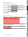
Process variables, output variables, and outputs . .
Configuring the milliamp outputs. . . . . . . . . . . . . . .
Frequency output . . . . . . . . . . . . . . . . . . . . . . . . . .
RFT9739 transmitters . . . . . . . . . . . . . . . . . . . . . . .
Series 1000 transmitters . . . . . . . . . . . . . . . . . . . . .
Series 2000 transmitters . . . . . . . . . . . . . . . . . . . . .
Series 1000 or 2000 frequency output scaling . . . .
RFT9739 frequency output scaling . . . . . . . . . . . . .
Reading milliamp output levels . . . . . . . . . . . . . . . .
Reading the frequency output . . . . . . . . . . . . . . . . .
Quaternary variable . . . . . . . . . . . . . . . . . . . . . . . .
100 Hz mode. . . . . . . . . . . . . . . . . . . . . . . . . . . . . .
67
68
70
78
78
78
78
79
81
84
85
86
86
Process Variables and Field Conditions. . . 89
10.1
10.2
10.3
10.4
10.5
10.6
10.7
Using Modbus® Protocol with Micro Motion® Transmitters
About this chapter . . . . . . . . . . . . . . . . . . . . . . . . . .
Low-flow cutoffs for mass flow and volume flow . . .
Mass, density, and volume interdependencies . . . .
Live zero flow . . . . . . . . . . . . . . . . . . . . . . . . . . . . .
Low-density cutoff . . . . . . . . . . . . . . . . . . . . . . . . . .
Mass, density, and volume interdependencies . . . .
Flow direction . . . . . . . . . . . . . . . . . . . . . . . . . . . . .
Digital damping . . . . . . . . . . . . . . . . . . . . . . . . . . . .
Slug flow limits . . . . . . . . . . . . . . . . . . . . . . . . . . . .
Slug duration . . . . . . . . . . . . . . . . . . . . . . . . . . . . . .
89
89
90
90
91
91
92
96
97
98
iii
Table of Contents continued
11
Process Controls. . . . . . . . . . . . . . . . . . . 101
11.1
11.2
11.4
11.5
11.6
11.7
12
About this chapter . . . . . . . . . . . . . . . . . . . . . . . . .
Real-time compensation . . . . . . . . . . . . . . . . . . . .
Compensation for stable operating pressures. . . .
Version 2 RFT9739 transmitters . . . . . . . . . . . . . .
Version 3 RFT9739 transmitters . . . . . . . . . . . . . .
129
130
133
134
137
Configuring the API Feature . . . . . . . . . . 141
14.1
14.2
14.3
14.4
iv
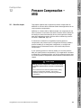
About this chapter . . . . . . . . . . . . . . . . . . . . . . . . . 125
Pressure compensation implementation
procedure
126
Pressure Compensation – RFT9739. . . . 129
13.1
13.2
13.3
14
101
102
103
103
104
108
108
108
109
109
109
109
111
111
112
112
116
120
120
120
120
123
124
Pressure Compensation – MVD . . . . . . . 125
12.1
12.2
13
About this chapter . . . . . . . . . . . . . . . . . . . . . . . . .
No outputs available . . . . . . . . . . . . . . . . . . . . . . .
Fault outputs . . . . . . . . . . . . . . . . . . . . . . . . . . . . .
Version 2 RFT9739 fault outputs. . . . . . . . . . . . . .
MVDSolo or Series 1000 or 2000 fault outputs . . .
Reading fault output levels . . . . . . . . . . . . . . . . . .
RFT9739 control output. . . . . . . . . . . . . . . . . . . . .
Flow direction . . . . . . . . . . . . . . . . . . . . . . . . . . . .
Zeroing in progress . . . . . . . . . . . . . . . . . . . . . . . .
Faults. . . . . . . . . . . . . . . . . . . . . . . . . . . . . . . . . . .
Event 1 and event 2. . . . . . . . . . . . . . . . . . . . . . . .
Series 2000 discrete output. . . . . . . . . . . . . . . . . .
Reading discrete output states . . . . . . . . . . . . . . .
Events . . . . . . . . . . . . . . . . . . . . . . . . . . . . . . . . . .
Event configuration procedure. . . . . . . . . . . . . . . .
Configuring RFT9739 events. . . . . . . . . . . . . . . . .
Configuring Series 1000 or 2000 event . . . . . . . . .
Reading event states. . . . . . . . . . . . . . . . . . . . . . .
Totalizers and inventories . . . . . . . . . . . . . . . . . . .
Totalizer functions . . . . . . . . . . . . . . . . . . . . . . . . .
Totalizer controls . . . . . . . . . . . . . . . . . . . . . . . . . .
Totalizer security . . . . . . . . . . . . . . . . . . . . . . . . . .
Resetting inventories . . . . . . . . . . . . . . . . . . . . . . .
About this chapter . . . . . . . . . . . . . . . . . . . . . . . . .
Definitions . . . . . . . . . . . . . . . . . . . . . . . . . . . . . . .
CTL derivation methods . . . . . . . . . . . . . . . . . . . .
Configuring API . . . . . . . . . . . . . . . . . . . . . . . . . . .
Using API. . . . . . . . . . . . . . . . . . . . . . . . . . . . . . . .
Reading API and CTL values from registers . . . . .
Assigning API and CTL values to outputs . . . . . . .
Displaying CTL values. . . . . . . . . . . . . . . . . . . . . .
VCF alarms . . . . . . . . . . . . . . . . . . . . . . . . . . . . . .
141
141
141
142
145
145
146
146
146
Using Modbus® Protocol with Micro Motion® Transmitters
Table of Contents continued
15
Configuring the Display – MVD . . . . . . . . 147
15.1
15.2
15.3
15.4
15.5
16
16.3
16.4
16.5
About this chapter . . . . . . . . . . . . . . . . . . . . . . . . .
Slot addresses and slot address sequences . . . .
Read commands . . . . . . . . . . . . . . . . . . . . . . . . . .
Configuring slot address sequences . . . . . . . . . . .
Reading slot address sequences . . . . . . . . . . . . .
Reading binary totals . . . . . . . . . . . . . . . . . . . . . .
Examples . . . . . . . . . . . . . . . . . . . . . . . . . . . . . . .
151
151
151
152
157
158
160
Characterization . . . . . . . . . . . . . . . . . . . . 163
17.1
17.2
17.3
17.4
17.5
18
147
147
148
148
148
149
150
Slot Addresses – MVD . . . . . . . . . . . . . . . 151
16.1
16.2
17
About this chapter . . . . . . . . . . . . . . . . . . . . . . . . .
Enabling and disabling display functions . . . . . . .
Operating menu . . . . . . . . . . . . . . . . . . . . . . . . . .
Scroll rate . . . . . . . . . . . . . . . . . . . . . . . . . . . . . . .
Display variables . . . . . . . . . . . . . . . . . . . . . . . . . .
Offline menu access . . . . . . . . . . . . . . . . . . . . . . .
Alarm menu access . . . . . . . . . . . . . . . . . . . . . . .
Overview . . . . . . . . . . . . . . . . . . . . . . . . . . . . . . . .
Flow calibration factor . . . . . . . . . . . . . . . . . . . . . .
Transmitter is pre-programmed . . . . . . . . . . . . . .
Transmitter is not pre-programmed . . . . . . . . . . .
Flow calibration factor format . . . . . . . . . . . . . . . .
Field flow calibration . . . . . . . . . . . . . . . . . . . . . . .
Density characterization . . . . . . . . . . . . . . . . . . . .
Transmitter is pre-programmed . . . . . . . . . . . . . .
Transmitter is not pre-programmed . . . . . . . . . . .
Density 1 and 2 . . . . . . . . . . . . . . . . . . . . . . . . . . .
Density calibration constants . . . . . . . . . . . . . . . .
Temperature coefficient for density. . . . . . . . . . . .
Temperature calibration factor . . . . . . . . . . . . . . .
Micro Motion T-Series factors . . . . . . . . . . . . . . . .
163
164
164
164
164
165
168
168
168
169
169
171
172
174
Calibration . . . . . . . . . . . . . . . . . . . . . . . . 175
18.1
18.2
18.3
18.4
Using Modbus® Protocol with Micro Motion® Transmitters
About this chapter . . . . . . . . . . . . . . . . . . . . . . . . .
Zeroing the flowmeter . . . . . . . . . . . . . . . . . . . . . .
Diagnosing zeroing failure . . . . . . . . . . . . . . . . . .
Flow signal offset . . . . . . . . . . . . . . . . . . . . . . . . .
Programming flowmeter zero time . . . . . . . . . . . .
Density calibration. . . . . . . . . . . . . . . . . . . . . . . . .
Density unit for calibration. . . . . . . . . . . . . . . . . . .
Calibration procedures . . . . . . . . . . . . . . . . . . . . .
Temperature calibration . . . . . . . . . . . . . . . . . . . .
Temperature unit for calibration . . . . . . . . . . . . . .
RFT9739 temperature calibration . . . . . . . . . . . . .
MVDSolo or Series 1000 or 2000 temperature
calibration . . . . . . . . . . . . . . . . . . . . . . . . . . . . .
175
176
177
178
179
181
181
182
192
192
192
195
v
Table of Contents continued
19
Meter Factors . . . . . . . . . . . . . . . . . . . . . 199
19.1
19.2
19.3
19.4
19.5
20
20.4
20.5
203
204
204
204
205
207
208
208
210
212
212
About this chapter . . . . . . . . . . . . . . . . . . . . . . . . . 213
Wiring for output trim . . . . . . . . . . . . . . . . . . . . . . . 214
Output trim procedure . . . . . . . . . . . . . . . . . . . . . . 214
Output and Transmitter Testing . . . . . . . 217
22.1
22.2
22.3
22.4
22.5
22.6
vi
About this chapter . . . . . . . . . . . . . . . . . . . . . . . . .
Saving non-volatile data . . . . . . . . . . . . . . . . . . . .
Security coils . . . . . . . . . . . . . . . . . . . . . . . . . . . . .
Defining security for all calibration factors . . . . . . .
Write-protecting selected registers . . . . . . . . . . . .
Write-protecting selected coils. . . . . . . . . . . . . . . .
Version 3 security event registers . . . . . . . . . . . . .
Configuration event register . . . . . . . . . . . . . . . . .
Calibration event register. . . . . . . . . . . . . . . . . . . .
Resetting security event registers . . . . . . . . . . . . .
Version 3 security breach . . . . . . . . . . . . . . . . . . .
Milliamp Output Trim . . . . . . . . . . . . . . . . 213
21.1
21.2
21.3
22
199
199
199
200
200
200
201
RFT9739 Security and Administration . . 203
20.1
20.2
20.3
21
About this chapter . . . . . . . . . . . . . . . . . . . . . . . . .
Default meter factors . . . . . . . . . . . . . . . . . . . . . . .
Meter factor options. . . . . . . . . . . . . . . . . . . . . . . .
Calculating the meter factor. . . . . . . . . . . . . . . . . .
Original calculation . . . . . . . . . . . . . . . . . . . . . . . .
Calculation after proving . . . . . . . . . . . . . . . . . . . .
Writing meter factors . . . . . . . . . . . . . . . . . . . . . . .
About this chapter . . . . . . . . . . . . . . . . . . . . . . . . .
Milliamp output test . . . . . . . . . . . . . . . . . . . . . . . .
Wiring for milliamp test . . . . . . . . . . . . . . . . . . . . .
Milliamp output test procedure –
RFT9739 transmitter . . . . . . . . . . . . . . . . . . . . .
Milliamp output test procedure –
Series 1000 or 2000 transmitter . . . . . . . . . . . .
Milliamp output test indicators . . . . . . . . . . . . . . . .
Frequency output test . . . . . . . . . . . . . . . . . . . . . .
Wiring for frequency output test. . . . . . . . . . . . . . .
Frequency output test procedure. . . . . . . . . . . . . .
Discrete output test . . . . . . . . . . . . . . . . . . . . . . . .
Discrete input test . . . . . . . . . . . . . . . . . . . . . . . . .
Transmitter test . . . . . . . . . . . . . . . . . . . . . . . . . . .
217
218
218
218
219
219
220
220
220
222
223
223
Using Modbus® Protocol with Micro Motion® Transmitters
Table of Contents continued
23
Troubleshooting . . . . . . . . . . . . . . . . . . . . 227
23.1
23.2
23.3
23.4
23.5
23.6
23.7
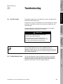
About this chapter . . . . . . . . . . . . . . . . . . . . . . . . .
Reading diagnostic codes . . . . . . . . . . . . . . . . . . .
Reading discrete inputs and input registers . . . . .
Reading register pairs . . . . . . . . . . . . . . . . . . . . . .
Transmitter diagnostic tools and reference . . . . . .
Diagnostic LED . . . . . . . . . . . . . . . . . . . . . . . . . . .
Test points . . . . . . . . . . . . . . . . . . . . . . . . . . . . . .
9-wire cable reference . . . . . . . . . . . . . . . . . . . . .
Sensor pickoff values reference . . . . . . . . . . . . . .
Nominal resistance values reference . . . . . . . . . .
Excessive drive gain procedures . . . . . . . . . . . . .
Faulty 9-wire sensor cabling procedures . . . . . . .
Sensor failure and overrange conditions . . . . . . .
Fault outputs . . . . . . . . . . . . . . . . . . . . . . . . . . . . .
Checking wiring. . . . . . . . . . . . . . . . . . . . . . . . . . .
Troubleshooting procedure . . . . . . . . . . . . . . . . . .
Output saturation and process out-of-range
conditions
Responding to diagnostic codes . . . . . . . . . . . . . .
Milliamp output performance. . . . . . . . . . . . . . . . .
Transmitter status bits. . . . . . . . . . . . . . . . . . . . . .
Transmitter not configured . . . . . . . . . . . . . . . . . .
Data loss possible . . . . . . . . . . . . . . . . . . . . . . . . .
Transmitter configuration changed . . . . . . . . . . . .
Power reset occurred . . . . . . . . . . . . . . . . . . . . . .
Transmitter initializing/warming up . . . . . . . . . . . .
Burst mode enabled . . . . . . . . . . . . . . . . . . . . . . .
RFT9739 display readback error (Version 3 only)
Customer service . . . . . . . . . . . . . . . . . . . . . . . . .
227
227
228
233
235
235
235
237
237
237
237
237
240
240
240
240
242
242
243
244
245
245
245
246
246
246
247
247
A
Modbus Mapping Assignments . . . . . . . . 249
B
Reference to Message Framing . . . . . . . . 279
B.1
B.2
B.3
B.4
B.5
Using Modbus® Protocol with Micro Motion® Transmitters
About this appendix . . . . . . . . . . . . . . . . . . . . . . .
Polling address . . . . . . . . . . . . . . . . . . . . . . . . . . .
Mapped addresses . . . . . . . . . . . . . . . . . . . . . . . .
Query messages and broadcast messages . . . . .
Broadcast mode and address 0 . . . . . . . . . . . . . .
Address field . . . . . . . . . . . . . . . . . . . . . . . . . . . . .
Function field. . . . . . . . . . . . . . . . . . . . . . . . . . . . .
Data field . . . . . . . . . . . . . . . . . . . . . . . . . . . . . . . .
Error check field . . . . . . . . . . . . . . . . . . . . . . . . . .
Data types . . . . . . . . . . . . . . . . . . . . . . . . . . . . . . .
Data addresses and number of points . . . . . . . . .
Coils and discrete inputs . . . . . . . . . . . . . . . . . . . .
Integer data . . . . . . . . . . . . . . . . . . . . . . . . . . . . . .
ASCII (string) data . . . . . . . . . . . . . . . . . . . . . . . .
Floating point data . . . . . . . . . . . . . . . . . . . . . . . .
279
279
279
280
280
281
281
285
286
286
287
287
288
289
289
vii
Table of Contents continued
B.6
B.7
C
Data transmission modes . . . . . . . . . . . . . . . . . . .
Message framing in ASCII mode. . . . . . . . . . . . . .
Message framing in RTU mode. . . . . . . . . . . . . . .
Error checking . . . . . . . . . . . . . . . . . . . . . . . . . . . .
Hardware determination of parity bits . . . . . . . . . .
Longitudinal redundancy check sequence
for ASCII mode . . . . . . . . . . . . . . . . . . . . . . . . .
Cyclic redundancy check for RTU mode . . . . . . . .
291
291
292
293
293
293
294
Configuration Record . . . . . . . . . . . . . . . 299
C.1
C.2
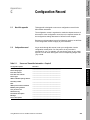
About this appendix . . . . . . . . . . . . . . . . . . . . . . . . 299
Configuration record . . . . . . . . . . . . . . . . . . . . . . . 299
Index . . . . . . . . . . . . . . . . . . . . . . . . . . . . . . . . 311
viii
Using Modbus® Protocol with Micro Motion® Transmitters
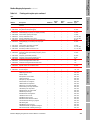
List of Tables
3
Implementing Modbus Protocol . . . . . . . . . 11
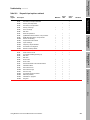
Table 3-1.
Table 3-2.
Table 3-3.
4
Using Modbus Commands . . . . . . . . . . . . . 21
Table 4-1.
5
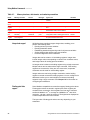
Memory structures, data formats, and
numbering conventions . . . . . . . . . . . . . . . . . . 22
Sensor and Transmitter Information . . . . . . 27
Table 5-1.
Table 5-2.
Table 5-3.
Table 5-4.
Table 5-5.
6
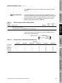
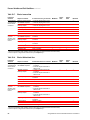
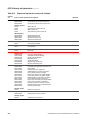
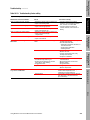
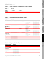
Series 1000 or 2000 digital communication
variable holding registers . . . . . . . . . . . . . . . . . 17
Additional delay to response holding register. . 19
Register values for additional response
time delay . . . . . . . . . . . . . . . . . . . . . . . . . . . . . 19
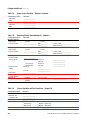
Sensor serial number register pair . . . . . . . . . .
Sensor information holding registers . . . . . . . .
Configurable transmitter information –
integer values . . . . . . . . . . . . . . . . . . . . . . . . . .
Configurable transmitter information –
character strings . . . . . . . . . . . . . . . . . . . . . . . .
Non-configurable transmitter information . . . . .
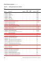
Outputs, Option Boards, and
Communications
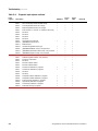
Table 6-1.
Table 6-2.
Table 6-3.
Table 6-4.
Table 6-5.
Table 6-6.
Table 6-7.
Table 6-8.
Table 6-9.
Table 6-10.
Table 6-11.
Table 6-12.
Table 6-13.
Using Modbus® Protocol with Micro Motion® Transmitters
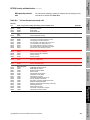
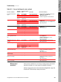
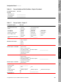
Transmitters, option boards, and outputs . . . . .
Series 2000 configurable input/output
board channel configuration . . . . . . . . . . . . . . .
Series 2000 configurable input/output
board power source configuration . . . . . . . . . .
Series 2000 configurable input/output
board discrete output voltages . . . . . . . . . . . . .
Series 2000 configurable input/output
board frequency output mode configuration . . .
Discrete input assignment codes . . . . . . . . . . .
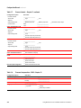
Series 2000 frequency output polarity
configuration . . . . . . . . . . . . . . . . . . . . . . . . . . .
Series 2000 discrete output configuration . . . .
Transmitter polling via HART protocol . . . . . . .
Transmitter polling via Modbus protocol. . . . . .
HART burst mode control coil. . . . . . . . . . . . . .
HART burst mode process data . . . . . . . . . . . .
HART burst mode code 33 process variables .
28
28
30
31
32
33
34
35
35
36
36
36
37
37
38
39
39
39
40
ix
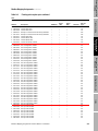
List of Tables continued
Table 6-14.
Table 6-15.
Table 6-16.
Table 6-17.
External HART device polling tag . . . . . . . . . . .
Polling control type – Series 1000 and 2000 . .
Polled data – Series 1000 and 2000 . . . . . . . . .
Polling type – Series 1000 and 2000,
Version 2 and earlier . . . . . . . . . . . . . . . . . . . . .
Table 6-18. Polling control type – RFT9739. . . . . . . . . . . . .
Table 6-19. Fieldbus simulation mode control coil . . . . . . . .
Table 6-20. Profibus-PA station address . . . . . . . . . . . . . . .
7
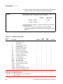
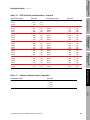
Mass flow units . . . . . . . . . . . . . . . . . . . . . . . . .
Mass total and mass inventory units . . . . . . . . .
Volume flow units . . . . . . . . . . . . . . . . . . . . . . .
Volume total and volume inventory units . . . . .
Base mass and volume units for
special mass or special volume units . . . . . . . .
Table 7-6.
Special mass or special volume unit
conversion factors . . . . . . . . . . . . . . . . . . . . . . .
Table 7-7.
Time units for special mass or special
volume units . . . . . . . . . . . . . . . . . . . . . . . . . . .
Table 7-8.
MVDSolo or Series 1000 or 2000
special unit character strings . . . . . . . . . . . . . .
Table 7-9.
RFT9739 special unit character strings . . . . . .
Table 7-10. Density units . . . . . . . . . . . . . . . . . . . . . . . . . . .
Table 7-11. Temperature units . . . . . . . . . . . . . . . . . . . . . . .
Table 7-12. Pressure units . . . . . . . . . . . . . . . . . . . . . . . . . .
50
50
50
51
51
53
54
54
Process variable registers. . . . . . . . . . . . . . . . .
Measurement unit holding registers . . . . . . . . .
RFT9739 binary total input registers . . . . . . . . .
Maximum integer holding register . . . . . . . . . . .
Scale factor holding registers . . . . . . . . . . . . . .
Offset holding registers . . . . . . . . . . . . . . . . . . .
56
56
57
60
61
62
Reporting Process Data with Outputs . . . . 67
Table 9-1.
Table 9-2.
Table 9-3.
Table 9-4.
Table 9-5.
Process variable registers. . . . . . . . . . . . . . . . .
Output variable assignment registers . . . . . . . .
Output present level registers . . . . . . . . . . . . . .
RFT9739 milliamp output holding registers . . .
Series 1000 or 2000 milliamp output
holding register . . . . . . . . . . . . . . . . . . . . . . . . .
Table 9-6.
Sensor limit read-only register pairs . . . . . . . . .
Table 9-7.
Milliamp output URV and LRV register pairs . .
Table 9-8.
Milliamp output low-flow cutoff register pairs . .
Table 9-9.
RFT9739 milliamp output added damping
register pairs . . . . . . . . . . . . . . . . . . . . . . . . . . .
Table 9-10. Series 1000 or 2000 milliamp output
added damping register pairs . . . . . . . . . . . . . .
x
46
47
47
48
Using Process Variables . . . . . . . . . . . . . . 55
Table 8-1.
Table 8-2.
Table 8-3.
Table 8-4.
Table 8-5.
Table 8-6.
9
42
42
42
43
Measurement Units for Process Variables 45
Table 7-1.
Table 7-2.
Table 7-3.
Table 7-4.
Table 7-5.
8
41
41
41
69
69
70
71
71
72
73
74
76
77
Using Modbus® Protocol with Micro Motion® Transmitters
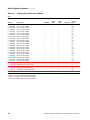
List of Tables continued
Table 9-11. RFT9739 frequency output variable
holding register . . . . . . . . . . . . . . . . . . . . . . . . .
Table 9-12. Series 2000 frequency output variable
holding register . . . . . . . . . . . . . . . . . . . . . . . . .
Table 9-13. Scaling method holding register . . . . . . . . . . . .
Table 9-14. Frequency=flow rate register pairs . . . . . . . . . .
Table 9-15. Pulses/unit register pair . . . . . . . . . . . . . . . . . .
Table 9-16. Units/pulse register pair . . . . . . . . . . . . . . . . . .
Table 9-17. Frequency and flow rate register pairs . . . . . . .
Table 9-18. Pulse width register pair . . . . . . . . . . . . . . . . . .
Table 9-19. Present current level register pair. . . . . . . . . . .
Table 9-20. Present output frequency register pair . . . . . . .
Table 9-21. Quaternary variable holding register . . . . . . . .
Table 9-22. 100 Hz mode process variables
holding register . . . . . . . . . . . . . . . . . . . . . . . . .
Table 9-23. Update rate holding register . . . . . . . . . . . . . . .
10
79
79
80
80
81
82
83
84
86
87
87
88
Process Variables and Field Conditions. . . 89
Table 10-1.
Table 10-2.
Table 10-3.
Table 10-4.
Table 10-5.
Table 10-6.
Table 10-7.
Table 10-8.
Table 10-9.
Table 10-10.
Table 10-11.
Table 10-12.
Table 10-13.
Low-flow cutoff register pairs . . . . . . . . . . . . . .
Live zero flow registers. . . . . . . . . . . . . . . . . . .
Low-density cutoff register pair. . . . . . . . . . . . .
Flow direction holding register . . . . . . . . . . . . .
Flow direction status bit . . . . . . . . . . . . . . . . . .
Effect of forward flow . . . . . . . . . . . . . . . . . . . .
Effect of reverse flow . . . . . . . . . . . . . . . . . . . .
Effect of bidirectional flow. . . . . . . . . . . . . . . . .
Effect of absolute forward/reverse flow . . . . . .
Effect of negate – forward flow . . . . . . . . . . . . .
Effect of negate – bidirectional flow . . . . . . . . .
RFT9739 digital damping register pairs . . . . . .
MVDSolo or Series 1000 or 2000 digital
damping register pairs . . . . . . . . . . . . . . . . . . .
Table 10-14. Slug flow status bits . . . . . . . . . . . . . . . . . . . . .
Table 10-15. Slug flow register pairs . . . . . . . . . . . . . . . . . . .
Table 10-16. Slug duration register pair . . . . . . . . . . . . . . . .
11
78
90
91
91
92
93
93
94
94
95
95
95
97
97
98
98
99
Process Controls . . . . . . . . . . . . . . . . . . . 101
Table 11-1. RFT9739 system conditions and indicators . .
Table 11-2. MVDSolo or Series 1000 and Series 2000
system conditions and outputs . . . . . . . . . . . .
Table 11-3. Version 2 RFT9739 fault output
holding register . . . . . . . . . . . . . . . . . . . . . . . .
Table 11-4. Series 1000 or 2000 fault output
holding registers . . . . . . . . . . . . . . . . . . . . . . .
Table 11-5. Series 1000 or 2000 fault levels
register pairs. . . . . . . . . . . . . . . . . . . . . . . . . .
Table 11-6. RS-485 digital output holding register . . . . . .
Table 11-7. Last measured value fault timeout
holding register . . . . . . . . . . . . . . . . . . . . . . . .
Table 11-8. Output levels register pairs. . . . . . . . . . . . . . .
Using Modbus® Protocol with Micro Motion® Transmitters
102
102
104
106
106
107
108
108
xi
List of Tables continued
Table 11-9. RFT9739 control output holding register. . . . .
Table 11-10. Discrete output assignment holding register . .
Table 11-11. Discrete output flow switch setpoint
register pair . . . . . . . . . . . . . . . . . . . . . . . . . . .
Table 11-12. Discrete output indicator status bits . . . . . . . .
Table 11-13. RFT9739 event process variable
holding register . . . . . . . . . . . . . . . . . . . . . . . .
Table 11-14. RFT9739 event alarm-type holding register . .
Table 11-15. RFT9739 event setpoint register pairs . . . . . .
Table 11-16. RFT9739 event assignment holding register .
Table 11-17. RFT9739 event current-level register pairs. . .
Table 11-18. Series 1000 or 2000 event process variable
holding registers . . . . . . . . . . . . . . . . . . . . . . .
Table 11-19. Series 1000 or 2000 event alarm-type
holding registers . . . . . . . . . . . . . . . . . . . . . . .
Table 11-20. Series 1000 or 2000 event setpoint
register pairs . . . . . . . . . . . . . . . . . . . . . . . . . .
Table 11-21. Event state status bits . . . . . . . . . . . . . . . . . . .
Table 11-22. Totalizer control coils . . . . . . . . . . . . . . . . . . .
Table 11-23. Mass or volume total input registers . . . . . . . .
Table 11-24. Series 1000 or 2000 totalizer display coil . . . .
Table 11-25. Disabling RFT9739 totalizer controls . . . . . . .
Table 11-26. Mass or volume inventory input registers . . . .
12
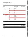
Pressure compensation coil . . . . . . . . . . . . . .
Pressure correction register pairs . . . . . . . . . .
Flow calibration pressure register pair . . . . . .
Gauge pressure register pair . . . . . . . . . . . . .
117
118
119
120
121
122
123
123
124
126
127
127
128
130
131
132
133
133
135
137
138
140
Configuring the API Feature . . . . . . . . . . 141
Table 14-1. API reference temperature tables . . . . . . . . . .
Table 14-2. API reference temperature table
holding register . . . . . . . . . . . . . . . . . . . . . . . .
Table 14-3. Temperature units . . . . . . . . . . . . . . . . . . . . . .
Table 14-4. API reference temperature table register pair .
xii
112
113
114
115
116
Pressure Compensation – RFT9739. . . . 129
Table 13-1. RFT9739 Version 3 pressure data
receiving method holding register . . . . . . . . . .
Table 13-2. Pressure correction register pairs . . . . . . . . . .
Table 13-3. RFT9739 gauge pressure registers . . . . . . . .
Table 13-4. Pressure input register pairs . . . . . . . . . . . . . .
Table 13-5. Flow calibration pressure register pair . . . . . .
Table 13-6. Flow calibration factor character strings . . . . .
Table 13-7. K2 register pair . . . . . . . . . . . . . . . . . . . . . . . .
Table 13-8. Mass flow meter factor register pair . . . . . . . .
Table 13-9. Density meter factor register pair . . . . . . . . . .
14
110
111
Pressure Compensation – MVD . . . . . . . 125
Table 12-1.
Table 12-2.
Table 12-3.
Table 12-4.
13
109
110
142
143
143
143
Using Modbus® Protocol with Micro Motion® Transmitters
List of Tables continued
Table 14-5. API thermal expansion coefficient
register pair. . . . . . . . . . . . . . . . . . . . . . . . . . .
Table 14-6. Fixed temperature register pair . . . . . . . . . . .
Table 14-7. Enable/disable non-sensor temperature. . . . .
Table 14-8. Enable/disable CTL calculation . . . . . . . . . . .
Table 14-9. CTL data in registers . . . . . . . . . . . . . . . . . . .
Table 14-10. VCF alarm bits . . . . . . . . . . . . . . . . . . . . . . . .
15
Configuring the Display – MVD . . . . . . . . 147
Table 15-1.
Table 15-2.
Table 15-3.
Table 15-4.
16
Display function coils . . . . . . . . . . . . . . . . . . .
Scroll rate holding register . . . . . . . . . . . . . . .
Display variable holding registers. . . . . . . . . .
Offline menu password holding register . . . . .
153
155
156
157
158
Characterization . . . . . . . . . . . . . . . . . . . . 163
Table 17-1. Mass flow meter factor register pair . . . . . . . .
Table 17-2. Mass and volume total registers. . . . . . . . . . .
Table 17-3. Flow calibration factor values –
ASCII format . . . . . . . . . . . . . . . . . . . . . . . . . .
Table 17-4. Flow calibration factor values –
floating-point format . . . . . . . . . . . . . . . . . . . .
Table 17-5. Methods for writing density factors . . . . . . . . .
Table 17-6. Density 1 and 2 register pairs. . . . . . . . . . . . .
Table 17-7. Density constant register pairs . . . . . . . . . . . .
Table 17-8. Density temperature coefficient register pair .
Table 17-9. Temperature calibration factor –
ASCII format . . . . . . . . . . . . . . . . . . . . . . . . . .
Table 17-10. Temperature calibration factor –
floating-point format . . . . . . . . . . . . . . . . . . . .
Table 17-11. Micro Motion T-Series characterization
register pairs. . . . . . . . . . . . . . . . . . . . . . . . . .
18
147
148
149
149
Slot Addresses – MVD . . . . . . . . . . . . . . . 151
Table 16-1. Slot address sequence holding registers –
mapped addresses . . . . . . . . . . . . . . . . . . . . .
Table 16-2. Slot address sequences – integer codes
for process variables . . . . . . . . . . . . . . . . . . .
Table 16-3. Slot address sequence holding registers –
process variables . . . . . . . . . . . . . . . . . . . . . .
Table 16-4. Slot address sequences – register pairs
for mapped addresses . . . . . . . . . . . . . . . . . .
Table 16-5. Slot address sequences – register pairs
for process variables . . . . . . . . . . . . . . . . . . .
17
144
144
144
145
145
146
165
166
167
167
169
170
171
172
173
173
174
Calibration . . . . . . . . . . . . . . . . . . . . . . . . 175
Table 18-1. Zeroing in progress status bits . . . . . . . . . . . . 177
Table 18-2. Zeroing failure status bits . . . . . . . . . . . . . . . . 178
Using Modbus® Protocol with Micro Motion® Transmitters
xiii
List of Tables continued
Table 18-3.
Table 18-4.
Table 18-5.
Table 18-6.
Table 18-7.
Table 18-8.
Table 18-9.
Table 18-10.
Table 18-11.
Table 18-12.
Table 18-13.
Table 18-14.
Table 18-15.
Table 18-16.
Table 18-17.
Table 18-18.
Table 18-19.
Table 18-20.
Table 18-21.
Table 18-22.
Table 18-23.
Table 18-24.
Table 18-25.
Table 18-26.
Table 18-27.
Table 18-28.
19
Zeroing failure source status bits . . . . . . . . . .
Flow signal offset register pair . . . . . . . . . . . .
Flowmeter zeroing standard deviation limit. . .
Flowmeter zeroing standard deviation
register pairs . . . . . . . . . . . . . . . . . . . . . . . . . .
Flowmeter zero time holding register . . . . . . .
Flow rates requiring flowing density
calibration . . . . . . . . . . . . . . . . . . . . . . . . . . . .
Density of air . . . . . . . . . . . . . . . . . . . . . . . . . .
Low-density calibration addresses . . . . . . . . .
Low-density calibration status bits . . . . . . . . .
Maximum low-flow rates for high-density
calibration . . . . . . . . . . . . . . . . . . . . . . . . . . . .
Density of water . . . . . . . . . . . . . . . . . . . . . . .
High-density calibration addresses . . . . . . . . .
High-density calibration status bits . . . . . . . . .
Read-only density registers . . . . . . . . . . . . . .
Flowing-density calibration addresses . . . . . .
Flowing density calibration status bit . . . . . . .
D3 density calibration addresses . . . . . . . . . .
D3 density calibration status bits . . . . . . . . . .
D4 density calibration addresses . . . . . . . . . .
D4 density calibration status bits . . . . . . . . . .
Read-only temperature registers . . . . . . . . . .
Temperature calibration character string . . . .
Temperature offset calibration addresses. . . .
Temperature offset calibration status bits . . . .
Temperature slope calibration addresses . . . .
Temperature slope calibration status bits . . . .
178
178
179
180
180
182
183
183
184
184
186
186
187
188
188
189
190
190
191
191
193
194
195
196
196
197
Meter Factors . . . . . . . . . . . . . . . . . . . . . 199
Table 19-1. Meter factor register pairs . . . . . . . . . . . . . . . . 201
20
RFT9739 Security and Administration . . 203
Table 20-1.
Table 20-2.
Table 20-3.
Table 20-4.
Table 20-5.
Table 20-6.
Table 20-7.
Table 20-8.
Table 20-9.
Table 20-10.
xiv
Coil for saving non-volatile data . . . . . . . . . . .
Calibration factor security coils . . . . . . . . . . . .
Register and register pair security coils . . . . .
Coil and discrete input security coils . . . . . . . .
Configuration event holding register,
Versions 3.0 to 3.5 . . . . . . . . . . . . . . . . . . . . .
Configuration event holding register,
Versions 3.6 and higher . . . . . . . . . . . . . . . . .
Calibration event holding register,
Versions 3.0 to 3.5 . . . . . . . . . . . . . . . . . . . . .
Calibration event holding register,
Versions 3.6 and higher . . . . . . . . . . . . . . . . .
Security event register reset coil . . . . . . . . . . .
Security breach input register . . . . . . . . . . . . .
204
204
205
207
208
209
210
211
212
212
Using Modbus® Protocol with Micro Motion® Transmitters
List of Tables continued
21
Milliamp Output Trim . . . . . . . . . . . . . . . . 213
Table 21-1. Milliamp output terminals . . . . . . . . . . . . . . . . 214
Table 21-2. Milliamp output trim addresses. . . . . . . . . . . . 215
Table 21-3. Milliamp output trim status bits . . . . . . . . . . . . 216
22
Output and Transmitter Testing . . . . . . . . 217
Table 22-1. Milliamp output terminals . . . . . . . . . . . . . . . .
Table 22-2. Milliamp output test addresses –
RFT9739 transmitter. . . . . . . . . . . . . . . . . . . .
Table 22-3. Milliamp output test addresses –
Series 1000 or 2000 transmitter . . . . . . . . . . .
Table 22-4. Milliamp output test status bits . . . . . . . . . . . .
Table 22-5. Frequency output terminals . . . . . . . . . . . . . .
Table 22-6. Frequency output test addresses . . . . . . . . . .
Table 22-7. Frequency output test status bit . . . . . . . . . . .
Table 22-8. Discrete output state code holding registers .
Table 22-9. Discrete output forcing coils . . . . . . . . . . . . . .
Table 22-10. Discrete output state code input registers . . .
Table 22-11. Series 2000 discrete input state codes. . . . . .
Table 22-12. Transmitter test coil . . . . . . . . . . . . . . . . . . . .
Table 22-13. RFT9739 failure status bits. . . . . . . . . . . . . . .
Table 22-14. MVDSolo or Series 1000 or 2000 failure
status bits . . . . . . . . . . . . . . . . . . . . . . . . . . . .
23
218
219
220
220
221
221
222
222
223
223
224
224
225
Troubleshooting . . . . . . . . . . . . . . . . . . . . 227
Table 23-1.
Table 23-2.
Table 23-3.
Table 23-4.
Table 23-5.
Table 23-6.
Table 23-7.
Table 23-8.
Table 23-9.
Table 23-10.
Table 23-11.
Table 23-12.
Table 23-13.
Table 23-14.
Table 23-15.
Table 23-16.
Table 23-17.
Table 23-18.
A
218
Diagnostic discrete inputs. . . . . . . . . . . . . . . .
Diagnostic input registers . . . . . . . . . . . . . . . .
Diagnostic register pairs . . . . . . . . . . . . . . . . .
Operating conditions indicated by LED . . . . .
Test point register pairs . . . . . . . . . . . . . . . . .
9-wire cable terminal and wire designations. .
Sensor pickoff values . . . . . . . . . . . . . . . . . . .
Nominal resistance values for flowmeter
circuits . . . . . . . . . . . . . . . . . . . . . . . . . . . . . .
Troubleshooting excessive drive gain . . . . . .
Troubleshooting 9-wire cabling. . . . . . . . . . . .
Process limit diagnostic codes . . . . . . . . . . . .
Transmitter not configured status bits . . . . . .
Data loss possible status bits . . . . . . . . . . . . .
Transmitter configuration changed status bit .
Power reset status bits . . . . . . . . . . . . . . . . . .
Transmitter warming up status bits. . . . . . . . .
Burst mode enabled status bits . . . . . . . . . . .
Display readback error status bit . . . . . . . . . .
228
229
234
236
236
237
237
238
238
239
242
245
245
245
246
246
246
247
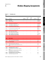
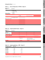
Modbus Mapping Assignments . . . . . . . . 249
Table A-1.
Table A-2.
Using Modbus® Protocol with Micro Motion® Transmitters
Read/write coils . . . . . . . . . . . . . . . . . . . . . . . 249
RFT9739 security coils . . . . . . . . . . . . . . . . . . 250
xv
List of Tables continued
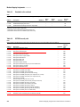
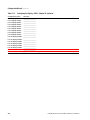
Table A-3.
Table A-4.
Table A-5.
Table A-6.
Table A-7.
Table A-8.
B
251
252
257
262
266
268
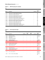
Reference to Message Framing . . . . . . . 279
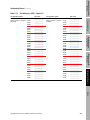
Table B-1.
Table B-2.
Table B-3.
Table B-4.
Table B-5.
Table B-6.
Table B-7.
Table B-8.
Table B-9.
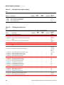
Table B-10.
Table B-11.
Table B-12.
Table B-13.
xvi
Read-only discrete inputs . . . . . . . . . . . . . . . .
Floating-point register pairs . . . . . . . . . . . . . .
Input registers . . . . . . . . . . . . . . . . . . . . . . . . .
Holding registers . . . . . . . . . . . . . . . . . . . . . . .
ASCII character strings . . . . . . . . . . . . . . . . . .
Integer codes . . . . . . . . . . . . . . . . . . . . . . . . .
Data transmission fields . . . . . . . . . . . . . . . . .
Modbus function codes . . . . . . . . . . . . . . . . . .
Explanation of function codes supported by
Micro Motion® transmitters . . . . . . . . . . . . . . .
Modbus® exception responses . . . . . . . . . . . .
Exception responses supported by
Micro Motion® transmitters . . . . . . . . . . . . . . .
Data types according to function code and
mapped address . . . . . . . . . . . . . . . . . . . . . . .
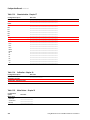
Data transmission order for start address
and number of query . . . . . . . . . . . . . . . . . . . .
Data transmission order for integer data. . . . .
Floating point byte ordering holding register . .
Comparison of ASCII and RTU data
transmission modes . . . . . . . . . . . . . . . . . . . .
ASCII message frame format . . . . . . . . . . . . .
RTU message frame format . . . . . . . . . . . . . .
Example CRC (read exception status
from slave 02) . . . . . . . . . . . . . . . . . . . . . . . . .
280
281
282
286
286
287
287
288
290
291
292
292
296
Using Modbus® Protocol with Micro Motion® Transmitters
Before You Begin
Introduction
1
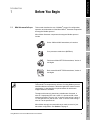
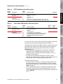
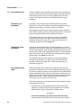
What this manual tells you
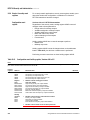
This manual describes the use of Modbus® protocol for configuration,
operation, and maintenance of the Micro Motion® flowmeter components
that support Modbus protocol.
Implementting
Modbus Protocol
Micro Motion flowmeter components that support Modbus protocol
include:
Introduction to
Modbus Protocol
1.1
Before You Begin
Series 1000 and 2000 transmitters, all versions
Core processor stand-alone (MVDSolo)
Using Modbus
Commands
Field-mount Model RFT9739 transmitters, Version 2
and higher
Sensor and Transmitter
Information
Rack-mount Model RFT9739 transmitters, Version 2
and higher
Outputs, Option Boards,
and Communications
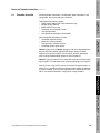
Keys to using this manual
This manual is a comprehensive reference for using Modbus protocol
with Micro Motion transmitters. Tables throughout this manual contain
checkmarks (Ö) that identify the implementations for which each
mapped address is available.
Throughout this manual, when binary variables are discussed, a
value of 0 represents OFF and a value of 1 represents ON, unless
otherwise specified. The term “set” is used to mean writing a value of
1 to the specified coil, and the term “reset” is used to mean writing a
value of 0 to the specified coil.
Using Modbus® Protocol with Micro Motion® Transmitters
1
Measurement Units
Micro Motion strongly recommends that you make a record of your
transmitter configuration. See Section 1.4, page 5.
Before You Begin continued
1.2
Organization of this
manual
This manual is organized into three major sections:
• Introduction
• Configuration
• Maintenance
Each section contains several chapters. The section name is displayed
on the first page of each chapter, above the chapter number.
1.3
How to use this manual
This manual focuses on using Modbus protocol for transmitter
configuration, operation, and maintenance. It is not designed as a
operations or reference manual for either the sensor or the transmitter.
For more detailed information on these components, refer to the
manuals supplied with the transmitter or sensor.
This manual describes how to perform setup, configuration, calibration,
and troubleshooting procedures using the Modbus protocol. Some
procedures are required; others are optional.
Information on using the Modbus protocol is provided in Chapter 4 and
Appendix B.
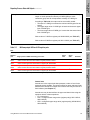
Required procedures
In all cases, you must:
• Enable Modbus protocol (see Chapter 3)
• Zero the flowmeter (see Chapter 18)
Flowmeter zero establishes flowmeter response to zero flow and sets a
baseline for flow measurement.
CAUTION
Failure to zero the flowmeter at initial startup could
cause the flowmeter to produce inaccurate signals.
Zero the flowmeter before putting it into operation. To zero
the flowmeter, see Chapter 18.
If your flowmeter is on a multidrop network, you must configure its
polling address (see Chapter 5).
Other procedures
Review Chapter 6 for configuration information related to your
transmitter, option board, and network.
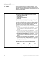
Characterization may or may not be required:
• When a complete flowmeter (transmitter and sensor combination) is
ordered, the individual units are characterized for each other at the
factory. You may customize the configuration as desired or required
by your application.
• If the components are ordered separately, or one component is
replaced in the field, the units are not characterized for each other.
2
Using Modbus® Protocol with Micro Motion® Transmitters
Before You Begin
Before You Begin continued
These procedures must be performed. You can then customize the
configuration as described above.
Introduction to
Modbus Protocol
Additionally, field calibration and related procedures may be required if:
• The application is highly sensitive to density or temperature
• Transmitter outputs must be matched to a specific reference
standard, receiver, or readout device
Finally, a master reset sets all values in transmitter memory to precharacterization factory defaults. Complete reconfiguration of the
transmitter is required after a master reset.
Implementting
Modbus Protocol
CAUTION
Contact Micro Motion customer support before
performing a master reset.
Perform a master reset only after all other options have
been explored.
Characterization
Using Modbus
Commands
Characterization is the process of writing sensor-specific information to
the transmitter, for example:
• The flow calibration factor describes a particular sensor’s sensitivity
to flow.
• Density factors describe a particular sensor’s sensitivity to density.
• The temperature calibration factor describes the slope and offset of
the equation used for calculating temperature.
Characterization procedures are described in Chapter 17.
Calibration
Outputs, Option Boards,
and Communications
Calibration accounts for performance variations in individual sensors,
transmitters, and peripheral devices, for example:
• Flowmeter zeroing establishes flowmeter response to zero flow and
sets a baseline for flow measurement.
• Density calibration adjusts factors used by the transmitter in
calculating density.
• Temperature calibration adjusts factors used by the transmitter in
calculating temperature. Temperature calibration is not
recommended.
Field calibration overwrites some or all of the values written during
characterization. Calibration procedures are described in Chapter 18
through Chapter 21.
3
Measurement Units
Using Modbus® Protocol with Micro Motion® Transmitters
Sensor and Transmitter
Information
If the transmitter is not characterized for the sensor in use, measurement
error will result.
Before You Begin continued
Customizing the
configuration
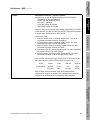
To customize the flowmeter for your application, use the following
general procedure.
1. Configure your transmitter with basic information about the sensor
(see Chapter 5).
2. Configure your transmitter’s option boards, outputs, and
communications (see Chapter 6).
3. Determine what process variable or variables you will measure. A
process variable is any of the variables that can be measured by the
sensor. The following process variables may be measured (not all
flowmeters measure all process variables):
• Mass flow rate
• Mass total
• Mass inventory
• Volume flow rate
• Volume total
• Volume inventory
• Density
• Temperature
• Pressure
Mass total and volume total are used for “batches.” These process
variables can be reset to 0. Mass inventory and volume inventory
track values over time, across batches, and are typically never reset.
4. Determine what measurement units will be used for the selected
process variables. Configure the flowmeter to use these
measurement units. (See Chapter 7 and Chapter 8.)
5. Decide how you will read process variable data. You can read the
values dynamically from the transmitter registers or you can map
them to outputs. You can use both methods, unless you are using
MVDSolo, which does not provide outputs.
If a process variable is mapped to an output, the data are automatically sent to an external device such as a host controller.
6. Adjust the process variable measurements for various field
conditions (see Chapter 10).
7. If you will use outputs to report process data:
• Decide which process variable will be mapped to which output.
• Perform the mapping (see Chapter 9).
8. Perform additional output configuration (see Chapter 11). Typical
configuration includes:
• Defining fault indicators
• Defining process controls
9. Review the remainder of this manual and follow instructions for any
features that are relevant to your application.
4
Using Modbus® Protocol with Micro Motion® Transmitters
Before You Begin
Before You Begin continued
1.4
Recording transmitter
configuration
After completing transmitter configuration, you should record the
configuration.
If you do not have ProLink, use the configuration record provided in
Appendix C.
1.5
This manual does not explain transmitter installation or wiring. For
information about installation and wiring, see the transmitter and sensor
installation manuals. To order manuals, see below.
For customer service, or to order manuals:
• Inside the U.S.A., phone 1-800-522-6277, 24 hours
• In South America, Central America, and North America outside the
U.S.A., phone 303-530-8400, 24 hours
• In Europe, phone +31 (0) 318 549 443
• In Asia, phone 65-770-8155
• Visit us on the Internet at http://www.micromotion.com
Using Modbus
Commands
Customer service
This manual does not explain terminology and procedures for using
Modbus protocol, or how to use a host controller to communicate with
other devices in a Modbus-compatible multidrop network. For detailed
information about using Modbus protocol, visit http://www.modicon.com.
Implementting
Modbus Protocol
1.6
What this manual does not
tell you
Introduction to
Modbus Protocol
If you are using Micro Motion® ProLink II™ Version 1.1 or higher, you can
download the transmitter configuration to your computer system. See
the ProLink documentation for instructions.
Sensor and Transmitter
Information
Outputs, Option Boards,
and Communications
5
Measurement Units
Using Modbus® Protocol with Micro Motion® Transmitters
6
Using Modbus® Protocol with Micro Motion® Transmitters
Before You Begin
Introduction
2
Introduction to Modbus Protocol
with Micro Motion Transmitters
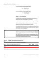
This chapter provides an introduction to using Modbus protocol with
Micro Motion transmitters.
2.2
Introduction to Micro
Motion transmitters
The Micro Motion transmitter is designed to provide fluid process
measurement and control. The transmitter works with a Micro Motion
sensor to measure mass flow, fluid density, and temperature.
The transmitter emulates a Modbus programmable logic controller (PLC)
in an RS-485 multidrop network. The transmitter supports 7-bit
American Standard Code for Information Interchange (ASCII) or 8-bit
Remote Terminal Unit (RTU) data transmission mode with a subset of
read commands, write commands, and diagnostic commands used by
most Modbus host controllers.
The core processor is not a transmitter per se. The core processor
component stores configuration information, receives signal inputs from
the sensor, and processes these inputs to yield process data. The
process data are available in core processor memory, for direct access
from a host controller.
In addition, all Series 1000 and 2000 transmitter implementations
include the core processor. The transmitter adds output functionality to
the basic core processor functionality. The Series 1000 or 2000
transmitter may also supply a display. No display is provided with
MVDSolo.
Using Modbus® Protocol with Micro Motion® Transmitters
7
Measurement Units
MVDSolo functions are identical to Series 1000 and 2000 functions
except for display and output functions.
Outputs, Option Boards,
and Communications
The core processor can be used without a transmitter. In this case, the
core processor communicates directly with an external host. This
implementation is called “MVDSolo” if no barrier is installed between the
core processor and the external host, or “MVD Direct Connect” if a
barrier is installed.
Sensor and Transmitter
Information
MVDSolo vs. Series 1000
or 2000 transmitter
Using Modbus
Commands
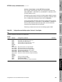
This manual addresses the use of Modbus protocol with the following
transmitter types:
• MVDSolo (core processor stand-alone)
• Series 1000
• Series 2000
• RFT9739
Implementting
Modbus Protocol
About this chapter
Introduction to
Modbus Protocol
2.1
Introduction to Modbus Protocol with Micro Motion Transmitters continued
Note: The term “MVD® ”means “Multi Variable Digital.” It refers to the
type of processing that is performed in the core processor and Series
1000 or 2000 transmitters. In this manual, MVD is used to refer to the
flowmeter implementations that use MVD processing.
Keys to using this manual
• Unless otherwise specified, the term “transmitter” includes the
MVDSolo implementation.
• Unless otherwise specified, all references to MVDSolo also apply
to MVD Direct Connect.
• References to MVD indicate the Series 1000 and 2000
transmitters and MVDSolo, or the Series 1000 and 2000
transmitters omitting MVDSolo.
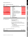
Mapped address types
The transmitter emulates Modbus read/write and read-only coils and
registers, including all the following types of mapped addresses:
• Read/write ON/OFF memory locations known as “coils”
• Read-only ON/OFF memory locations known as “discrete inputs”
• Read-only 16-bit input registers
• Read/write 16-bit holding registers
• Registers that store pairs of 8-bit ASCII characters
• Register pairs that store 32-bit floating-point values in single
precision IEEE 754 format
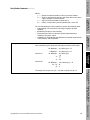
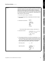
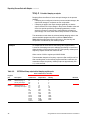
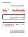
The mapped 5-digit addresses store and use data types supported by
many Modbus PLCs. Table B-6, page 287, lists data types according to
their mapped addresses and corresponding function codes.
Using some PLCs, you must subtract 1 from the address or starting
address.
• When you send a Modbus message that specifies a register, subtract
1 from the address.
• When you send a Modbus message that specifies a series of
consecutive registers, subtract 1 from the starting address.
Example
Refer to your PLC documentation to know if this applies to you. If it
does:
This Modbus manual specifies 40042 as the address of the holding
register that contains the unit for process variables that measure
volume flow.
Convert this address to 40041.
8
Using Modbus® Protocol with Micro Motion® Transmitters
Floating-point register
pairs and ASCII character
strings
Operation in multidrop
network
While operating under Modbus protocol, the transmitter can participate
in a multidrop network.
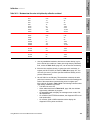
Modbus protocol supports up to 247 transmitters in a multidrop network.
Each transmitter must be assigned a unique address within the range
specified in Table 5-3, page 30. This procedure is described in
Chapter 5.
Using Modbus
Commands
To initiate communication with an individual network device, the host
controller uses the unique address of the network device. To initiate
communication with all the network devices, the host controller uses
command 0.
9
Measurement Units
Using Modbus® Protocol with Micro Motion® Transmitters
Outputs, Option Boards,
and Communications
Micro Motion calibrates each transmitter to operate with a particular
sensor. However, Modbus protocol enables interchange of transmitters
and sensors.
• You can recalibrate the transmitter for accurate measurement of flow,
density, and temperature with any compatible Micro Motion sensor.
• You can characterize the flowmeter's sensitivity to mass flow, density,
and temperature.
Sensor and Transmitter
Information
The host controller communicates with a network device by reading data
stored in the mapped addresses of the network device, each of which
corresponds to a specific memory location in the transmitter's
microprocessor. The host controller can query one mapped address or
multiple consecutive addresses of a single device, or can broadcast a
message to one mapped address or multiple consecutive addresses of
all the network devices.
Sensor and transmitter
interchangeability
Implementting
Modbus Protocol
The transmitter can accept, store, and return 32-bit floating-point values
and 8-bit ASCII characters, regardless of the data transmission mode
(ASCII or RTU) required by the host controller.
Introduction to
Modbus Protocol
Complete configuration, calibration, and flowmeter characterization
require use of floating-point values and ASCII characters supported by
some Modbus host controllers.
• Floating-point values must be written in a single command to a series
of two consecutive registers. More than one value can be written in a
single command.
• Character strings must be written in a single command to a series of
4 to 16 consecutive registers, depending on the number of
characters specified for the string. More than one character string
can be written in a single command.
Before You Begin
Introduction to Modbus Protocol with Micro Motion Transmitters continued
10
Using Modbus® Protocol with Micro Motion® Transmitters
Before You Begin
Introduction
3
Implementing Modbus Protocol
This chapter explains how to configure the transmitter to use Modbus®
protocol. The configuration procedure depends on the transmitter.
3.2
RS-485 requirements
All communication using Modbus protocol requires an RS-485
connection. Many, but not all, Micro Motion transmitters have an RS-485
digital output that can be used for this purpose. If an RS-485 digital
output is available, it can be used for either a temporary or a permanent
connection.
See Figure 3-5, page 16, for a diagram of the RS-485 digital output and
service port.
The core processor, which is a component of Series 1000, Series 2000,
and MVDSolo installations, also has RS-485 terminals. See Figure 3-6,
page 18.
RFT9739 transmitter
The procedure for implementing Modbus protocol with the RFT9739
transmitter depends on the transmitter version. Before you can
implement Modbus protocol, you must identify the transmitter version.
Transmitter version
identification
Using Modbus® Protocol with Micro Motion® Transmitters
11
Measurement Units
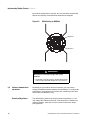
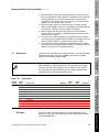
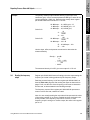
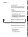
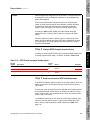
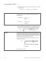
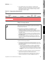
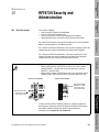
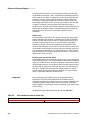
To identify the field-mount RFT9739 transmitter version:
1. Unscrew the cover from the base of the housing.
2. Inside the transmitter is an electronics module, which has terminal
blocks for wiring connections. A Version 3 transmitter has an
electronics module that is different from older versions. Earlier
versions of the module have switches labeled SELECT, CONTROL,
and EXT.ZERO. A module for a Version 3 transmitter does not have
these labels. For comparison, refer to Figure 3-1, page 12.
Outputs, Option Boards,
and Communications
There are three versions of the RFT9739 transmitter. You should not
have a transmitter that is earlier than Version 2. If the transmitter is
earlier than Version 2, contact Micro Motion. (See the back cover of this
manual for phone numbers.)
Sensor and Transmitter
Information
3.3
Using Modbus
Commands
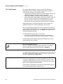
Some Series 1000 and Series 2000 transmitters do not have an RS-485
digital output. In this case, the service port under the transmitter’s
Warning flap can be used for temporary connections. Because of the
location of the service port, this connection is not appropriate for
permanent connections. Temporary connections are useful for
configuration or troubleshooting purposes.
Implementting
Modbus Protocol
About this chapter
Introduction to
Modbus Protocol
3.1
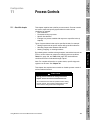
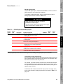
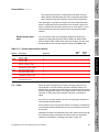
Implementing Modbus Protocol continued
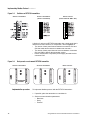
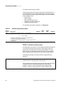
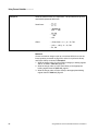
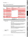
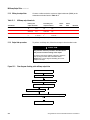
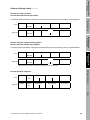
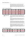
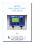
Figure 3-1.
Switches on RFT9739 transmitters
Version 3 transmitters
Version 2 transmitters
(switch 8 not labeled)
Earlier versions
(switch 8 labeled "BELL 202")
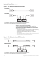
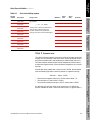
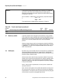
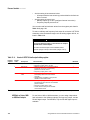
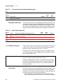
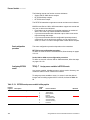
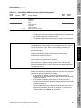
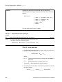
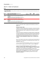
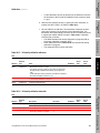
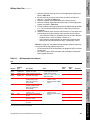
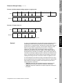
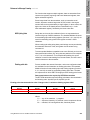
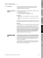
A Version 3 rack-mount RFT9739 transmitter has a back panel that is
different from older versions. For comparison, refer to Figure 3-2.
• The Version 3 back panel has text between connectors CN1 and
CN2 that reads BACKPLANE RFT9739RM PHASE 2/PHASE 3.
• The Version 2 back panel does not have text between connectors
CN1 and CN2 to identify the transmitter version.
• Earlier versions have a 3-position power-supply terminal block at
connector CN3.
Figure 3-2.
Back panels on rack-mount RFT9739 transmitter
Version 3 transmitters
Implementation procedure
Version 2 transmitters
Earlier versions
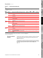
To implement Modbus protocol with the RFT9739 transmitter:
1. If possible, place the transmitter on a workbench.
2. Set three communications parameters:
• Baud rate
• Parity
• Protocol
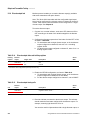
12
Using Modbus® Protocol with Micro Motion® Transmitters
Set the baud rate and parity as appropriate for your network. Set protocol to one of the options that includes Modbus on RS-485. Be sure
to select the correct data bits setting – RTU (8 bits) or ASCII (7 bits).
Introduction to
Modbus Protocol
These communications parameters can be set using either of two
methods:
• Via switches on the electronics module in the field-mount
transmitter or on the control board in the rack-mount transmitter
• Via the front-panel display on the rack-mount transmitter or the
optional display on the field-mount transmitter
Before You Begin
Implementing Modbus Protocol continued
Refer to the instruction manual that was shipped with the transmitter
for detailed instructions.
Implementting
Modbus Protocol
3. Install the flowmeter, making sure RS-485 wiring is properly
connected.
• For RS-485 wiring from the field-mount transmitter, see Wiring for
field-mount RFT9739 transmitter, below.
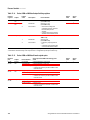
• For RS-485 wiring from the rack-mount transmitter, see "Wiring
for rack-mount RFT9739 transmitter," page 14.
WARNING
Using Modbus
Commands
Hazardous voltage can cause severe injury or death.
Shut off the power before wiring the transmitter.
WARNING
Sensor and Transmitter
Information
A transmitter that has been improperly wired or
installed in a hazardous area could cause an
explosion.
• Make sure the transmitter is wired to meet or exceed
local code requirements.
• Install the transmitter in an environment that complies
with the classification tag on the transmitter.
13
Measurement Units
Using Modbus® Protocol with Micro Motion® Transmitters
Outputs, Option Boards,
and Communications
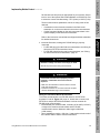
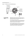
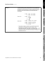
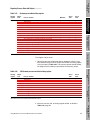
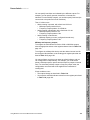
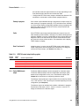
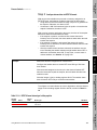
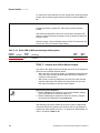
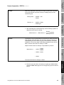
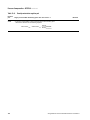
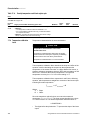
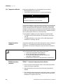
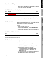
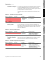
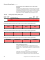
Wiring for field-mount RFT9739 transmitter
To connect the transmitter to an RS-485 network, use RFT9739
terminals 27 and 26. Figure 3-3, page 14, shows how to connect one
RFT9739 or multiple RFT9739 transmitters to a host controller for
RS-485 serial communication.
• Install twisted-pair, shielded cable, consisting of 24 AWG (0.25 mm²)
or larger wire, between the transmitter and an RS-485
communication device. Maximum cable length is 4000 feet
(1200 meters).
• Some installations require a 120-ohm, ½-watt resistor at both ends of
the network cable to reduce electrical reflections.
Implementing Modbus Protocol continued
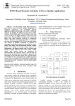
Figure 3-3.
RS-485 wiring for field-mount RFT9739 transmitter
One RFT9739 and
a host controller
A
Host
controller B
See note
See note
27
26
RFT9739
Multiple RFT9739s and
a host controller
A
Host
controller B
See note
See note
27
26
27
26
RFT9739
27
RFT9739
26
RFT9739
For long-distance communication, or if noise from an external source interferes with the
signal, install 120-ohm ½-watt resistors across terminals of both end devices.
Wiring for rack-mount RFT9739 transmitter
To connect the transmitter to an RS-485 network, use RFT9739
terminals CN2-Z22 and CN2-D22. Figure 3-4 shows how to connect
one RFT9739 or multiple RFT9739 transmitters to a host controller for
RS-485 serial communication.
• Install twisted-pair, shielded cable, consisting of 24 AWG (0.25 mm²)
or larger wire, between the transmitter and an RS-485
communication device. Maximum cable length is 4000 feet
(1200 meters).
• Some installations require a 120-ohm, ½-watt resistor at both ends of
the network cable to reduce electrical reflections.
Figure 3-4.
RS-485 wiring for rack-mount RFT9739 transmitter
One RFT9739 and
a host controller
Host
controller
A
See note
See note
B
Z22
D22
RFT9739
Multiple RFT9739s and
a host controller
Host
controller
A
See note
See note
Z22
D22
B
Z22
D22
RFT9739
Z22
RFT9739
D22
RFT9739
For long-distance communication, or if noise from an external source interferes with the
signal, install 120-ohm ½-watt resistors across terminals of both end devices.
14
Using Modbus® Protocol with Micro Motion® Transmitters
3.4
Series 1000 or 2000
transmitter
To implement Modbus protocol with the Series 1000 or 2000 transmitter:
2. Referring to the instruction manuals that were shipped with the
transmitter and sensor, install the flowmeter.
3. Make sure RS-485 wiring is properly connected. See Figure 3-5,
page 16.
5. If you are using the RS-485 terminals, configure the digital
communication variables listed in Table 3-1, page 17.
If you are communicating with the transmitter via terminals 5 and
6, ProLink II software will lose communication with the transmitter
at this point. Change the ProLink II communication settings and
re-establish communication.
b.
Using Modbus® Protocol with Micro Motion® Transmitters
15
Measurement Units
To install RS-485 point-to-point wiring, see Figure 3-5, page 16.
• Install twisted-pair, shielded cable, consisting of 24 AWG (0.25 mm²)
or larger wire, between the transmitter and an RS-485
communication device. Maximum cable length is 4000 feet
(1200 meters).
• Some installations require a 120-ohm, ½-watt resistor at both ends of
the network cable to reduce electrical reflections.
Outputs, Option Boards,
and Communications
Wiring for Series 1000 or
2000 transmitter
If you do not have ProLink II software, you can use the HART
Communicator (HART 275) or the transmitter display to set the
communication variables.
Sensor and Transmitter
Information
Changing the communication settings affects only terminals 5
and 6. It does not affect the mA/Bell 202 terminals (1 and 2) or
the service port (terminals 7 and 8).
Using Modbus
Commands
a. If you have ProLink II™ software, refer to Using ProLink II
Software with Micro Motion Transmitters, and use the software to
configure the digital communication variables.
• Set the address to 1.
• Click the Comm tab.
• Click one of the two Modbus options under Protocol.
• Click one of the six options under Baud Rate.
• Click one of the three options under Parity.
• Click one of the two options under Stop Bits.
• Click Apply.
Implementting
Modbus Protocol
4. If you are using the service port, the digital communications variables
are preset to a baud rate of 38,400, parity of none, 1 stop bit, and
address of 111.
Introduction to
Modbus Protocol
1. Make sure the transmitter has wiring terminals for RS-485 wiring. If
the transmitter does not have RS-485 wiring terminals, use the
service port under the Warning flap.
Before You Begin
Implementing Modbus Protocol continued
Implementing Modbus Protocol continued
Figure 3-5.
RS-485 wiring for Series 1000 or 2000 transmitter
Primary
Primary
controller
controller
Warning flap
Multiplexer
Multiplexer
RS-485
A
RS-485A
RS-485B
Power supply
Power supply
85–265 VAC,
85–265
50/60
HzVAC,
18–100
VDC
50/60
Hz
18–100 VDC
RS-485 B
Other
Other devices
devices
Series 1000 or 2000
digital communication
variables
Service port
Table 3-1 lists the digital communication variables that control network
communications. These variables must be set correctly to enable
Modbus communication. If you are connecting through the service port,
these variables are detected automatically.
After communication via Modbus protocol has been implemented, you
may use the Modbus host controller to change any of the communication
settings. To do this, write the integer code of the desired value to the
appropriate holding register, as listed in Table 3-1.
Note: If you change these values, you may lose your connection and
have to re-establish communication. If you have set them incorrectly, you
may be unable to re-establish Modbus communication. If this occurs,
you will need to reset these variables using another method (for
example, the HART Communicator or hardware switches)..
16
Using Modbus® Protocol with Micro Motion® Transmitters
Before You Begin
Implementing Modbus Protocol continued
Table 3-1.
Series 1000 or 2000 digital communication variable holding registers
Integer
code
Digital communication protocol codes
Series
1000
Series
2000
41132
0
None
Ö
Ö
1
2
3
HART only
Modbus RTU only
Modbus ASCII only
Ö
Ö
Ö
Ö
Ö
Ö
Ö
Ö
Ö
Ö
Ö
Ö
Ö
Ö
Ö
Ö
Ö
Ö
Ö
Ö
Ö
Ö
Ö
Ö
Ö
Ö
Ö
Ö
Introduction to
Modbus Protocol
Holding
register
Digital communication baud rate codes
41133
1200 baud
2400 baud
4800 baud
9600 baud
19,200 baud
38,400 baud
Implementting
Modbus Protocol
0
1
2
3
4
5
Digital communication parity codes
41134
0
1
2
None
Odd parity
Even parity
Digital communication stop bits
1
2
1 stop bits
2 stop bit
Using Modbus
Commands
41135
WARNING
Sensor and Transmitter
Information
Changing communication settings may terminate
your Modbus connection.
• Do not change the settings to values that are
incompatible with Modbus communication.
• Be prepared to re-establish communication after
changing settings.
MVDSolo
To enable Modbus protocol with MVDSolo:
1. Install twisted-pair, shielded cable, consisting of 24 AWG (0.25 mm²)
or larger wire, between MVDSolo and the remote RS-485
communication device. Maximum cable length is 1000 feet
(300 meters). See Figure 3-6, page 18. For more information, see
the sensor manual and Instructions for 4-Wire Cable and Gland
Preparation for Wiring at Core Processor, available from Micro
Motion.
Using Modbus® Protocol with Micro Motion® Transmitters
17
Measurement Units
2. Supply power to the core processor, using a “floating” (isolated) DC
power supply. See the sensor manual for more information.
Outputs, Option Boards,
and Communications
3.5
Implementing Modbus Protocol continued
No protocol configuration is required: the core processor automatically
detects the incoming communications parameters and adjusts.
Figure 3-6.
RS-485 wiring for MVDSolo
RS-485 B
RS-485 A
WARNING
Be careful to connect the wiring to the correct
terminals.
• Accidentally connecting power to the RS-485 terminals
of the core processor will damage the core processor.
3.6
18
Optional communication
parameters
Depending on your network and host controller, you may need to
change the default transmitter address (all transmitters), or configure the
transmitter to communicate with a slower host controller (Series 1000,
Series 2000, and MVDSolo only).
Default polling address
The default polling address for all Micro Motion transmitters is 1. You
may change this address as desired. If the transmitter is installed on a
multidrop network, each device on the network must have a unique
polling address.
Using Modbus® Protocol with Micro Motion® Transmitters
Before You Begin
Implementing Modbus Protocol continued
See Chapter 6 for instructions on changing the transmitter’s polling
address.
Table 3-2.
40522
Additional delay to response holding register
Integer value
MVDSolo
Series
1000
Series
2000
• An integer that represents the time required to synchronize communication
with a slower host controller
• For appropriate values, see Table 3-3 and the equation above
Ö
Ö
Ö
Implementting
Modbus Protocol
Holding
register
If you have MVDSolo or a Series 1000 or 2000 transmitter, you can
configure the transmitter to add a time delay, measured in milliseconds,
to each response it sends to a remote controller. To do this, write the
appropriate integer value for the additional response time delay to
holding register 40522, as listed in Table 3-2.
The register value that you should write is listed in Table 3-3 and is
based on the following equation:
Using Modbus
Commands
TimeDelay
Register Value = -----------------------------------------------------------------1200
6400 m sec ´ -------------------------Baud rate
Table 3-3.
Register values for additional response time delay
Baud rate:
1200 baud
2400 baud
Time delay
4800 baud
9600 baud
19,200 baud
38,400 baud
2
4
8
16
32
4
8
16
32
64
Register value to be written:
—
—
—
1
2
—
—
1
2
4
—
1
2
4
8
1
2
4
8
16
Sensor and Transmitter
Information
800 msec
1600 msec
3200 msec
6400 msec
12.8 msec
Introduction to
Modbus Protocol
Additional response time
delay
Outputs, Option Boards,
and Communications
19
Measurement Units
Using Modbus® Protocol with Micro Motion® Transmitters
20
Using Modbus® Protocol with Micro Motion® Transmitters
Before You Begin
Introduction
4
About this chapter
This chapter explains how to use Modbus commands that are supported
by Micro Motion transmitters. The transmitter can use integers, floatingpoint values, and ASCII character strings.
Introduction to
Modbus Protocol
4.1
Using Modbus Commands
CAUTION
Implementting
Modbus Protocol
Using write commands can change transmitter
outputs, which can result in measurement error.
Set control devices for manual operation before using
write commands. This prevents automatic recording of
process data during transmitter configuration.
Modbus commands are composed of function codes and references to
addresses in transmitter memory. These addresses contain values that
represent process data, transmitter configuration, and so on.
Appendix B provides reference information for Modbus command
structures. If you are using ProLink II software, the Modbus commands
are automatically coded and interpreted by the software.
4.3
Memory structures and
data types
The types of data written to and returned from the transmitter depend on
the capabilities of the host controller. The transmitter can accept, store,
and return binary data, integers, floating-point values, and ASCII
characters, regardless of the 8-bit RTU or 7-bit ASCII data transmission
mode used by the host controller.
Using Modbus® Protocol with Micro Motion® Transmitters
21
Measurement Units
In this manual, these memory structures are identified with 5-digit
numbers. The first digit represents the memory type, and the other four
identify the specific bit or register of that type. See Table 4-1, page 22.
Outputs, Option Boards,
and Communications
Transmitter memory is structured in several different ways:
• Binary data (0/1, OFF/ON) is stored in binary bit units called coils
(read/write) or discrete inputs (read-only).
• All other data types are stored in one or more registers. A register is
a 16-bit unit of memory.
- Integer values are stored in holding registers (read/write) or input
registers (read-only). Values are unsigned 16-bit integers ranging
from 0 to 65535.
- Floating-point values stored in register pairs, in single precision
IEEE 754 format. A register pair may be either read/write or readonly.
- ASCII values are stored in consecutive registers. Each register
holds one pair of 8-bit ASCII characters (16 bits total).
Sensor and Transmitter
Information
Message structure
Using Modbus
Commands
4.2
Using Modbus Commands continued
Table 4-1.
Memory structures, data formats, and numbering conventions
Name
Memory structure
Access
Data type
Typical use
Identifier
Coil
Bit
Read/write
Binary
0XXXX
Discrete
input
Input
register
Holding
register
Register
pair
ASCII
register
Bit
Read-only
Binary
Enable/disable functions, set/reset
controls
Store status information
16-bit register
Read-only
Integer
3XXXX
16-bit register
Read/write
Integer
16-bit register pair (32
bits total)
1 or more consecutive
16-bit registers
Read-only or
read/write
Read/write
Floating
point
8-bit ASCII
Store process variable data in integer
form
Store configuration data, device
identification codes, serial numbers
Store process variable data or
configuration data in floating-point format
Store alphanumeric data such as labels
for special measurement units.
Integer data support
1XXXX
4XXXX
2XXXX2XXXY
5XXXX
All Modbus host controllers support integer data, enabling you to
perform the following tasks:
• Reading values of process variables
• Reading transmitter status
• Establishing standard engineering units for all process variables
• Scaling integers that represent process variables
• Limited configuration of the transmitter
Integer data can be written to 16-bit holding registers. Integer data
include integer codes corresponding to choices from a software menu,
and integer values for scaling process variables.
An integer value is written to a holding register using a single command.
Multiple values can be written with a single command, if the holding
registers are consecutive. If they are non-consecutive, a separate
command must be used for each holding register.
Integer values are read using a single command to read a holding
register or several consecutive holding registers. You can configure slot
addresses to allow you to read multiple non-consecutive holding
registers using a single command. See Chapter 16 for information on
configuring slot addresses.
Floating-point data
support
Some Modbus-compatible host controllers support floating-point values.
Floating-point values are stored in register pairs. Each register pair
consists of two consecutive 16-bit registers and can return values as
small as 9.999999 x 10⁻³² or as large as 9.999999 x 1032 with 23-bit
resolution, 1-bit sign, and 8-bit exponent. The digital value displayed on
a readout depends on the host controller.
The byte order of floating-point values can vary depending on your
transmitter:
22
Using Modbus® Protocol with Micro Motion® Transmitters
•
•
If you are using an RFT9739 transmitter, the byte order is fixed.
If you are using MVDSolo or a Series 1000 or 2000 transmitter, the
byte order is configurable.
A floating-point value is written to a register pair using a single
command. Multiple values can be written with a single command, if the
register pairs are consecutive. If they are non-consecutive, a separate
command must be used for each pair.
ASCII data support
Consecutive ASCII registers can be read using a single read command.
You can configure slot addresses to allow you to read multiple nonconsecutive ASCII registers using a single command. See Chapter 16
for information on configuring slot addresses.
For process variables, the value read from the sensor is available in both
floating-point and integer format:
• If you read the input register associated with the process variable,
the transmitter will return an integer.
• If you read the floating-point register pair associated with the process
variable, the transmitter will return a floating-point value.
Similarly, for certain configuration variables, the value to be stored in
transmitter memory is in integer format, while for other configuration
variables the value is in floating-point format. In the first case, the value
is written to a holding register; in the second case, the value is written to
a floating-point register pair.
23
Measurement Units
Using Modbus® Protocol with Micro Motion® Transmitters
Outputs, Option Boards,
and Communications
Note that there is no necessary correspondence between the identifiers
assigned to the floating-point register pair and the input or holding
register: The floating-point register pair may be 20195-20196 while the
other register is 40039 (a holding register in this case, as denoted by the
4).
Sensor and Transmitter
Information
Reading and writing data
Using Modbus
Commands
Some Modbus-compatible host controllers support ASCII values. ASCII
values are stored in ASCII registers. Two 8-bit characters can be stored
in each 16-bit register. Character strings must be written in a single
command to a series of four to 16 consecutive registers, depending on
the number of characters specified for the string. More than one
character string can be written in a single command.
Implementting
Modbus Protocol
Floating-point values are read using a single command to read a register
pair, or several consecutive register pairs. You can configure slot
addresses to allow you to read multiple non-consecutive register pairs
using a single command. See Chapter 16 for information on configuring
slot addresses.
Introduction to
Modbus Protocol
See Appendix B for more information on byte order.
Before You Begin
Using Modbus Commands continued
Using Modbus Commands continued
4.4
Enumerated integers
Some holding registers store enumerated integers, which consist of
integer codes.
Integer codes
Integer codes correspond to options available from a list. The following
example describes how to use an integer code:
Example
Establish grams per second (g/sec) as the measurement unit for the
mass flow rate.
Integer code 70 corresponds to g/sec, and holding register 40039
stores the integer for the mass flow rate unit.
Write the integer 70 to holding register 40039. The transmitter will
measure and return the mass flow rate in g/sec.
Values dependent on
integer codes
Example
Some integer or floating-point values depend on integer codes held
elsewhere in the map. The following example describes a variable with a
floating-point value that depends on an integer code for a measurement
unit.
To establish grams per second (g/sec) as the measurement unit for the
mass flow rate, the integer 70 has been written to holding register
40039, as illustrated in the example on page 24. The transmitter should
indicate zero flow if the mass flow rate drops below 0.50 g/sec.
Register pair 20195-20196 stores the mass flow cutoff for the
frequency and digital outputs.
Write a value of 0.50 to register pair 20195-20196. The frequency and
digital outputs will indicate zero flow if the mass flow rate drops below
0.50 g/sec.
4.5
Linearity and proportion
Proper use of Modbus commands requires an understanding of how the
transmitter derives linear outputs that are proportional to the process
data it receives.
To calculate an output proportional to process data, the transmitter uses
the following equation:
y = Ax + B
24
Using Modbus® Protocol with Micro Motion® Transmitters
Example
A 4-20 mA output represents a density of 0.0000 to 5.0000 grams per
cubic centimeter (g/cc). Determine the slope and offset of the output.
Implementting
Modbus Protocol
You can manipulate the linear equation to perform the following tasks:
• Implementing unit conversions and integer scaling of process
variables
• Establishing frequency output scaling
• Determining the value of a process variable represented by a
milliamp or frequency output
• Calibrating or characterizing the flowmeter for optimal measurement
of flow, density, and temperature
Introduction to
Modbus Protocol
Where:
y = Output level that represents x value of process variable
A = Slope, or proportional change in the output that occurs due to
a given change in process variable
x = Value of process variable at output level y
B = Offset, or output when process variable has a value of 0
Before You Begin
Using Modbus Commands continued
20 Milliamps = A ( 5.0000 g/cc ) + B
4 Milliamps = A ( 0.0000 g/cc ) + B
Solve for A:
16 Milliamps = A ( 5.0000 g/cc )
Using Modbus
Commands
16
A = -----5
A = 3.2
Solve for B:
20 Milliamps = 3.2 ( 5.0000 g/cc ) + B
20 – 16 = B
B = 4
Sensor and Transmitter
Information
The output has a slope of 3.2 (A = 3.2) and an offset of 4 (B = 4).
Outputs, Option Boards,
and Communications
25
Measurement Units
Using Modbus® Protocol with Micro Motion® Transmitters
26
Using Modbus® Protocol with Micro Motion® Transmitters
Before You Begin
Configuration
5
Overview
This chapter explains how to write sensor and transmitter information.
With one exception, the procedures described in this chapter are
optional. The ability to store sensor information in the transmitter is
provided as a convenience to the user.
CAUTION
Writing sensor and transmitter information can
change transmitter outputs, which can result in
measurement error.
5.2
The core processor can store basic information about the sensor.
Holding registers 40047-40051 and 40127-40131 store sensor
description data as integer values. Some registers store integer codes
corresponding to options available from a list. In some cases, two
consecutive registers are combined to store integers larger than 65535.
Sensor serial number
Write the sensor serial number to register pair 40127-40128. The sensor
serial number can be found on the metal tag on the sensor housing.
Because the sensor serial number is a 24-bit number, two registers are
required. The serial number is stored in the low order 8 bits of register
40127 plus all 16 bits of register 40128. The high order 8 bits of register
40127 must be set to 0. See Table 5-1, page 28.
27
Measurement Units
Using Modbus® Protocol with Micro Motion® Transmitters
Outputs, Option Boards,
and Communications
Sensor description
Sensor and Transmitter
Information
Set control devices for manual operation before writing
sensor and transmitter information.
Using Modbus
Commands
The exception is network address, or polling address. The default polling
address is 1. If your transmitter is installed in a multidrop network, you
must specify a unique polling address for the transmitter to enable
communication with the controller.
Implementting
Modbus Protocol
Sensor and transmitter information consists of integer data and ASCII
character strings that provide data about the flowmeter. You can review
or change most, but not all, sensor and transmitter information without
affecting operation of the flowmeter. The host controller uses the tag and
the polling address to communicate with the transmitter.
Introduction to
Modbus Protocol
5.1
Sensor and Transmitter
Information
Sensor and Transmitter Information continued
Table 5-1.
Sensor serial number register pair
Register
Bits
Value
MVDSolo
Series
1000
Series
2000
RFT9739
40127
High order 8 bits
00000000
Ö
Ö
Ö
Ö
40128
Low order 8 bits
All 16 bits
First 8 bits of sensor serial number
Last 16 bits of sensor serial number
Ö
Ö
Ö
Ö
Ö
Ö
Ö
Ö
Sensor physical
description
Table 5-2.
Holding
register
40129
Write integer codes describing the sensor to the holding registers listed
in Table 5-2.
Sensor information holding registers
Integer
code
0
1
2
5
7
8
9
10
11
12
251
252
253
Ö
Ö
Ö
Ö
Ö
Ö
Ö
Ö
Ö
Ö
Series
1000
Ö
Ö
Ö
Ö
Ö
Ö
Ö
Ö
Ö
Ö
Series
2000
Ö
Ö
Ö
Ö
Ö
Ö
Ö
Ö
Ö
Ö
Ö
Ö
Ö
Ö
Ö
Ö
Ö
Ö
Ö
Ö
Ö
Ö
Ö
Ö
Ö
Ö
Ö
Ö
Ö
Ö
Ö
Ö
Ö
Ö
Ö
Ö
Ö
Ö
Ö
Ö
Ö
Ö
Ö
Sensor flange type codes
MVDSolo
ANSI 150
ANSI 300
ANSI 600
PN 40
JIS 10K
JIS 20K
ANSI 900
Sanitary clamp
Union
PN 100
None
Unknown
Special
RFT9739
Ö
Ö
Ö
Ö
Ö
Ö
Ö
Ö
Ö
Ö
Ö
Ö
FLow tube construction material codes
40130
3
4
5
6
19
23
252
253
Hastelloy® C-22
Monel
Tantalum
Titanium
316L stainless steel
Inconel™
Unknown
Special
Ö
Ö
Ö
Flow tube liner material codes
40131
10
11
PTFE (Teflon®)
Halar
Ö
Ö
Ö
Ö
Ö
Ö
Ö
Ö
16
251
252
253
Tefzel®
None
Unknown
Special
Ö
Ö
Ö
Ö
Ö
Ö
Ö
Ö
Ö
Ö
Ö
Ö
Ö
Ö
Ö
Ö
Ö
Ö
Ö
Ö
Sensor type codes
41139
0
1
28
Curved-tube sensor (D, DL, DT, CMF, F-Series, RSeries)
Straight-tube sensor (T-Series)
Using Modbus® Protocol with Micro Motion® Transmitters
Before You Begin
Sensor and Transmitter Information continued
5.3
Transmitter description
Some transmitter information is configurable. Other information is not
configurable, but can be read by the customer.
Introduction to
Modbus Protocol
Configurable information includes:
• HART polling address (RFT9739 transmitter only)
• Modbus polling address
• HART protocol device tag
• Transmitter final assembly number
• User-specified date
• User-specified messages or descriptions
Table 5-3, page 30. and Table 5-4, page 31. list the configurable items
and the associated holding registers (for integer values) or ASCII
registers (for character strings). For each item, write the appropriate
value to the specified holding register or ASCII register(s).
Note: If you are using HART protocol via the Bell 202 physical layer, an
address of 0 is required to allow the milliamp output variable to represent
a process variable. This may have implications for network layout if you
plan to use multiple flowmeters configured for output variables.
Using Modbus
Commands
Table 5-5, page 32, lists the non-configurable items and the associated
input registers. To read these items, read the appropriate input register.
Implementting
Modbus Protocol
Non-configurable information includes:
• Transmitter software revision
• Electronics module identifier
• Core processor software revision
• Transmitter output option board
Sensor and Transmitter
Information
Outputs, Option Boards,
and Communications
29
Measurement Units
Using Modbus® Protocol with Micro Motion® Transmitters
Sensor and Transmitter Information continued
Table 5-3.
Holding
register
Configurable transmitter information – integer values
Description
Integer value
40047
HART or
Modbus polling
address
40048
Final assembly
number from tag
on transmitter
housing
• Any integer from 0 to 15 that identifies this
RFT9739 transmitter in a multidrop
network
• For HART protocol via the Bell 202
physical layer:
- An address other than 0 fixes the
primary milliamp output at 4 MA
- An address of 0 enables the primary
milliamp output to represent a process
variable
High-order register of integer from 0 to
167777215
Low-order register of integer from 0 to
167777215
Day (any integer from 01 to 31)
Month (any integer from 01 to 12),
multiplied by 256, plus year (any integer
from 00 to 99)
An integer that identifies this transmitter in a
Modbus multidrop network:
• 1-247 for RFT9739 transmitter
• 1-15, 32-47, 64-79, 96-110 for MVDSolo
or Series 1000 or 2000 transmitter
High order register of 3-byte integer
Low-order register of 3-byte integer
40049
40050
40051
Date (day/
month/year)
40313
Modbus polling
address
41187
41188
Core processor
I.D.2, 3
Series
1000
Series
2000
RFT9739
Ö
Ö
Ö1
Ö
Ö
Ö
Ö
Ö
Ö
Ö
Ö
Ö
Ö
Ö
Ö
Ö
Ö
Ö
Ö
Ö
Ö
Ö
Ö1
Ö
Ö
Ö
Ö
MVDSolo
1 Version
3.7 and higher revision RFT9739 transmitters.
be queried through transmitter. If wiring is direct to core processor, registers 41187 and 41188 do not exist.
3 Same as registers 31187-31188, listed in Table 5-5, page 32. If these registers contain a non-zero value, they are read-only. If
they contain 0, they can be written to.
2 Must
30
Using Modbus® Protocol with Micro Motion® Transmitters
Before You Begin
Sensor and Transmitter Information continued
Table 5-4.
Configurable transmitter information – character strings
Note
Introduction to
Modbus Protocol
Write character strings as single-write multiples.
ASCII character string
MVDSolo
Series
1000
Series
2000
RFT9739
50068
50069
50070
50071
50096
50097
50098
50099
50100
50101
50102
50103
50104
50105
50106
50107
50108
50109
50110
50111
50112
50113
50114
50115
50116
50117
50118
50119
50425
50426
50427
50428
50429
50430
50431
50432
Device tag
Each register holds 2 characters in an 8character tag that identifies this transmitter in
a HART multidrop network
Ö
Ö
Ö
Ö
Transmitter
description
• Each register holds 2 characters in a 16character device description or other
message
• Description is for user information only, and
is not used by the transmitter
Ö
Ö
Ö
Ö
Message
• Each register holds 2 characters in a 32character message
• Message is for user information only, and is
not used by the transmitter
Ö
Ö
Ö
Ö
Sensor
description
• Each register holds 2 characters in a 16character description of the sensor, for
example, sensor model number
• Sensor description is for user information
only, and is not used by the transmitter
Ö
Ö
Ö
Using Modbus
Commands
Description
Implementting
Modbus Protocol
Register
Sensor and Transmitter
Information
Outputs, Option Boards,
and Communications
31
Measurement Units
Using Modbus® Protocol with Micro Motion® Transmitters
Sensor and Transmitter Information continued
Table 5-5.
Input
register
30016
30121
30122
Non-configurable transmitter information
Description
Returned integer
MVDSolo
Series
1000
Series
2000
RFT9739
Transmitter
software
revision
Identification
number from tag
on electronics
module
Hart protocol
device identifier1
An integer describing the transmitter
software revision
Ö
Ö
Ö
Ö
1-byte integer that identifies this electronics
module
Ö
Ö
Ö
Ö
High-order register of integer from 0 to
167777215
Low-order register of integer from 0 to
167777215
1-byte integer describing software revision
for core processor
Ö
Ö
Ö
Ö
Ö
Ö
Ö
Ö
Ö
Ö
Ö
Ö
Ö
Ö
Ö
Ö
30123
31137
31138
31187
31188
Core processor
software
revision
Output option
board
Core processor
I.D.2 3
0
None
1
Analog I/O
2
FOUNDATION™ Fieldbus, Profibus-PA
3
Intrinsically safe output (IS)
4
Configurable input/output
High-order register of 3-byte integer
Low-order register of 3-byte integer
1 If
wiring is connected to transmitter, returns I.D. of transmitter. If wiring is connected to core processor, returns I.D. of core
processor.
2 Must be queried through transmitter. If wiring is direct to core processor, registers 31187 and 31188 do not exist.
3 Same as registers 41187-41188, listed in Table 5-3, page 30. If these registers contain a non-zero value, they are read-only. If
they contain 0, they can be written to.
32
Using Modbus® Protocol with Micro Motion® Transmitters
Before You Begin
Configuration
6
About this chapter
This chapter describes the different outputs that are available with each
transmitter, including the different outputs provided by the Series 1000
and 2000 transmitter option boards.
Sensor and Transmitter
Information
Uses of outputs
When you have established your outputs as described in this chapter,
you can use them in several ways:
• You can use outputs to report process data to a host controller.
Configuration instructions are provided in Chapter 9.
• You can use outputs for process control (Chapter 10).
• You can use outputs as fault indicators (Chapter 11).
Outputs
Different transmitters have different outputs. Additionally, the Series
1000 and Series 2000 transmitters have option boards, and each option
board has different outputs. The specific option board installed in your
transmitter will affect the feature set available to you.
Output types
The following terms are used to describe the different output types.
Using Modbus® Protocol with Micro Motion® Transmitters
33
Measurement Units
Milliamp (mA)
Outputs an electrical signal that varies in proportion to the value of its
assigned process variable.
Outputs, Option Boards,
and Communications
6.2
Using Modbus
Commands
This chapter also describes various communication options that may
apply to all transmitters, including:
• Changing the polling address and device tag
• Configuring burst mode
• Configuring polling to read external temperature or pressure
Implementting
Modbus Protocol
The chapter then discusses how you can use Modbus protocol to
configure the Series 2000 option boards. Configurable options include:
• Channel configuration (configurable input/output option boards only)
• Power source (configurable input/output option boards only)
• Frequency output mode (configurable input/output option boards
only)
• Frequency output polarity (intrinsically safe option boards or
configurable input/output option boards only)
• Configuring the frequency output as a discrete output
• Fieldbus simulation mode (Fieldbus option boards only)
• Profibus-PA station address (Fieldbus option boards with Profibus-PA
software loaded only)
Introduction to
Modbus Protocol
6.1
Outputs, Option Boards, and
Communications
Outputs, Option Boards, and Communications continued
Frequency
Outputs an electrical pulse at a rate that varies in proportion to the value
of its assigned process variable.
Analog
Refers to any output that varies in proportion to its assigned process
variable. In this context, “analog” typically refers to the milliamp output.
Discrete
A two-state output, frequently used to report ON/OFF states. Typically
implemented as two different steady electrical voltages: 0 (ON) and 15
(OFF). If you have a Series 2000 transmitter with the configurable
input/output board, you can reverse these settings (see Section 6.3).
RS-485 digital
Communicates digital (numeric) information using a communications
protocol, for example, Modbus. The numeric information can be the
value of an assigned process variable, or a variety of other data.
Unlike the other outputs discussed here, the RS-485 digital output does
not automatically send data. An external device can use this output to
query the transmitter.
Outputs, transmitters, and
option boards
Table 6-1.
Table 6-1 lists the outputs supplied with each transmitter and option
board. Configuration tables in this manual refer to these option board
types.
Transmitters, option boards, and outputs
Series 1000
Output
Milliamp
Frequency
RS-485 digital
RFT9739
control output
Discrete output
Discrete input
Series 2000
Analog
option board
IS option
board
Analog
option board
IS option
board
Configurable IO
option board1
1
12
1
1
12
1
13
1
2
13
1 or 2
0, 1, or 24
0 or 15
0 or 15
0, 1, or 2
0 or 1
RFT9739
2
1
1
1
1 See
"Series 2000 configurable input/output board," page 35.
reports same process variable as milliamp output.
3 May report same or different process variable as milliamp output.
4 All frequency outputs report the same process variable. See "Series 2000 configurable input/output board," page 35.
5 Depends on option board configuration.
2 Always
34
Using Modbus® Protocol with Micro Motion® Transmitters
6.3
Series 2000 configurable
input/output board
The configurable input/output board has three output channels. Channel
A is always a milliamp output; channels B and C are configurable, as
described in Table 6-2.
Additionally, if you configure either channel B or C as a frequency
output, you can specify the frequency output mode (phase shift) and
polarity of the output.
1. Write the integer code for the output type to holding register 41167,
for channel B, or holding register 41168, for channel C. Output type
codes are listed in Table 6-3.
Table 6-2.
Series 2000 configurable input/output board channel configuration
Channel
Output type integer codes
41166
41167
A
B
41168
C
0
0
1
4
1
4
5
Milliamp output
Milliamp output
Frequency output
Discrete output
Frequency output
Discrete output
Discrete input
Series
2000
Using Modbus
Commands
Holding
register
Ö
Ö
Ö
Series 2000 configurable input/output board power source configuration
Holding
register
Channel
Power source integer codes
41174
41175
B
C
0
1
External
Internal
Ö
Ö
35
Measurement Units
Using Modbus® Protocol with Micro Motion® Transmitters
Series
2000
Outputs, Option Boards,
and Communications
2. Write the integer code for the output power source to holding register
41174, for channel B, or holding register 41175, for channel C. Power
source also controls how the discrete outputs (if any) indicate
ON/OFF. Power source integer codes are listed in Table 6-3.
ON/OFF indicators are listed in Table 6-4, page 36.
Sensor and Transmitter
Information
If you specify frequency output for both channel B and channel C
(dual pulse), the channel C output is generated from the same signal
sent on Channel B. The channel C output is electrically isolated but
not independent. This configuration supports phase-shifting, discussed below.
Table 6-3.
Implementting
Modbus Protocol
To configure channels B and C:
Introduction to
Modbus Protocol
Channel A always uses an internal power source. Channels B and C
may be configured to use either an internal or an external power source.
This configuration also controls how the discrete outputs will report ON
or OFF.
Before You Begin
Outputs, Option Boards, and Communications continued
Outputs, Option Boards, and Communications continued
Table 6-4.
Series 2000 configurable input/output board discrete output voltages
Power source
State
Voltage
Series
2000
External
ON
15 V
Ö
Internal
OFF
ON
OFF
0V
0V
15 V
Ö
Ö
Ö
3. If you configured a frequency output in step 1, write the integer code
for the frequency output mode to holding register 41181. Frequency
output mode codes are listed in Table 6-5.
If you specified frequency output for both channel B and channel C
(dual pulse mode), the frequency output mode specified here applies
to both; they cannot be configured independently. If you specified
only one frequency output, you must specify 0 (single) here.
Table 6-5.
Holding
register
41181
Series 2000 configurable input/output board frequency output mode configuration
Frequency output mode integer codes
0
1
2
3
4
5
Single
Quadrature
Dual pulse w/ 0° phase shift
Dual pulse w/ 180° phase shift
Dual pulse w/ +90° phase shift
Dual pulse w/ -90° phase shift
Series
2000
Ö
Frequency output mode controls phase-shifting. For example, when
you set the outputs for quadrature, forward flow is indicated by a +90°
phase shift, and reverse flow is indicated by a -90° phase shift.
Quadrature mode is used only for specific Weights and Measures
applications where required by law.
4. If you configured a discrete input in step 1, you can configure it to
zero the flowmeter or reset a totalizer. Write the integer code of the
desired function to holding register 41176, as listed in Table 6-6.
Then connect a control device to channel C.
Table 6-6.
Discrete input assignment codes
Holding
register
Integer
code
Description
41176
0
1
2
3
4
None
Start flowmeter zero
Reset mass total
Reset volume total
Reset corrected volume total
1 Transmitters
36
Series
20001
Ö
with the configurable input/output option board only.
Using Modbus® Protocol with Micro Motion® Transmitters
6.4
Series 2000 frequency
output polarity
If you set both channels B and C on the configurable input/output
board to frequency, this setting applies to both; they cannot be configured separately.
Table 6-7.
41197
6.5
Series 2000 frequency output polarity configuration
Frequency output polarity integer codes
0
1
Ö
Active low
Active high
Series 2000 discrete
output
Series
2000
If you have a Series 2000 transmitter with the analog option board or the
intrinsically safe option board, you can configure the frequency output to
act as a discrete output. (If you have a Series 2000 transmitter with the
configurable input/output board, see Section 6.3, page 35.)
Using Modbus
Commands
To configure the frequency output as a discrete output, write integer
code 4 to holding register 41167, as listed in Table 6-8.
Table 6-8.
41167
6.6
Series 2000 discrete output configuration
Frequency output assignment integer codes
1
4
Ö
Frequency output
Discrete output
Configuring
communications
Series
2000
The transmitter uses network communications to exchange data with a
host controller or similar device, and may also use network
communications to poll an external device for temperature or pressure.
In all cases, the transmitter must have a unique address so that it can be
queried by external devices.
If HART protocol is used, burst mode may or may not be enabled.
If the transmitter will poll an external device for temperature or pressure,
polling must be configured. Polling requires HART protocol.
37
Measurement Units
Using Modbus® Protocol with Micro Motion® Transmitters
Outputs, Option Boards,
and Communications
Two protocols can be used for network communications:
• HART protocol
• Modbus protocol
Sensor and Transmitter
Information
Holding
register
Implementting
Modbus Protocol
Holding
register
Introduction to
Modbus Protocol
If you have the configurable input/output option board with a frequency output configured, or the intrinsically safe option board, you
can specify the polarity of the frequency output: active high or active
low. The default polarity, active high, is appropriate for most applications. Write the integer code for frequency output polarity to holding
register 41197, as shown in Table 6-7.
Before You Begin
Outputs, Option Boards, and Communications continued
Outputs, Option Boards, and Communications continued
Polling address
Polling addresses are integers assigned to transmitters to distinguish
them from other devices on multidrop networks. Each transmitter on a
multidrop network must have a polling address that is different from the
polling addresses of other devices on the network. Transmitters can be
configured for polling via HART protocol, Modbus protocol, or both.
HART protocol
If HART protocol is used to query the transmitter, it can be identified by
its polling address, configured in holding register 40047, or its device
tag, configured in ASCII registers 50068-50071. Configure either or
both, depending on how external devices will query this transmitter.
To configure the transmitter for HART polling, write the assigned
address and/or the assigned device tag to the appropriate register(s), as
shown in Table 6-9.
Table 6-9.
Address
40047
50068
50069
50070
50071
Transmitter polling via HART protocol
Address
type
Holding
register
ASCII
register
Series
1000
I.D. type
Description
Polling address
Valid addresses: 0-15
Device tag
ASCII character string. Each register
holds 2 characters in an 8-character
tag.
Ö
Series
2000
RFT9739
Ö
Ö
Ö
Ö
Transmitters that are polled via HART protocol can have polling
addresses of 0–15. Using HART protocol, 0 is a special-purpose polling
address that enables the primary mA output to vary according to a
process variable. When a transmitter’s HART polling address is set to
any value other than zero, the primary mA output is fixed at 4 mA.
Modbus protocol
If Modbus protocol is used to query the transmitter:
• For Series 1000 and 2000 transmitters, and for Version 3.7 and
higher RFT9739 transmitters, the transmitter is identified by the
polling address in holding register 40313.
• For Version 3.6 and lower RFT9739 transmitters, the polling address
is configured in holding register 40047.
Valid addresses for Modbus protocol depend on the transmitter type and
version, as shown in Table 6-10. To configure the polling address for
Modbus protocol, write the assigned address to the appropriate holding
register, also shown in Table 6-10.
38
Using Modbus® Protocol with Micro Motion® Transmitters
Before You Begin
Outputs, Option Boards, and Communications continued
Table 6-10.
Transmitter polling via Modbus protocol
I.D. type
Valid addresses
40313
Polling address
1-247
40047
Polling address
1-15, 32-47, 64-79, 96-110
1-15
1 Version
2 Version
MVDSolo
Series
1000
Series
2000
RFT9739
Introduction to
Modbus Protocol
Holding
register
Ö1
Ö
Ö
Ö
Ö2
3.7 and higher.
3.6 and lower.
Burst mode
Note: The RFT9739 transmitter supports burst mode, but it is not
configurable via Modbus.
Implementting
Modbus Protocol
Burst mode is a specialized mode of communication during which the
primary mA output is fixed at 4 mA and the transmitter regularly
broadcasts HART digital information. Because no polling by an external
host is required, burst mode can provide better performance. Burst
mode can be used only if the same process data will be broadcast each
time.
Burst mode is ordinarily disabled, and should be enabled only if another
device on the network requires HART burst-mode communication.
You can specify several types of process data to be sent via burst mode.
The data will be sent out via Bell202 HART at approximately 2-second
intervals. The interval is not configurable.
Sensor and Transmitter
Information
To configure HART burst mode:
1. Enable burst mode by setting coil 00083, as shown in Table 6-11.
Table 6-11.
HART burst mode control coil
Address
Description
Bit status
00083
HART burst mode is disabled
HART burst mode is enabled
0
1
Series
1000
Series
2000
Ö
Ö
Outputs, Option Boards,
and Communications
2. Specify the process data to be sent by writing an integer code to
holding register 41165, as shown in Table 6-12.
Table 6-12.
Holding
register
41165
HART burst mode process data
Description
1
2
3
33
Send primary variable
Send primary variable current and percent of range
Send dynamic variables and primary variable current
Send transmitter variables
Using Modbus® Protocol with Micro Motion® Transmitters
Series
1000
Series
2000
Ö
Ö
39
Measurement Units
Code
Using Modbus
Commands
Burst mode does not require specification of a target. Data broadcast in
burst mode can be received by any device that is listening.
Outputs, Option Boards, and Communications continued
3. If you specified code 33, send transmitter variables, you must
additionally specify up to four process variables to be burst. Write
integer codes for these process variables to holding registers 4116941172, as shown in Table 6-13.
Table 6-13.
HART burst mode code 33 process variables
Holding
register
Description
Process variable code
41169
41170
41171
41172
Burst variable 1
Burst variable 2
Burst variable 3
Burst variable 4
0
1
2
3
4
5
6
7
6.7
Polling external device
Mass flow rate
Temperature
Mass totalizer
Density
Mass inventory
Volume flow rate
Volume totalizer
Volume inventory
Series
1000
Series
2000
Ö
Ö
Ö
Ö
Ö
Ö
Ö
Ö
A Micro Motion transmitter can poll an external device to retrieve
information such as temperature or pressure. This can be used for realtime pressure or temperature compensation. Polling is performed using
HART protocol.
Configuration for external polling depends on your transmitter type and
version. MVDSolo does not support external polling.
Note: Complete implementation of pressure or temperature
compensation requires additional steps:
• See Chapter 12 for information on Series 1000 or Series 2000
pressure compensation.
• See Chapter 13 for information on RFT9739 pressure
compensation.
• See Chapter 14 for information on Series 1000 or Series 2000
temperature compensation.
Series 1000 and Series
2000 transmitter
A Series 1000 or 2000 transmitter, Version 2 and earlier, can be
configured to poll an external HART device for pressure. A Series 1000
or 2000 transmitter, Version 3 and later, can be configured to poll one or
two external HART devices, and can poll for pressure or temperature.
For example, you may poll device #1 for temperature and device #2 for
pressure.
To do this:
1. Write the polling tag of HART device #1 to registers 50298-50301.
Write the polling tag of HART device #2 to registers 51140-51153.
See Table 6-14.
2. Set the polling control code to identify the type of polling control. You
can specify a value of 0 (no polling), 1 (polling as a HART primary
master), or 2 (polling as a HART secondary master). Write the
40
Using Modbus® Protocol with Micro Motion® Transmitters
Before You Begin
Outputs, Option Boards, and Communications continued
Table 6-14.
External HART device polling tag
Notes
Write character strings as single-write multiples.
Series
2000
RFT9739
Each register holds 2 characters in a string of 8 characters that represent the
polling tag for external HART device #1.
Ö
Ö
Ö1
Each register holds 2 characters in a string of 8 characters that represent the
polling tag for external HART device #2
Ö2
Ö2
ASCII character strings
50298
50299
50300
50301
51140
51141
51142
51142
2 Version
Implementting
Modbus Protocol
1 Version
Introduction to
Modbus Protocol
Series
1000
Register
3 and later transmitters only.
3 and later transmitters only.
polling control code to holding register 40302, for device #1, or to
holding register 41144, for device #2. See Table 6-15.
Table 6-15.
Polling control type – Series 1000 and 2000
External
polling device
Integer
code
Description
40302
41144
Device #1
Device #2
0
1
2
No polling
Polling as a HART primary master
Polling as a HART secondary master
1 Version
Series
1000
Series
2000
Ö
Ö1
Ö
Ö1
3 and later transmitters only.
3. Specify the type of external data to be polled by writing the
appropriate integer code to holding register 41145, for device #1, or
to holding register 41146, for device #2. Transmitter versions 2 and
earlier can poll only for pressure. See Table 6-16.
Polled data – Series 1000 and 2000
Holding
register
External
polling device
Integer
code
Description
41145
41146
Device #1
Device #2
53
551
Pressure
Temperature
1 Version
Outputs, Option Boards,
and Communications
Table 6-16.
Series
1000
Series
2000
Ö
Ö1
Ö
Ö1
3 and later transmitters only.
41
Measurement Units
4. If you are using Version 3 or later of the Series 1000 or 2000
transmitter, skip this step. If you are using Version 2 of the Series
1000 or 2000 transmitter, specify pressure compensation by writing
integer code 1 to holding register 41147. See Table 6-17, page 42.
Using Modbus® Protocol with Micro Motion® Transmitters
Sensor and Transmitter
Information
Holding
register
Using Modbus
Commands
If you specify either 1 or 2 for device #1 polling control, you must
specify the same value for device #2. If you specify a different value,
the transmitter will operate as a HART primary master (polling control type 1) for both devices.
Outputs, Option Boards, and Communications continued
Table 6-17.
Polling type – Series 1000 and 2000, Version 2 and earlier
Holding
register
Integer code
Description
Series
1000
Series
2000
41147
1
Pressure compensation
Ö1
Ö1
1 Version
2 and earlier transmitters only.
RFT9739 transmitter
If you are using the RFT9739 transmitter, you may poll one external
device for pressure data. Polling for temperature data is not supported.
To configure polling for pressure data:
1. Write the external HART device polling tag to ASCII registers 5029850301, as listed in Table 6-14, page 41.
2. Set the polling control code to identify the type of polling control.
Write the polling control code to holding register 40302, as listed in
Table 6-18.
Table 6-18.
Polling control type – RFT9739
Holding
register
External
polling device
Integer
code
Description
RFT9739
40302
Device #1
0
3
4
5
8
No polling
Polling as a HART primary master
Polling as a HART secondary master
Analog input
Modbus
Ö
6.8
Fieldbus simulation mode
If you have a Series 2000 transmitter with the FOUNDATION Fieldbus
option board, Modbus communication is supported via the transmitter’s
service port. Only one parameter can be set using this method: you can
enable or disable Fieldbus simulation mode.
To enable or disable Fieldbus simulation mode, write 0 or 1 to coil
00084, as shown in Table 6-19.
Table 6-19.
Fieldbus simulation mode control coil
Series
2000
Coil
Bit status
Description
00084
0
1
Fieldbus simulation mode disabled
Fieldbus simulation mode enabled
Ö
A hardware switch is also provided for this option. Refer to the
transmitter documentation.
42
Using Modbus® Protocol with Micro Motion® Transmitters
6.9
Profibus-PA station
address
To set the Profibus-PA station address, write the new address to holding
register 41186, as listed in Table 6-20. Valid addresses are 0-126.
Table 6-20.
Profibus-PA station address
Values
Description
Series
2000
41186
0-126
Profibus station address
Ö
Implementting
Modbus Protocol
Holding
register
Introduction to
Modbus Protocol
If you have a Series 2000 transmitter with the Profibus-PA software
loaded, Modbus communication is supported via the transmitter’s
service port. Only one parameter can be set using this method: you can
set the Profibus station address.
Before You Begin
Outputs, Option Boards, and Communications continued
Using Modbus
Commands
Sensor and Transmitter
Information
Outputs, Option Boards,
and Communications
43
Measurement Units
Using Modbus® Protocol with Micro Motion® Transmitters
44
Using Modbus® Protocol with Micro Motion® Transmitters
Before You Begin
Configuration
7
About this chapter
This chapter explains how to write and read measurement units that will
be used by the transmitter.
Introduction to
Modbus Protocol
7.1
Measurement Units for Process
Variables
CAUTION
Implementting
Modbus Protocol
Writing measurement units can change transmitter
outputs, which can result in measurement error.
Set control devices for manual operation before writing
measurement units. This prevents automatic recording of
measurement data during transmitter configuration.
7.2
Using measurement units
Using Modbus
Commands
The transmitter can simultaneously measure and indicate all the
following process variables:
• Mass flow rate
• Mass total
• Mass inventory
• Volume flow rate
• Volume total
• Volume inventory
• Density
• Temperature
Mass inventory and volume inventory track values over time, across
batches, and are typically never reset.
The transmitter supports standard engineering units for all process
variables and user-defined special units for mass and volume.
45
Measurement Units
Using Modbus® Protocol with Micro Motion® Transmitters
Outputs, Option Boards,
and Communications
The transmitter can also measure pressure to compensate for the
pressure effect on flow and density signals produced by some sensors.
Sensor and Transmitter
Information
Mass total and volume total are used for “batches.” These process
variables can be reset to 0. The term “totalizer” is used to refer to these
two process variables.
Measurement Units for Process Variables continued
Key to using measurement units
After establishing measurement units as instructed in this chapter,
continue using the same units to configure totalizers, outputs, process
limits, calibration factors, and characterization factors for process
variables.
A totalizer is a mass total or volume total process variable.
7.3
Standard units for mass
and volume
To establish standard units of mass and volume, write integer codes
representing the desired units to the appropriate holding registers.
Use the holding registers and integer codes listed in Table 7-1 through
Table 7-4 to establish standard units of mass and volume.
Table 7-1.
Mass flow units
Holding
register
Integer
code
Mass flow unit
MVDSolo
Series
1000
Series
2000
40039
70
71
72
73
74
75
76
77
78
79
80
81
82
83
84
85
86
87
88
253
Grams/second
Grams/minute
Grams/hour
Kilograms/second
Kilograms/minute
Kilograms/hour
Kilograms/day
Metric tons/minute
Metric tons/hour
Metric tons/day
Pounds/second
Pounds/minute
Pounds/hour
Pounds/day
Short tons (2000 pounds)/minute
Short tons (2000 pounds)/hour
Short tons (2000 pounds)/day
Long tons (2240 pounds)/hour
Long tons (2240 pounds)/day
Special 1
Ö
Ö
Ö
Ö
Ö
Ö
Ö
Ö
Ö
Ö
Ö
Ö
Ö
Ö
Ö
Ö
Ö
Ö
Ö
Ö
Ö
Ö
Ö
Ö
Ö
Ö
Ö
Ö
Ö
Ö
Ö
Ö
Ö
Ö
Ö
Ö
Ö
Ö
Ö
Ö
Ö
Ö
Ö
Ö
Ö
Ö
Ö
Ö
Ö
Ö
Ö
Ö
Ö
Ö
Ö
Ö
Ö
Ö
Ö
Ö
1 See
46
RFT9739
Ö
Ö
Ö
Ö
Ö
Ö
Ö
Ö
Ö
Ö
Ö
Ö
Ö
Ö
Ö
Ö
Ö
Ö
"Special units of mass or volume," page 48.
Using Modbus® Protocol with Micro Motion® Transmitters
Before You Begin
Measurement Units for Process Variables continued
Table 7-2.
Mass total and mass inventory units
Integer
code
Mass total or mass inventory unit
MVDSolo
Series
1000
Series
2000
RFT9739
40045
60
Grams
Ö
Ö
Ö
Ö
61
62
63
64
65
253
Kilograms
Metric tons
Pounds
Short tons (2000 pounds)
Long tons (2240 pounds)
Special 1
Ö
Ö
Ö
Ö
Ö
Ö
Ö
Ö
Ö
Ö
Ö
Ö
Ö
Ö
Ö
Ö
Ö
Ö
Ö
Ö
Ö
Ö
1 See
Introduction to
Modbus Protocol
Holding
register
Ö
"Special units of mass or volume," page 48.
Implementting
Modbus Protocol
Table 7-3.
Volume flow units
MVDSolo
Series
1000
Series
2000
40042
15
16
17
18
19
22
23
24
25
26
27
28
29
30
31
130
131
132
133
134
135
136
137
138
235
253
Cubic feet/minute
Gallons/minute
Liters/minute
Imperial gallons/minute
Cubic meters/hour
Gallons/second
Million U.S. gallons/day
Liters/second
Million liters/day
Cubic feet/second
Cubic feet/day
Cubic meters/second
Cubic meters/day
Imperial gallons/hour
Imperial gallons/day
Cubic feet/hour
Cubic meters/minute
Barrels/second
Barrels/minute
Barrels/hour
Barrels/day
U.S. gallons/hour
Imperial gallons/second
Liters/hour
U.S. gallons/day
Special 2
Ö
Ö
Ö
Ö
Ö
Ö
Ö
Ö
Ö
Ö
Ö
Ö
Ö
Ö
Ö
Ö
Ö
Ö
Ö
Ö
Ö
Ö
Ö
Ö
Ö
Ö
Ö
Ö
Ö
Ö
Ö
Ö
Ö
Ö
Ö
Ö
Ö
Ö
Ö
Ö
Ö
Ö
Ö
Ö
Ö
Ö
Ö
Ö
Ö
Ö
Ö
Ö
Ö
Ö
Ö
Ö
Ö
Ö
Ö
Ö
Ö
Ö
Ö
Ö
Ö
Ö
Ö
Ö
Ö
Ö
Ö
Ö
Ö
Ö
Ö
Ö
Ö
Ö
RFT9739
Ö
Ö
Ö
Ö
Ö
Ö
Ö
Ö
Ö
Ö
Ö
Ö
Ö
Ö
Ö
Ö
Ö
Ö
Ö1
Ö1
Ö1
Outputs, Option Boards,
and Communications
Volume flow unit
Sensor and Transmitter
Information
Integer
code
Using Modbus
Commands
Holding
register
Ö
1 Version
2 See
3 RFT9739 transmitter only.
"Special units of mass or volume," page 48.
47
Measurement Units
Using Modbus® Protocol with Micro Motion® Transmitters
Measurement Units for Process Variables continued
Table 7-4.
Volume total and volume inventory units
Holding
register
Integer
code
Volume total or volume inventory unit
MVDSolo
Series
1000
Series
2000
RFT9739
40046
40
U.S. gallons
Ö
Ö
Ö
Ö
41
42
43
46
112
253
Liters
Imperial gallons
Cubic meters
Barrels (42 U.S. gallons)
Cubic feet
Special1
Ö
Ö
Ö
Ö
Ö
Ö
Ö
Ö
Ö
Ö
Ö
Ö
Ö
Ö
Ö
Ö
Ö
Ö
Ö
Ö
Ö
Ö
Ö
Ö
1 See
7.4
"Special units of mass or volume," page 48.
Special units of mass or
volume
A special unit of mass or volume is a user-defined unit that is a
modification of existing units. Special units of mass or volume require a
base mass or volume unit, a user-provided conversion factor, and a time
base. The transmitter can store one special mass unit and one special
volume unit.
Key to using special units of mass or volume
• If you write the integer 253 (special) to holding register 40039
(mass flow unit) and integer 253 (special) to holding register
40045 (mass total or inventory unit), both holding registers must
represent the same special mass unit.
• If you write the integer 253 (special) to holding register 40042
(volume flow unit) and integer 253 to holding register 40046
(volume total or inventory unit), both holding registers must
represent the same special volume unit.
To configure a special mass or special volume unit, follow these steps:
1. If you are configuring a special mass unit for a gas, follow the
instructions in "Special units of mass for gases," page 52. If you are
configuring a special mass or volume unit for liquids or solids,
continue with these steps.
2. Select special as the measurement unit for the mass flow rate, mass
total (mass inventory), volume flow rate, or volume total (volume
inventory) by writing integer code 253 to holding register 40039,
40042, 40045, or 40046. (See Table 7-1 through Table 7-4.)
3. Write the integer code for the base mass or volume unit to holding
register 40132 or 40134, as listed in Table 7-5, page 50.
4. Calculate the conversion factor, then write its value to register pair
20237-20238 or 20239-20240, as listed in Table 7-6, page 50. The
conversion factor is derived as follows:
48
Using Modbus® Protocol with Micro Motion® Transmitters
Before You Begin
Measurement Units for Process Variables continued
x [ BaseVolumeUnit ( s ) ] = y [ SpecialVolumeUnit ( s ) ]
Introduction to
Modbus Protocol
x [ BaseVolumeUnit ( s ) ]
ConversionFactor = ------------------------------------------------------------------------y [ SpecialVolumeUnit ( s ) ]
5. Write the integer code for the desired base time unit to holding
register 40133 or 40135, as listed in Table 7-7, page 50.
Example
Implementting
Modbus Protocol
Configure pints per hour as the special volume flow rate unit for a
Series 2000 transmitter.
1. Write the integer 253 (special) to holding register 40042.
2. Pints can be derived from gallons, so gallons will be used as the
base volume unit. Write the integer code 40 (gallons) to holding
register 40134.
x [ BaseVolumeUnit ( s ) ] = y [ SpecialVolumeUnit ( s ) ]
x [ BaseVolumeUnit ( s ) ]
ConversionFactor = ------------------------------------------------------------------------y [ SpecialVolumeUnit ( s ) ]
Sensor and Transmitter
Information
1 [ gal ]
ConversionFactor = ----------------------8 [ pints ]
ConversionFactor = 0.125
In this case, 1 gallon = 8 pints, so the conversion factor is 1/8, or
0.125. Write a value of 0.125 to register pair 20239-20240.
4. Write the integer code 52 (hours) to holding register 40135.
Floating-point conversion
factor
The conversion factor determines the value of the special unit in terms of
the base mass or volume unit. Write the mass or volume conversion
factor to the appropriate register pair listed in Table 7-6, page 50.
49
Measurement Units
You must convert the special unit to a base unit of mass or volume.
Integer codes listed in Table 7-5, page 50, enable you to choose one
among several standard engineering units as a base for the special
mass or volume unit. Write the desired integer code to holding register
40132 or 40134.
Outputs, Option Boards,
and Communications
Integer codes for mass or
volume base unit
Using Modbus® Protocol with Micro Motion® Transmitters
Using Modbus
Commands
3. Calculate the conversion factor. The conversion factor is the ratio of
the base volume unit to the equivalent amount measured in the
special volume unit. The equations below show the derivation of the
conversion factor.
Measurement Units for Process Variables continued
Table 7-5.
Base mass and volume units for special mass or special volume units
Holding
register
Special
unit type
Integer
code
Description
MVDSolo
Series
1000
Series
2000
RFT9739
40132
Mass
60
Grams
Ö
Ö
Ö
Ö
Kilograms
Metric tons
Pounds
Short tons (2000 pounds)
Long tons (2240 pounds)
U.S. gallons
Ö
Ö
Ö
Ö
Ö
Ö
Ö
Ö
Ö
Ö
Ö
Ö
Ö
Ö
Ö
Ö
Ö
Ö
Ö
Ö
Ö
Ö
Volume
61
62
63
64
65
40
41
42
43
46
112
Liters
Imperial gallons
Cubic meters
Barrels (42 U.S. gallons)
Cubic feet
Ö
Ö
Ö
Ö
Ö
Ö
Ö
Ö
Ö
Ö
Ö
Ö
Ö
Ö
Ö
Ö
Ö
Ö
Ö
Ö
40134
Table 7-6.
Register
pair
20237
20238
Ö
Special mass or special volume unit conversion factors
Floating point value
MVDSolo
Series
1000
Series
2000
RFT9739
Mass conversion factor, where:
Ö
Ö
Ö
Ö
Ö
Ö
Ö
Ö
Base mass unit
Mass conversion factor = ----------------------------------------------Special mass unit
20239
20240
Volume conversion factor, where:
Base volume unit
Volume conversion factor = ---------------------------------------------------Special volume unit
Integer codes for base
time unit
Table 7-7.
Since the flow rate is the mass or volume of fluid per unit time, the
special unit must have a time base. The integer codes listed in Table 7-7
enable you to choose a standard time base for the special mass or
special volume unit. Write the desired integer code to holding register
40133 or 40135.
Time units for special mass or special volume units
Holding
register
Special
unit type
Integer
code
Description
MVDSolo
Series
1000
Series
2000
RFT9739
40133
Mass
Minutes
Seconds
Hours
Days
Ö
Ö
Ö
Volume
50
51
52
53
Ö
40135
Ö
Ö
Ö
Ö
Adding descriptions for
special mass or volume
units
If the host controller supports ASCII characters, you can write
descriptive strings for special flow or total units. Each register holds two
ASCII characters in the string that describes the unit.
Special unit character strings for MVDSolo or a Series 1000 or 2000
transmitter can include up to 8 characters. See Table 7-8. Special unit
50
Using Modbus® Protocol with Micro Motion® Transmitters
Before You Begin
Measurement Units for Process Variables continued
character strings for the RFT9739 transmitter can include up to 4
characters. See Table 7-9.
Table 7-8.
Introduction to
Modbus Protocol
Character strings can include spaces if necessary.
MVDSolo or Series 1000 or 2000 special unit character strings
Note
Write character strings as single-write multiples.
ASCII character string
MVDSolo
Series
1000
Series
2000
50052
50053
50054
50055
50056
50057
50058
50059
50060
50061
50062
50063
50064
50065
50066
50067
Special mass flow unit string
• Each register holds 2 ASCII
characters in a string of 8 characters
describing the special mass or
volume unit
• The string can include spaces
Ö
Ö
Ö
Ö
Ö
Ö
Special volume flow unit string
Ö
Ö
Ö
Special volume total unit string or
special volume inventory unit string
Ö
Ö
Ö
Special mass total unit string or
special mass inventory unit string
Table 7-9.
Using Modbus
Commands
Description
Implementting
Modbus Protocol
Register
RFT9739 special unit character strings
Note
Write character strings as single-write multiples.
Description
ASCII character string
RFT9739
50052
50053
50054
50055
50056
Special mass flow unit string
Special mass flow unit string
Space characters
Space characters
Special mass total unit string or
special mass inventory unit string
Special mass total unit string or
special mass inventory unit string
Space characters
Space characters
Special volume flow unit string
Special volume flow unit string
Space characters
Space characters
Special volume total unit string or
special volume inventory unit string
Special volume total unit string or
special volume inventory unit string
Space characters
Space characters
• Each register holds 2 ASCII characters in a
string of 4 characters describing the special
mass or volume unit
• The character string can include spaces in
addition to the space characters that are
required
Ö
50057
50065
50066
50067
Ö
Ö
51
Measurement Units
Using Modbus® Protocol with Micro Motion® Transmitters
Outputs, Option Boards,
and Communications
50058
50059
50060
50061
50062
50063
50064
Ö
Sensor and Transmitter
Information
Register
Measurement Units for Process Variables continued
Reading special mass or
volume values
Values for special mass or volume units can be read as integers (either
truncated integers or proportional scaled integers), or as floating-point
values, as described in "Reading and writing data," page 23.
A special unit is indicated by a value of 253 in holding register 40042. If
an ASCII description has been added, it can be read from the
appropriate register or registers.
Example
Pints per hour has been established as the special volume flow rate
unit for a Series 2000 transmitter. You have written “PPH” (for pints per
hour) to registers 50060-50062. You now wish to read the volume flow
rate and its measurement unit.
If you read input register 30005, then read holding register 40042, the
transmitter returns a truncated integer or a proportional scaled integer
representing the volume flow rate, with the integer code 253 to indicate
a special volume unit, such as:
32174 253
If you read register pair 20253-20254 and then read registers
50060-50062, the transmitter returns a floating-point value, with the
ASCII character string that describes the special volume flow rate unit,
such as:
3217.469 PPH
7.5
Special units of mass for
gases
The flowmeter measures mass flow of gas or standard volume flow of a
gas. Mass flow rate and volume flow rate are related by the density of
the gas at a reference condition. To establish a special unit of mass for a
gas, determine the density of the gas at a reference temperature,
pressure, and composition.
Note: The flowmeter should not be used for measuring actual volume
flow of a gas (volumetric flow at line conditions). The flowmeter can be
used for measuring volume flow at standard conditions.
To establish a special unit of mass flow for measuring a gas:
1. Establish a special unit of mass flow by writing integer 253 to holding
register 40039.
CAUTION
The flowmeter should not be used for measuring the
actual volume of gases.
Standard or normal volume is the traditional unit for gas
flow. Coriolis flowmeters measure mass. Mass divided by
standard or normal density yields standard or normal
volume units.
52
Using Modbus® Protocol with Micro Motion® Transmitters
Density units
The transmitter can measure and indicate density in any of the available
standard engineering units listed in Table 7-10. Write the selected
integer code to holding register 40040.
Using Modbus
Commands
Key to using density units
After establishing a standard density unit as instructed in this chapter,
continue using the chosen density unit to configure density outputs,
but use grams per cubic centimeter (g/cc) to configure density limits,
calibration factors, and characterization factors.
Sensor and Transmitter
Information
Table 7-10.
Density units
Integer
code
Density unit
MVDSolo
Series
1000
Series
2000
40040
90
91
92
93
94
95
96
97
98
99
104
Specific gravity units
Grams/cubic centimeter
Kilograms/cubic meter
Pounds/gallon
Pounds/cubic foot
Grams/milliliter
Kilograms/liter
Grams/liter
Pounds/cubic inch
Short tons (2000 pounds)/cubic yard
Degrees API
Ö
Ö
Ö
Ö
Ö
Ö
Ö
Ö
Ö
Ö
Ö
Ö
Ö
Ö
Ö
Ö
Ö
Ö
Ö
Ö
Ö
Ö
Ö
Ö
Ö
Ö
Ö
Ö
Ö
Ö
Ö
Ö
Ö
API feature
RFT9739
Ö
Ö
Ö
Ö
Ö
Ö
Using Modbus® Protocol with Micro Motion® Transmitters
53
Measurement Units
If the API feature is enabled, degrees API may be specified for the
density unit, To do this, write the integer 104 to holding register 40040,
as listed in Table 7-10.
Outputs, Option Boards,
and Communications
Holding
register
Implementting
Modbus Protocol
7.6
Introduction to
Modbus Protocol
2. Write the floating-point value of the standard (or normal) density of
the gas to register pair 20237-20238. The standard or normal density
of the gas depends on a reference temperature, pressure, and
composition. For example, since one cubic foot of air has a normal
density of 0.075 lb, write a value of 0.075.
3. Write the integer code for the base mass unit to holding register
40132. In this example, since the normal density of the gas is defined
in pounds per cubic foot, write the integer 63 (pounds).
4. Write the base time unit for this special unit of mass to holding
register 40133. For example, to establish minutes as the base time
unit, write the integer 50.
5. You may write an ASCII character string that describes the special
unit of mass flow to registers 50052 to 50055. For example, write the
character string “SCFM” for standard cubic feet per minute.
6. You may write an ASCII character string that describes the special
unit of mass total to registers 50056 to 50059. For example, write the
character string “SCF” for standard cubic feet.
Before You Begin
Measurement Units for Process Variables continued
Measurement Units for Process Variables continued
If degrees API is specified, the transmitter calculates standard volume
for Generalized Petroleum Products according to API-2540. You must
configure your transmitter for the API feature, as discussed in
Chapter 14.
7.7
Temperature units
Table 7-11.
Use holding register 40041 and integer codes listed in Table 7-11 to
establish the temperature unit.
Temperature units
Holding
register
Integer
code
Temperature unit
MVDSolo
Series
1000
Series
2000
RFT9739
40041
32
33
34
35
Degrees Celsius
Degrees Fahrenheit
Degrees Rankine
Kelvin
Ö
Ö
Ö
Ö
Ö
Ö
Ö
Ö
Ö
Ö
Ö
Ö
Ö
Ö
Ö
Ö
7.8
Pressure units
If you establish a pressure unit, the transmitter can use pressure values
to compensate for the effects of pressure on the sensor flow tubes.
• To implement pressure compensation for the RFT9739 transmitter,
see Chapter 13.
• To implement pressure compensation for MVDSolo or a Series 1000
or 2000 transmitter, see Chapter 12.
Most applications do not require pressure compensation.
Use holding register 40044 and the integer codes listed in Table 7-12 to
establish the pressure unit.
Table 7-12.
Pressure units
Holding
register
Integer
code
Pressure unit
MVDSolo
Series
1000
Series
2000
RFT9739
40044
1
2
3
4
5
Inches water @ 68°F
Inches mercury @ 0°C
Feet water @ 68°F
Millimeters water @ 68°F
Millimeters mercury @ 0°C
Ö
Ö
Ö
Ö
Ö
Ö
Ö
Ö
Ö
Ö
Ö
Ö
Ö
Ö
Ö
Ö
Ö
Ö
Ö
Ö
6
7
8
9
10
11
12
13
14
Pounds/square inch
Bar
Millibar
Grams/square centimeter
Kilograms/square centimeter
Pascals
Kilopascals
Torr @ 0°C
Atmospheres
Ö
Ö
Ö
Ö
Ö
Ö
Ö
Ö
Ö
Ö
Ö
Ö
Ö
Ö
Ö
Ö
Ö
Ö
Ö
Ö
Ö
Ö
Ö
Ö
Ö
Ö
Ö
Ö
Ö
Ö
Ö
Ö
Ö
Ö
Ö
Ö
54
Using Modbus® Protocol with Micro Motion® Transmitters
Using Process
Variables
Configuration
8
About this chapter
This chapter explains how to read process variables.
Keys to using process variables
Before reading process variables, establish measurement units for
process variables. See Chapter 7.
8.2
Integer or floating-point values of process variables can be read from the
addresses listed in Table 8-1, page 56. Measurement units for process
variables can be read from the addresses listed in Table 8-2, page 56.
55
Configuring the API
Feature
Using Modbus® Protocol with Micro Motion® Transmitters
Pressure Compensation
RFT9739
Resolution of process variables depends on the following factors:
• The measurement units established for the process variable
• The number of bits (16 or 32) in the data. A floating-point register pair
consists of two consecutive 16-bit registers, whereas an input
register consists of a single 16-bit register
• The integer scaling, if any, implemented for the process variable
Pressure Compensation
MVD
For process variables, the value read from the sensor is available from
the transmitter in both floating-point and integer format:
• If you read the floating-point register pair associated with the process
variable (register pairs 20247-20248 to 20265-20266), the
transmitter will return a floating-point value in single precision IEEE
754 format.
• For Version 3.7 and higher revision RFT9739 transmitters, input
registers 30305 to 30312 return binary values that indicate the mass
total and volume total. (see Section 8.4, page 57).
• If you read the input register associated with the process variable
(registers 30002 to 30011), the transmitter will return an integer. This
integer may be either a truncated representation of the floating-point
value or a scaled integer which retains all of the resolution of the
floating-point value. The process of scaling integers is described in
Section 8.5, page 58.
Process Controls
Stored values versus
returned values
Process Variables and
Field Conditions
This chapter also explains how to implement integer scaling for process
variables. If the host controller has IEEE 754 floating-point capability,
integer scaling is unnecessary.
Reporting Process
Data with Outputs
8.1
Using Process Variables
Using Process Variables continued
Table 8-1.
Process variable registers
Input register
(Returned data format)
Register pair
(Returned data format)
Data returned
from address
MVDSolo
Series
1000
Series
2000
RFT9739
30002
(Integer)
(Floating-point)
Mass flow rate
Ö
Ö
Ö
Ö
30003
(Integer)
(Floating-point)
Density
Ö
Ö
Ö
Ö
30004
(Integer)
(Floating-point)
Temperature
Ö
Ö
Ö
Ö
30005
(Integer)
(Floating-point)
Volume flow rate
Ö
Ö
Ö
Ö
40007
(Integer)
(Floating-point)
Pressure
30008
(Integer)
(Floating-point)
Mass total
Ö
Ö
Ö
Ö
30010
(Integer)
(Floating-point)
Mass inventory
Ö
Ö
Ö
Ö
30009
(Integer)
(Floating-point)
Volume total
Ö
Ö
Ö
Ö
30011
(Integer)
20247
20248
20249
20250
20251
20252
20253
20254
20257
20258
20259
20260
20263
20264
20261
20262
20265
20266
(Floating-point)
Volume inventory
Ö
Ö
Ö
Ö
Table 8-2.
Ö
Measurement unit holding registers
Holding
register
Data returned from address
MVDSolo
Series
1000
Series
2000
RFT9739
40039
40040
40041
40042
40044
40045
40046
Mass flow rate unit
Density unit
Temperature unit
Volume flow rate unit
Pressure unit
Mass total unit or mass inventory unit
Volume total unit or volume inventory unit
Ö
Ö
Ö
Ö
Ö
Ö
Ö
Ö
Ö
Ö
Ö
Ö
Ö
Ö
Ö
Ö
Ö
Ö
Ö
Ö
Ö
Ö
Ö
Ö
Ö
Ö
Ö
Ö
8.3
Floating-point values
If you read process variables from register pairs 20247-20248 to 2026520266, as listed in Table 8-1, the transmitter returns floating-point
values in single precision IEEE 754 format.
The transmitter returns a NAN (not-a-number) response or produces
fault outputs if any of the following conditions exists:
• Sensor failure
• Input overrange
• Density overrange
• Temperature overrange
• Transmitter electronics failure
For information about alarm conditions, see Chapter 23.
56
Using Modbus® Protocol with Micro Motion® Transmitters
Using Process
Variables
Using Process Variables continued
Example
Read the mass flow rate and its measurement unit.
104117.3 75
The floating-point value represents the measured mass flow rate, and
the 2-digit integer code represents kilograms per hour (kg/hr). (See
Table 7-1 on page 46 for the integer codes.)
RFT9739 binary totals
Input
register
30305
30306
30307
30308
RFT9739 binary total input registers
Data returned from address
RFT97391
• A binary value indicating the mass total in grams:
Ö
Binary mass total
---------------------------------------------- = Total in grams
655, 360
• You may read the value using one or several Modbus commands, as desired.
• A binary value indicating the volume total in grams:
Pressure Compensation
MVD
30309
30310
30311
30312
For the Version 3.7 and higher revision RFT9739 transmitter, input
registers 30305 to 30312 return binary values that indicate the mass
total and volume total.
• Input registers 30305 to 30308 contain the binary mass total.
• Input registers 30309 to 30312 contain the binary volume total.
Ö
Binary volume total
--------------------------------------------------- = Total in milliliters
655, 360
• You may read the value using one or several Modbus commands, as desired.
1 Version
3.7 and higher revision RFT9739 transmitters.
Pressure Compensation
RFT9739
Note: In the equation shown above, 655,360 is an internal conversion
factor specific to the RFT9739 transmitter.
57
Configuring the API
Feature
Using Modbus® Protocol with Micro Motion® Transmitters
Process Controls
Table 8-3.
Process Variables and
Field Conditions
8.4
Reporting Process
Data with Outputs
The mass flow rate is read from register pair 20247-20248. The integer
code for the mass flow rate unit is read from holding register 40039.
The transmitter returns the following values:
Using Process Variables continued
8.5
Integer scaling
If you read process variables from input registers 30002 to 30011, the
transmitter ordinarily returns a truncated integer, such as 2711 to
represent 2711.97 grams per minute, or 1 to indicate a density of 1.2534
gram per cubic centimeter.
CAUTION
Writing scaled integers can change transmitter
outputs, which can result in measurement error.
Set control devices for manual operation before writing
scaled integers. This prevents automatic recording of
measurement data during transmitter configuration.
Integer scaling causes the transmitter to return integers, accurate to one
part in 65536, representing the measured value of the process variable,
such as 50000 to represent a mass flow rate of 50 grams per second.
Scaled integers amplify and linearize small changes in critical process
variables, as illustrated in the following example.
Example
The quality of the process varies widely unless density remains
between 1.0000 and 1.200 grams per cubic centimeter (g/cc).
Implement an integer scale that represents 1.0000 g/cc as the integer
10000 and 1.2 g/cc as the integer 12000. A change of 1 in the value of
the scaled integers represents a 0.0001 g/cc change in temperature.
The integer 12001 represents a density of 1.2001 g/cc
You can implement integer scaling for the following purposes:
• To offset negative values such as subzero temperatures or reverse
flow rates, so they can be read as positive integers
• To increase output resolution of values such as density, temperature,
pressure, or low flow rates
Keys to using integer scaling
• If the host controller has IEEE 754 floating-point capability, integer
scaling is unnecessary.
• For each process variable, establish measurement units that will
prevent scaled integers from exceeding the programmed or
default maximum integer. See Chapter 7.
• To represent high flow rates, totals, or other large values as
smaller values, change measurement units. See Chapter 7.
58
Using Modbus® Protocol with Micro Motion® Transmitters
Using Process
Variables
Using Process Variables continued
Configuring scaled
integers
If you configure integer scaling for more than one process variable, the
same maximum integer applies to all scaled process variables. Each
scaled process variable can have its own offset and scale factor.
y = Ax – ( B – 32768 )
Scaled integer returned by transmitter
Scale factor for scaled integer values
Measured value of process variable
Offset for scaled integer values
Step 1
Determine maximum integer
A scaled integer is the value of y in the equation presented above. The
maximum integer is the highest integer proportional to a measured value
of a process variable.
Pressure Compensation
MVD
The default maximum integer is 65534.
Key to using maximum integers
If integer scaling applies to more than one process variable, all scales
must share the same maximum integer, but may have different offsets
and scale factors.
59
Configuring the API
Feature
The overflow integer is defined as the maximum integer plus 1.
Therefore, if the maximum integer is 1000, the overflow integer is 1001.
If the default maximum integer is used (65534), the overflow integer is
65535.
Pressure Compensation
RFT9739
You can program a maximum integer below the default maximum
integer. The maximum integer can accommodate a Honeywell® control
system or other data highway. For example, the Honeywell control
system allows transmission of integer values from 0 to 9999 or from 0 to
4096.
Using Modbus® Protocol with Micro Motion® Transmitters
Process Controls
To configure integer scaling of process variables, follow these steps:
1. Select a maximum integer and write its value to the appropriate
holding register. See Table 8-4, page 60.
2. Derive a scale factor for each desired process variable and write the
values to the appropriate holding registers. See Table 8-5, page 61.
3. Derive an offset for each desired process variable and write the
values to the appropriate holding registers. See Table 8-6, page 62.
Process Variables and
Field Conditions
Where:
y =
A =
x =
B =
Reporting Process
Data with Outputs
To determine a scaled integer proportional to the measured value of a
process variable, the transmitter uses a variation of the linear equation
presented in Section 4.5, page 24. The equation represents a linear
correction of the measured value:
Using Process Variables continued
The default overflow integer is 65535.
The transmitter returns the overflow integer if the measured value of a
process variable derives an integer higher than the maximum integer.
The transmitter also returns the overflow integer if any of the following
alarm conditions exists:
• Sensor failure
• Input overrange
• Density outside sensor limits
• Temperature outside sensor limits
• Transmitter electronics failure
For information about alarm conditions, see Chapter 23.
Table 8-4.
Maximum integer holding register
Holding
register
Integer value
MVDSolo
Series
1000
Series
2000
RFT9739
40018
An integer from 0 to 65534; the term y in the equation:
Ö
Ö
Ö
Ö
y = Ax – ( B – 32768 )
• The term y is the highest scaled integer proportional to a
measured value of a process variable
• The same maximum integer applies to all integer scales that are
implemented
Step 2
Determine scale factor (slope)
The scale factor is the value of A in the equation presented on page 59.
The scale factor equals the linear slope of the integers, which are
proportional to measured values of the process variable. The scale
factor therefore is a ratio that compares the change in the measured
value to the proportional change in the value of the scaled integers.
In the following example, the default maximum integer (65534) is
assumed.
Example
The integer 0 represents zero flow, and the integer 10000 represents a
mass flow rate of 10.000 grams per minute (g/min).
Since a change of 10.000 g/min in the mass flow rate causes a change
of 10000 in the value of the scaled integers, the scale factor is
10000/10 = 1000/1 = 1000. The default overflow integer, 65535,
indicates a mass flow rate greater than or equal to 65.534 g/min.
60
Using Modbus® Protocol with Micro Motion® Transmitters
Using Process
Variables
Using Process Variables continued
Table 8-5.
Holding
register
40030
40031
40032
40034
40036
40037
40038
Integer value
MVDSolo
Series
1000
Series
2000
RFT9739
Mass flow
scale factor
Density
scale factor
Temperature
scale factor
Volume flow
scale factor
Pressure
scale factor
Mass total
scale factor
Volume total
scale factor
Mass inventory
scale factor
Volume inventory
scale factor
An integer from 0 to 65535; the term A in
the equation:
Ö
Ö
Ö
Ö
Ö
Ö
Ö
Ö
Ö
Ö
Ö
Ö
Ö
Ö
Ö
Ö
Ö
Ö
Ö
Ö
Ö
Ö
Ö
Ö
Ö
Ö
Ö
Ö
Ö
Ö
Ö
Ö
Ö
Ö
Ö
Ö
y = Ax – ( B – 32768 )
The term A is a ratio that compares the
change in the measured value of a
process variable to the proportional
change in the value of the scaled integers
Determine offset
The offset for scaled integers is the value of B in the equation presented
on page 59. The intercept, or the offset minus 32768, equals the value of
the process variable that is represented by a scaled integer value of 0.
The offset enables scaled integers, which always have positive values,
to represent negative values such as a subzero temperature or a reverse
flow rate.
Intercept = Offset – 32768
•
•
•
The maximum negative intercept is –32768, where offset = 0.
The intercept is 0, where offset = 32768.
The maximum positive intercept is 32767, where offset = 65535.
61
Configuring the API
Feature
Using Modbus® Protocol with Micro Motion® Transmitters
Pressure Compensation
RFT9739
So, although you write the offset as an integer from 0 to 65535, the
process variable can have a value less than, equal to, or greater than 0.
Pressure Compensation
MVD
Since B (the offset) always has a value from 0 to 65534, the transmitter
uses the following equation to derive a positive or negative intercept:
Process Controls
Step 3
Process Variables and
Field Conditions
40035
Description
Reporting Process
Data with Outputs
40029
Scale factor holding registers
Using Process Variables continued
Table 8-6.
Offset holding registers
Holding
register
Description
Integer value
MVDSolo
Series
1000
Series
2000
RFT9739
40019
Mass flow offset
Ö
Ö
Ö
Density offset
Temperature offset
Volume flow offset
Pressure offset
Mass total offset
Volume total offset
An integer from 0 to 65535; the term
B in the equation:
Ö
40020
40021
40022
40024
40025
40026
Ö
Ö
Ö
Ö
Ö
Ö
Ö
Ö
Ö
Ö
Ö
Ö
Ö
Ö
Ö
Ö
Ö
Ö
Ö
Ö
Ö
Ö
Ö
Ö
40027
40028
Mass inventory offset
Volume inventory offset
Ö
Ö
Ö
Ö
Ö
Ö
Ö
Ö
Using integer scaling to
define range limits
y = Ax – ( B – 32768 )
The term B – 32768 is the integer
that represents a value of 0 for the
process variable
The maximum integer, offsets, and scale factors establish
programmable limits on process variables. Establish an integer scale for
programmable limits on process variables according to either of the two
methods described below.
Method 1
Follow these steps while referring to Example 1 and Example 2.
1. Use the following equations to set up scaled integer limits
corresponding to lower and upper range values of the process
variable.
y 2 – y1
Scale factor = ---------------x 2 – x1
Offset = ( Scale factor ´ x 1 ) – y 2 + 32, 768
Where:
x1 = Lower range value
x2 = Upper range value
y1 = Maximum integer
y2 = An integer (usually 0) with lower value than the maximum
integer
2. Write the integer value of y (the maximum integer) to holding register
40018, as listed in Table 8-4, page 60.
3. Write the integer value of A (the scale factor) to the appropriate
holding register listed in Table 8-5, page 61.
4. Write the integer value of B (the offset) to the appropriate holding
register listed in Table 8-6.
62
Using Modbus® Protocol with Micro Motion® Transmitters
Using Process
Variables
Using Process Variables continued
Example 1
1. Set up the maximum integer, if necessary.
3. Determine the scale factor:
Process Variables and
Field Conditions
2. Set up scaled integer limits corresponding to the lower and upper
range values.
Reporting Process
Data with Outputs
The transmitter is connected to a Honeywell TDC3000 control system
using a PLC Gateway. The control system engineer sets up an analog
input point to bring in volume flow, which enables use of flow limit
alarms in the control system. On the control system, an analog input
point has limits of 0 to 4095, with any input greater than 4095 indicating
a “bad” process variable. The lower range limit is –100 barrels/day. The
upper range limit is 300 barrels/day.
y2 – y 1
= ----------------x2 – x 1
4095 – 0
= ---------------------------------300 – ( – 100 )
4095
= ------------400
= 10.2375
Process Controls
Since the scale factor must be an integer, round down to 10.
4. Determine the offset:
= ( Scale factor ´ x1 ) – y 1 + 32, 768
= [ 10 ( – 100 ) ] – 0 + 32, 768
= – 1000 + 32, 768
5. The calculated scale factor of 10.2375 was rounded down to 10, so
the actual transmitter range will slightly exceed the desired range of
–100 to 300. To allow proper scaling of the analog input point data
by the Honeywell control system, calculate the actual transmitter
range corresponding to scaled integer values of 0 and 4095:
= x 1 = – 100
Upper range value
y2 – y1
- + x1
= -----------------------------Scale factor
Pressure Compensation
RFT9739
Lower range value
– 0- – 100
= 4095
--------------------10
= 309.5
63
Configuring the API
Feature
Using Modbus® Protocol with Micro Motion® Transmitters
Pressure Compensation
MVD
= 31, 768
Using Process Variables continued
Example 2
Scale the mass flow rate so 0 represents –100 pounds/minute (lb/min)
and 30,000 represents 200 lb/min.
Scale factor:
y2 – y1
= ----------------x2 – x1
30, 000 – 0
= ---------------------------------200 – ( – 100 )
30, 000
= ------------------300
= 100
Offset:
= ( Scale factor ´ x1 ) – y 2 + 32, 768
= [ 100 – ( – 100 ) ] – 0 + 32, 768
= 22, 768
Method 2
Choose a maximum integer equal to or less than 65534, then use the
linear equation presented on page 59 to solve for A (the scale factor)
and B (the offset), as shown in Example 3.
1. Write the integer value of y (the maximum integer) to holding register
40018, as listed in Table 8-4, page 60.
2. Write the integer value of A (the scale factor) to the appropriate
holding register listed in Table 8-5, page 61.
3. Write the integer value of B (the offset) to the appropriate holding
register listed in Table 8-6, page 62.
64
Using Modbus® Protocol with Micro Motion® Transmitters
Using Process
Variables
Using Process Variables continued
Example 3
Reporting Process
Data with Outputs
The mass flow rate needs to remain between 30 and 40 grams per
minute (g/min). Scale the mass flow rate so 0 represents a flow rate
less than or equal to 30.000 g/min, 10,000 represents a flow rate of
40.000 g/min, and 10,001 represents a flow rate greater than
40.000 g/min.
10, 000 = A ( 40 ) – ( B – 32, 768 )
0 = A ( 30 ) – ( B – 32, 768 )
Solve for A:
10, 000 = A ( 10 )
Process Variables and
Field Conditions
10, 000
A = ------------------10
A = 1000
Solve for B:
10, 000 = 1000 ( 40 ) – ( B – 32, 768 )
10, 000 = 40, 000 – ( B – 32, 768 )
10, 000 = 40, 000 + 32, 768 – B
B = 62, 768
•
•
Process Controls
•
The maximum integer is 10,000. If the mass flow rate exceeds
40.000 g/min, the transmitter returns the integer 10,001.
The scale factor is 1000. A change of 1 in the value of the integers
represents a change of 0.001 g/min in the mass flow rate.
The offset is 62,768. If the mass flow rate drops to 30.000 g/min, the
transmitter returns a 0.
Pressure Compensation
MVD
Pressure Compensation
RFT9739
65
Configuring the API
Feature
Using Modbus® Protocol with Micro Motion® Transmitters
66
Using Modbus® Protocol with Micro Motion® Transmitters
Using Process
Variables
Configuration
9
About this chapter
Outputs that can be used to report process data include:
• Milliamp outputs (one or two, depending on the option board)
• Frequency output
See Chapter 6 for definitions of the different output types and the
outputs available with each transmitter and option board.
Finally, this chapter discusses the use of 100Hz mode for faster updating
of process data. This option is available only with Series 1000 or 2000
transmitters.
Pressure Compensation
MVD
Note: MVDSolo does not support procedures that require outputs.
Keys to using outputs to report process data
Before configuring outputs to report process data, establish
measurement units for process variables (see Chapter 7).
Pressure Compensation
RFT9739
CAUTION
Configuring outputs to report process data can
change transmitter outputs, which can result in
measurement error.
Set control devices for manual operation before
configuring outputs. This prevents automatic recording of
process data during transmitter configuration.
67
Configuring the API
Feature
Using Modbus® Protocol with Micro Motion® Transmitters
Process Controls
This chapter also explains how to read the process variable values,
output variables, and present output levels directly; that is, by reading
the associated memory registers.
Process Variables and
Field Conditions
This chapter discusses the relationship between process variables,
output variables, and outputs. It then describes how to use an output to
report process data to an external device such as a host controller. This
enables the transmitter to send process data automatically. If this is not
configured, the external device must query the transmitter. Mapping a
process variable to an output also makes it possible to define events,
which are used for process control (see Chapter 11).
Reporting Process
Data with Outputs
9.1
Reporting Process Data with
Outputs
Reporting Process Data with Outputs continued
9.2
Process variables, output
variables, and outputs
Real-time values of process variables are written to transmitter or core
processor memory at frequent intervals (6.25-100 Hz; see Section 9.8,
page 86). These values are stored in input registers or floating-point
register pairs, as discussed in Chapter 4.
In the transmitter (core processor) memory structure, four output
variables are defined. They are called the primary, secondary, tertiary,
and quaternary variables (PV, SV, TV, and QV). These output variables
have predefined relationships to outputs. However, these output
variables always exist, whether or not their designated outputs exist on a
specific transmitter or option board. For example, there is always a
secondary variable, whether or not there is a secondary milliamp output.
When a process variable is assigned to an output, it is actually being
assigned to an output variable; that is, it is being assigned to a particular
memory structure. If the designated output exists, the real-time value of
the process variable is written to the output variable structure, and then
reported through the output. If the designated output does not exist, the
value stored in the output’s register is 0. (See Chapter 6 for definitions
of the different output types and the outputs available with each
transmitter and option board.)
Figure 9-1 displays a diagram of the relationship of process variables,
output variables, and outputs.
Note that the quaternary variable does not have a designated output.
The quaternary variable is provided because it is frequently convenient
to be able to read three or four process variable values at one time using
HART protocol. The value of the process variable assigned to the
quaternary variable cannot be read using Modbus protocol.
Also note that the RS-485 digital output does not “send” process data
automatically. However, it can be used by an external device to read:
• The registers that store process variable data (Table 9-1)
• The registers that store the PV, SV, TV, and QV assignments
(Table 9-2)
• The registers that store the present values of the designated outputs
(Table 9-3)
68
Using Modbus® Protocol with Micro Motion® Transmitters
Using Process
Variables
Reporting Process Data with Outputs continued
Figure 9-1.
Process variables, output variables, and outputs
Process variable X
Secondary variable
Process variable Y
Tertiary variable
Process variable Z
Quaternary variable
First milliamp output
Second milliamp output
Frequency output
Process Variables and
Field Conditions
Primary variable
Reporting Process
Data with Outputs
Process variable W
Other process variables
Table 9-1.
Process variable registers
Floating-point register pair
Stored value
Mass flow rate
Density
Temperature
Volume flow rate
Pressure
Mass total
Volume total
Mass inventory
Volume inventory
API: temperature-corrected density
API: temperature-corrected volume flow
30002
30003
30004
30005
40007
30008
30009
30010
30011
N/A
N/A
20247-20248
20249-20250
20251-20252
20253-20254
20257-20258
20259-20260
20261-20262
20263-20264
20265-20266
20235-20236
20331-20332
Present value of process
variable
Table 9-2.
Pressure Compensation
MVD
Input register
Process Controls
Process variable
Output variable assignment registers
Input register
Stored value
PV
SV
TV
QV
40012
40013
40014
40015
Assigned process variable
69
Configuring the API
Feature
Using Modbus® Protocol with Micro Motion® Transmitters
Pressure Compensation
RFT9739
Output variable
Reporting Process Data with Outputs continued
Table 9-3.
Output present level registers
Output
Floating-point register pair
Stored value
Primary milliamp
Secondary milliamp
20203-20204 (in milliamps)
20213-20214 (in milliamps)
Present value of
designated output1, 2
Frequency
QV
20229-20230 (in Hz)
N/A (available only through HART protocol)
1 Because
the values stored in these registers represent output levels in milliamps or Hz, you must derive the actual value of the
process variable through calculation. See Section 9.5, page 84, and Section 9.6, page 85.
2 If the designated output does not exist, the value in these register pairs is 0.0.
9.3
Configuring the milliamp
outputs
Primary and secondary milliamp outputs go to controllers, PLCs, or
recording devices. The primary milliamp output always reports the
process variable assigned to the primary variable; the secondary
milliamp reports the process variable assigned to the secondary
variable.
Note: You can assign a process variable to the secondary variable even
if your transmitter or output board does not have a secondary milliamp
output. You can also configure output range, low-flow cutoff, and added
damping for the secondary variable. These configurations will have no
effect in the present, but if a secondary milliamp output is configured at a
later time, they will affect the behavior of the secondary output at that
time.
Milliamp outputs are analog outputs. That is, the milliamp output varies
in proportion to the value of the assigned process variable.
Depending on the transmitter, the milliamp output span may be either 020 or 4-20 mA. The lower range value is the process value
corresponding to the 0 or 4 mA level. The upper range value is the
process value corresponding to the 20 mA level. Between the upper and
lower limits, the milliamp output is proportional to the flow of the
assigned process variable.
To configure milliamp outputs, follow the steps below.
Step 1
Assign process variables to milliamp outputs
To assign a process variable to a milliamp output, write the desired
integer codes to holding registers 40012 and 40013, as listed in
Table 9-4 and Table 9-5. The RFT9739 transmitter supports two
milliamp outputs; the Series 1000 supports one milliamp output; and the
Series 2000 transmitters support either one or two milliamp outputs,
depending on output board and configuration. See Chapter 6.
Step 2
Define range
The Series 1000 or 2000 milliamp output(s) produce(s) a 4-20 mA
current. RFT9739 milliamp outputs can be set to produce either a 0-20
70
Using Modbus® Protocol with Micro Motion® Transmitters
Using Process
Variables
Reporting Process Data with Outputs continued
Table 9-4.
Holding
register
40013
Description
Process variable
indicated by primary
mA output
Process variable
indicated by
secondary mA output
Table 9-5.
40012
40013
RFT9739
Mass flow rate
Flow tube temperature
Density
Volume flow rate
Pressure
Event 1 (see "Configuring RFT9739 events," page 112)
Event 2 (see "Configuring RFT9739 events," page 112)
Ö
Ö
Series 1000 or 2000 milliamp output holding register
Description
Process variable
indicated by primary
mA output
Process variable
indicated by
secondary mA output
Integer
code
Process variable
0
1
3
5
15
16
19
20
47
Mass flow rate
Flow tube temperature
Density
Volume flow rate
API: temperature-corrected density
API: temperature-corrected (standard) volume flow
API: batch-weighted average corrected density
API: batch-weighted average temperature
Drive gain
Series
1000
Series
2000
Ö
Ö
Ö1
with intrinsically safe output boards or configurable input/output boards only.
or a 4-20 mA current. To set the span of RFT9739 milliamp outputs, see
the instruction manual that was shipped with the transmitter.
71
Configuring the API
Feature
Using Modbus® Protocol with Micro Motion® Transmitters
Pressure Compensation
RFT9739
To change the URV and LRV:
• To set the URV on the primary or secondary milliamp output, write
the process variable value to be represented by 20 mA to register
pair 20209-20210 (primary) or 20219-20220 (secondary), as listed in
Table 9-7, page 73.
• To set the LRV on the primary or secondary milliamp output, write
the process variable value to be represented by 0 mA or 4 mA to
register pair 20211-20212 (primary) or 20221-20222 (secondary), as
listed in Table 9-7.
Pressure Compensation
MVD
The high and low ends of these ranges represent a specific value of the
assigned process variable. The default upper range value (URV) and
lower range value (LRV) settings are the sensor limits, as listed in
Table 9-6, page 72.
• If a milliamp output indicates flow, the transmitter uses the flow
calibration factor to establish limits on the flow rate. The flow
calibration factor is derived from the factory calibration or from a
flowmeter characterization.
• If a milliamp output indicates temperature or density, the limit
depends on the sensor model. For limits on each sensor model, see
the instruction manual that was shipped with the sensor.
Process Controls
1 Transmitters
Process variable
0
1
3
5
9
10
11
Process Variables and
Field Conditions
Holding
register
Integer
code
Reporting Process
Data with Outputs
40012
RFT9739 milliamp output holding registers
Reporting Process Data with Outputs continued
Table 9-6.
Sensor limit read-only register pairs
Notes
• The transmitter converts sensor limits listed below to measurement units established for process variables.
• For limits on each sensor model, see the instruction manual that is shipped with the sensor.
Register
pair
20165
20166
20167
20168
20169
20170
20171
20172
20173
20174
20175
20176
20177
20178
20179
20180
20181
20182
20183
20184
20185
20186
20187
20188
Description
Maximum mass flow rate
Maximum temperature
Maximum density
Maximum volume flow rate
Minimum mass flow rate
Minimum temperature
Minimum density
Minimum volume flow rate
Minimum span of mass flow
rates
Minimum span of
temperature
Minimum span of densities
Minimum span of
volume flow rates
Returned single precision IEEE 754
floating-point value:
Series
1000
Series
2000
RFT9739
• 2 to 25,000 lb/min (27 to 680,250 kg/h)
• Depends on flow calibration factor
• 842°F (450°C) or lower temperature
• Depends on sensor model
• 5.0000 g/cc or lower density
• Depends on sensor model
• 0.2 to 3000 gal/min (1 to 11,350 l/min)
• Depends on flow calibration factor
• –2 to –25,000 lb/min (–27 to –680,250 kg/h)
• Depends on flow calibration factor
• –400°F (–240°C) or higher temperature
• Depends on sensor model
• 0.0000 g/cc or higher density
• Depends on sensor model
• –0.2 to –3000 gal/min (–1 to –11,350 l/min)
• Depends on flow calibration factor
Depends on flow calibration factor and
measurement unit for mass flow rate
• 36°F (20°C) or higher temperature
• Depends on sensor model
• 0.1 g/cc or higher density range
• Depends on sensor model
Depends on flow calibration factor and
measurement unit for volume flow rate
Ö
Ö
Ö
Ö
Ö
Ö
Ö
Ö
Ö
Ö
Ö
Ö
Ö
Ö
Ö
Ö
Ö
Ö
Ö
Ö
Ö
Ö
Ö
Ö
Ö
Ö
Ö
Ö
Ö
Ö
Ö
Ö
Ö
Ö
Ö
Ö
Keys to setting the milliamp output range
• The programmed lower range value must be higher than the
minimum limit for the sensor.
• The programmed upper range value must be lower than the
maximum limit for the sensor.
• The programmed span, which equals the difference between the
programmed upper and lower range limits, should exceed the
minimum span of the sensor for the variable.
72
Using Modbus® Protocol with Micro Motion® Transmitters
Using Process
Variables
Reporting Process Data with Outputs continued
Example
The Series 2000 milliamp output indicates density. Scale the milliamp
output so 4 mA represents a density of 0.9000 gram per cubic
centimeter (g/cc) and 20 mA represents a density of 1.0000 g/cc.
Process Variables and
Field Conditions
Write a value of 1.0000 to register pair 20209-20210 (see Table 9-7).
Write a value of 0.9000 to register pair 20211-20212 (see Table 9-7).
Table 9-7.
Reporting Process
Data with Outputs
According to Table 9-6, the output can be successfully scaled:
• The span of 0.1000 g/cc matches the minimum density span for the
sensor;
• The upper range value of 1.0000 g/cc is less than the sensor upper
limit of 5.0000 g/cc;
• The lower range value of 0.9000 g/cc is more than the sensor lower
limit of 0.0000 g/cc.
Milliamp output URV and LRV register pairs
Note
Write output limit values in the units that have been configured for the process variable.
20209
20210
20211
20212
20219
20220
20221
20222
•
•
•
•
•
•
•
•
1 Transmitters
Highest value of process variable indicated by primary mA output
Value must be lower than value written to register pair 20211-20212
Lowest value of process variable indicated by primary mA output
Value must be higher than value written to register pair 20209-20210
Highest value of process variable indicated by secondary mA output
Value must be lower than value written to register pair 20221-20222
Lowest value of process variable indicated by secondary mA output
Value must be higher than value written to register pair 20219-20220
Series
1000
Series
2000
RFT9739
Ö
Ö
Ö
Ö
Ö
Ö
Ö1
Ö
Ö1
Ö
with intrinsically safe output boards or configurable input/output boards only.
Internal zero may be derived from the upper and lower limits using the
equations below. In these equations:
• IZ = internal zero
• LRV = configured lower range value (register pair(s) 20211-20212,
20221-20222)
• URV = configured upper range value (register pair(s) 20209-20210,
20219-20220)
73
Configuring the API
Feature
Using Modbus® Protocol with Micro Motion® Transmitters
Pressure Compensation
RFT9739
Internal zero
Internal zero is the output level that represents a value of zero for the
assigned process variable. The values in effect for upper and lower limits
determine the internal zero output level. Internal zero may be used as a
fault indicator (see Chapter 11).
Pressure Compensation
MVD
Single precision IEEE 754 floating-point value
Process Controls
Register
pair
Reporting Process Data with Outputs continued
For a 0-20 mA span, use the following equation:
0 – LRV ) ´ 20IZ = (-------------------------------------( URV – LRV )
For a 4-20 mA span, use the following equation:
0 – LRV ) ´ 16- + 4
IZ = (-------------------------------------( URV – LRV )
Step 3
Set low-flow cutoff
At low flow rates, a milliamp output that indicates flow can become
difficult to read, due to rapid changes in the flow rate.
If a milliamp output indicates mass flow or volume flow, you can define a
low-flow cutoff for the output. A low-flow cutoff is the lowest flow rate at
which the milliamp output indicates non-zero flow. If the flow signal
drops below the flow cutoff, the output goes to the current level that
indicates zero flow (the configured internal zero value).
The default low-flow cutoff value is 0. To set different low-flow cutoff for a
milliamp output, write the desired value to register pair 20207-20208 or
20217-20218, as listed in Table 9-8.
Example
The Series 2000 milliamp output indicates mass flow, and has userdefined limits of zero flow at 4 mA and 100 grams per minute (g/min) at
20 mA. The output should go to 4 mA when the mass flow rate goes
below 2.00 g/min.
Write a value of 2.00 to register pair 20207-20208. An output of 4.32
mA indicates a mass flow rate of 2.00 g/min. The milliamp output goes
to 4 mA if the flow rate drops below 2.00 g/min.
Table 9-8.
Milliamp output low-flow cutoff register pairs
Note
Write values in measurement units for mass or volume flow as process variables.
Register
pair
20207
20208
20217
20218
Single precision IEEE 754 floating-point value
Series
1000
Series
2000
RFT9739
Flow rate below which primary mA output indicates zero flow
Ö
Ö
Ö
Ö1
Ö
Flow rate below which secondary mA output indicates zero flow
1 Transmitters
74
with intrinsically safe output boards or configurable input/output boards only.
Using Modbus® Protocol with Micro Motion® Transmitters
Using Process
Variables
Reporting Process Data with Outputs continued
If multiple cutoffs apply to a milliamp output, it is controlled by the
highest setting. See the following examples.
•
•
•
Mass flow has been assigned to the primary milliamp output and to
the frequency output.
A low-flow cutoff of 10 g/sec has been configured for the primary
milliamp.
A low-flow cutoff of 15 g/sec has been configured for mass flow.
As a result:
• If the mass flow rate drops below 15 g/sec, all outputs will report
zero flow.
•
•
•
Mass flow has been assigned to the primary milliamp output and
the secondary milliamp output, and also to the frequency output.
A low-flow cutoff of 15 g/sec has been configured for the primary
milliamp output.
No low-flow cutoff has been configured for the secondary milliamp
output.
A low-flow cutoff of 10 g/sec has been configured for mass flow.
Pressure Compensation
MVD
•
Process Controls
Example
As a result:
• If the mass flow rate drops below 15 g/sec but not below 10 g/sec:
- The primary milliamp output will report zero flow.
- Both the secondary milliamp output and the frequency output
will report non-zero flow.
• If the mass flow rate drops below 10 g/sec, all outputs will report
zero flow
Pressure Compensation
RFT9739
75
Configuring the API
Feature
Key to using milliamp output low-flow cutoffs
• Be sure to set the milliamp output low-flow cutoffs in the correct
relationship to the mass flow, volume flow, and density cutoffs.
• Be aware that the milliamp low-flow cutoff(s) is in effect only if
mass flow or volume flow is assigned to the milliamp output(s). If
another process variable (such as temperature or density) is
assigned, the low-flow cutoff may still be configured, but will have
no effect.
Using Modbus® Protocol with Micro Motion® Transmitters
Process Variables and
Field Conditions
Example
Reporting Process
Data with Outputs
Multiple low-flow cutoffs
There are four low-flow cutoffs: the first two apply to the primary and
secondary milliamp outputs, the third applies to mass flow, and the
fourth applies to volume flow. (See Chapter 10 for information on
configuring the mass flow and volume low-flow cutoffs. The low-density
cutoff, also discussed in Chapter 10, does not affect the milliamp lowflow cutoffs)
Reporting Process Data with Outputs continued
Step 4
Put added damping on outputs
Damping filters the effects of noise and rapid changes in the process
variable:
• If damping is not configured, when the process variable changes, the
output level changes in response as soon as possible.
• If damping is applied, the output changes gradually, so that the
output reaches 63% of the change in the process variable at the end
of the time period specified by the damping parameter. In other
words, the change in output level is represented by a flatter line
(lower slope) or a curve, rather than a sharp increase or decrease.
The transmitter rounds down the selected added damping value to the
nearest available programmed filter coefficient. Table 9-9 and
Table 9-10 list programmed filter coefficients on flow, density, and
temperature as indicated by the milliamp outputs.
Example
To compensate for noise from a slow-acting valve, approximately
2 seconds of damping need to be added to the existing 0.8 second of
digital damping on the mass flow rate. RFT9739 primary milliamp and
frequency outputs indicate the mass flow rate.
Write a value of 2.00 to register pair 20205-20206.
The transmitter damps the frequency output at a filter coefficient of 0.8.
After rounding down to the nearest programmed filter coefficient, the
transmitter damps the primary milliamp output at approximately 0.8 +
1.6, or 2.4 seconds.
Table 9-9.
RFT9739 milliamp output added damping register pairs
Filter coefficients (in seconds)
Register
pair
20205
20206
20215
20216
76
Description
Filter coefficient for
added damping on
primary mA output
Filter coefficient for
added damping on
secondary mA output
Mass or
volume flow
Temperature
Density
RFT9739
0
0.1
0.2
0.4
0.8
1.6
3.2
6.4
12.8
25.6
51.2
102.4
204.8
409.6
819.2
1638.4
0
2
4
8
16
32
64
128
256
512
1024
2048
4096
8192
16384
32768
0.5
1
2
4
8
16
32
64
128
256
512
1024
2048
4096
8192
Ö
Ö
Using Modbus® Protocol with Micro Motion® Transmitters
Using Process
Variables
Reporting Process Data with Outputs continued
Table 9-10.
Series 1000 or 2000 milliamp output added damping register pairs
Filter coefficients (in seconds)
20205
20206
20215
20216
Description
Filter coefficient for
added damping on
primary mA output
Filter coefficient for
added damping on
secondary mA output
1 Transmitters
Mass or
volume flow
0
0.1
0.5
1
2
Temperature
55
110
220
440
Density
3
7
14
27
Serles
1000
Serles
2000
Ö
Ö
Reporting Process
Data with Outputs
Register
pair
Ö1
with intrinsically safe output boards or configurable input/output boards only.
Example
•
•
Key to using added damping
Be sure to configure the added damping parameters in conjunction
with the damping parameters discussed in Chapter 10.
77
Configuring the API
Feature
Using Modbus® Protocol with Micro Motion® Transmitters
Pressure Compensation
RFT9739
As a result:
• A change in mass flow will be reflected in the primary milliamp
output over a time period that is greater than 3 seconds. The exact
time period is calculated by the transmitter according to internal
algorithms which are not configurable.
• The frequency output level changes over a 1-second time period
(the mass flow damping value). It is not affected by the added
damping value.
Pressure Compensation
MVD
•
A damping value of 1 second has been configured for mass flow.
Mass flow has been mapped to the primary milliamp output and
also to the frequency output.
An added damping value of 2 seconds has been configured for the
primary milliamp output.
Process Controls
If multiple damping parameters apply to a milliamp output, the added
damping parameter is applied to the already-damped output that results
from the first damping parameter.
Process Variables and
Field Conditions
Multiple damping parameters
There are multiple damping parameters:
• The first two – “added damping” — apply to the primary and
secondary milliamp outputs.
• The others apply specifically to mass or volume flow, temperature, or
density, and therefore affect any output that is mapped to one of
these process variables. See Chapter 10 for information on
configuring these damping parameters.
Reporting Process Data with Outputs continued
9.4
Frequency output
The frequency output goes to a Micro Motion peripheral or to another
frequency-based totalizer or flow computer. The frequency output
always reports the process variable assigned to the tertiary variable. To
configure the frequency output, follow the steps below.
Step 1
RFT9739 transmitters
Assign a process variable to the output
The RFT9739 frequency output indicates either mass flow, mass total,
volume flow, or volume total.
• If mass flow is selected, the output produces a frequency
proportional to the mass flow rate.
• If mass total is selected, the output produces a given number of
pulses per unit mass flow.
• If volume flow is selected, the output produces a frequency
proportional to the volume flow rate.
• If volume total is selected, the output produces a given number of
pulses per unit volume flow.
The frequency or number of pulses per unit time is always proportional
to a flow rate, regardless of the process variable assigned to the
frequency output.
To assign a process variable to the RFT9739 frequency output, write the
desired integer code to holding register 40014, as listed in Table 9-11.
Table 9-11.
RFT9739 frequency output variable holding register
Holding
register
Integer
code
Process variable
RFT9739
40014
0
2
5
6
Mass flow rate
Mass totalizer
Volume flow rate
Volume totalizer
Ö
Ö
Ö
Ö
78
Series 1000 transmitters
The Series 1000 frequency output variable depends on the process
variable that is assigned by the primary milliamp output, and cannot be
reassigned.
• If the milliamp output reports mass flow, the frequency output will
also represent mass flow. The output level is proportional to the
mass flow rate.
• If the milliamp output reports volume flow, the frequency output will
also represent volume flow. The output level is proportional to the
volume flow rate.
Series 2000 transmitters
The Series 2000 frequency output can represent mass or volume flow. If
the API feature is enabled, it can also represent the temperaturecorrected volume flow. The output level is proportional to the flow rate or
total.
Using Modbus® Protocol with Micro Motion® Transmitters
Using Process
Variables
Reporting Process Data with Outputs continued
To assign a process variable to the Series 2000 frequency output
variable, write the desired integer code to holding register 40014, as
listed in Table 9-12.
Reporting Process
Data with Outputs
Table 9-12.
Series 2000 frequency output variable holding register
Holding
register
Integer
code
Process variable
Series
2000
40014
0
5
16
Mass flow rate
Volume flow rate
API: Temperature-corrected (standard) volume flow
Ö
Ö
Ö
Set the output scaling
After assigning a process variable to the frequency output, you must
scale the output. The scaling method depends on the transmitter.
To scale the Series 1000 or 2000 frequency output, you must first select
the scaling method that will be used.
To select the scaling method, write the desired integer code to holding
register 41108, as listed in Table 9-13.
Table 9-13.
Scaling method holding register
Integer
code
Scaling method
Series
1000
Series
2000
41108
0
1
2
Frequency=flow
Pulses/unit
Units/pulse
Ö
Ö
Ö
Ö
Ö
Ö
Using Modbus® Protocol with Micro Motion® Transmitters
79
Configuring the API
Feature
Holding
register
Pressure Compensation
RFT9739
Series 1000 or 2000
frequency output scaling
Pressure Compensation
MVD
Unlike milliamp flow outputs, which can represent zero flow as an output
other than 0 mA or 4 mA, the frequency output is always 0 Hz at zero
flow.
Process Controls
Because the frequency always represents a mass or volume flow rate,
the frequency varies proportionally to the flow rate, unless one or more
of the following conditions exist(s):
• The flow rate attempts to drive the frequency beyond 15 kHz,
causing the frequency to remain fixed at 15 kHz.
• Flow stops or goes below the programmed low-flow cutoff for the
mass or volume flow rate.
• Density goes outside a programmed low-density or high-density limit
for a time period longer than the slug duration, after which the output
goes to 0 Hz.
• A process variable goes outside a programmed limit or sensor limit,
causing milliamp outputs and the frequency output to go to their fault
output levels.
• A transmitter failure occurs.
Process Variables and
Field Conditions
Step 2
Reporting Process Data with Outputs continued
Frequency=flow
If integer code 0 was written to holding register 41108, follow these
steps to write the flow rate and a corresponding frequency:
a. Select a mass flow rate or volume flow rate that will be represented
by a corresponding frequency.
b. Write the frequency that will represent the selected flow rate to
register pair 20223-20224, as listed in Table 9-14.
c. Write the selected flow rate to register pair 20225-20226, as listed in
Table 9-14.
Example
The Series 2000 frequency output represents mass flow. Scale the
output so 4000 Hz represents a mass flow rate of 400 grams per
minute (g/min).
•
•
•
Write integer code 0 to holding register 41108.
Write a value of 4000.0 to register pair 20223-20224.
Write a value of 400.0 to register pair 20225-20226.
One Hz represents a mass flow rate of 0.10 g/min. The maximum
frequency of 10 kHz represents a flow rate of 1000 g/min.
Table 9-14.
Frequency=flow rate register pairs
Note
Write values in measurement units for process variables. See Chapter 7.
Register
pair
Single precision IEEE 754 floating-point value
20223
20224
20225
20226
Frequency that represents the mass flow or volume flow rate written to register
pair 20225-20226
Mass flow or volume flow rate that is represented by the frequency written to
register pair 20223-20224
Series
1000
Series
2000
Ö
Ö
Ö
Ö
Pulses/unit
If integer code 1 was written to holding register 41108, follow these
steps to write the frequency or number of pulses:
a. Choose a frequency or number of pulses that will represent one unit
of flow or total.
b. Write the floating-point value of the frequency or number of pulses to
register pair 20225-20226, as listed in Table 9-15.
Table 9-15.
Pulses/unit register pair
Note
Write values in measurement units for process variables. See Chapter 7.
Register
pair
21101
21102
80
Single precision IEEE 754 floating-point value
Series
1000
Series
2000
Frequency that represents 1 unit of flow
Ö
Ö
Using Modbus® Protocol with Micro Motion® Transmitters
Using Process
Variables
Reporting Process Data with Outputs continued
Example
Reporting Process
Data with Outputs
The Series 2000 frequency output represents volume flow. Using
pulses/unit as the scaling method, scale the output so 10,000 Hz
represents a flow rate of 200,000 cubic meters/hour.
One cubic meter will be represented by 0.05 pulses.
•
•
Write integer code 1 to holding register 41108.
Write a value of floating-point value of 0.05 to register pair
21101-21102.
Units/pulse
If integer code 2 was written to holding register 41108, follow these
steps to write the flow rate or total:
a. Select a mass flow or volume flow rate that will be represented by
one Hz or one pulse.
b. Write the floating-point value of the selected flow rate to register pair
21103-21104, as listed in Table 9-16.
Process Controls
Table 9-16.
Units/pulse register pair
Note
Write values in measurement units for process variables. See Chapter 7.
Register
pair
Series
1000
Series
2000
Flow rate or total that is represented by 1 Hz or 1 pulse
Ö
Ö
Example
Pressure Compensation
MVD
21103
21104
Single precision IEEE 754 floating-point value
The Series 2000 frequency output represents mass flow. Using
units/pulse as the scaling method, scale the output so 4000 Hz
represents a mass flow rate of 400 grams per minute (g/min).
Write integer code 2 to holding register 41108.
Write a floating-point value of 0.10 to register pair 21103-21104.
One Hz represents a mass flow rate of 0.10 g/min. The maximum
frequency of 10 kHz will represent a flow rate of 1000 g/min.
RFT9739 frequency output
scaling
If the output indicates the mass flow rate or volume flow rate, scaling
requires writing of frequency and flow rate setpoints, such as 10,000 Hz
per 10,000 kilograms/hour.
Using Modbus® Protocol with Micro Motion® Transmitters
81
Configuring the API
Feature
If the output indicates the mass total or volume total, scaling requires
writing of pulses and an equivalent total, such as 1 pulse per kilogram.
Pressure Compensation
RFT9739
•
•
Process Variables and
Field Conditions
One Hz represents 20 cubic meters/hour. The frequency will vary with
the volume flow rate.
Reporting Process Data with Outputs continued
To establish the proportional scale of the RFT9739 frequency output,
follow these steps:
a. Select a frequency that will represent a flow rate, or a number of
pulses that will represent a flow total or inventory.
b. Write the value of the frequency setpoint or number of pulses to
register pair 20223-20224, as listed in Table 9-17.
c. Select a mass flow rate, volume flow rate, mass total, or volume total
that will be represented by the frequency or number of pulses that
was selected at step a.
d. Write the value the flow rate or total to register pair 20225-20226, as
listed in Table 9-17.
Table 9-17.
Frequency and flow rate register pairs
Note
• For the frequency setpoint or number of pulses, write the value in Hz or number of pulses.
• For flow rates or totals, write values in measurement units for process variables. See Chapter 7.
Register
pair
Single precision IEEE 754 floating-point value
RFT9739
20223
20224
20225
20226
Frequency or number of pulses that represents the flow rate, total, or inventory
written to register pair 20225-20226
Flow rate or total that is represented by the frequency or number of pulses
written to register pair 20223-20224
Ö
Example
Ö
The RFT9739 frequency output represents mass flow. Scale the
frequency output so 4000 Hz represents a mass flow rate of 400 grams
per minute (g/min).
•
•
Write a value of 4000.0 to register pair 20223-20224.
Write a value of 400.0 to register pair 20225-20226.
One Hz represents a mass flow rate of 0.10 g/min. The maximum
frequency of 10 kHz represents a flow rate of 1000 g/min.
Example
The RFT9739 pulse output represents volume total. Scale the pulse
output so 10,000 pulses represent an accumulated volume of 200,000
cubic meters.
•
•
Write a value of 10000.0 to register pair 20223-20224.
Write a value of 200000.0 to register pair 20225-20226.
Each pulse represents 20 cubic meters. The frequency of the pulses
will vary with the volume flow rate.
82
Using Modbus® Protocol with Micro Motion® Transmitters
Using Process
Variables
Reporting Process Data with Outputs continued
Step 3
Set the pulse width
Reporting Process
Data with Outputs
The frequency output operates in different modes at high and low
frequencies.
At high frequencies, the output produces a square wave with an
approximate 50% duty cycle. (The ON and OFF states are of
approximately equal duration.) High-frequency counters such as
frequency-to-voltage converters, frequency-to-current converters, and
Micro Motion peripherals usually require such an input.
Process Variables and
Field Conditions
At low frequencies, the output reverts to a constant pulse width in the
ON state, with an OFF state that varies in relationship to the actual
frequency. Electromechanical counters and PLCs that have low-scan
cycle rates generally use an input with a constant ON state and a
varying OFF state. Most low-frequency counters have a specified
requirement for the minimum pulse width.
The pulse width defines a crossover frequency:
1
Crossover frequency = ---------------------------------------2 ´ Pulse width
Table 9-18.
Register
pair
20227
20228
Pressure Compensation
MVD
To program the pulse width, write the desired value in seconds to
register pair 20227-20228, as listed in Table 9-18.
Pulse width register pair
Single precision IEEE 754 floating-point value
RFT9739
Ö
Ö
Ö
83
Configuring the API
Feature
Using Modbus® Protocol with Micro Motion® Transmitters
Series
2000
Pressure Compensation
RFT9739
Number of seconds for ON (0 V) state of frequency output below crossover
frequency
• For RFT9739 transmitter, value is 0.001 to 0.500 seconds
• For Series 1000 or 2000 transmitter, value is 0.001 to 0.277 seconds
Series
1000
Process Controls
Above the crossover frequency, the output has a 50% duty cycle. Below
the crossover frequency, the output has a constant ON state (0 V)
duration.
• The lowest available crossover frequency is 1 Hz, when the pulse
width is 0.500 seconds.
• The highest available crossover frequency is 500 Hz, when the pulse
width is 0.001 seconds.
Reporting Process Data with Outputs continued
.
Example
The frequency output goes to a totalizer with a specified pulse width
requirement of 50 milliseconds. The maximum frequency input to the
totalizer is 10 pulses per second.
Since 50 milliseconds equals 0.05 second (50 x 0.001), the pulse width
is 0.05. According to Table 9-18, page 83, register pair 20227-20228
stores the frequency pulse width. Write a value of 0.050 to register pair
20227-20228.
The crossover frequency is 1 ¸ (2 x 0.05 second), or 1 ¸ 0.10, which
equals 10 Hz. Below 10 Hz, the frequency output will have a
50-millisecond ON state. Above 10 Hz, the frequency output will be a
square wave with a 50% duty cycle.
9.5
Reading milliamp output
levels
Table 9-19.
Register
pair
20203
20204
20213
20214
Register pairs 20203-20204 and 20213-20214, listed in Table 9-19,
store floating-point values representing the amount of electrical current
that is being produced by the milliamp outputs.
Present current level register pair
Returned single precision IEEE 754 floating-point value
Series
1000
Series
2000
RFT9739
Amount of current, in milliamps, being produced by primary mA output
Ö
Ö
Ö
Ö1
Ö
Amount of current, in milliamps, being produced by secondary mA output
1 Transmitters
with intrinsically safe output boards or configurable input/output boards only.
Note: You are actually reading the output level that represents the value
of the primary variable and secondary variable. If no process variable
has been assigned to the primary or secondary variable, or if the
secondary milliamp output does not exist, the value in the associated
register is 0.0.
If the register contains a non-zero value, you can determine the value of
the process variable from the milliamp output level, as demonstrated in
the following example.
84
Using Modbus® Protocol with Micro Motion® Transmitters
Using Process
Variables
Reporting Process Data with Outputs continued
Example
20 Milliamps = A ( 1.0000 g/cc ) + B
4 Milliamps = A ( 0.90000 g/cc ) + B
Solve for A:
16 Milliamps = A ( 0.10000 g/cc )
16
A = -----------------1.0000
Solve for B:
Process Variables and
Field Conditions
A = 160
160
20 Milliamps = ------------------ + B
1.0000
20 Milliamps = 160 + B
B = 20 Milliamps – 160
B = – 140
Use the slope, offset, and present current level to determine the
measured density.
Process Controls
(y – B )
Density = ----------------A
11.53 – ( – 140 )
Density = --------------------------------------160
Density = 0.9471
Reading the frequency
output
Register pair 20229-20230 stores a floating-point value representing the
frequency in Hz that is being produced by the frequency output.
The frequency returned from register pair 20229-20230 represents a
mass or volume flow rate, rather than a total.
Note: You are actually reading the output level that represents the value
of the tertiary variable. If no process variable has been assigned to the
tertiary variable, if the frequency output does not exist, or if the
frequency output is acting as a discrete output, the value in this register
pair is 0.0.
85
Configuring the API
Feature
Using Modbus® Protocol with Micro Motion® Transmitters
Pressure Compensation
RFT9739
Read the present frequency in Hz from register pair 20229-20230, as
listed in Table 9-20, page 86. After scaling the output as instructed on
pages 79-82, use the ratio of the frequency per flow rate to determine
the flow rate, as demonstrated in the following example.
Pressure Compensation
MVD
The measured density is 0.9471 g/cc at an output of 11.53 mA.
9.6
Reporting Process
Data with Outputs
The primary milliamp output indicates density in grams per cubic
centimeter (g/cc). A 4 mA current represents 0.9000 g/cc, and a 20 mA
current represents 1.0000 g/cc. Determine the density when register
pair 20203-20204 returns a value of 11.53 mA.
Reporting Process Data with Outputs continued
Example
The frequency output indicates mass flow. A frequency of 10,000 Hz
represents a mass flow rate of 5000 pounds per minute (lb/min).
Determine the mass flow rate when register pair 20229-20230 returns
a frequency of 7936 Hz.
Since 10,000 Hz ¸ 5000 lb/min = 2, the frequency output has a slope of
7936 = 2x
2.
7936
------------- = 3968
2
The mass flow rate is 3968 lb/min at a frequency of 7936 Hz.
Table 9-20.
Register
pair
20229
20230
9.7
Present output frequency register pair
Returned single precision IEEE 754 floating-point value
Series
1000
Series
2000
RFT9739
The output frequency, in Hz, proportional to the mass or volume flow rate
Ö
Ö
Ö
Quaternary variable
A process variable can be assigned to the quaternary output variable.
This is useful if the output variables will be queried using HART protocol.
However, there is no output to report the value of the quaternary variable
and there is no memory register that can be read using Modbus
protocol.
Write the desired integer code for the quaternary variable for MVDSolo
or a Series 1000 or 2000 transmitter to holding register 40015, as listed
in Table 9-21. The value of the assigned variable can be read using a
HART Communicator.
9.8
100 Hz mode
By default, all process variable values in the transmitter are updated with
new process data from the sensor at a rate of 20 Hz. 100 Hz mode
specifies that the transmitter will be updated with process data from the
sensor at 100Hz, instead of 20Hz.
100 Hz mode can be used for only one process variable. This process
variable can be reported to an external device using the milliamp output,
the frequency output, or both. Because the process variable is being
updated at a faster rate, the output can respond more quickly to changes
in the process variable.
Note: If 100 Hz mode is implemented, all other process variables are
reported at 6.25 Hz.
Note: 100 Hz mode applies to the update rate between the sensor and
the core processor, so that you can specify 100 Hz mode for MVDSolo
implementations. This will be useful only if the external device polling the
core processor can poll at a rate greater than 20 Hz.
86
Using Modbus® Protocol with Micro Motion® Transmitters
Using Process
Variables
Reporting Process Data with Outputs continued
Table 9-21.
Quaternary variable holding register
Process variable
MVDSolo
Series
1000
Series
2000
40015
0
Mass flow rate
Ö
Ö
Ö
1
2
3
4
5
6
Temperature
Mass total
Density
Mass inventory
Volume flow rate
Volume total
Ö
Ö
Ö
Ö
Ö
Ö
Ö
Ö
Ö
Ö
Ö
Ö
Ö
Ö
Ö
Ö
Ö
Ö
7
15
16
17
18
19
20
33
47
53
55
Volume inventory
API: Temperature-corrected density
API: Temperature-corrected (standard) volume flow
API: Temperature-corrected (standard) volume total
API: Temperature-corrected (standard) volume inventory
API: Batch-weighted average corrected density
API: Batch-weighted average temperature
API: CTL
Drive gain
Externally read pressure
Externally read temperature
Ö
Ö
Ö
Ö
Ö
Ö
Ö
Ö
Ö
Ö
Ö
Ö
Ö
Ö
Ö
Ö
Ö
Ö
Ö
Ö
Ö
Ö
Ö
Ö
Ö
Ö
Ö
Ö
Ö
Ö
Ö
Ö
Ö
Process Variables and
Field Conditions
Integer
code
Reporting Process
Data with Outputs
Holding
register
1. Specify the process variable that will be updated at 100 Hz. To do
this, write the integer code for the process variable to holding register
41164, as listed in Table 9-22. This process variable should already
be assigned to the milliamp output and/or the frequency output.
100 Hz mode process variables holding register
Integer
code
Process variable
Series
1000
Series
2000
41164
0
1
Mass flow rate
Temperature
Ö
Ö
Ö
Ö
2
3
4
5
6
7
Mass total
Density
Mass inventory
Volume flow rate
Volume total
Volume inventory
Ö
Ö
Ö
Ö
Ö
Ö
Ö
Ö
Ö
Ö
Ö
Ö
10
11
Event 11 (see Chapter 11)
Event 22 (see Chapter 11)
Ö
Ö
Ö
Ö
2 Specifies
Pressure Compensation
RFT9739
Holding
register
1 Specifies
Pressure Compensation
MVD
Table 9-22.
the process variable associated with event 1.
the process variable associated with event 2.
87
Configuring the API
Feature
2. Write the new rate,100, to holding register 40366, as shown in
Table 9-23, page 88.
Using Modbus® Protocol with Micro Motion® Transmitters
Process Controls
To configure 100 Hz mode:
Reporting Process Data with Outputs continued
Table 9-23.
Update rate holding register
Holding
register
Update
rate
Description
Series
1000
Series
2000
40366
20
All process variables will be updated at 20 Hz.
Ö
Ö
100
Specified process variable will be updated at 100 Hz. All other
process variables will be updated at 6.25 Hz.
Ö
Ö
88
Using Modbus® Protocol with Micro Motion® Transmitters
Using Process
Variables
Configuration
10.1 About this chapter
This chapter explains how to adapt process variables for field conditions
such as low flow, flow direction, and slug flow. Available adaptions
include:
• Writing floating-point values to define low-flow cutoffs for mass flow
and volume flow
• Writing floating-point values to define low-density cutoff
• Writing integer codes that indicate flow direction
• Writing floating-point values to control damping on flow, temperature,
and density
• Writing floating-point values to define slug flow limits
CAUTION
Process Controls
Writing configuration specifications for process
variables can change transmitter outputs, which can
result in measurement error.
Set control devices for manual operation before
configuring process variables. This prevents automatic
recording of process data during transmitter configuration.
If the value of the process variable drops below the cutoff value, any
output reporting these process variables will indicate zero flow:
• Milliamp outputs go to their internal zero value.
• The frequency output goes to 0 Hz.
• Totalizers stop counting.
• The transmitter indicates zero flow (configured internal zero) during
polling from a host controller.
Using Modbus® Protocol with Micro Motion® Transmitters
89
Configuring the API
Feature
The low-flow cutoffs have a default value of 0.
Pressure Compensation
RFT9739
In some sensor installations, velocity signals from the pickoffs can carry
noise caused by a mechanical source, such as a valve or motor. Lowflow cutoffs allow you to filter out noise for either mass flow or volume
flow by defining the lowest value of that process variable to be reported.
Pressure Compensation
MVD
Key to using limits on process variables
• Before adapting process variables to field conditions, establish
measurement units for process variables. See Chapter 7.
• A totalizer is a mass volume, mass inventory, volume total, or
volume inventory process variable.
10.2 Low-flow cutoffs for mass
flow and volume flow
Process Variables and
Field Conditions
Process Variables and Field
Conditions
Reporting Process
Data with Outputs
10
Process Variables and Field Conditions continued
Key to using low-flow cutoffs
Milliamp outputs have their own low-flow cutoffs. Be sure to set mass
flow and volume low-flow cutoffs in the correct relationship to the
milliamp output low-flow cutoffs. See Chapter 9 for information on the
milliamp output low-flow cutoffs.
To configure a low-flow cutoff, write the desired value to register pair
20195-20196 or 20197-20198, as listed in Table 10-1.
Table 10-1.
Low-flow cutoff register pairs
Note
Write cutoff values in measurement units established for mass and volume flow as process variables.
Register
pair
Single precision IEEE 754 floating-point value
MVDSolo
Series
1000
Series
2000
RFT9739
20195
20196
20197
20198
Mass flow rate below which totalizers stop counting;
associated outputs indicate zero flow
Volume flow rate below which totalizers stop counting;
associated outputs indicate zero flow
Ö
Ö
Ö
Ö
Ö
Ö
Ö
Ö
Mass, density, and volume
interdependencies
Micro Motion flowmeters measure mass flow and density independently,
and use those two values to calculate volume flow.
The mass flow low-flow cutoff is not applied to the volume flow
calculation. Even if the mass flow drops below the cutoff, and therefore
the mass flow indicators go to zero, the volume flow rate will be
calculated from the actual mass flow process variable.
However, the density cutoff is applied to the volume flow calculation.
Accordingly, if the density drops below its configured cutoff value, the
volume flow rate will go to zero. See Section 10.3.
Live zero flow
In some situations, you may want to read the actual mass flow rate even
when it has dropped below the low-flow cutoff defined above. This value
is the “live zero flow” value.
Live zero flow is for diagnostic purposes only. If the mass flow rate drops
below the low-flow cutoff, internal totalizers will quit counting, whether or
not the operator is reading live zero flow.
Live zero flow can be used for calculating the zero stability portion of the
flow measurement error:
Live zero flow
% error in zero stability = -------------------------------------------------- ´ 100
Operating flow rate
Read live zero flow from holding register 40297 or from floating-point
register pair 20293-20294. See Table 10-2.
90
Using Modbus® Protocol with Micro Motion® Transmitters
Using Process
Variables
Process Variables and Field Conditions continued
Table 10-2.
40297
Address
type
Holding
register
Floating point
register pair
20293
20294
Read-only scaled integer or
single precision IEEE 754 floating-point
value
Series
1000
MVDSolo
Series
2000
Ö
Calculated flow rate, damped at 12.8 seconds,
when flow rate drops below mass flow cutoff
10.3 Low-density cutoff
RFT9739
Reporting Process
Data with Outputs
Address
Live zero flow registers
Ö
Ö
Ö
Ö
Process Variables and
Field Conditions
MVDSolo and Series 1000 and 2000 transmitters have a low-density
cutoff. The low-density cutoff specifies the lowest density value to be
reported. If the measured density value drops below the cutoff value:
• Any output reporting density will indicate a zero value.
• Any outputs reporting volume will go to zero.
• All volume totalizers will stop counting.
See Mass, density, and volume interdependencies, below.
The default low-density cutoff is 0.2. To change this value, write the
desired value to register pair 20149-20510, as listed in Table 10-3.
Process Controls
Table 10-3.
Low-density cutoff register pair
Note
Write cutoff values in measurement units established for density as a process variable.
Single precision IEEE 754 floating-point value
MVDSolo
Series
1000
Series
2000
20149
20150
Density value below which outputs representing density or volume
indicate zero, and volume totalizers stop counting
Ö
Ö
Ö
Mass, density, and volume
interdependencies
Micro Motion flowmeters measure mass flow and density independently,
and use those two values to calculate volume flow.
The mass flow low-flow cutoff is not applied to the volume flow
calculation. Even if the mass flow drops below the cutoff, and therefore
the mass flow indicators go to zero, the volume flow rate will be
calculated from the actual mass flow process variable.
Pressure Compensation
RFT9739
However, the density cutoff is applied to the volume flow calculation.
Accordingly, if the density drops below its configured cutoff value, the
volume flow rate will go to zero.
Key to using low-density cutoffs
Be sure to set the low-density cutoff high enough to maintain the
required measurement of volume flow.
91
Configuring the API
Feature
Using Modbus® Protocol with Micro Motion® Transmitters
Pressure Compensation
MVD
Register
pair
Process Variables and Field Conditions continued
10.4 Flow direction
The flow direction parameter controls the behavior of outputs and
totalizers under forward flow or reverse flow conditions. Table 10-4 lists
the available settings for the flow direction parameter. Outputs and
totalizers then behave as described in Table 10-6 through Table 10-11.
Key to using flow direction
If possible, install the sensor so the arrow on the manifold indicates
forward flow. To install the sensor, see the instruction manual that is
shipped with the sensor.
For MVDSolo or a Series 1000 or 2000 transmitter, if flow remains
above the rate that is defined as the mass low-flow cutoff, bit #4 in
holding register 30422 is ON when fluid flows in the same direction as
the arrow and OFF when fluid flows in the opposite direction from the
arrow, as listed in Table 10-5.
To set the flow direction parameter, write the desired integer code to
holding register 40017, as listed in Table 10-4.
Table 10-4.
Holding
register
40017
Integer
code
0
1
2
3
92
Flow direction holding register
Series
2000
Ö
RFT9739
Ö
Series
1000
Ö
Ö
Ö
Ö
Ö
Ö
Ö
Ö
Ö
Ö
Ö
Ö
Flow direction option
MVDSolo
•
•
•
•
•
•
•
•
4
•
•
5
•
•
Forward flow only
For effects of forward flow, see Table 10-6
Reverse flow only
For effects of reverse flow, see Table 10-7
Bidirectional flow
For effects of bidirectional flow, see Table 10-8
Absolute forward/reverse
For effects of absolute forward/reverse flow, see
Table 10-9
Negate – forward only
For effects of negate – forward flow, see Table 1010
Negate – bidirectional
For effects of negate – bidirectional flow, see
Table 10-11
Ö
Ö
Ö
Using Modbus® Protocol with Micro Motion® Transmitters
Using Process
Variables
Process Variables and Field Conditions continued
Table 10-5.
Flow direction status bit
Note
Address
30422
Description
Bit status
MVDSolo
Series
1000
Series
2000
Input
register
Fluid is flowing in same direction as
flow direction arrow on sensor
xxxx xxxx xxx1 xxxx
Ö
Ö
Ö
Fluid is flowing in opposite direction
from flow direction arrow on sensor
xxxx xxxx xxx0 xxxx
Ö
Ö
Ö
Series
2000
RFT9739
Table 10-6.
Process Variables and
Field Conditions
Address
type
Reporting Process
Data with Outputs
The status bit functions only when the flow rate exceeds the mass flow low-flow cutoff. See page 89.
Effect of forward flow
Fluid flow
direction
Fluid flowing in
same direction as
flow arrow on
sensor
Milliamp outputs that are
not NAMUR-compliant1
NAMUR-compliant
milliamp outputs
Frequency output
Control output2
Totalizers
Digital flow rate
Milliamp outputs that are
not NAMUR-compliant1
NAMUR-compliant
milliamp outputs
Output increases as flow rate
increases
Output increases as flow rate
increases
Output increases as flow rate
increases
Output is 15 VDC
Flow totals increase
Flow is positive
• 4-20 mA output goes to 2
mA
• 0-20 mA output goes to 0
mA
• 4-20 mA output goes to 3.8
mA
• 0-20 mA output goes to 0
mA
Output remains at 0 Hz
Output is 0 VDC
Flow totals remain constant
Flow is negative
MVDSolo
Series
1000
Ö
Ö
Ö
Ö
Ö
Ö
Ö
Ö
Ö
Ö
Ö
Ö
Ö
Ö
Ö
Ö
Ö
Ö
Ö
Ö
Ö
Ö
Ö
Ö
Ö
Ö
Ö
Ö
Ö
Ö
Pressure Compensation
MVD
Frequency output
Control output2
Totalizers
Digital flow rate
If forward flow only is
selected
Process Controls
Fluid flowing in
opposite direction
from flow arrow on
sensor
Output or totalizer
1 RFT9739
2 Control
transmitters with software versions lower than 3.8 (shipped before December1999).
output is configured for flow direction (see Chapter 11).
Pressure Compensation
RFT9739
93
Configuring the API
Feature
Using Modbus® Protocol with Micro Motion® Transmitters
Process Variables and Field Conditions continued
Table 10-7.
Effect of reverse flow
Fluid flow
direction
Output or totalizer
If reverse flow only is selected
Milliamp outputs that are
not NAMUR-compliant1
NAMUR-compliant
milliamp outputs
Frequency output
Control output2
Totalizers
• 4-20 mA output goes to 2 mA
• 0-20 mA output goes to 0 mA
• 4-20 mA output goes to 3.8 mA
• 0-20 mA output goes to 0 mA
Output remains at 0 Hz
Output is 15 VDC
Flow totals remain constant
Digital flow rate
Milliamp outputs that are
not NAMUR-compliant1
NAMUR-compliant
milliamp outputs
Frequency output
Flow is positive
Output increases as flow rate
increases
Output increases as flow rate
increases
Output increases as flow rate
increases
Output is 0 VDC
Flow totals increase
Flow is negative
Fluid flowing in
same direction
as flow arrow
on sensor
Fluid flowing in
opposite
direction from
flow arrow on
sensor
Control output2
Totalizers
Digital flow rate
MVDSolo
Series
1000
Series
2000
RFT9739
Ö
Ö
Ö
Ö
Ö
Ö
Ö
Ö
Ö
Ö
Ö
Ö
Ö
Ö
Ö
Ö
Ö
Ö
Ö
Ö
Ö
Ö
Ö
Ö
Ö
Ö
Ö
Ö
Ö
Ö
1 RFT9739
2 Control
transmitters with software versions lower than 3.8 (shipped before December1999).
output is configured for flow direction (see Chapter 11).
Table 10-8.
Effect of bidirectional flow
Fluid flow
direction
Output or totalizer
If bidirectional flow is selected
Milliamp outputs that are
not NAMUR-compliant1
• Output increases as flow rate
increases
• 4-20 mA output remains at or
above 4 mA
• Output increases as flow rate
increases
• 4-20 mA output remains at or
above 4 mA
Output increases as flow rate
increases
Output is 15 VDC
Fluid flowing in
same direction
as flow arrow
on sensor
NAMUR-compliant
milliamp outputs
Frequency output
Control output2
Fluid flowing in
opposite
direction from
flow arrow on
sensor
Totalizers
Digital flow rate
Milliamp outputs that are
not NAMUR-compliant1
Flow totals increase
Flow is positive
• Output increases as flow rate
increases
• 4-20 mA output remains at or
above 4 mA
NAMUR-compliant
milliamp outputs
• Output increases as flow rate
increases
• 4-20 mA output remains at or
above 4 mA
Output increases as flow rate
increases
Output is 0 VDC
Flow totals decrease
Flow is negative
Frequency output
Control output2
Totalizers
Digital flow rate
MVDSolo
Series
1000
Series
2000
RFT9739
Ö
Ö
Ö
Ö
Ö
Ö
Ö
Ö
Ö
Ö
Ö
Ö
Ö
Ö
Ö
Ö
Ö
Ö
Ö
Ö
Ö
Ö
Ö
Ö
Ö
Ö
Ö
Ö
Ö
Ö
1 RFT9739
2 Control
94
transmitters with software versions lower than 3.8 (shipped before December1999).
output is configured for flow direction (see Chapter 11).
Using Modbus® Protocol with Micro Motion® Transmitters
Using Process
Variables
Process Variables and Field Conditions continued
Effect of absolute forward/reverse flow
Fluid flow
direction
Output or totalizer
Fluid flowing in
same direction
as flow arrow
on sensor
Frequency output
Totalizers
Digital flow rate
NAMUR-compliant
milliamp outputs
Frequency output
Totalizers
Digital flow rate
• Output increases as flow rate increases
• 4-20 mA output remains at or
above 4 mA
Output increases as flow rate increases
Flow totals increase
Flow is positive
• Output increases as flow rate increases
• 4-20 mA output remains at or
above 4 mA
Output increases as flow rate increases
Flow totals increase
Flow is negative
MVDSolo
Ö
Ö
Ö
Ö
Series
1000
Series
2000
Ö
Ö
Ö
Ö
Ö
Ö
Ö
Ö
Ö
Ö
Ö
Ö
Ö
Ö
Ö
Ö
Process Variables and
Field Conditions
Fluid flowing in
opposite
direction from
flow arrow on
sensor
NAMUR-compliant
milliamp outputs
If absolute forward/reverse flow
is selected
Reporting Process
Data with Outputs
Table 10-9.
Table 10-10. Effect of negate – forward flow
Fluid flowing in
opposite direction
from flow arrow on
sensor
Fluid flowing in
same direction as
flow arrow on
sensor
Output or totalizer
If negate – forward flow is
selected
MVDSolo
Totalizers
Digital flow rate
Flow totals increase
Flow is positive
Ö
Ö
Totalizers
Digital flow rate
Flow totals remain constant
Flow is negative
Ö
Ö
Process Controls
Fluid flow
direction
Pressure Compensation
MVD
Table 10-11. Effect of negate – bidirectional flow
Fluid flow
direction
If negate – bidirectional flow is
selected
MVDSolo
Totalizers
Digital flow rate
Flow totals increase
Flow is positive
Ö
Ö
Totalizers
Digital flow rate
Flow totals decrease
Flow is negative
Ö
Ö
95
Configuring the API
Feature
Using Modbus® Protocol with Micro Motion® Transmitters
Pressure Compensation
RFT9739
Fluid flowing in
opposite
direction from
flow arrow on
sensor
Fluid flowing in
same direction
as flow arrow
on sensor
Output or totalizer
Process Variables and Field Conditions continued
10.5 Digital damping
You can put digital damping on mass or volume flow, density, or
temperature process variables. Digital damping filters the effects of
noise and rapid changes in the process variable:
• If damping is not configured, when the process variable changes, the
output level changes in response as soon as possible.
• If damping is applied, the output changes gradually, so that the
output reaches 63% of the change in the process variable at the end
of the time period specified by the damping parameter. In other
words, the change in output level is represented by a flatter line
(lower slope) or a curve, rather than a sharp increase or decrease.
Digital damping does not affect measurement of the variable. The
transmitter implements a selective digital filter on the output.
Note: An added damping parameter can be configured for the primary
and secondary milliamp outputs. This configuration can interact with the
digital damping value specified here. See Chapter 9 for information on
the added damping parameter.
The default digital damping value is 0.8 seconds.
• A value of 0 seconds should be used only for troubleshooting.
• Use values lower than 0.8 for batch runs shorter than 15 seconds.
The transmitter rounds down the programmed damping value to the
nearest available filter coefficient.
Key to using digital damping
Be sure to configure the digital damping parameters in conjunction
with the added damping parameter discussed in Chapter 9.
To establish digital damping on flow, temperature, and density, write the
desired filter constants to register pairs 20189-20190 to 20193-20194,
as listed in Table 10-12 and Table 10-13.
Example
Put approximately one second of digital damping on mass flow.
According to Table 10-12, register pair 20189-20190 stores the filter
coefficient for digital damping on the mass or volume flow rate. Write a
value of 1.00 to register pair 20189-20190.
The transmitter automatically rounds down the digital damping value to
the nearest programmed filter coefficient (0.8).
96
Using Modbus® Protocol with Micro Motion® Transmitters
Using Process
Variables
Process Variables and Field Conditions continued
Table 10-12. RFT9739 digital damping register pairs
Register
pair
Filter coefficient for digital
damping on mass flow or volume
flow
20191
20192
Filter coefficient for digital
damping on temperature
20193
20194
Filter coefficient for digital
damping on density
0.8
1.6
3.2
6.4
16
32
64
128
4
8
16
32
12.8
25.6
51.2
102.4
256
512
1024
2048
64
128
256
512
RFT9739
Ö
204.8
409.6
819.2
1638.4
4096
8192
16384
32768
1024
2048
4096
8192
Ö
Ö
Process Variables and
Field Conditions
0
0.1
0.2
0.4
0
2
4
8
0.5
1
2
Reporting Process
Data with Outputs
20189
20190
1 Because
Filter coefficients (in seconds)1
Description
volume flow measurement is derived from mass and density measurements, set digital damping values accordingly.
Table 10-13. MVDSolo or Series 1000 or 2000 digital damping register pairs
Register
pair
Filter coefficient for digital
damping on mass flow or volume
flow
20191
20192
Filter coefficient for digital
damping on temperature
20193
20194
Filter coefficient for digital
damping on density
Series
1000
Series
2000
0.0
0.1
0.2
0.4
0.0
0.6
1.2
0.0
0.1
0.2
0.4
0.8
1.6
3.2
6.4
2.4
4.8
9.6
0.8
1.6
3.2
6.4
12.8
25.6
51.2
Ö
Ö
Ö
19.2
38.4
76.8
12.8
25.6
51.2
Ö
Ö
Ö
Ö
Ö
Ö
2
Process Controls
20189
20190
MVDSolo
Filter coefficients (in seconds)1,
Description
2 When
volume flow measurement is derived from mass and density measurements, set digital damping values accordingly.
100 Hz mode is configured, the filter coefficient values are divided by five.
10.6 Slug flow limits
Density limits enable detection of conditions such as slug flow (the
presence of gas slugs in a liquid flow stream). Such conditions cause
erratic vibration of the flow tubes, which in turn causes the transmitter to
produce inaccurate flow signals.
The high-density limit allows detection of accumulated solid particles in
the flow tubes or cessation of flow tube vibration due to other conditions.
Using Modbus® Protocol with Micro Motion® Transmitters
97
Configuring the API
Feature
If fluid density goes outside the limits for a an amount of time longer than
the slug duration, all the following occur:
• Addresses listed in Table 10-14, page 98, indicate slug flow.
• The frequency output goes to 0 Hz.
• Milliamp outputs indicating flow go to a level that represents zero
flow.
Pressure Compensation
RFT9739
Because the sensor typically fails to produce accurate signals when a
liquid process stream contains more than 1% to 20% gas by volume, the
low-density limit should equal 80% to 99% of the lowest process density,
depending on the sensor.
Pressure Compensation
MVD
1 Because
Process Variables and Field Conditions continued
•
•
•
Totalizers stop counting until density stabilizes within the slug flow
limits.
On the field-mount RFT9739 transmitter, the diagnostic LED blinks
OFF once per second (75% ON, 25% OFF).
The core processor LED or the display LED is yellow and blinks.
Table 10-14. Slug flow status bits
Address
Address
type
Description
Bit status
MVDSolo
Series
1000
Series
2000
30001
30126
30421
20245
20246
Input register
Input register
Input register
Floating point
register pair
Sensor cannot measure
flow due to:
• Slug of gas in sensor
flow tubes, or
• Solid particles in flow
tubes
xx1x xxxx xxxx xxxx
1xxx xxxx xxxx xxxx
1xxx xxxx xxxx xxxx
262144.
Ö
Ö
Ö
Ö
Ö
Ö
Ö
Ö
Ö
Ö
Ö
Ö
Example
RFT9739
Ö
Ö
Ö
Slug flow occurs in a process in which the density of the liquid
consistently remains above 0.9000 grams per cubic centimeter (g/cc).
According to Table 10-15, register pair 20201-20202 stores the lowdensity limit. Because the installed sensor fails to produce accurate
signals if the liquid contains 10% or more gas by volume, set the lowdensity limit at 0.8100 g/cc (or 90% of 0.9000 g/cc) by writing a value of
0.8100 to register pair 20201-20202.
Table 10-15. Slug flow register pairs
Note
Write slug flow limits in grams per cubic centimeter, regardless of the measurement unit selected for density as a process
variable.
Register
pair
Single precision IEEE 754 floating-point value in g/cc
MVDSolo
Series
1000
Series
2000
RFT9739
20199
20200
20201
20202
Density in g/cc above which transmitter indicates slug flow, after
slug duration (see Table 10-16). Valid range is 0.0 - 10.0 g/cc.
Density in g/cc below which transmitter indicates slug flow, after
slug duration (see Table 10-16). Valid range is 0.0 - 10.0 g/cc.
Ö
Ö
Ö
Ö
Ö
Ö
Ö
Ö
10.7 Slug duration
Before programming a slug duration, write floating-point values of slug
flow limits to register pairs 20199-20200 and/or 20201-20202, as
instructed in Section 10.6.
The slug duration causes flow outputs to hold their last measured value
for a set number of seconds after density goes outside the slug flow
limits. The slug duration prevents unnecessary inhibition of flow outputs
if density momentarily goes outside user-defined limits, then stabilizes
within them. In other words, if a slug condition occurs, and clears within
98
Using Modbus® Protocol with Micro Motion® Transmitters
Using Process
Variables
Process Variables and Field Conditions continued
the time period specified by slug condition, the alarm condition will clear.
However, the fact that the alarm occurred will remain in the alarm log.
Process Variables and
Field Conditions
After setting slug flow limits as instructed on pages 97-98, program a
slug duration by writing the desired time period in seconds to register
pair 20141-20142, as listed in Table 10-16.
Table 10-16. Slug duration register pair
Register
pair
20141
20142
Single precision IEEE 754 floating-point value
MVDSolo
Series
1000
Series
2000
RFT9739
During a slug flow condition, the number of seconds, from 0.0 to
60.0, that flow remains at last measured value before outputs go
to levels indicating zero flow
Ö
Ö
Ö
Ö
Reporting Process
Data with Outputs
Some applications are more vulnerable than others to slug flow. If gas
slugs or solid particles typically remain in the flow tubes for a short time,
you should configure the transmitter to hold its last measured flow value
for up to one minute before indicating zero flow. The slug duration
specifies the amount of time the transmitter indicates the last measured
flow value.
Process Controls
Pressure Compensation
MVD
Pressure Compensation
RFT9739
99
Configuring the API
Feature
Using Modbus® Protocol with Micro Motion® Transmitters
100
Using Modbus® Protocol with Micro Motion® Transmitters
Using Process
Variables
Configuration
11.1 About this chapter
This chapter explains how to define process controls. Process controls
are used to report and specify system behavior under various
conditions, for example:
• Fault conditions
• Flowmeter zeroing in process
• Specific flow direction
• Changes in a process variable with respect to a specified value (a
setpoint)
Types of system behavior that can be specified include, for example:
• Setting output levels to specific values defined as fault indicators
• Switching output states between ON and OFF
• Starting, stopping, or resetting totalizers
Note: For complete information on system status, specific diagnostic
registers can be read. See Chapter 23.
CAUTION
Writing process controls can change transmitter
outputs, which can result in measurement error.
Set control devices for manual operation before writing
process controls. This prevents inappropriate process
control actions during transmitter configuration.
Pressure Compensation
MVD
This chapter also explains how to enable or disable operator control of
various totalizer functions.
Process Controls
By indicating these conditions through outputs, external devices such as
PLCs or control valves can respond to changing process conditions.
Table 11-1, page 102, and Table 11-2, page 102, list the different
conditions that can be indicated through outputs.
Process Variables and
Field Conditions
Process Controls
Reporting Process
Data with Outputs
11
Pressure Compensation
RFT9739
101
Configuring the API
Feature
Using Modbus® Protocol with Micro Motion® Transmitters
Process Controls continued
Table 11-1.
RFT9739 system conditions and indicators
System condition
Milliamp outputs
Frequency output
Control output
Fault condition
Flowmeter zeroing in progress
Ö1
Ö1
Ö
Ö
Ö
Flow direction
Event 1
Event 2
Ö
Ö
Ö
Ö
1 These
may be configured via Modbus communications only with Version 2 of the RFT9739 transmitter. To configure these outputs
with the Version 3 transmitter, you must use hardware switches. However, after configuration, Version 3 fault indicators operate as
described in this manual, and you can use Modbus communications to read the values.
Table 11-2.
MVDSolo or Series 1000 and Series 2000 system conditions and outputs
MVDSolo
Series 1000 or Series 2000
System condition
RS-485 output
Milliamp
output(s)
Fault condition
Calibration in progress
Flow direction
Flow switch
Event 1
Event 2
Event 1 or event 2
Ö
Ö
1 Series
Frequency/
pulse output
RS-485
output
Discrete
output1
Ö
Ö
Ö
Ö
Ö
Ö
Ö
Ö
Ö
Ö
Ö
Ö
Ö
Ö
Ö
Ö
Ö
Ö
Ö
Ö
Ö
2000 transmitters only.
Key to using process controls
Before writing process controls:
1. Establish measurement units for process variables (see
Chapter 7).
2. Configure floating-point flow cutoffs and slug flow limits for the
frequency output and internal totalizers (see Chapter 10).
No outputs available
Even if an output is not available, and therefore no process control can
be defined for it, the corresponding memory register can be read. For
example, there is no way to map events to outputs in MVDSolo
installations. However, you can use Modbus communications to read the
registers that hold the event states.
Information on memory registers that contain process control data is
provided throughout this chapter.
102
Using Modbus® Protocol with Micro Motion® Transmitters
Using Process
Variables
Process Controls continued
11.2 Fault outputs
Fault outputs control milliamp outputs and the frequency output when
the transmitter cannot accurately measure process variables. Faults can
occur for a variety of reasons.
For the Version 2 RFT9739 transmitter, fault outputs can be configured
using Modbus protocol.
Note: Later versions of the RFT9739 transmitter require setting of
hardware switches inside the transmitter or using the display. See the
instruction manual that was shipped with the transmitter.
103
Configuring the API
Feature
Using Modbus® Protocol with Micro Motion® Transmitters
Pressure Compensation
RFT9739
You can specify how faults are indicated. For example, you can specify
an upscale, downscale, last measured value, or internal zero indicator.
Then, if a fault occurs:
• And the setting is upscale:
- Milliamp outputs produce 22 mA.
- Frequency outputs produce 15000 Hz.
• And the setting is downscale:
- Milliamp outputs produce 0 mA, if configured for 0-20 mA span, or
2 mA, if configured for 4-20 mA span.
- Frequency outputs produce 0 Hz.
Pressure Compensation
MVD
Version 2 RFT9739 fault
outputs
Process Controls
Key to using fault outputs
Regardless of the fault output that is selected, the transmitter’s
diagnostic LED, if one exists, will blink red to indicate a fault condition.
For RFT9739 transmitters with a display, “ERR” flashes on the
display.
Process Variables and
Field Conditions
To define fault outputs:
• For a Version 2 RFT9739 transmitter, you can write an integer code
that assigns a fault indicator to milliamp outputs and the frequency
output. Version 3 RFT9739 transmitters must be configured using
hardware switches or the display.
• For a Series 1000 or Series 2000 transmitter, you can write integer
codes or floating-point values that assign fault indicators to the
milliamp output and the frequency output.
• For MVDSolo or a Series 1000 or Series 2000 transmitter, you can
write an integer code that assigns a fault indicator to the RS-485
digital output.
• For a Series 2000 transmitter with a discrete output (configurable
input/output option board only), you can write an integer code that
assigns a fault indicator to the discrete output.
Reporting Process
Data with Outputs
The milliamp and frequency outputs can be used for both fault outputs
and process variables simultaneously. For example, the milliamp output
may be configured to report volume flow and also to indicate faults.
When no fault conditions exist, it will report volume flow; if a fault
condition occurs, it will then report the fault, even if the fault is not related
to volume flow.
Process Controls continued
•
•
And the setting is last measured value:
- All outputs hold the last value they produced before the fault condition occurred.
And the setting is internal zero:
- Milliamp outputs go to zero (configured internal zero value).
- Frequency outputs produce 0 Hz.
You can also read fault indicator values from the register pairs listed in
Table 11-8, page 108.
To select a milliamp and frequency fault output for a Version 2 RFT9739
transmitter, write the desired integer code to holding register 40124, as
listed in Table 11-3.
CAUTION
Using last measured value or internal zero can hamper
identification of fault outputs.
To make sure fault outputs can be identified, select
upscale (integer code 0) or downscale (integer code 1).
Table 11-3.
Version 2 RFT9739 fault output holding register
Holding
register
Integer
code
Description
Fault indicator1
RFT9739
40124
0
Upscale
Ö
1
Downscale
2
Last measured
value
3
Internal zero
• Milliamp outputs go to 22 mA
• Frequency output goes to 15 kHz
• Milliamp outputs go to 0 mA if they produce
a 0-20 mA current, or to 2 mA if they
produce a 4-20 mA current
• Frequency output goes to 0 Hz
• Outputs hold the values measured
immediately before the fault condition
occurred
• Apparent lack of variation in the process
variable could indicate a fault
• Milliamp outputs go to the setting that
represents the zero value for the indicated
process variable
• Frequency output goes to 0 Hz
• A value of 0.0 for the process variable
could indicate a fault
1 To
Ö
Ö
read the values of these outputs directly, you can query the associated input registers or register pairs. See Chapter 9.
MVDSolo or Series 1000
or 2000 fault outputs
104
Ö
For the Series 1000 or 2000 transmitter, you can assign independent
fault indicators to the milliamp output(s), the frequency output, and the
RS-485 digital output. For MVDSolo, only the RS-485 digital output is
available.
Using Modbus® Protocol with Micro Motion® Transmitters
Using Process
Variables
Process Controls continued
Milliamp and frequency outputs
To configure the fault indicator for Series 1000 or 2000 fault outputs,
write the appropriate values to the registers that are listed in Table 11-4,
page 106.
If fault conditions occur:
• The outputs change as described in Table 11-4.
• You may also read fault indicator values from the register pairs listed
in Table 11-8, page 108.
Pressure Compensation
MVD
You may configure more than one output as a fault indicator, and you
can configure them independently. For example, you could set the
primary milliamp output to upscale and the frequency output to internal
zero. If no secondary milliamp output or frequency output exists, the
configurations are stored and will be applied if the transmitter is
reconfigured.
Process Controls
To configure the milliamp fault levels, write the desired current level for
the configured fault indicator to the floating-point register pairs that are
listed in Table 11-5, page 106.
Process Variables and
Field Conditions
Then, if a fault occurs:
• And the setting is upscale, with a fault level of 22 mA:
- Milliamp outputs produce 22 mA.
- Frequency outputs produce 10-15000 Hz.
• And the setting is downscale, with a fault level of 3 mA:
- Milliamp outputs produce 3 mA.
- Frequency outputs produce 0 Hz.
• And the setting is internal zero:
- Milliamp outputs go to zero (configured internal zero).
- Frequency outputs produce 0 Hz.
Reporting Process
Data with Outputs
You can specify how faults are indicated by the different outputs. For
example, you can specify upscale, downscale, or internal zero
indicators. For the milliamp outputs, you can also specify fault level (the
current level to be produced in fault conditions).
Pressure Compensation
RFT9739
105
Configuring the API
Feature
Using Modbus® Protocol with Micro Motion® Transmitters
Process Controls continued
Table 11-4.
Holding
register
Series 1000 or 2000 fault output holding registers
Output
Integer
code
Description
Fault indicator1
Series
1000
Series
2000
Goes to 21-24 mA
Ö
Ö
(see Table 11-5)
41114
1
Downscale
Goes to 1-3 mA
Ö2
(see Table 11-5)
3
Internal zero
• Goes to the setting that
represents the zero value for
the indicated process
variable
• A value of 0.0 for the process
variable could indicate a fault
41107
Frequency 0
Upscale
Goes to 10.0-15,000 Hz (see
Ö
Ö
Table 11-5)
1
Downscale
Goes to 0 Hz
(see Table 11-5)
3
Internal zero
• Frequency output goes to 0
Hz
• A value of 0.0 for the flow rate
or total could indicate a fault
1 To read the values of these outputs directly, you can query •the associated input registers or register pairs. See Chapter 9.
2 Transmitters with intrinsically safe output boards or configurable input/output boards only.
41113
Primary
mA
Secondary
mA
Table 11-5.
0
Upscale
Series 1000 or 2000 fault levels register pairs
Register
pair
Output
Fault indicator
21109
21110
Primary
mA
0 (upscale)
1 (downscale)
3 (internal zero)
21111
21112
Secondary
mA
0 (upscale)
1 (downscale)
3 (internal zero)
21105
21106
Frequency
0 (upscale)
1 (downscale)
3 (internal zero)
106
Single precision IEEE 754 floating-point
value
Series
1000
Series
2000
A value between 21.0 and 24.0
A value between 1.0 and 3.0
Configured zero value or 0.0
• A value of 0.0 for the process variable could
indicate a fault
A value between 21.0 and 24.0
A value between 1.0 and 3.0
Configured zero value or 0.0
• A value of 0.0 for the process variable could
indicate a fault
A value between 10.0 and 15,000.0
A value of 0.0
A value of 0.0
• A value of 0.0 for the flow rate or total could
indicate a fault
Ö
Ö
Ö
Ö
Ö
Using Modbus® Protocol with Micro Motion® Transmitters
Using Process
Variables
Process Controls continued
RS-485 digital output
The RS-485 digital output, available with MVDSolo or a Series 1000 or
2000 transmitter, can indicate fault conditions.
Reporting Process
Data with Outputs
To configure a digital fault output, write the desired integer code to
holding register 40124, as listed in Table 11-6.
CAUTION
Using internal zero or flow zero can hamper
identification of fault outputs.
Table 11-6.
RS-485 digital output holding register
Description
Digital fault indicator
MVDSolo
Series
1000
Series
2000
40124
0
Upscale
Ö
Ö
Ö
1
Downscale
Ö
Ö
Ö
2
Internal zero
Ö
Ö
Ö
3
Not-a-number
Ö
Ö
Ö
4
Flow zero
Ö
Ö
Ö
5
None
• Process variables go to a value that is greater
than the upper limit for the sensor
• Totalizing stops
• Process variables go to a value that is less
than the lower limit for the sensor
• Totalizing stops
Outputs go to settings that represent a value of
zero for flow, density, and temperature
• Report maximum scaled integer (input
registers) and not-a-number (register pairs)1
• Totalizing stops
• Flow outputs go to the setting that represents
zero flow
• Other process variables remain unaffected
• Default setting
• Status bits will be used for fault detection
Ö
Ö
Ö
input registers report the maximum scaled integer value; the floating-point register pairs report not-a-number.
For example, if upscale has been selected as the milliamp fault indicator,
and the last measured value fault timeout has been set to 20 seconds,
the output will hold its last measured value for 20 seconds, then go to its
upscale value of 22 mA.
To define the last measured value fault timeout, write an integer value
from 1 to 60 seconds to holding register 40314, as listed in Table 11-7,
page 108
Using Modbus® Protocol with Micro Motion® Transmitters
107
Configuring the API
Feature
.
Pressure Compensation
RFT9739
Last measured value fault timeout
If a fault occurs, outputs can hold their last measured values for the time
period specified here, before going to fault levels. The value held is the
last value received from the core processor.
Pressure Compensation
MVD
Integer
code
Process Controls
Holding
register
1 The
Process Variables and
Field Conditions
To make sure fault outputs can be identified, select integer
code 0, integer code 1, or integer code 3.
Process Controls continued
Table 11-7.
Last measured value fault timeout holding register
Note
Outputs that indicate faults by holding their last measured values will remain unaffected by the fault timeout value.
Holding
register
40314
Integer value
MVDSolo
Series
1000
Series
2000
Number of seconds, from 1 to 60, for which outputs hold last measured values
before going to fault levels
Ö
Ö
Ö
Reading fault output levels
Table 11-8.
Register
pair
20143
20144
20145
20146
20147
20148
The real-time output level of the milliamp and frequency outputs can be
read from the register pairs listed in Table 11-8. In ordinary (non-fault)
circumstances, these registers will hold values that represent the realtime values of the assigned process variables. In fault conditions, these
registers will hold values that represent the configured fault indicators.
Output levels register pairs
Output
Single precision IEEE 754 floating-point value
Series
1000
Series
2000
RFT9739
Primary
mA
Secondary
mA
Frequency
Output level, in milliamps
Ö
Ö
Ö
Ö1
Ö
Ö
Ö
1 Transmitters
Output level, in milliamps
Ö
Output level, in Hz
with intrinsically safe output boards or configurable input/output boards only.
11.3 RFT9739 control output
The RFT9739 control output produces a signal at either of two levels: 15
V (OFF) and 0 V (ON). The control output can indicate flow direction,
flowmeter zeroing in progress, faults, event 1 or event 2.
To assign a function to the control output, write its associated integer
code to holding register 40015. Table 11-9 lists the available functions
and associated integer codes.
Example
The control output is connected to a controller. A downstream valve
needs to remain closed during transmitter zeroing.
According to Table 11-9, the integer 1 configures the control output to
indicate zero in progress. Write the integer 1 to holding register 40015.
The control output will switch ON (go to 0 V) to indicate transmitter
zeroing in progress.
Flow direction
108
If the RFT9739 control output indicates flow direction, the output is low
(0 V) when indicating reverse flow, and high (+15 V) when indicating
forward flow. At zero flow, the output remains low or high, depending on
the flow direction before the flow rate reached zero.
• When configured to indicate flow direction, the RFT9739 control
output is affected by the low-flow cutoff. If the flow signal drops below
Using Modbus® Protocol with Micro Motion® Transmitters
Using Process
Variables
Process Controls continued
•
Faults
If the RFT9739 control output indicates faults, the output is low (0 V)
when indicating a fault condition, and high (15 V) when indicating normal
operation. Whether or not the control output is set to indicate faults, the
diagnostic LED on the field-mount RFT9739 is red and blinks 4 times
per second to indicate a fault condition. For transmitters with a display,
“ERR” flashes on display.
Event 1 and event 2
Assigning event 1 or event 2 to the RFT9739 control output requires
output configuration and event parameter configuration. To assign an
event to the control output, see Section 11.6, page 111.
Table 11-9.
Process Controls
If the control output indicates zeroing in progress, the output is low (0 V)
when zeroing is in progress, and high (+15 V) at all other times. Whether
or not the control output is configured to indicate zeroing in progress, the
diagnostic LED on the field-mount RFT9739 is red and remains ON
during flowmeter zeroing.
RFT9739 control output holding register
Integer
code
Control output function
RFT9739
40015
0
1
2
3
4
Forward/reverse flow
Zero in progress
Faults
Event 1 (see Section 11.6)
Event 2 (see Section 11.6)
Ö
Ö
Ö
Ö
Ö
The discrete output produces a signal at either of two levels. By default,
15 V = OFF and 0 V = ON. These may be reversed depending on board
configuration (see Chapter 6).
The discrete output can indicate fault condition, calibration in progress,
flow direction, flow switch, event 1, event 2, or event 1 or event 2. To
assign an indicator to the discrete output:
109
Configuring the API
Feature
Using Modbus® Protocol with Micro Motion® Transmitters
Pressure Compensation
RFT9739
The Series 2000 transmitters can be configured for a discrete output.
The Series 2000 transmitter with the configurable input/output option
board can be configured for none, one, or two discrete outputs. See
Chapter 6 for instructions on configuring a discrete output.
Pressure Compensation
MVD
Holding
register
11.4 Series 2000 discrete
output
Process Variables and
Field Conditions
Zeroing in progress
Reporting Process
Data with Outputs
the low-flow cutoff, the output remains low or high, depending on the
flow direction before the flow rate reached the cutoff.
Configure the RFT9739 control output to indicate flow direction if the
transmitter is connected to a Micro Motion peripheral device.
Process Controls continued
1. Write the integer code for the discrete output assignment, as listed in
Table 11-10:
a. For transmitters with a single discrete output, or for the discrete
output configured on channel B, write the integer code to holding
register 41151.
b. For the discrete output configured on channel C, write the integer
code to holding register 41153
Table 11-10. Discrete output assignment holding register
Holding
register
Discrete
output
41151
Single DO
Channel B1
Channel C1
41153
1 Transmitters
Series
2000
Integer code
Description
10
11
100
101
102
103
104
Event 1 active
Event 2 active
Event 1 or event 2 active
Flow switch indicator
Forward/reverse indicator
Calibration in progress
Fault indicator
Ö
with configurable input/output boards only.
2. If you assign flow switch to the discrete output, you must specify the
flow switch setpoint. To do this, write the setpoint value to register
pair 21159-21160. See Table 11-11.
Table 11-11. Discrete output flow switch setpoint register pair
Note
Write setpoint value in measurement units established for flow. See Chapter 7.
Register
pair
21159
21160
Single precision IEEE 754 floating-point value
Series
2000
Any desired value at which discrete output changes state.
Ö
The flow switch will be triggered when the mass flow rate falls below
the value specified here. The flow switch has a 5% hysteresis. For
example, if the setpoint is 100 lb/min, the flow switch will be triggered
when the flow rate falls below 100 lb/min. It will remain on until a 5%
change occurs, in this case, until flow rate rises to 105 lb/min.
Note that your transmitter may provide several ways to use flow rate
as a process control:
• You can assign flow switch to a discrete output, as described
here.
• You can define event 1 to represent mass flow rate or volume flow
rate, and report it through the RS-485 digital output as described
in "Configuring Series 1000 or 2000 event," page 116.
• You can define event 1 or event 2 to represent mass flow rate or
volume flow rate, and then assign event 1, event 2, or event 1 or
event 2 to a discrete output, as described here.
110
Using Modbus® Protocol with Micro Motion® Transmitters
Using Process
Variables
Process Controls continued
The result will be the same, except that the flow switch and flow
switch setpoint described here have the 5% hysteresis described
above, while the setpoints defined for events have no hysteresis.
You can read the states of the indicators assigned to the discrete
outputs by reading discrete inputs 10037-10038 and 10065-10069.
Discrete inputs 10037-10038, which report event status, are also used
by transmitters that do not have discrete outputs. See Table 11-12.
Table 11-12. Discrete output indicator status bits
Bit status
10037
Event 1 is OFF
Event 1 is ON
Event 2 is OFF
Event 2 is ON
Event 1 and event 2 are OFF
Event 1 or event 2 is ON
Flow direction switch is OFF
Flow direction switch is ON
Flow rate indicator is OFF
Flow rate indicator is ON
Calibration indicator is OFF
Calibration indicator is ON
Fault indicator is OFF
Fault indicator is ON
0
1
0
1
0
1
0
1
0
1
0
1
0
1
10038
10065
10066
10067
10068
10069
11.5 Events
Series
1000
Series
2000
Ö
Ö
Ö
Ö
Ö
Ö
Ö
Ö
Ö
Any value of a process variable can serve as the setpoint at which the
event indicator switches states.
Event indicators can act as process alarms. For example, a temperature
event indicator switches states when the process temperature exceeds
the setpoint.
Using Modbus® Protocol with Micro Motion® Transmitters
111
Configuring the API
Feature
Although event state is automatically sent to the external device through
the configured output, event state can also be read from transmitter
registers, as discussed in "Reading event states," page 120.
Pressure Compensation
RFT9739
When an event is assigned to an output, the output functions as an
event indicator. An event indicator operates in ON/OFF states, and
switches from one state to the other when the assigned process variable
reaches a programmed setpoint. The output can go to a valve, PLC, host
controller, or other device that controls the process or indicates its
status.
Pressure Compensation
MVD
Description
Process Controls
Address
Process Variables and
Field Conditions
Reading discrete output
states
Reporting Process
Data with Outputs
Note: Although it is possible to configure the Series 2000 transmitter
with the configurable input/output board for two discrete outputs, and
then to configure both discrete outputs to act as a flow switch, it is not
useful because both discrete outputs will use the same flow switch
setpoint.
Process Controls continued
The following outputs can function as event indicators:
• Series 1000 or 2000 discrete outputs
• RFT9739 milliamp outputs
• RFT9739 control output
The RFT9739 transmitter supports two events and two event indicators.
MVDSolo and Series 1000 or 2000 transmitters support two events and
one, two, or three event indicators:
• Event status can be read from transmitter registers, as mentioned
above. This is the only method available for MVDSolo.
• If you have a transmitter with a discrete output, either event can be
reported through that output.
• If you have a transmitter with the configurable input/output board,
configured for one or two discrete outputs, you can report event 1,
event 2, or event 1 or event 2 through either or both discrete outputs.
Event configuration
procedure
The event configuration procedure depends on the transmitter.
RFT9739 event configuration procedure
To define an event for an RFT9739 transmitter, follow the steps on pages
112-116.
Series 1000 or 2000 event configuration procedure
To define an event for a Series 1000 or 2000 transmitter, follow the steps
on pages 116-119.
Configuring RFT9739
events
Step 1
Assign process variables to RFT9739 events
Any process variable, including a mass or volume total or inventory, can
control the states of an RFT9739 event indicator.
To assign a process variable to event 1 or event 2, write the desired
integer code to holding register 40137 or 40138, as listed in Table 1113.
Table 11-13. RFT9739 event process variable holding register
Holding
register
Description
40137
Process variable assigned to event 1
40138
Process variable assigned to event 2
112
Integer
code
Process variable
RFT9739
0
1
2
3
4
5
6
7
9
Mass flow rate
Temperature
Mass totalizer
Density
Mass inventory
Volume flow rate
Volume totalizer
Volume inventory
Pressure
Ö
Ö
Using Modbus® Protocol with Micro Motion® Transmitters
Using Process
Variables
Process Controls continued
Step 2
Configure alarm states for RFT9739 events
Process Controls
Example
Mass total has been assigned to RFT9739 event 1.
Configure the totalizer alarm to switch OFF when 500 kg of fluid has
been loaded.
Write the integer 2 (low) to holding register 40139. The totalizer alarm
then will remain OFF until you reset the mass totalizer.
To configure an event indicator as a low or high alarm, write the desired
integer code to holding register 40139 or 40140, as listed in Table 1114.
Holding
register
Event
Integer
code
Alarm type
RFT9739
40139
40140
Event 1
Event 2
1
2
High alarm
Low alarm
Ö
Ö
Configuring the API
Feature
113
Pressure Compensation
RFT9739
Table 11-14. RFT9739 event alarm-type holding register
Pressure Compensation
MVD
With mass total assigned to the event, the low alarm will switch OFF
when the mass total equals the setpoint, then will switch ON when the
totalizer is reset.
Using Modbus® Protocol with Micro Motion® Transmitters
Process Variables and
Field Conditions
With a total or inventory assigned to the event, the value of the setpoint
determines when the alarm switches states.
• If the setpoint is positive, and forward flow causes the total or
inventory level to increase, the alarm switches states when the total
reaches the setpoint.
• If the setpoint is negative, and reverse flow causes the total or
inventory level to decrease, the alarm switches states when the total
reaches the setpoint.
• Once the totalizer alarm has been activated, the totalizer must be
reset. Resetting the totalizer switches a high totalizer alarm OFF or
switches a low totalizer alarm ON. To stop, start, or reset mass or
volume totalizers, see Section 11.7, page 120.
Reporting Process
Data with Outputs
With any process variable except a total or inventory assigned to an
RFT9739 event, the following conditions determine the alarm state:
• A high alarm is ON if the measured value is equal to or greater than
the setpoint. Otherwise, the alarm is OFF.
• A low alarm is ON if the measured value is equal to or less than the
setpoint. Otherwise, the alarm is OFF.
Process Controls continued
Step 3
Configure RFT9739 event setpoints
Any value of the assigned process variable can serve as the setpoint at
which the RFT9739 event indicator switches states.
• With mass flow, volume flow, density, temperature, or pressure
assigned to the event, the event indicator switches states whenever
the setpoint is crossed in either direction.
• With a total or inventory assigned to the event, the event indicator
switches states when the setpoint is first achieved. You then must
reset the totalizer to reset the event indicator.
Key to using event setpoints
1. Before establishing the setpoint for any process variable, assign a
process variable to the event (see page 112).
2. Before establishing the setpoint for a total or inventory, configure
the flow direction parameter (see Chapter 10).
After assigning a process variable to the event, select an appropriate
measured value as the setpoint, then write the value of the setpoint to
register pair 20241-20242 or 20243-20244, as listed in Table 11-15.
Table 11-15. RFT9739 event setpoint register pairs
Note
Write event setpoint values in measurement units established for process variables.
Register
pair
Description
20241
20242
20243
20244
Measured value at which
event 1 switches states
Measured value at which
event 2 switches states
114
Single precision IEEE 754
floating-point value
RFT9739
Any desired value representing the point in the
process at which event 1 or event 2 switches
states
Ö
Ö
Using Modbus® Protocol with Micro Motion® Transmitters
Using Process
Variables
Process Controls continued
Example
Since mass total has been assigned to the event, configuring the
output as a low alarm causes the event indicator to switch ON when
the totalizer is reset, then OFF when the mass total equals the
setpoint. Write the integer code 2 (low) to holding register 40139.
Since the setpoint is positive, and the output is configured as a low
alarm, the event indicator will switch OFF when forward flow amounts
to 500 kilograms. The event indicator then will remain OFF until you
reset the mass totalizer.
Step 4
Configure RFT9739 outputs as event indicators
Table 11-16. RFT9739 event assignment holding register
Description
40012
Event assigned to primary mA output
40013
Event assigned to secondary mA output
40015
Event assigned to RFT9739 control output
Step 5
Integer
code
Event
RFT9739
10
11
Event 1
Event 2
Ö
3
4
Event 1
Event 2
Ö
Ö
Assign current levels for RFT9739 milliamp outputs
If a milliamp output functions as an event indicator, the output produces
the programmed high current level in an ON state, and the low current
level in an OFF state. The programmed low current level must be lower
than the high current level.
Using Modbus® Protocol with Micro Motion® Transmitters
115
Configuring the API
Feature
To establish low and high current levels for an RFT9739 milliamp event
indicator, write the desired values to register pairs 20209-20210 and
20211-20212 or 20219-20220 and 20221-20222. See Table 11-17,
page 116.
Pressure Compensation
RFT9739
If an RTF9739 milliamp output functions as an event indicator, you must
define the amount of current produced by the indicator at its ON and
OFF states.
Pressure Compensation
MVD
Holding
register
Process Controls
To assign an event to an RFT9739 output, write the desired integer code
to holding register 40012, 40013, or 40015, as listed in Table 11-16.
Process Variables and
Field Conditions
According to Table 11-15, register pair 20241-20242 stores the
setpoint for event 1. Write a value of 500.00 to register pair 2024120242.
Reporting Process
Data with Outputs
Mass total has been assigned to RFT9739 event 1. Configure the event
to switch OFF when the flowmeter measures an accumulated mass
total of 500 kilograms.
Process Controls continued
Example
The RFT9739 primary milliamp output indicates event 2, with density
as the process variable. Event 2 is a low alarm. The setpoint is 1.0000
grams per cubic centimeter (g/cc). The output should produce an
18 mA current while density is below the setpoint, then should produce
a 10 mA current while density is above the setpoint.
•
•
Write a value of 10.00 to register pair 20211-20212.
Write a value of 18.00 to register pair 20209-20210.
Since the event indicator is low, it remains ON at 18 mA when density
drops below 1.0000 g/cc, then switches OFF and goes to 10 mA when
density exceeds 1.0000 g/cc.
Table 11-17. RFT9739 event current-level register pairs
Register
pair
20211
20212
20209
20210
20221
20222
20219
20220
Description
• Low current level from
primary mA output
• Event is OFF at low
current level
• High current level from
primary mA output
• Event is ON at high
current level
• Low current level from
secondary mA output
• Event is OFF at low
current level
• High current level from
secondary mA output
• Event is ON at high
current level
Configuring Series 1000 or
2000 event
Single precision IEEE 754
floating-point value
RFT9739
• A value from 0.00 to 20.00 if mA output has a
0-20 mA span
• A value from 4.00 to 20.00 if mA output has a
4-20 mA span
• High current level must exceed low current level
Ö
Ö
Ö
Ö
Step 1
Assign a process variable to Series 1000 or 2000 event
Any process variable, including a mass or volume total or inventory, can
control the states of the Series 1000 or 2000 event indicators.
To assign a process variable to event 1 or event 2, write the desired
integer code to holding register 40137 or 40138, as listed in Table 1118.
Step 2
Configure alarm states for Series 1000 or 2000 event
With any process variable except a total or inventory assigned to a
Series 1000 or 2000 event, the following conditions determine the alarm
state:
116
Using Modbus® Protocol with Micro Motion® Transmitters
Using Process
Variables
Process Controls continued
Table 11-18. Series 1000 or 2000 event process variable holding registers
Indicator
40137
Event 1
40138
Event 2
1 For
Integer
code
Process variable
0
1
2
3
4
5
6
7
10-55
Mass flow rate
Temperature
Mass total
Density
Mass inventory
Volume flow rate
Volume total
Volume inventory
Additional process variables1
Series
1000
Series
2000
Ö
Ö
Ö
Ö
Reporting Process
Data with Outputs
Holding
register
a comprehensive list of process variables that can be assigned to events, see Appendix A.
•
Example
A high alarm is ON if the measured value is equal to or greater than
the setpoint. Otherwise, the alarm is OFF.
A low alarm is ON if the measured value is equal to or less than the
setpoint. Otherwise, the alarm is OFF.
Configure the discrete output to open the valve if the process
temperature exceeds the setpoint.
With temperature assigned to the event, a high alarm switches ON
when temperature goes above the setpoint.
117
Configuring the API
Feature
Using Modbus® Protocol with Micro Motion® Transmitters
Pressure Compensation
RFT9739
With a total or inventory assigned to the event, the value of the setpoint
determines when the alarm switches states.
• If the setpoint is positive, and forward flow causes the total or
inventory level to increase, the alarm switches states when the total
reaches the setpoint.
• If the setpoint is negative, and reverse flow causes the total or
inventory level to decrease, the alarm switches states when the total
reaches the setpoint.
• Once the totalizer alarm has been activated, the totalizer must be
reset. Resetting the totalizer switches a high totalizer alarm OFF or
switches a low totalizer alarm ON. To stop, start, or reset mass or
volume totalizers, see Section 11.7, page 120.
Pressure Compensation
MVD
Write the integer 1 (high) to holding register 40139. The alarm will
switch ON and produce 0 V output to open the valve when temperature
exceeds the setpoint.
Process Controls
The Series 2000 discrete output has been configured to report event 1.
Temperature has been assigned to the event, and the event is used to
control an electronic valve. Under normal operating conditions, the
valve is closed (that is, the valve is closed when power is supplied from
the discrete output).
Process Variables and
Field Conditions
•
Process Controls continued
To configure an event indicator as a low or high alarm, write the desired
integer code to holding register 40139 or 40140, as listed in Table 1119.
Example
Mass total has been assigned to the Series 2000 event 1.
Configure an alarm to switch OFF when 500 kg of fluid has been
loaded.
With mass total assigned to the event, the low alarm will switch OFF
when the mass total equals the setpoint, then will switch ON when the
totalizer is reset.
Write the integer 2 (low) to holding register 40139. The alarm then will
remain OFF until you reset the mass totalizer.
Table 11-19. Series 1000 or 2000 event alarm-type holding registers
Holding
register
Indicator
Integer
code
Alarm type
40139
40140
Event 1
Event 2
1
2
High alarm
Low alarm
Step 3
Series
1000
Series
2000
Ö
Ö
Ö
Configure Series 1000 or 2000 event setpoint
Any value of the assigned process variable can serve as the setpoint at
which the event indicator switches states.
• With mass flow, volume flow, density, or temperature assigned to the
event, the event indicator switches states whenever the setpoint is
crossed in either direction.
• With a total or inventory assigned to the event, the event indicator
switches states when the setpoint is first achieved, and you must
then reset the totalizer to reset the event indicator.
Key to using event setpoints
1. Before establishing the setpoint for any process variable, assign a
process variable to the event (see page 116).
2. Before establishing the setpoint for a total or inventory, configure
the flow direction parameter (see Chapter 10).
After assigning a process variable to the event, select an appropriate
measured value as the setpoint, then write the value of the setpoint to
register pair 20241-20242, for event 1, or register pair 20243-20244, for
event 2, as listed in Table 11-20.
118
Using Modbus® Protocol with Micro Motion® Transmitters
Using Process
Variables
Process Controls continued
Example
Since mass total has been assigned to the event, configuring the
output as a low alarm causes the event indicator to switch ON when
the totalizer is reset, then OFF when the mass total equals the
setpoint. Write the integer code 2 (low) to holding register 40139.
Write a value of 500.00 to register pair 20241-20242.
Table 11-20. Series 1000 or 2000 event setpoint register pairs
Process Variables and
Field Conditions
Since the setpoint is positive, and the output is configured as a low
alarm, the event indicator will switch OFF when forward flow amounts
to 500 kilograms. The event indicator then will remain OFF until you
reset the mass totalizer.
Reporting Process
Data with Outputs
Mass total has been assigned to the event. Configure the event to
switch OFF when the flowmeter measures an accumulated mass total
of 500 kilograms.
Note
Process Controls
Write event setpoint values in measurement units established for process variables.
Register
pair
20241
20242
20243
20244
Description
Series
1000
Series
2000
Any desired value representing the point in the process at which
event 1 or event 2 switches states
Ö
Ö
Ö
Ö
Step 4
Configure discrete output(s) as event indicators
If your transmitter provides a discrete output (or outputs), event 1, event
2, or event 1 or 2 can be reported through this output. See Section 11.5,
page 109, for information on configuring the discrete output.
119
Configuring the API
Feature
Using Modbus® Protocol with Micro Motion® Transmitters
Pressure Compensation
RFT9739
Also, the state of both event 1 and event 2 can be read from transmitter
memory, as discussed below.
Pressure Compensation
MVD
Measured value at
which event 1
switches states
Measured value at
which event 2
switches states
Single precision IEEE 754
floating-point value
Process Controls continued
Reading event states
Read states of event indicators from the discrete inputs or input registers
listed in Table 11-21.
Table 11-21. Event state status bits
Address
Address type
Description
Bit status
30126
Input register
30421
Input register
10037
Discrete input
10038
Discrete input
10065
Discrete input
Event 2 is ON
Event 2 is OFF
Event 1 is ON
Event 1 is OFF
Event 1 is ON
Event 1 is OFF
Event 2 is ON
Event 2 is OFF
Event 1 is OFF
Event 1 is ON
Event 2 is OFF
Event 2 is ON
Event 1 and event 2 are OFF
Event 1 or event 2 is ON
xxxx xxxx xx1x xxxx
xxxx xxxx xx0x xxxx
xxxx xxxx x1xx xxxx
xxxx xxxx x0xx xxxx
xxxx xxxx xx1x xxxx
xxxx xxxx xx0x xxxx
xxxx xxxx x1xx xxxx
xxxx xxxx x0xx xxxx
0
1
0
1
0
1
11.6 Totalizers and inventories
Series
1000
Series
2000
RFT9739
Ö
Ö
Ö
Ö
Ö
Ö
Ö
Ö
Ö
Ö
Ö
Ö
Internal totalizers store mass totals, volume totals, and API totals, in the
units configured. Various process control settings allow you to start,
stop, and reset totalizers based on process conditions.
Inventories store cumulative (across batch) totals, rather than batch
totals. In ordinary use, inventories are not reset. However, if the
application changes or the transmitter is reconfigured, it may be
appropriate to reset the inventories.
Totalizer functions
The configuration of the transmitter determines totalizer functions.
• Chapter 8 explains how to query addresses that store values
indicating mass or volume quantities.
• Chapter 9 explains how to assign a totalizer to the frequency output,
and how to scale the output so a given number of pulses represents
a proportional mass or volume quantity.
• Chapter 10 explains how low-flow cutoffs, the flow direction
parameter, and slug flow limits affect totalizer behavior.
• Page 112 and page 116 explain how to assign a totalizer to an event.
Totalizer controls
Read/write coils enable you to start, stop, and reset totalizers.
Additionally, if your transmitter has the configurable input/output board
option, you can use the discrete input for some totalizer reset functions.
If you reset totalizers, the frequency output remains unaffected. If you
stop totalizers, the frequency output goes to 0 Hz until totalizers are
restarted.
120
Using Modbus® Protocol with Micro Motion® Transmitters
Using Process
Variables
Process Controls continued
Control coils
Table 11-22 lists coils used for controlling totalizers.
Reporting Process
Data with Outputs
Table 11-22. Totalizer control coils
Notes
If a totalizer is assigned to an event, and the totalizer is reset:
• The totalizer event will switch OFF if configured as a high alarm, or will switch OFF if configured as a low alarm
• Discrete inputs 10037 and/or 10038 will switch states to indicate event status
Bit
status
00002
• OFF. All input registers and
register pairs listed below
hold last measured values
• ON. All input registers and
register pairs listed below
start accumulating totals
Reset mass, volume, and API
reference volume totals in input
registers 30008 and 30009 and
register pairs 20259-20260,
20261-20262, and 2033320334
Reset mass, volume, and API
reference volume inventories in
input registers 30010 and
30011 and register pairs
20263-20264, 20265-20266,
and 20335-20336
Reset mass total in input
register 30008 and register pair
20259-20560
Reset volume total in input
register 30009 and register pair
20261-20262
Reset API reference volume
total in register pair 2033320334
Totalizers OFF
Totalizers ON
Reset totalizers
(momentary)
00003
00004
00056
00057
00058
MVDSolo
Series
1000
Series
2000
RFT9739
0
1
Ö
Ö
Ö
Ö
1
Ö
Ö
Ö
Ö
Ö
Ö
Ö
Ö
Ö
Ö
Ö
Ö
Ö
Ö
Ö
Ö
Ö
Coil 00002 is used to set totalizers to OFF or ON:
• To start totalizers, write a value of 1 to coil 00002.
• To stop totalizers, write a value of 0 to coil 00002.
You can also read coil 00002 to find out if totalizers are ON or OFF.
To reset all totalizers to 0 with one action, write a value of 0 to coil
00003.
121
Configuring the API
Feature
Using Modbus® Protocol with Micro Motion® Transmitters
Pressure Compensation
RFT9739
When totalizers are OFF, totalizer registers hold their most recent values
and do not change with changes in the process variables, and the
frequency output goes to 0 Hz. When totalizers are ON, their values
change according to the changes in the process variables.
Pressure Compensation
MVD
Description
Process Controls
Coil function
Process Variables and
Field Conditions
Coil
Process Controls continued
You can also reset totalizers independently:
• To reset the RFT9739 mass totalizer, write any integer value to input
register 30008.
• To reset the RFT9739 volume totalizer, write any integer value to
input register 30009.
• To reset the MVDSolo or Series 1000 or 2000 mass totalizer, write a
value of 0 to coil 00056, or write any integer value to input register
30008.
• To reset the MVDSolo or Series 1000 or 2000 volume totalizer, write
a value of 0 to coil 00057, or write any integer value to input register
30009.
• To reset the MVDSolo or Series 1000 or 2000 API reference volume
totalizer, write a value of 0 to coil 00058.
Totals will go to 0. Event indicators with setpoints representing totals will
switch states.
Coils 00003, 00056, 00057, and 00058 return automatically to an OFF
state after the totalizers are reset.
Mass and volume totals are held in the registers that are listed in
Table 11-23.
Key to using totalizer controls
1. To “set” a coil, write a value of 1 to the specified coil.
2. To “reset” a coil, write a value of 0 to the specified coil. In some
cases, you can reset a coil by writing any integer value. Be careful
to distinguish resetting a coil from resetting a totalizer.
3. Some coils are “momentary.” A momentary coil can be set (to 1),
but it automatically resets (to 0). Typically, the reset will occur
before the operator can retrieve the 1 value from the coil.
Table 11-23. Mass or volume total input registers
Input
register
Register
pair
Data returned from address
MVDSolo
Series
1000
Series
2000
30008
RFT9739
20259
20260
Mass total
Ö
Ö
Ö
Ö
30009
20261
20262
Volume total
Ö
Ö
Ö
Ö
Discrete input
If your transmitter has the configurable input/output option board, you
can reset the following totalizers via the discrete input:
• mass total
• volume total
• corrected volume total
See Chapter 6 for information on configuring the discrete input.
122
Using Modbus® Protocol with Micro Motion® Transmitters
Using Process
Variables
Process Controls continued
Totalizer security
Disabling Series 1000 or 2000 totalizer reset from display
To disable resetting of totalizers from the Series 1000 or 2000 display,
write a value of 0 to coil 00094, as listed in Table 11-24.
Table 11-24. Series 1000 or 2000 totalizer display coil
Note
Setting coil 00094 does not affect operation of totalizer control coils listed in Table 11-22.
Coil function
Bit status
Series
1000
Series
2000
00094
Totalizers can be reset using display
Totalizers cannot be reset using display
1
0
Ö
Ö
Ö
Ö
RFT9739
Disabling RFT9739 totalizer controls
RFT9739 totalizer functions can be disabled, depending on the security
mode. See Table 11-25. For more information about security modes,
refer to the instruction manual that is shipped with the transmitter.
Note
Resetting the totalizer has no effect on the mass or volume inventory. For more information, refer to the instruction manual that
was shipped with the transmitter.
Function
Totalizer
controls with
flow
Display
controls
Modbus
device
Display
controls
Modbus
device
Security mode
1
2
3
Disabled
4
5
Disabled
Disabled
Disabled
Disabled
7
8
Disabled
Disabled
Disabled
Disabled
Disabled
Disabled
Disabled
Disabled
Disabled
Disabled
Disabled
Disabled
Disabled
Disabled
Disabled
123
Configuring the API
Feature
Using Modbus® Protocol with Micro Motion® Transmitters
6
Pressure Compensation
RFT9739
Totalizer
reset,
no flow
Performed
with
Pressure Compensation
MVD
Table 11-25. Disabling RFT9739 totalizer controls
Process Controls
Coil
Process Variables and
Field Conditions
Resetting coil 00094 does not affect operation of totalizer control coils
that are listed in Table 11-22, page 121.
Reporting Process
Data with Outputs
Modbus protocol enables you to secure totalizer functions in two ways:
• You can prevent the operator from using the Series 1000 or 2000
front-panel display to reset totalizers.
• RFT9739 totalizers can be disabled, depending on the security
mode. For information about security for custody transfer, see the
instruction manual that is shipped with the transmitter.
Process Controls continued
Resetting inventories
Mass and volume inventories can be reset in one of several ways:
• To reset mass and volume inventories, write a value of 0 to coil
00004, or write any integer value to input registers 30010 and 30011.
• To reset the mass inventory, write any integer value to input register
30010.
• To reset the volume inventory, write any integer value to input register
30011.
Inventories will go to 0. Event indicators with setpoints representing
inventories will switch states.
Coil 00004 resets to an OFF state when the inventories are reset.
Mass and volume inventories are held in the registers that are listed in
Table 11-26.
Table 11-26. Mass or volume inventory input registers
Input
register
Register
pair
30010
20263
20264
20265
20266
30011
124
Data returned from address
Series
1000
Series
2000
RFT9739
Mass inventory
Ö
Ö
Ö
Volume inventory
Ö
Ö
Ö
Using Modbus® Protocol with Micro Motion® Transmitters
Using Process
Variables
Configuration
Pressure Compensation –
MVD
12.1 About this chapter
This chapter explains how to implement pressure compensation for
MVDSolo or a Series 1000 or 2000 transmitter. Most applications do not
require pressure compensation.
If a flowmeter is ordered for an application requiring pressure
compensation, the pressure input is configured at the factory. Modbus
protocol enables you to change this configuration, or configure the
pressure input for flowmeters that were not ordered with pressure
compensation.
Pressure Compensation
MVD
CAUTION
Process Controls
If your operating pressure is relatively stable, you can write pressure
data once (static pressure compensation). If your application is sensitive
to differences in operating pressure, you can use external pressure data
for real-time pressure compensation. Both methods are described in this
chapter.
Process Variables and
Field Conditions
MVDSolo or a Series 1000 or 2000 transmitter can compensate for the
effect of pressure on the sensor flow tubes. Pressure effect is defined as
the change in sensor flow sensitivity due to process pressure change
away from calibration pressure. Sensors that are affected by pressure
are listed in Table 12-2, page 127.
Reporting Process
Data with Outputs
12
Writing pressure compensation variables can change
transmitter outputs, which can result in measurement
error.
Set control devices for manual operation before writing
pressure compensation variables. This prevents
automatic recording of process data during transmitter
configuration.
Pressure Compensation
RFT9739
125
Configuring the API
Feature
Using Modbus® Protocol with Micro Motion® Transmitters
Pressure Compensation – MVD continued
12.2 Pressure compensation
implementation procedure
To implement pressure compensation, follow steps 1 through 3.
Step 1
Enable pressure compensation
To enable pressure compensation, set coil 00082. See Table 12-1.
Table 12-1.
Pressure compensation coil
Address
Description
Bit status
MVDSolo
Series
1000
Series
2000
00082
• Pressure compensation is enabled
• Pressure compensation is disabled
1
0
Ö
Ö
Ö
Step 2
Write pressure correction factors
You must write a pressure correction factor for flow and a pressure
correction factor for density. These values are fixed, and depend on the
sensor component of your flowmeter.
The pressure correction factor for flow is the percent change in the flow
rate per psi. Write the pressure correction factor for flow to register pair
20267-20268, as listed in Table 12-2.
The pressure correction factor for density is change in fluid density in
grams per cubic centimeter per psi. Write the pressure correction factor
for density to register pair 20269-20270, as listed in Table 12-2.
Step 3
If necessary, write a flow calibration pressure value
Register pair 20271-20272 stores a floating-point value that represents
the pressure, in psig, at which the flowmeter was calibrated for flow. If
your flowmeter was ordered with pressure compensation, Micro Motion
used a flow calibration pressure of 20 psig.
Verify that your transmitter contains an appropriate flow calibration
pressure value by reading register pair 20271-20272. If it does not (for
example, if this value was not set at the factory, or if your flowmeter has
been recalibrated for flow), write a single precision IEEE 754 floatingpoint value representing the calibration pressure, in psi, to register pair
20271-20272, as listed in Table 12-3.
126
Using Modbus® Protocol with Micro Motion® Transmitters
Using Process
Variables
Pressure Compensation – MVD continued
Table 12-2.
Pressure correction register pairs
Note
Register
pair
20267
20268
Single precision IEEE
754 floating-point value
Pressure
correction factor
for flow
CMF100
CMF200
0.0002
0.0008
CMF300
CMF400
F050
F100
F200
D300 standard or Tefzel-lined
D600
DL100
DL200
CMF025
CMF050
CMF100
CMF200
CMF300
CMF400
F025, F050, F100
F200
D300 standard or Tefzel-lined
D600
DL100
DL200
0.0006
0.002
0.0007
0.001
0.0005
0.009
0.005
0.005
0.009
–0.000004
0.000002
0.000006
0.000001
–0.0000002
–0.000007
–0.000007
0.000004
0.00001
0.0000031
0.000001
0.00001
Pressure
correction factor
for density
MVDSolo
Series
1000
Series
2000
Ö
Ö
Ö
Ö
Ö
Ö
Ö
Ö
Ö
Ö
Ö
Ö
Ö
Ö
Ö
Ö
Ö
Ö
Process Controls
Pressure Compensation
MVD
1 If
Sensor model1
Process Variables and
Field Conditions
20269
20270
Description
Reporting Process
Data with Outputs
Write pressure correction values in psi, regardless of the unit selected for pressure as a process variable.
your sensor is not listed here, it does not require a pressure correction factor for flow or density.
Table 12-3.
Flow calibration pressure register pair
Note
Write the calibration pressure in psi, regardless of the unit selected for pressure as a process variable.
Register
pair
MVDSolo
Series
1000
Series
2000
Pressure, in psi, at which flowmeter was calibrated for flow
Ö
Ö
Ö
127
Configuring the API
Feature
Using Modbus® Protocol with Micro Motion® Transmitters
Pressure Compensation
RFT9739
20271
20272
Single precision IEEE 754 floating-point value
Pressure Compensation – MVD continued
Step 4
Write a pressure value
MVDSolo or a transmitter uses flow and density signals from the sensor
and pressure signals from the host controller to compensate for the
pressure effect on the sensor.
Static pressure compensation
If your operating pressure does not vary significantly, write the operating
pressure value to the transmitter. Write a single precision IEEE 754
floating-point value for gauge pressure to register pair 20451-20452, as
listed in Table 12-4.
Table 12-4.
Gauge pressure register pair
Address
Single precision IEEE 754 floating-point value
MVDSolo
Series
1000
Series
2000
20451
20452
Measured gauge pressure at line conditions
Ö
Ö
Ö
Real-time pressure compensation
If operating pressure varies significantly, use one of the following
methods to update the pressure value dynamically:
• Configure the host controller to write a gauge pressure value to core
processor memory at regular intervals.
• Configure the transmitter to poll an external HART device for
pressure data. This method cannot be used with MVDSolo.
Configuration instructions are provided in Chapter 6.
128
Using Modbus® Protocol with Micro Motion® Transmitters
Using Process
Variables
Configuration
Pressure Compensation –
RFT9739
13.1 About this chapter
This chapter explains how to implement pressure compensation for the
RFT9739 transmitter. Most applications do not require pressure
compensation.
If a flowmeter is ordered for an application requiring pressure
compensation, the pressure input is configured at the factory. Modbus
protocol enables you to change this configuration, or configure the
pressure input for flowmeters that were not ordered with pressure
compensation.
Process Controls
CAUTION
Writing pressure compensation variables can change
transmitter outputs, which can result in measurement
error.
Configuring the API
Feature
129
Pressure Compensation
RFT9739
Keys to using RFT9739 pressure compensation
Implement pressure compensation if the operating pressure varies
significantly from the pressure at which the flowmeter was calibrated.
You can implement pressure compensation in one of two ways:
• For operating pressures that are not stable, by implementing realtime pressure compensation (see page 130).
• For relatively stable operating pressures, by adjusting the
calibration factors or meter factors for flow and density (see
page 133).
Pressure Compensation
MVD
Set control devices for manual operation before writing
pressure compensation variables. This prevents
automatic recording of process data during transmitter
configuration.
Using Modbus® Protocol with Micro Motion® Transmitters
Process Variables and
Field Conditions
The RFT9739 transmitter can compensate for the effect of pressure on
sensor flow tubes. Pressure effect is defined as the change in sensor
flow sensitivity due to process pressure change away from calibration
pressure. Sensors that are affected by pressure are listed in Table 13-2,
page 131.
Reporting Process
Data with Outputs
13
Pressure Compensation – RFT9739 continued
13.2 Real-time compensation
If operating pressure is not stable, you can implement real-time pressure
compensation. Real-time pressure compensation requires the following:
• A pressure data receiving method
• Pressure correction factors for flow and density
• A gauge pressure input or an analog pressure input
• A valid calibration pressure value
If the flowmeter has been recalibrated for flow, you can write a floatingpoint value for the calibration pressure.
Follow the steps below to implement real-time pressure compensation.
Step 1
Pressure data receiving method
Pressure compensation is not available for a Version 2 RFT9739
transmitter. For a Version 3 RFT9739 transmitter, write an integer code
to holding register 40302 that defines the method by which the
transmitter will receive pressure data. See Table 13-1.
Table 13-1.
RFT9739 Version 3 pressure data receiving method holding register
Holding
register
Integer
code
Pressure input
Method of receiving pressure data
40302
0
3
None
HART primary
4
HART secondary
6
Analog input
8
Modbus
None
• Transmitter serves as primary master
• Transmitter polls HART-compatible host controller for gauge pressure
• Transmitter serves as secondary master
• Transmitter polls HART-compatible host controller for gauge pressure
Transmitter receives 4-20 mA input indicating gauge pressure from DP cell
connected to pressure input terminals
Transmitter receives gauge pressure values from Modbus-compatible host
controller
Step 2
Pressure correction factors
For real-time pressure compensation, you must write a pressure
correction factor for flow and a pressure correction factor for density.
These factors are fixed, and depend on the sensor component of your
flowmeter.
The pressure correction factor for flow is the percent change in the flow
rate per psi. Write the pressure correction factor for flow to register pair
20267-20268, as listed in Table 13-2.
The pressure correction factor for density is change in fluid density in
grams per cubic centimeter per psi. Write the pressure correction factor
for density to register pair 20269-20270, as listed in Table 13-2.
130
Using Modbus® Protocol with Micro Motion® Transmitters
Using Process
Variables
Pressure Compensation – RFT9739 continued
Table 13-2.
Pressure correction register pairs
Note
Register
pair
20267
20268
Single precision IEEE
754 floating-point value
Pressure
correction factor
for flow
CMF100
CMF200
0.0002
0.0008
CMF300
CMF400
F050
F100
F200
D300 standard or Tefzel-lined
D600
DL100
DL200
CMF025
CMF050
CMF100
CMF200
CMF300
CMF400
F025, F050, F100
F200
D300 standard or Tefzel-lined
D600
DL100
DL200
0.0006
0.002
0.0007
0.001
0.0005
0.009
0.005
0.005
0.009
–0.000004
0.000002
0.000006
0.000001
–0.0000002
–0.000007
–0.000007
0.000004
0.00001
0.0000031
0.000001
0.00001
Pressure
correction factor
for density
RFT9739
Ö
Ö
Ö
Ö
Process Controls
Ö
Ö
Pressure Compensation
MVD
1 If
Sensor model1
Process Variables and
Field Conditions
20269
20270
Description
your sensor is not listed here, it does not require a pressure correction factor for flow or density.
Step 3
Pressure input
You must define one of the following pressure inputs:
• Gauge pressure input
• Analog pressure input
Configuring the API
Feature
131
Pressure Compensation
RFT9739
Gauge pressure input
If a pressure transmitter connected to a host controller measures gauge
pressure at the sensor input, the RFT9739 can use flow and density
signals from the sensor and pressure signals from the host controller to
compensate for the pressure effect on the sensor.
• In a Modbus network, the host controller downloads pressure values
to register 40007 or register pair 20257-20258. This value should be
updated as often as required by field conditions and the application.
• In a HART Bell 202 or RS-485 network, the RFT9739 functions as a
primary or secondary master by polling the host controller. This value
is automatically updated every few seconds. The polling interval is
not configurable.
Using Modbus® Protocol with Micro Motion® Transmitters
Reporting Process
Data with Outputs
Write pressure correction factors in psi, regardless of the unit selected for pressure as a process variable.
Pressure Compensation – RFT9739 continued
Modbus network. To establish the gauge pressure input, the host
controller must write a pressure value to the integer register or floatingpoint register pair listed in Table 13-3. This value represents the
measured gauge pressure at line conditions.
• Write a single precision IEEE 754 floating-point value to register pair
20057-20058; or
• Write a scaled integer from 0 to 65534 to holding register 40007. To
write a scaled integer, follow these steps:
1.
Establish a measurement unit for pressure, as instructed in
Chapter 7.
2. Determine a scale factor and offset for pressure, as instructed in
Chapter 8.
3. If integer scaling applies to variables other than pressure, all
scaled process variables must share the same maximum integer.
If necessary, change the measurement unit, the offset, and/or
scale factor, then repeat steps 1 and 2 until the maximum
anticipated gauge pressure is less than or equal to the maximum
integer for all scaled process variables.
4. Use the scale factor and offset for pressure to find y in the
following equation:
y + ( B – 32768 )
x = ---------------------------------------A
Where:
x =
y =
B =
A =
Table 13-3.
Address
40007
20257
20258
Pressure
Scaled integer written to transmitter
Offset for scaled integers representing gauge pressure
Scale factor for integers representing gauge pressure
RFT9739 gauge pressure registers
Register
type
Integer or floating-point value
RFT9739
Scaled
integer
Floating
point
A scaled integer, from 0 to 65534, proportional to the measured
gauge pressure at line conditions
A single precision IEEE 754 floating-point value equal to the
measured gauge pressure at line conditions
Ö
Ö
HART network. If the RFT9739 transmitter obtains pressure data by
polling an external device, you must configure polling as described in
Chapter 6.
Analog pressure input
The RFT9739 transmitter has wiring terminals for connections to an
analog pressure transmitter. The RFT9739 transmitter or an external
source can power the pressure transmitter, which produces a 4-20 mA
input signal representing gauge pressure.
• To connect a pressure transmitter to the RFT9739 transmitter, see
the instruction manual that is shipped with the transmitter.
• If a flowmeter is ordered for an application requiring pressure
compensation, the pressure input is configured at the factory.
132
Using Modbus® Protocol with Micro Motion® Transmitters
Using Process
Variables
Pressure Compensation – RFT9739 continued
Table 13-4.
Pressure input register pairs
Note
Reporting Process
Data with Outputs
To establish an analog pressure input, write single precision IEEE 754
floating-point values that represent the range of pressure values
indicated by the pressure input.
• Write the gauge pressure, in psig, represented by the input at 4 mA
to register pair 20273-20274, as listed in Table 13-4.
• Write the gauge pressure, in psig, represented by the input at 20 mA
to register pair 20275-20276, as listed in Table 13-4.
Write gauge pressure values in psig, regardless of the unit selected for pressure as a process variable.
20273
20274
20275
20276
Single precision IEEE 754 floating-point value
RFT9739
Gauge pressure, in psig, indicated by pressure input at 4 mA
Ö
Gauge pressure, in psig, indicated by pressure input at 20 mA
Ö
Step 4
Flow calibration pressure
Table 13-5.
Flow calibration pressure register pair
Note
Write the calibration pressure in psi, regardless of the unit selected for pressure as a process variable.
20271
20272
Single precision IEEE 754 floating-point value
RFT9739
Pressure, in psi, at which flowmeter was calibrated for flow
Ö
13.3 Compensation for stable
operating pressures
If the process pressure is relatively stable, you can implement pressure
compensation without requiring real-time pressure data. The method
used depends on your transmitter version:
• For Version 2 transmitters, modify the calibration factors.
• For Version 3 transmitters, modify the meter factors.
133
Configuring the API
Feature
Using Modbus® Protocol with Micro Motion® Transmitters
Pressure Compensation
RFT9739
Register
pair
Pressure Compensation
MVD
Verify that your transmitter contains an appropriate flow calibration
pressure value by reading register pair 20271-20272. If it does not (for
example, if this value was not set at the factory, or if your flowmeter has
been recalibrated for flow), write a single precision IEEE 754 floatingpoint value representing the calibration pressure, in psi, to register pair
20271-20272, as listed in Table 13-5.
Process Controls
Register pair 20271-20272 stores a floating-point value that represents
the pressure, in psig, at which the flowmeter was calibrated for flow. If
your flowmeter was ordered with pressure compensation, Micro Motion
used a flow calibration pressure of 20 psig.
Process Variables and
Field Conditions
Register
pair
Pressure Compensation – RFT9739 continued
Version 2 RFT9739
transmitters
If the sensor is one of the models listed in Table 13-2, page 131, and it
operates at a relatively constant pressure, modify the flow calibration
factor and the density calibration factor as described below.
Step 1
Flow calibration factor
a. Apply the following equation to the first five digits of the flow
calibration factor:
Flow cal factor new = Flow cal factor old ´ [ 1 + K r flow ( 0.01 ) ( P meas – P cal ) ]
Where:
Krflow = Pressure correction factor for flow (listed in Table 13-2)
Pmeas = Measured pressure, in psig, at sensor inlet
Pcal
= Pressure at which the flowmeter was calibrated for flow
(20 psig for a factory-calibrated meter)
To obtain the Flow cal factorold value, read it from the registers listed
in Table 13-6, or refer to your configuration record. To obtain the
Pmeas value, use any appropriate external method.
The flow calibration factor is a 10-character ASCII value of the form
xxx.xxy.yy:
•
The first six characters (xxx.xx) represent the flow rate, in grams
per second, required to produce 1 µsec of time shift between
velocity signals from sensor pickoffs. It is derived from the
following equation:
:
Flow cal factor new = Flow cal factor old ´ [ 1 + K r flow ( 0.01 ) ( P meas – P cal ) ]
This is the only part of the flow calibration factor that should be
changed.
•
The last four characters (y.yy) represent the temperature
coefficient for flow: the change per 100°C in rigidity of flow tubes
around twisting axis. This value should not be changed.
b. Write the new flow calibration factor, the Flow cal factornew value, to
the ASCII registers listed in Table 13-6.
134
Using Modbus® Protocol with Micro Motion® Transmitters
Using Process
Variables
Pressure Compensation – RFT9739 continued
Example
Flow cal factornew = 697.62 ´ { 1 + [ 0.000006 ´ ( 100 – 20 ) ] }
= 697.62 ´ [ 1 + ( 0.000006 ´ 80 ) ]
= 697.62 ´ ( 1 + 0.00048 )
= ( 697.62 + 1.00048 )
Reporting Process
Data with Outputs
A Model CMF300 sensor will operate at 100 psig. After being
calibrated for flow at 20 psig, the sensor has a flow calibration factor of
697.624.75.
= 697.95
Table 13-6.
Flow calibration factor character strings
Process Variables and
Field Conditions
The new flow calibration factor, including the 4-character temperature
coefficient, is 697.954.75.
Note
Write character strings as single-write multiples.
ASCII character strings
RFT9739
50072
50073
50074
• Each register holds 2 characters in a string of 6 characters describing the flow
rate, in grams per second, required to produce 1 µsec of time shift between
velocity signals from sensor pickoffs
• If pressure compensation is being implemented, write the character string
that is derived from the following equation:
Ö
Process Controls
Register
Flow cal factor new = Flow cal factor old ´ [ 1 + K r flow ( 0.01 ) ( P meas – P cal ) ]
• Each register holds 2 characters in a string of 4 characters describing percent
change per 100°C in rigidity of flow tubes around twisting axis
• If pressure compensation is being implemented, this value should not be
changed
Step 2
Ö
Density calibration factor
Density offset = KPden ´ P oper
Where:
KPden =
Poper =
Pressure correction factor for density (listed in Table 13-2,
page 131)
Operating pressure, in psig
Pressure Compensation
RFT9739
a. Use the following equation to find the density offset (convert pressure
to psig for use in this equation):
Pressure Compensation
MVD
50075
50076
To obtain Poper, use any appropriate external method.
135
Configuring the API
Feature
Using Modbus® Protocol with Micro Motion® Transmitters
Pressure Compensation – RFT9739 continued
b. After finding the density offset, use the following equation to calculate
the correct density:
Density corrected = Density measured + Density offset
Example
After being calibrated at the factory at 20 psi, a D300 sensor operating
at 220 psig indicates a process density of 0.9958 grams per cubic
centimeter (g/cc).
Density offset = 0.00001 ´ 220
= 0.0022
Densitycorrected
= 0.9958 + 0.0022
= 0.9980 g/cc
c. After calculating the corrected density, use the following equation to
adjust the second five digits of the density calibration factor (K2):
Density measured
2
2
2
K2 new = ( K2 old – K1 ) ´ æ ----------------------------------------------ö + K1
è Density corrected ø
Example
The Version 2 RFT9739 transmitter is connected to a D300 sensor with
316L stainless steel flow tubes. The flowmeter indicates a density of
0.9958 grams per cubic centimeter (g/cc), which has been corrected to
0.9980 g/cc. The first five digits of the density calibration factor (K1) are
09615, and the second five digits (K2) are 13333.
Adjust the second five digits of the density calibration factor (K2) to
compensate for pressure.
K2new
=
2
2
0.9958
2
( 13333 – 9615 ) ´ æ ------------------ö + 9615
è 0.9980ø
=
( 85, 320, 664 ´ 0.9978 ) + 92, 448, 225
= 13325.9590
The new K2 value is 13325.
136
Using Modbus® Protocol with Micro Motion® Transmitters
Using Process
Variables
Pressure Compensation – RFT9739 continued
5. Write the second five digits of the density calibration factor (K2) to
register pair 20161-20162, as listed in Table 13-7.
K2 register pair
Register
pair
Single precision IEEE 754 floating-point value in microseconds
RFT9739
20161
20162
If pressure compensation is being implemented, write the value that is derived
from the following equation:
Ö
K2 new =
If the sensor is one of the models listed in Table 13-2, page 131, and it
operates at a relatively constant pressure, modify the mass flow and
density meter factors as described below. For more information on meter
factors, see Chapter 19.
Mass flow meter factor
Process Controls
Step 1
a. Apply the following equation to the meter factor for mass flow:
Meter factor new = Meter factorold ´ [ 1 + K r flow ( 0.01 ) ( P meas – P cal ) ]
Where:
To obtain the Meter factorold value, read it from the register pair listed
in Table 13-8, page 138, or refer to your configuration record. To
obtain the Pmeas value, use any appropriate external method.
Configuring the API
Feature
137
Pressure Compensation
RFT9739
b. Write the new meter factor for flow, the Meter factornew value, to
register pair 20279-20280, as listed in Table 13-8. You may specify
up to four decimal places.
Pressure Compensation
MVD
Krflow = Pressure correction factor for flow (listed in Table 13-2)
Pmeas = Measured pressure, in psig, at sensor inlet
Pcal
= Pressure at which the flowmeter was calibrated for flow
(20 psig for a factory-calibrated meter)
Using Modbus® Protocol with Micro Motion® Transmitters
Process Variables and
Field Conditions
Version 3 RFT9739
transmitters
æ Density measuredö
2
2
2
( K2 old – K1 ) ´ ç -----------------------------------------------÷ + K1
è Density corrected ø
Reporting Process
Data with Outputs
Table 13-7.
Pressure Compensation – RFT9739 continued
Example
A Model CMF300 sensor will operate at 100 psig. After being
calibrated for flow at 20 psig, the sensor has a meter factor for flow of
1.0000.
Meter factornew
= 1.0000 ´ { 1 + [ 0.000006 ´ ( 100 – 20 ) ] }
= 1.0000 ´ [ 1 + ( 0.000006 ´ 80 ) ]
= 1.0000 ´ ( 1 + 0.00048 )
= 1.0000 ´ 1.0004
= 1.00048
The new meter factor for flow is 1.00048.
Table 13-8.
Register
pair
20279
20280
Mass flow meter factor register pair
Single precision IEEE 754 floating-point value from 0.8 to 1.2
RFT9739
• Meter factor for mass flow
• If pressure compensation is being implemented, write the floating-point
value that is derived from the following equation:
Ö
Meter factor new = Meter factorold ´ [ 1 + K r flow ( 0.01 ) ( P meas – P cal ) ]
Step 2
Density meter factor
a. Use the following equation to find the density offset (convert pressure
to psig for use in this equation):
Density offset = KPden ´ P oper
Where:
KPden =
Poper =
Pressure correction factor for density (listed in Table 13-2,
page 131)
Measured pressure, in psig, at sensor inlet
To obtain Poper, use any appropriate external method.
b. After finding the density offset, use the following equation to calculate
the correct density:
Density corrected = Density measured + Density offset
138
Using Modbus® Protocol with Micro Motion® Transmitters
Using Process
Variables
Pressure Compensation – RFT9739 continued
Example
Density offset = 0.00001 ´ 220
= 0.0022
Densitycorrected
= 0.9958 + 0.0022
Reporting Process
Data with Outputs
After being calibrated at the factory at 20 psi, a D300 sensor operating
at 220 psig indicates a process density of 0.9958 grams per cubic
centimeter (g/cc).
= 0.9980 g/cc
The Version 3 RFT9739 transmitter is connected to a D300 sensor with
316L stainless steel flow tubes. The flowmeter indicates a density of
0.9958 grams per cubic centimeter (g/cc), which has been corrected to
0.9980 g/cc. The first five digits of the density calibration factor (K1) are
09615, and the meter factor for density is 1.0000.
Adjust the meter factor for density to compensate for pressure.
Pressure Compensation
MVD
Meter factornew = 1.0000 ´ 0.9980
-----------------0.9958
= 1.0000 ´ 1.0022
= 1.0022
The new meter factor for density is 1.0022.
Configuring the API
Feature
139
Pressure Compensation
RFT9739
d. Write the new meter factor for density to register pair 20283-20284,
as listed in Table 13-9, page 140. You may specify up to four decimal
places.
Using Modbus® Protocol with Micro Motion® Transmitters
Process Controls
Example
Process Variables and
Field Conditions
c. After calculating the corrected density, use the following equation to
adjust the meter factor for density:
Density corrected
Meter factornew = Meter factorold ´ -------------------------------------------Density measured
Pressure Compensation – RFT9739 continued
Table 13-9.
Register
pair
20283
20284
Density meter factor register pair
Single precision IEEE 754 floating-point value from 0.8 to 1.2
RFT9739
• Meter factor for density
• If pressure compensation is being implemented, write the floating-point
value that is derived from the following equation:
Ö
Density corrected
Meter factor new = Meter factor old ´ -------------------------------------------Densitymeasured
140
Using Modbus® Protocol with Micro Motion® Transmitters
Using Process
Variables
Configuration
14.1 About this chapter
This chapter provides configuration instructions for the API feature. The
API feature enables Correction of Temperature on volume of Liquids, or
CTL. In other words, some applications that measure liquid volume flow
or liquid density are particularly sensitive to temperature factors, and
must comply with American Petroleum Institute (API) standards for
measurement.
Information in this chapter applies only to MVDSolo or Series 1000 or
2000 transmitters with the API feature.
Definitions
Your choice of reference tables, discussed below, will determine the
derivation method used.
The following equation is used to calculate CTL:
Using Modbus® Protocol with Micro Motion® Transmitters
141
Configuring the API
Feature
Where:
r t =Operating density
r tref =Standard density
tref=User-specified reference temperature
DT =Temperature difference from base (standard) temperature (60°F
or 15°C)
atref =f(k(1..n),rtref,T) = TEC
Pressure Compensation
RFT9739
rt
[ – ( a tref D T ( 1 + 0.8 ( a tref D T ) ) ) ]
CTL = ---------- = e
r tref
Pressure Compensation
MVD
There are two derivation methods for CTL:
• Method 1 is based on observed density and observed temperature.
• Method 2 is based on a user-supplied reference density (or TEC, in
some cases) and observed temperature.
Process Controls
14.2 CTL derivation methods
The following terms and definitions are used in this chapter:
• API – American Petroleum Institute, and in this context, the feature
that enables CTL
• CTL – Correction of Temperature on volume of Liquids. The CTL
value is used to calculate the VCF value.
• TEC – Thermal Expansion Coefficient
• VCF – Volume Correction Factor. The correction factor to be applied
to volume process variables. VCF can be calculated after CTL is
derived.
Process Variables and
Field Conditions
Configuring the API Feature
Reporting Process
Data with Outputs
14
Configuring the API Feature continued
14.3 Configuring API
Step 1
Specify reference temperature table.
Specify a reference temperature table, by writing its integer code to
holding register 40351, as listed in Table 14-2. Choose the table based
on the following criteria:
• Different reference temperature tables are based on different
reference temperatures: 60°F or 15°C.
• If you specify a 53x or 54x table, the default reference temperature is
15°C. However, you can change the reference temperature, as
recommended in some locations (for example, to 14.0 or 14.5°C).
• If you specify an odd-numbered table (5, 23, or 53), CTL will be
derived using method 1 described above. If you specify an evennumbered table (6, 24, or 54), CTL will be derived using method 2
described above.
• The letters A, B, C, or D that are used to terminate table names
define the type of liquid that the table is designed for:
- A tables are used with generalized crude and JP4 applications.
- B tables are used with generalized products.
- C tables are used with liquids with a constant base density or
known thermal expansion coefficient.
- D tables are used with lubricating oils.
Table 14-1 summarizes the reference temperature table options.
Table 14-1.
API reference temperature tables
Table
CTL
derivation
method
Range
Base temperature
API
5A
5B
5D
23A
23B
23D
53A
53B
53D
Method 1
Method 1
Method 1
Method 1
Method 1
Method 1
Method 1
Method 1
Method 1
60°F, non-configurable
60°F, non-configurable
60°F, non-configurable
60°F, non-configurable
60°F, non-configurable
60°F, non-configurable
15°C, configurable
15°C, configurable
15°C, configurable
0–100
0–85
-10–40
610–1075 kg/m3
653–1075 kg/m3
825–1164 kg/m3
Reference temperature
Supports
6C
24C
54C
Method 2
Method 2
Method 2
60°F, non-configurable
60°F, non-configurable
15°C, configurable
60°F
60°F
15°C
Degrees API
Relative density
Base density in kg/m3
Base density
Relative density
0.6110–1.0760
0.6535–1.0760
0.8520–1.1640
Step 2
Configure temperature unit.
In most cases, the temperature unit used by your reference table should
also be the temperature unit configured for the transmitter to use in
general processing. To configure °C or °F as the temperature unit, write
integer code 32 or 33 to holding register 40041, as listed in Table 14-3.
142
Using Modbus® Protocol with Micro Motion® Transmitters
Using Process
Variables
Configuring the API Feature continued
Table 14-2.
API reference temperature table holding register
API reference temperature table
MVDSolo
Series
1000
Series
2000
40351
17
5A
Ö
Ö
Ö
18
19
36
49
50
51
5B
5D
6C
23A
23B
23D
Ö
Ö
Ö
Ö
Ö
Ö
Ö
Ö
Ö
Ö
Ö
Ö
Ö
Ö
Ö
Ö
Ö
Ö
68
81
82
83
100
24C
53A
53B
53D
54C
Ö
Ö
Ö
Ö
Ö
Ö
Ö
Ö
Ö
Ö
Ö
Ö
Ö
Ö
Ö
Table 14-3.
Process Variables and
Field Conditions
Integer
code
Reporting Process
Data with Outputs
Holding
register
Temperature units
Integer
code
Temperature unit
MVDSolo
Series
1000
Series
2000
40041
32
33
Degrees Celsius
Degrees Fahrenheit
Ö
Ö
Ö
Ö
Ö
Ö
Step 3
Specify reference temperature.
If you did not specify Table 53A, Table 53B, Table 53D, or Table 54D in
step 1, skip this step.
Table 14-4.
API reference temperature table register pair
Note
Write reference temperature value in measurement units established for temperature as a process variable.
20319
20320
Single precision IEEE 754 floating-point value
MVDSolo
Series
1000
Series
2000
Reference temperature for use in CTL calculation.
Ö
Ö
Ö
Step 4
Specify thermal expansion coefficient.
If you did not specify Table 6C, Table 24C, or Table 54C in step 1, skip
this step.
143
Configuring the API
Feature
Using Modbus® Protocol with Micro Motion® Transmitters
Pressure Compensation
RFT9739
Register
pair
Pressure Compensation
MVD
If you did specify one of these tables in step 1, you chose 15°C as the
reference temperature. If you want to change that reference
temperature, write the new reference temperature to register pair 2031920320, as listed in Table 14-4.
Process Controls
Holding
register
Configuring the API Feature continued
If you did specify one of these tables in step 1, you must specify a
thermal expansion coefficient. To do this, write the thermal expansion
coefficient to register pair 20323-20324, as listed in Table 14-5.
Table 14-5.
Register
pair
20323
20324
API thermal expansion coefficient register pair
Single precision IEEE 754 floating-point value
MVDSolo
Series
1000
Series
2000
Thermal expansion coefficient for use in CTL calculation.
Ö
Ö
Ö
Step 5
Configure temperature compensation.
For the temperature value to be used in CTL calculation:
• If the temperature is known and does not vary significantly, you can
specify a static temperature value.
• If the temperature fluctuates, you can specify real-time temperature
compensation, using either:
- Temperature data from the sensor
- Temperature data from an external temperature measurement
device (requires polling)
Note: MVDSolo does not support polling.
To specify static temperature compensation:
1. Write the temperature value to be used to register pair 20049-20450,
as listed in Table 14-6.
2. Write a 1 to coil 00086, as listed in Table 14-7.
Table 14-6.
Register
pair
20449
20450
Fixed temperature register pair
Single precision IEEE 754 floating-point value
MVDSolo
Series
1000
Series
2000
Temperature value, in °F or °C as configured in step 2
Ö
Ö
Ö
Description
MVDSolo
Series
1000
Series
2000
Non-sensor temperature is disabled. Sensor temperature will be
used in CTL calculation.
Non-sensor temperature is enabled. Temperature value in register
pair 20449-20450 will be used in CTL calculation.
Ö
Ö
Ö
Table 14-7.
Enable/disable non-sensor temperature
Coil
Bit
status
00086
0
1
To specify real-time temperature compensation using temperature data
from the sensor, write a 0 to coil 00086, as listed in Table 14-7.
144
Using Modbus® Protocol with Micro Motion® Transmitters
Using Process
Variables
Configuring the API Feature continued
Step 6
Enable the API feature.
Finally, you must enable CTL calculation by setting coil 00072, as listed
in Table 14-8.
Coil
00072
Enable/disable CTL calculation
Bit
status
Description
MVDSolo
Series
1000
Series
2000
0
1
CTL calculation is disabled.
CTL calculation is enabled.
Ö
Ö
Ö
14.4 Using API
Table 14-9.
Value
MVDSolo
Series
1000
Series
2000
Temperature-corrected density
Ö
Ö
Ö
Calculated CTL value, in floating-point format.
Ö
Ö
Ö
Temperature/pressure-corrected volumetric flow
Ö
Ö
Ö
Temperature/pressure-corrected volumetric total
Ö
Ö
Ö
Temperature/pressure-corrected volumetric inventory
Ö
Ö
Ö
Weighted average batch observed density
Ö
Ö
Ö
Weighted average batch observed temperature
Ö
Ö
Ö
145
Configuring the API
Feature
Using Modbus® Protocol with Micro Motion® Transmitters
Pressure Compensation
RFT9739
20325
20326
20329
20330
20331
20332
20333
20334
20335
20336
20337
20338
20339
20340
CTL data in registers
Pressure Compensation
MVD
Register
pair
Table 14-9 lists the memory registers that contain CTL and related API
values.
Process Controls
Reading API and CTL
values from registers
The calculated CTL value and related API values may be read from
transmitter registers, assigned to transmitter outputs, and displayed on
the transmitter display, if one exists. In addition, two VCF alarms may be
used.
Process Variables and
Field Conditions
Table 14-8.
Reporting Process
Data with Outputs
To specify real-time temperature compensation using temperature data
from an external temperature measurement device:
1. Configure polling for temperature, as described in Chapter 6. The
temperature data will be written to register pair 20449-20450.
2. Write a 1 to coil 00086, as listed in Table 14-7.
Configuring the API Feature continued
Assigning API and CTL
values to outputs
If you are using a Series 1000 or 2000 transmitter, you can assign
various API and CTL values to transmitter outputs. See Chapter 9 for
configuration information.
Displaying CTL values
If your transmitter has the optional display, you can assign CTL and
related values to the display. See Chapter 15 for configuration
information.
VCF alarms
When the API feature is enabled, two alarms are automatically enabled.
These alarms cannot be mapped to an output; the alarms must be read
by an external device such as a host controller. Each alarm is
represented by a single bit in input register 30422. Each alarm bit can
have a status of 0 (OFF) or 1 (ON). See Table 14-10.
Table 14-10. VCF alarm bits
Input
register
30422
Bit
Bit type
Bit
status
Description
MVDSolo
Series
1000
Series
2000
0
1
VCF temperature alarm
VCF density alarm
0
1
Alarm is off.
Alarm is on.
Ö
Ö
Ö
VCF-temperature alarm
If the temperature goes outside the limits defined in the configured API
table, a VCF-temperature alarm will occur, and the VCF temperature
alarm bit (bit 0) is set to 1.
When the temperature returns to a legal value, the VCF temperature
alarm will clear.
VCF-density alarm
If the density goes outside the limits defined in the configured API table,
a VCF-density alarm will occur, and the VCF density alarm bit (bit 1) is
set to 1.
When the density returns to a legal value, the VCF density alarm will
clear.
146
Using Modbus® Protocol with Micro Motion® Transmitters
Configuring Display
MVD
Configuration
Configuring the Display – MVD
15.1 About this chapter
This chapter explains how to configure the display for the Series 1000 or
2000 transmitter.
• The display has operating, offline, and alarm menus.
• For information about operating the display, see the instruction
manual that was shipped with the transmitter.
Characterization
You can use Modbus protocol to:
• Enable or disable display functions
• Configure a password for accessing the offline menu
• Configure the rate at which automatic scrolling will occur
• Assign process variables or diagnostic values to the display
15.2 Enabling and disabling
display functions
To disable display functions, or to require a password for access to the
offline menu, set the appropriate coils that are listed in Table 15-1.
Display function coils
Bit status
00094
• If coil is OFF, operator can reset totalizers
• If coil is ON, operator cannot reset totalizers
• If coil is ON, scrolling occurs at the programmed rate (see Table 15-2,
page 148)
• If coil is OFF, scrolling occurs when the operator presses the scroll
button (see Table 15-3, page 149)
• If coil is ON, operator can access offline menu
• If coil is OFF, operator cannot access offline menu
• If coil is ON, operator can access offline menu without entering
password
• If coil is OFF, operator must enter password to access offline menu
(see Table 15-4, page 149)
• If coil is ON, operator can access alarm menu
• If coil is OFF, operator cannot access alarm menu
• If coil is ON:
- Operator can read alarm messages
- Operator can acknowledge all alarms at once, but cannot individually
acknowledge each alarm
• If coil is OFF, operator can individually acknowledge each alarm
0
1
1
00096
00097
00098
00099
1
0
1
0
1
0
1
Series
2000
Ö
Ö
Ö
Ö
Ö
Ö
Ö
Ö
Ö
Ö
Ö
Ö
0
147
Milliamp Output Trim
Using Modbus® Protocol with Micro Motion® Transmitters
0
Series
1000
RFT9739 Security and
Administration
Coil status
Meter Factors
Coil
00095
Calibration
Table 15-1.
Slot Addresses
MVD
15
Configuring the Display – MVD continued
15.3 Operating menu
In the operating menu, the operator can:
• Read measured values of process variables
• Read diagnostic values for flowmeter troubleshooting
You can enable or disable automatic scrolling for the operating menu, set
the scroll rate, and assign variables for each line that will be scrolled.
Scroll rate
If you set coil 00095 to ON, automatic scrolling occurs in the operating
menu.
To set the scroll rate, write the desired number of seconds from 1 to 10
to holding register 41116, as listed in Table 15-2.
To assign variables to the display, see Table 15-3.
Table 15-2.
Scroll rate holding register
Note
To assign a variable to each line of the display, see Table 15-3.
Holding
register
41116
Integer value
Series
1000
Series
2000
Number of seconds, from 1 to 10, for which display will show a process variable before
scrolling to the next process variable
Ö
Ö
Display variables
To assign process variables or diagnostic values to various lines of the
display, write the desired integer codes to holding registers 4111741131, as listed in Table 15-3. The display can accommodate up to 15
variables.
• Line 1 always displays the process variable assigned to the primary
milliamp output.
• You may assign values to Lines 2-15 as desired. You may assign all,
any, or none of them. If nothing is assigned to a display line, that line
will be skipped during scrolling.
• You may also assign one process variable or diagnostic value to
multiple display lines.
If coil 00095 is set to ON, the display will show a process variable and
the corresponding measurement unit for the number of seconds defined
for the scroll rate, then will scroll to the next process variable.
If coil 00095 is reset to OFF, the display will scroll only when the operator
presses the scroll button.
148
Using Modbus® Protocol with Micro Motion® Transmitters
Configuring Display
MVD
Configuring the Display – MVD continued
Table 15-3.
Display variable holding registers
Process variable or diagnostic value
41117
Line 1 display variable
41118
41119
41120
41121
41122
41123
Line 2 display variable
Line 3display variable
Line 4 display variable
Line 5 display variable
Line 6 display variable
Line 7 display variable
41124
41125
41126
41127
41128
41129
41130
41131
Line 8 display variable
Line 9 display variable
Line 10 display variable
Line 11 display variable
Line 12 display variable
Line 13 display variable
Line 14 display variable
Line 15 display variable
0
1
2
3
4
5
6
7
10
11
15
16
17
18
19
20
33
46
47
48
49
50
51
52
53
55
Mass flow rate
Temperature
Mass total
Density
Mass inventory
Volume flow rate
Volume total
Volume inventory
Event 1
Event 2
API: temperature-corrected density
API: temperature-corrected (std) volume flow
API: temperature-corrected (std) volume total
API: temperature-corrected (std) volume inventory
API: batch weighted average corrected density
API: batch weighted average temperature
API: CTL
Raw tube frequency
Drive gain
Left pickoff amplitude
Right pickoff amplitude
Board temperature
Input voltage
None
Externally read pressure
Externally read temperature
15.4 Offline menu access
Series
1000
Series
2000
Ö
Ö
Ö
Ö
Ö
Ö
Ö
Ö
Ö
Ö
Ö
Ö
Ö
Ö
Ö
Ö
Ö
Ö
Ö
Ö
Ö
Ö
Ö
Ö
Ö
Ö
Ö
Ö
Ö
Ö
Calibration
Code
Characterization
Description
Slot Addresses
MVD
Holding
register
In the offline menu, the operator can:
• Test the transmitter outputs
• Zero the flowmeter
• Configure the RS-485 digital output
Meter Factors
You can secure the offline menu in either of two ways:
• To prevent access to the offline menu, reset coil 00096 to OFF.
• To enable the operator to access the offline menu by entering a
password:
1. Set coil 00096 to ON.
2. Set coil 00097 to ON.
3. Write an integer value from 0000 to 9999 to holding register
41115, as listed in Table 15-4.
RFT9739 Security and
Administration
Refer to Table 15-1, page 147, as required.
Table 15-4.
Offline menu password holding register
Holding
register
Integer value
Series
1000
Series
2000
41115
A value from 0000 to 9999 that will be entered to access the offline menu
Ö
Ö
149
Milliamp Output Trim
Using Modbus® Protocol with Micro Motion® Transmitters
Configuring the Display – MVD continued
15.5 Alarm menu access
In the alarm menu, the operator can read and acknowledge alarm
messages.
To prevent access to the alarm menu, reset coil 00098 to OFF.
To enable the operator to acknowledge all alarms at once, set coil 00099
to ON. See Table 15-1, page 147.
150
Using Modbus® Protocol with Micro Motion® Transmitters
Configuring Display
MVD
Configuration
16.1 About this chapter
This chapter explains how to configure and read slot address sequences
for MVDSolo or a Series 1000 or 2000 transmitter.
16.2 Slot addresses and slot
address sequences
A slot address is a holding register used specifically to redirect the read
command. A slot address sequence is a set of consecutive slot
addresses that reference non-consecutive addresses in memory. The
slot address sequences are then referenced by a second set of register
pairs.
Because the slot addresses are consecutive and the register pairs that
reference them are consecutive, they can be read using a single read
command. Without slot address sequences, multiple read commands
must be issued to read the non-consecutive addresses. This can cause
response time problems. Slot addresses are both faster and more
convenient than multiple reads.
When you issue a read command 01, 02, 03, or 04, the data field in the
query specifies the address at which the read command will start, and
the number of addresses (coils or registers) to be read. See the
illustrations below.
Using Modbus® Protocol with Micro Motion® Transmitters
151
Milliamp Output Trim
Using slot address sequences, the start address references the first
register in a slot address sequence, rather than the register that contains
the process data. The slot address sequence redirects the read
command to the appropriate addresses.
RFT9739 Security and
Administration
Read commands
Meter Factors
You can configure one or more slot address sequences of either type.
You must issue a separate read command for each slot address
sequence.
Calibration
There are two types of slot addresses sequences:
• The first type is used to reference any set of mapped addresses.
Registers are read two at a time, whether the underlying value is
stored in a single register or a register pair. The slot address
identifies the address of the first register of the two to be read. Slot
addresses in this sequence type are in the range 40655-40686, and
they are read through register pairs 20687-20688 – 20749-20750.
• The second type is used to reference any set of process variables.
Slot addresses in this sequence type are in the range 40751-40782,
and they are read through register pairs 20783-20784 – 2084520846.
Characterization
Slot Addresses – MVD
Slot Addresses
MVD
16
Slot Addresses – MVD continued
Function 01: Read coil status
Function 02: Read discrete input status
Address
Function
Starting coil
# of coils
Error check
Query
01 or 02
Address
Function
Byte count*
/..../
Coil status byte(s)
Error check
Response
01 or 02
/..../
*Byte count is the number of data bits in the coil status byte(s) field.
Function 03 or 04: Read multiple registers
Address
Function
Starting register
# of registers
Error check
Query
03 or 04
Address
Function
Byte count*
/..../
Register data bytes
Error check
Response
03 or 04
/..../
*Byte count is the number of data bits in the register status byte(s) field.
16.3 Configuring slot address
sequences
To configure a slot address sequence:
1. Determine the values that the read command will return, and the
order in which they will be returned.
2. Write consecutive slot addresses to specify the type of information
that will be read.
To specify a mapped address sequence (single register, register pair,
or ASCII register):
a. Write the last four digits of the first address to the first slot
address in the sequence. See Table 16-1 for a list of the holding
registers used for mapped addresses. See Appendix A for the
list of mapped addresses.
For example, to read register pair 20253-20254, which
represents volume flow rate, as the first value in the returned
data, write the value 0253 to holding register 40655.
152
Using Modbus® Protocol with Micro Motion® Transmitters
Configuring Display
MVD
Slot Addresses – MVD continued
Table 16-1.
Slot address sequence holding registers – mapped addresses
Series
2000
40655
40656
40657
40658
40659
40660
40661
Last four digits of any mapped address
Ö
Ö
Ö
Last four digits of any
Last four digits of any
Last four digits of any
Last four digits of any
Last four digits of any
Last four digits of any
mapped address
mapped address
mapped address
mapped address
mapped address
mapped address
Ö
Ö
Ö
Ö
Ö
Ö
Ö
Ö
Ö
Ö
Ö
Ö
Ö
Ö
Ö
Ö
Ö
Ö
40662
40663
40664
40665
40666
40667
40668
40669
40670
40671
40672
40673
40674
40675
40676
40677
40678
40679
40680
40681
40682
40683
40684
40685
40686
Last four digits of any
Last four digits of any
Last four digits of any
Last four digits of any
Last four digits of any
Last four digits of any
Last four digits of any
Last four digits of any
Last four digits of any
Last four digits of any
Last four digits of any
Last four digits of any
Last four digits of any
Last four digits of any
Last four digits of any
Last four digits of any
Last four digits of any
Last four digits of any
Last four digits of any
Last four digits of any
Last four digits of any
Last four digits of any
Last four digits of any
Last four digits of any
Last four digits of any
mapped address
mapped address
mapped address
mapped address
mapped address
mapped address
mapped address
mapped address
mapped address
mapped address
mapped address
mapped address
mapped address
mapped address
mapped address
mapped address
mapped address
mapped address
mapped address
mapped address
mapped address
mapped address
mapped address
mapped address
mapped address
Ö
Ö
Ö
Ö
Ö
Ö
Ö
Ö
Ö
Ö
Ö
Ö
Ö
Ö
Ö
Ö
Ö
Ö
Ö
Ö
Ö
Ö
Ö
Ö
Ö
Ö
Ö
Ö
Ö
Ö
Ö
Ö
Ö
Ö
Ö
Ö
Ö
Ö
Ö
Ö
Ö
Ö
Ö
Ö
Ö
Ö
Ö
Ö
Ö
Ö
Ö
Ö
Ö
Ö
Ö
Ö
Ö
Ö
Ö
Ö
Ö
Ö
Ö
Ö
Ö
Ö
Ö
Ö
Ö
Ö
Ö
Ö
Ö
Ö
Ö
b.
Meter Factors
Series
1000
Calibration
MVDSolo
Characterization
Value
Slot Addresses
MVD
Holding
register
Note that the read command in this case will return the values of
both register 40042 and register 40043, even though only
register 40042 is required. When the read command is issued,
the data returned from register 40043 must be ignored.
c.
Using Modbus® Protocol with Micro Motion® Transmitters
153
Milliamp Output Trim
Continue specifying register pairs in consecutive slot addresses
until all required values been configured.
RFT9739 Security and
Administration
Write the last four digits of the first address in the second pair to
the next slot address in the sequence. For example, to read the
volume flow unit, which is stored in holding register 40042, write
the value 0042 to holding register 40656.
Slot Addresses – MVD continued
To specify process variable values:
a. Write the integer code representing the first required process
variable to the first slot address in the sequence. For example, to
read the temperature value, write the integer code 1 to holding
register 40751.
For the integer codes that represent process variables, see
Table 16-2. For the holding registers that are used for process
variable slot addresses, see Table 16-3, page 156.
Note that if you want to read binary mass total or binary volume
total, you must specify codes 34 and 35 (for mass) or codes 36
and 37 (for volume) in consecutive slot addresses. See “Reading
binary totals” on page 158.
154
b.
Write the integer code representing the second required process
variable to the second slot address in the sequence. For
example, to read the volume flow in this position, write the
integer code 5 to holding register 40752.
c.
Continue specifying integer codes in consecutive slot addresses
until all required process variables have been configured.
Using Modbus® Protocol with Micro Motion® Transmitters
Configuring Display
MVD
Slot Addresses – MVD continued
Table 16-2.
Holding
registers
Series
2000
0
Mass flow rate
Ö
Ö
Ö
1
2
3
4
5
6
Temperature
Mass totalizer
Density
Mass inventory
Volume flow rate
Volume totalizer
Ö
Ö
Ö
Ö
Ö
Ö
Ö
Ö
Ö
Ö
Ö
Ö
Ö
Ö
Ö
Ö
Ö
Ö
7
10
11
12
13
14
15
16
17
18
19
20
33
34
35
36
37
38
Ö
Ö
Ö
Ö
Ö
Ö
Ö
Ö
Ö
Ö
Ö
Ö
Ö
Ö
Ö
Ö
Ö
Ö
Ö
Ö
Ö
46
47
49
50
51
52
53
55
Volume inventory
Event 1 process variable
Event 2 process variable
Status word 1 (input registers 30419-30420)
Status word 2 (input registers 30421-30422)
Status word 3 (input registers 30423-30424)
API: Temperature-corrected density
API: Temperature-corrected (standard) volume flow
API: Temperature-corrected (standard) volume total
API: Temperature-corrected (standard) volume inventory
API: Batch-weighted average corrected density
API: Batch-weighted average temperature
API: CTL
High-order doubleword of binary mass total in grams
Low-order doubleword of binary mass total in grams
High-order doubleword of binary volume total in cubic centimeters
Low-order doubleword of binary volume total in cubic centimeters
Raw API: Temperature/pressure-corrected volume total, highorder doubleword
Raw API: Temperature/pressure-corrected volume total, low-order
doubleword
Raw tube frequency
Drive gain in mA
Left pickoff amplitude in mV
Right pickoff amplitude in mV
Board temperature in °C
Input voltage in V
Externally read pressure
Externally read temperature
Ö
Ö
Ö
Ö
Ö
Ö
Ö
Ö
Ö
Ö
Ö
Ö
Ö
Ö
Ö
Ö
Ö
Ö
100
101
102
103
104
Event 1 or event 21
Flow switch indicator1
Forward/reverse indication1
Calibration in progress1
Fault condition indication1
39
1 Available
RFT9739 Security and
Administration
Series
1000
Meter Factors
MVDSolo
Calibration
Returned single precision IEEE 754 floating-point value
Characterization
Codes
Slot Addresses
MVD
4075140782
Slot address sequences – integer codes for process variables
only when mapped to a discrete output. See Section 11.4, page 109.
155
Milliamp Output Trim
Using Modbus® Protocol with Micro Motion® Transmitters
Slot Addresses – MVD continued
Table 16-3.
Slot address sequence holding registers – process variables
Holding
register
Integer value
MVDSolo
Series
1000
Series
2000
40751
Process variable integer code
Ö
Ö
Ö
40752
40753
40754
40755
40756
40757
Process variable integer code
Process variable integer code
Process variable integer code
Process variable integer code
Process variable integer code
Process variable integer code
Ö
Ö
Ö
Ö
Ö
Ö
Ö
Ö
Ö
Ö
Ö
Ö
Ö
Ö
Ö
Ö
Ö
Ö
40758
40759
40760
40761
40762
40763
40764
40765
40766
40767
40768
40769
40770
40771
40772
40773
40774
40775
40776
40777
40778
40779
40780
40781
40782
Process variable integer code
Process variable integer code
Process variable integer code
Process variable integer code
Process variable integer code
Process variable integer code
Process variable integer code
Process variable integer code
Process variable integer code
Process variable integer code
Process variable integer code
Process variable integer code
Process variable integer code
Process variable integer code
Process variable integer code
Process variable integer code
Process variable integer code
Process variable integer code
Process variable integer code
Process variable integer code
Process variable integer code
Process variable integer code
Process variable integer code
Process variable integer code
Process variable integer code
Ö
Ö
Ö
Ö
Ö
Ö
Ö
Ö
Ö
Ö
Ö
Ö
Ö
Ö
Ö
Ö
Ö
Ö
Ö
Ö
Ö
Ö
Ö
Ö
Ö
Ö
Ö
Ö
Ö
Ö
Ö
Ö
Ö
Ö
Ö
Ö
Ö
Ö
Ö
Ö
Ö
Ö
Ö
Ö
Ö
Ö
Ö
Ö
Ö
Ö
Ö
Ö
Ö
Ö
Ö
Ö
Ö
Ö
Ö
Ö
Ö
Ö
Ö
Ö
Ö
Ö
Ö
Ö
Ö
Ö
Ö
Ö
Ö
Ö
Ö
156
Using Modbus® Protocol with Micro Motion® Transmitters
Configuring Display
MVD
Slot Addresses – MVD continued
16.4 Reading slot address
sequences
To read the slot address sequence:
•
Slot address sequences – register pairs for mapped addresses
Series
2000
20687 20688
20689 20690
20691 20692
20693 20694
20695 20696
20697 20698
20699 20700
20701 20702
20703 20704
20705 20706
20707 20708
20709 20710
20711 20712
20713 20714
20715 20716
20717 20718
20719 20720
20721 20722
20723 20724
20725 20726
20727 20728
20729 20730
20731 20732
20733 20734
20735 20736
20737 20738
20739 20740
20741 20742
20743 20744
20745 20746
20747 20748
20749 20750
Value of consecutive addresses in
Value of consecutive addresses in
Value of consecutive addresses in
Value of consecutive addresses in
Value of consecutive addresses in
Value of consecutive addresses in
Value of consecutive addresses in
Value of consecutive addresses in
Value of consecutive addresses in
Value of consecutive addresses in
Value of consecutive addresses in
Value of consecutive addresses in
Value of consecutive addresses in
Value of consecutive addresses in
Value of consecutive addresses in
Value of consecutive addresses in
Value of consecutive addresses in
Value of consecutive addresses in
Value of consecutive addresses in
Value of consecutive addresses in
Value of consecutive addresses in
Value of consecutive addresses in
Value of consecutive addresses in
Value of consecutive addresses in
Value of consecutive addresses in
Value of consecutive addresses in
Value of consecutive addresses in
Value of consecutive addresses in
Value of consecutive addresses in
Value of consecutive addresses in
Value of consecutive addresses in
Value of consecutive addresses in
Ö
Ö
Ö
Ö
Ö
Ö
Ö
Ö
Ö
Ö
Ö
Ö
Ö
Ö
Ö
Ö
Ö
Ö
Ö
Ö
Ö
Ö
Ö
Ö
Ö
Ö
Ö
Ö
Ö
Ö
Ö
Ö
Ö
Ö
Ö
Ö
Ö
Ö
Ö
Ö
Ö
Ö
Ö
Ö
Ö
Ö
Ö
Ö
Ö
Ö
Ö
Ö
Ö
Ö
Ö
Ö
Ö
Ö
Ö
Ö
Ö
Ö
Ö
Ö
Ö
Ö
Ö
Ö
Ö
Ö
Ö
Ö
Ö
Ö
Ö
Ö
Ö
Ö
Ö
Ö
Ö
Ö
Ö
Ö
Ö
Ö
Ö
Ö
Ö
Ö
Ö
Ö
Ö
Ö
Ö
Ö
•
holding
holding
holding
holding
holding
holding
holding
holding
holding
holding
holding
holding
holding
holding
holding
holding
holding
holding
holding
holding
holding
holding
holding
holding
holding
holding
holding
holding
holding
holding
holding
holding
register 40655
register 40656
register 40657
register 40658
register 40659
register 40660
register 40661
register 40662
register 40663
register 40664
register 40665
register 40666
register 40667
register 40668
register 40669
register 40670
register 40671
register 40672
register 40673
register 40674
register 40675
register 40676
register 40677
register 40678
register 40679
register 40680
register 40681
register 40682
register 40683
register 40684
register 40685
register 40686
Using Modbus® Protocol with Micro Motion® Transmitters
157
Milliamp Output Trim
For process variable data, refer to Table 16-5, page 158, and issue a
read command that identifies the first register in the sequence and
the number of registers to be read. Note that you do not specify the
slot address registers directly; instead, you specify the register pair
that corresponds to the slot address.
RFT9739 Security and
Administration
Series
1000
Meter Factors
MVDSolo
Calibration
Returned single precision IEEE 754 floating-point value
Characterization
Register pair
Slot Addresses
MVD
Table 16-4.
For mapped address data, refer to Table 16-4 and issue a read
command that identifies the first register in the sequence and the
number of registers to be read. Note that you do not specify the slot
address registers directly; instead, you specify the register pair that
corresponds to the slot address.
Slot Addresses – MVD continued
Table 16-5.
Slot address sequences – register pairs for process variables
Register pair
Returned single precision IEEE 754 floating-point value
MVDSolo
Series
1000
Series
2000
20783 20784
Value of process variable configured in holding register 40751
Ö
Ö
Ö
20785 20786
20787 20788
20789 20790
20791 20792
20793 20794
20795 20796
Value of process variable configured in holding register 40752
Value of process variable configured in holding register 40753
Value of process variable configured in holding register 40754
Value of process variable configured in holding register 40755
Value of process variable configured in holding register 40756
Value of process variable configured in holding register 40757
Ö
Ö
Ö
Ö
Ö
Ö
Ö
Ö
Ö
Ö
Ö
Ö
Ö
Ö
Ö
Ö
Ö
Ö
20797 20798
20799 20800
20801 20802
20803 20804
20805 20806
20807 20808
20809 20810
20811 20812
20813 20814
20815 20816
20817 20818
20819 20820
20821 20822
20823 20824
20825 20826
20827 20828
20829 20830
20831 20832
20833 20834
20835 20836
20837 20838
20839 20840
20841 20842
20843 20844
20845 20846
Value of process variable configured in holding register 40758
Value of process variable configured in holding register 40759
Value of process variable configured in holding register 40760
Value of process variable configured in holding register 40761
Value of process variable configured in holding register 40762
Value of process variable configured in holding register 40763
Value of process variable configured in holding register 40764
Value of process variable configured in holding register 40765
Value of process variable configured in holding register 40766
Value of process variable configured in holding register 40767
Value of process variable configured in holding register 40768
Value of process variable configured in holding register 40769
Value of process variable configured in holding register 40770
Value of process variable configured in holding register 40771
Value of process variable configured in holding register 40772
Value of process variable configured in holding register 40773
Value of process variable configured in holding register 40774
Value of process variable configured in holding register 40775
Value of process variable configured in holding register 40776
Value of process variable configured in holding register 40777
Value of process variable configured in holding register 40778
Value of process variable configured in holding register 40779
Value of process variable configured in holding register 40780
Value of process variable configured in holding register 40781
Value of process variable configured in holding register 40782
Ö
Ö
Ö
Ö
Ö
Ö
Ö
Ö
Ö
Ö
Ö
Ö
Ö
Ö
Ö
Ö
Ö
Ö
Ö
Ö
Ö
Ö
Ö
Ö
Ö
Ö
Ö
Ö
Ö
Ö
Ö
Ö
Ö
Ö
Ö
Ö
Ö
Ö
Ö
Ö
Ö
Ö
Ö
Ö
Ö
Ö
Ö
Ö
Ö
Ö
Ö
Ö
Ö
Ö
Ö
Ö
Ö
Ö
Ö
Ö
Ö
Ö
Ö
Ö
Ö
Ö
Ö
Ö
Ö
Ö
Ö
Ö
Ö
Ö
Ö
Reading binary totals
If you have specified a binary total (codes 34 and 35, or codes 36 and
37) in the slot address sequence, the binary value is stored in two
consecutive slot addresses, each slot address representing a register
pair. The value returned from these slot addresses is in a special, nonstandard, 8-byte floating point format.
When you read the first slot pair, the first register will contain Word 0 and
the second register will contain Word 1. When you read the second slot
pair, the first register will contain Word 2 and the second register will
contain Word 3.
Note: For MVDSolo or Series 1000 or 2000 transmitters, byte order in
floating-point registers is configurable (see Appendix B). Binary totals
are not affected by byte order.
158
Using Modbus® Protocol with Micro Motion® Transmitters
Configuring Display
MVD
Slot Addresses – MVD continued
To convert the binary code to the total value, follow the steps below.
1. Calculate M:
Slot Addresses
MVD
M = [ ( ( Word1 ´ 65536 ) + Word2 ) ´ 65536 ] + Word3
2. Set P = Word 0.
3. Calculate as follows:
TotalFlow = M ´ 2
( P – 47 )
Note: Both M and P are twos complement notation. If you are working
with negative values (i.e., reverse flow), adjust this method as required.
Example
Calibration
Reading binary totals
Reading the slot addresses returns the following values:
• Word 0 = 001B (decimal value: 27)
• Word 1 = 75BC (decimal value: 30140)
• Word 2 = D152 (decimal value: 53586)
• Word 3 = 0000 (decimal value: 0)
Characterization
4. If you are reading mass flow (codes 34 and 35), this value represents
total mass flow in grams. If you are reading volume flow (codes 36
and 37), this value represents total volume flow in cubic centimeters.
Calculate M:
M = [ ( ( 30140 ´ 65536 ) + 53586 ) ´ 65536 ] + 0
M = 1.2945383 ´10
14
Meter Factors
P = 27.
Calculate total flow:
TotalFlow = 1.2945383 ´10
14
TotalFlow = 1.2945383 ´10
14
14
( 27 – 47 )
´2
( – 20 )
´ 9.5367432 ´10
RFT9739 Security and
Administration
TotalFlow = 1.2945383 ´10
´2
–7
TotalFlow = 123, 456, 789.125
159
Milliamp Output Trim
Using Modbus® Protocol with Micro Motion® Transmitters
Slot Addresses – MVD continued
16.5 Examples
Example
Review the following examples of slot address sequences. The first
example illustrates a slot address sequence that references mapped
addresses. The second example illustrates a slot address sequence that
references process variables.
Slot address sequence – mapped addresses
Several times per day, the operator needs to read the following:
• Floating-point volume flow rate
• Volume flow unit
• Floating-point process density
• Density unit
The volume flow rate unit is gallons/minute (integer code 16). The
density unit is degrees grams/cubic centimeter (integer code 91).
Configure slot configuration index holding registers 40655 to 40659 so
the operator can read the required values by issuing a single read
command to register pairs 20687-20688 to 20695-20696.
Referring to the Modbus Mapping Assignments (Appendix A), follow
these steps:
1. Write the integer value 0253 to holding register 40655. The value
represents register pair 20253-20254, which stores the volume
flow rate.
2. Write the integer value 0042 to holding register 40656. The value
represents holding register 40042, which stores the volume flow
unit, plus the value that is stored in the next consecutive register.
You must ignore the second value.
3. Write the integer value 0249 to holding register 40658. The value
represents register pair 20249-20250, which stores the process
density.
4. Write the integer value 0040 to holding register 40659. The value
represents holding register 40040, which stores the density unit,
plus the value that is stored in the next consecutive register.You
must ignore the second value.
If the operator reads register pairs 20687-20688 to 20695-20696, the
transmitter returns a series of floating-point values such as:
160
23.038
16 6
1.091
91 33
(Volume
flow rate)
(Volume flow unit
plus next register)
(Process
density)
(Density unit plus
next register)
Using Modbus® Protocol with Micro Motion® Transmitters
Configuring Display
MVD
Slot Addresses – MVD continued
Example
Configure slot process variable index holding registers 40751 to 40755
so the operator can read the values by issuing a single read command
to register pairs 20783-20784 to 20791-20792.
60.09
23.038
7.009
17087.05
17087.02
(Temperature)
(Volume
flow rate)
(Drive
gain)
(Left
pickoff)
(Right
pickoff)
Meter Factors
Each of these values is returned using the unit that has been
configured for the process variable. This example assumes that the
required units (as listed above) have already been configured.
Calibration
If the operator reads register pairs 20783-20784 to 20791-20792, the
transmitter returns a series of floating-point values such as:
Characterization
Follow these steps:
1. Write the integer value 1 to holding register 40751. The value
represents the integer codes for temperature.
2. Write the integer value 5 to holding register 40752. The value
represents the integer code for volume flow.
3. Write the integer value 47 to holding register 40753. The value
represents the integer code for drive gain.
4. Write the integer 49 to holding register 40754. The value represents
the integer codes for left pickoff voltage.
5. Write the integer code 50 to holding register 40755. The value
represents the integer code for the right pickoff voltage.
Slot Addresses
MVD
Slot address sequence – process variables
Several times per day, the operator needs to read the following:
• Temperature in degrees Fahrenheit
• Volume flow rate in gallons/minute
• Drive gain in milliamps
• Left pickoff voltage in millivolts
• Right pickoff voltage in millivolts
RFT9739 Security and
Administration
161
Milliamp Output Trim
Using Modbus® Protocol with Micro Motion® Transmitters
162
Using Modbus® Protocol with Micro Motion® Transmitters
Configuring Display
MVD
Configuration
17.1 Overview
This chapter explains how to characterize the flowmeter.
Characterization consists of writing floating-point values and ASCII
character strings that describe sensor sensitivity to flow and density.
• The flow calibration factor describes a particular sensor's sensitivity
to flow.
• Density factors describe a particular sensor's sensitivity to density.
• The temperature calibration factor describes the slope and offset of
the equation used for calculating temperature.
When a complete flowmeter (transmitter and sensor combination) is
ordered, most of the procedures described in this chapter have already
been performed. If the components are ordered separately, or one
component is replaced in the field, most or all the procedures in this
chapter will be required.
Calibration
Micro Motion ELITE®, F-Series, R-Series, Model D, DT, and DL sensors
have the following characterization factors:
• ASCII 10-character flow calibration factor
• Single precision IEEE 754 floating-point density calibration factors
• ASCII 14-character temperature calibration factor
Characterization
Characterization
Slot Addresses
MVD
17
Micro Motion T-Series sensors have their own characterization factors,
which should be written using the values that appear on the sensor
serial number tag.
Meter Factors
CAUTION
Writing characterization variables can change
transmitter outputs, which can result in measurement
error.
RFT9739 Security and
Administration
Set control devices for manual operation before writing
characterization variables. This prevents automatic
recording of process data during transmitter configuration.
Key to characterizing the flowmeter
Values written during characterization override existing flow, density,
and temperature factors, and change the current flowmeter
calibration.
163
Milliamp Output Trim
Using Modbus® Protocol with Micro Motion® Transmitters
Characterization continued
17.2 Flow calibration factor
Transmitter is preprogrammed
The flow calibration factor describes a particular sensor's sensitivity to
mass flow. Testing conducted in the Micro Motion Flow Calibration Lab
determines the precise value of the flow calibration factor for each
sensor, to NIST (National Institute of Standards and Technology)
standards.
If the sensor and transmitter were ordered together as a Coriolis
flowmeter, the correct flow calibration factor was programmed into the
transmitter at the factory and does not need to be rewritten.
After calibration at the factory, the ASCII character string in registers
50072-50076 represents the flow calibration factor that is on the sensor
serial number tag and the flowmeter calibration certificate.
If the flowmeter fails to perform within the accuracy specifications
provided by Micro Motion, you might need to perform a field flow
calibration, discussed on page 165, or adjust the meter factor, as
discussed on page 165 and in Chapter 19.
Transmitter is not preprogrammed
If the sensor and transmitter were not ordered together as a Coriolis
flowmeter, or if the sensor or transmitter is replaced in the field, you must
write the flow calibration factor (8 digits and 2 decimal points) from the
sensor serial number tag to registers 50072-50076. The flow calibration
factor can also be found on the calibration certificate that was shipped
with the sensor. See Table 17-3, page 167.
If the flowmeter fails to perform within the accuracy specifications
provided by Micro Motion, you might need to perform a field flow
calibration, discussed on page 165, or adjust the meter factor, as
discussed on page 165.
Flow calibration factor
format
The flow calibration factor contains two components: flow rate and
temperature coefficient for flow. Flow rate represents the flow, in grams
per second, required to produce one microsecond of time shift between
signals transmitted by sensor pickoffs. Temperature coefficient for flow
represents the percent change in the rigidity of the flow tubes around the
twisting axis per 100°C. These values are fixed and depend on the
sensor type. They are listed on the sensor tag.
These two components can be represented as ASCII character strings
or as floating-point values.
•
In ASCII format, the flow calibration factor consists of 10 ASCII
characters, including 8 digits and 2 decimal points. The following
ASCII character string is a typical flow calibration factor:
63.1904.75
The first six characters (five digits and first decimal point),
stored in registers 50072-50074, are the flow rate. In the example
164
Using Modbus® Protocol with Micro Motion® Transmitters
calibration factor, the first five digits and first decimal point indicate
that, for every detected microsecond of time shift, 63.190 grams of
fluid per second flow through the sensor.
•
If a field flow calibration is performed, and the transmitter is using a
pressure input for pressure compensation, you should enter the
calibration pressure. Enter the value in psi. Omitting this step may result
in less accurate measurements. For information on pressure
compensation, see Chapter 12 or Chapter 13.
To perform a flow calibration, follow these steps:
1. Set process control devices for manual operation.
2. Make sure the mass flow meter factor is 1.0000. To check the meter
factor, read the floating-point value from register pair 20279-20280,
as listed in Table 17-1, and change it as required.
Mass flow meter factor register pair
Register
pair
Single precision IEEE 754 floating-point value
MVDSolo
Series
1000
Series
2000
RFT97391
20279
20280
A value that adjusts flowmeter measurements without
changing the flow calibration factor
Ö
Ö
Ö
Ö
1 Does
Meter Factors
Table 17-1.
Calibration
In the flow calibration procedure, a batch of fluid is run through the
sensor, then the weighed amount of fluid in the batch is compared with
the measured total that is read from holding register 30008 or 30009.
Characterization
Field flow calibration
In floating-point format, the first five digits and first decimal point (the
flow rate) are stored as a floating-point value in register pair 2040720408. The temperature coefficient for flow is stored as a floatingpoint value in register pair 20409-20410.
Slot Addresses
MVD
The last four characters (three digits and second decimal point),
stored in registers 50075-50076, represent the temperature
coefficient for flow for the sensor. In the default calibration factor
above, the temperature coefficient for flow is set to 4.75.
Configuring Display
MVD
Characterization continued
not apply to Version 2 RFT9739 transmitters.
165
Milliamp Output Trim
Using Modbus® Protocol with Micro Motion® Transmitters
RFT9739 Security and
Administration
3. Ensure that the original (pre-calibration) value for flow calibration
factor is correct. This value should be stored in transmitter memory,
in registers 50072-50076, as listed in Table 17-3, page 167. The
original flow calibration factor can be found on the calibration
certificate that was shipped with the sensor.
4. Zero the flowmeter. The zeroing procedure is described in
Chapter 18.
5. Set coil 00003 to ON to reset totalizers to zero. See Table 11-22,
page 121.
Characterization continued
6. Run three batches of fluid, resetting the scale and totalizer between
batches. For each batch, record the weights indicated by the scale
and the totalizer. Table 17-2 lists registers that store totalizer values.
Weightscale
Weighttotalizer
First batch
Second batch
Third batch
Total
Table 17-2.
Mass and volume total registers
Input
register
Register
pair
30008
20259
20260
20261
20262
30009
Data returned from address
MVDSolo
Series
1000
Series
2000
RFT9739
Mass total
Ö
Ö
Ö
Ö
Volume total
Ö
Ö
Ö
Ö
7. Divide Total Weightscale by Total Weighttotalizer. This is the mass flow
meter factor. Record the meter factor:
Mass flow meter factor
8. For MVDSolo or a Series 1000, Series 2000, or Version3 RFT9739
transmitter, write the floating-point mass flow meter factor to register
pair 20279-20280, as listed in Table 17-1, page 165. After entering
the meter factor, you do not need to perform steps 9 through 11 of
this procedure. For more information on meter factors, see
Chapter 19.
9. For a Version 2 RFT9739 transmitter, multiply the meter factor from
step 7 by the first five digits of the current flow calibration factor. This
is the new first five digits of the new flow calibration factor. Record the
new flow calibration factor:
Flow calibration factor
10. Write the new flow calibration factor to the appropriate registers:
• If you are using ASCII format, write the new 10-character string
for the flow calibration factor to registers 50072-50076, as listed
in Table 17-3.
• If you are using floating-point format, write the new floating-point
values to register pairs 20407-20408 and 20409-20410, as listed
in Table 17-4.
166
Using Modbus® Protocol with Micro Motion® Transmitters
The complete flow calibration factor should have 8 digits and 2 decimal points, as described on page 164.
Table 17-3.
Flow calibration factor values – ASCII format
Slot Addresses
MVD
11. To verify the accuracy of the new flow calibration factor, repeat
step 6. The total that is read from holding register 30008 or 30009
should equal the weighed amount of fluid in the batch, within
accuracy specifications provided by Micro Motion for the flowmeter.
Configuring Display
MVD
Characterization continued
Notes
• Write the flow calibration factor from the sensor serial number tag, or the factor derived from a flow calibration.
• Write character strings as single-write multiples.
Series
2000
Ö
Version 2
RFT9739
Ö
Ö
Ö
Ö
Ö
ASCII character strings
MVDSolo
50072
50073
50074
Flow calibration
factor
50075
50076
Temperature
coefficient for
flow
Each register holds 2 characters in a string of
6 characters describing the flow rate, in grams
per second, required to produce 1 µsec of
time shift between velocity signals from
sensor pickoffs
• Each register holds 2 characters in a string
of 4 characters describing percent change
per 100°C in rigidity of flow tubes around
twisting axis
• For appropriate values, see the sensor
serial number tag.
Table 17-4.
Calibration
Description
Characterization
Ö
Series
1000
Ö
Register
Flow calibration factor values – floating-point format
Notes
Register
pairs
20407
20408
50075
50076
Description
Flow calibration
factor
Series
2000
Ö
Ö
Ö
Ö
Version 2
RFT9739
167
Milliamp Output Trim
Using Modbus® Protocol with Micro Motion® Transmitters
Ö
Series
1000
Ö
MVDSolo
RFT9739 Security and
Administration
Temperature
coefficient for
flow
Single precision IEEE 754 floating-point
value
Flow rate, in grams per second, required to
produce 1 µsec of time shift between velocity
signals from sensor pickoffs
• Percent change per 100°C in rigidity of flow
tubes around twisting axis
• For appropriate values, see the sensor
serial number tag.
Meter Factors
• Write the flow calibration factor from the sensor serial number tag, or the factor derived from a flow calibration.
Characterization continued
17.3 Density characterization
Density factors describe a particular sensor's density measurement
sensitivity. Testing conducted at the factory determines the precise
values of the density factors for each sensor.
Transmitter is preprogrammed
If the sensor and transmitter were ordered together as a Coriolis
flowmeter, the correct density factor was programmed into the
transmitter at the factory and does not need to be rewritten.
Transmitter is not preprogrammed
If the sensor and transmitter were not ordered together as a Coriolis
flowmeter, or if the sensor or transmitter is replaced in the field, you must
write density factors to the floating-point register pairs used during a
density calibration.
CAUTION
Density calibration terminology has changed.
For all sensor other than T-Series, the name of the flowing
density factor depends on the ship date of the sensor:
• For sensors shipped before October 1997, it is called the
K3 factor.
• For sensors shipped after October 1997, it is called the
FD factor.
Keys to writing density factors
1. Write all density calibration factors as single precision IEEE
floating-point values.
2. Table 17-5 describes three methods for writing density calibration
factors. All factors must be written using the same method. Review
the entire section before selecting a method.
3. If you have a Micro Motion T-series sensor, do not use any of
these methods. See Section 17.5, page 174.
168
Using Modbus® Protocol with Micro Motion® Transmitters
Configuring Display
MVD
Characterization continued
Table 17-5.
Methods for writing density factors
Note
Method 2
Method 3
Acceptable if D1 and D2 or K1
and K2 are not listed on the
sensor tag
Perform the density calibration
procedure described in
Chapter 18
Acceptable if Method 2 is not possible
Density
constant 1
• Preferred
• If possible, use this
method
Write the D1 value from the
sensor serial number tag
Write the D2 value from the
sensor serial number tag
Write the K1 value from the
sensor serial number tag
Density
constant 2
Write the K2 value from the
sensor serial number tag
Density
constant 3
Write a value of 0 (the
factory-default value for K3
for the RFT9739 transmitter)
Write the FD from the
sensor tag or calibration
certificate
Write the TC value from the
sensor serial number tag
Density
factor
Density 1
Density 2
Density 1 and 2
Contact Micro Motion for an appropriate
FD value
• Write the temperature coefficient
value from Methods 1 or 3
• If it is not possible to read the
sensor tag, contact Micro Motion
for appropriate value.
Write the last three digits and decimal
point of the 13-digit density calibration
factor from the sensor serial number tag
Use the same method for deriving density 1 and density 2 as the method
that is used for deriving all other density factors. See Table 17-5.
Use the same method for deriving density constants as the method that
is used for deriving all other density factors. See Table 17-5.
Using Modbus® Protocol with Micro Motion® Transmitters
169
Milliamp Output Trim
Density constant 1 (K1)
Calibration constant 1 represents the tube period in microseconds when
the flow tubes contain the low-density calibration fluid at line conditions.
RFT9739 Security and
Administration
Density 2 (D2)
Density 2 represents the density, in grams per cubic centimeter at line
conditions, of the high-density fluid (usually water) used during a 2-point
density calibration. Write the appropriate value to register pair
20157-20158, as listed in Table 17-6.
Meter Factors
Density 1 (D1)
Density 1 represents the density, in grams per cubic centimeter at line
conditions, of the low-density fluid (usually air) used during a 2-point
density calibration. Write the appropriate values to register pair
20155-20156, as listed in Table 17-6, page 170.
Density calibration
constants
Calibration
Flowing
density
constant
Temperature
coefficient
Write the D1 value from the sensor tag,
or enter 0.0012 if no D1 value is listed
Write the D2 value from the sensor tag,
or enter 0.998 if no D2 value is listed
Write the first five digits of the 13-digit
density calibration factor from the sensor
serial number tag
Write the second five digits of the
13-digit density calibration factor from
the sensor serial number tag
Write a value of 0 (the factory-default
value for K3 for the RFT9739 transmitter)
Characterization
Method 1
Slot Addresses
MVD
• Use the same method for writing all six density factors.
• Do not use any of these methods for characterizing a Micro Motion T-Series sensor (see Section 17.5, page 174).
Characterization continued
Table 17-6.
Density 1 and 2 register pairs
Notes
• Write density 1 and density 2 values in grams per cubic centimeter, regardless of the measurement unit established for density
as a process variable.
• Use the same method for deriving density 1 and density 2 as the method that is used for deriving all other density factors. See
Table 17-5, page 169.
Register
pair
Single precision IEEE 754 floating-point value
in grams per cubic centimeter
MVDSolo
Series
1000
Series
2000
20155
20156
RFT9739
• Method 1: D1 from sensor serial number tag
• Method 2: Density of low-density calibration fluid at line
conditions
• Method 3: D1 from sensor serial number tag, or a value of
0.0012 g/cc if the sensor tag does not list a D1 value
Ö
Ö
Ö
Ö
20157
20158
• Method 1: D2 from sensor serial number tag
• Method 2: Density of high-density calibration fluid at line
conditions
• Method 3: D2 from sensor serial number tag, or a value of
0.9980 g/cc if the sensor tag does not list a D2 value
Ö
Ö
Ö
Ö
Write the appropriate value to register pair 20159-20160, as listed in
Table 17-7.
Density constant 2 (K2)
Calibration constant 2 represents the tube period in microseconds when
the flow tubes contain the high-density calibration fluid at line conditions.
Write the appropriate value to register pair 20161-20162, as listed in
Table 17-7.
Third-point density constant (K3) or flowing density constant (FD)
This value represents the corrected tube period in microseconds that is
calculated while fluid flows through the sensor at a high flow rate. For
sensors that were shipped before October 1997, it is called the K3
constant. For sensors shipped after October 1997, it is called the FD
constant.
Note: This K3 value is not the same as the K3 value for a Micro Motion TSeries sensor. For information on characterizing T-Series sensors, see
Section 17.5, page 174.
If you are using an RFT9739 transmitter, version 3.5 or lower, write the
K3 or FD value to register pair 20277-20278, as listed in Table 17-7.
If you are using an RFT9739 transmitter, version 3.6 or higher,
MVDSolo, or a Series 1000 or 2000 transmitter, write the K3 or FD value
to register pair 20303-20304, as listed in Table 17-7. The 20277-20278
register pair is not used with these transmitters, unless you are
performing flowing-density calibration with MVDSolo or a Series 1000 or
2000 transmitter (see Chapter 18). In this case, register pair 2027720278 will be used during the calibration process to store a value
required for calibration.
170
Using Modbus® Protocol with Micro Motion® Transmitters
Configuring Display
MVD
Characterization continued
Table 17-7.
Density constant register pairs
Note
Register
pair
20159
20160
Single precision IEEE 754 floating-point value
MVDSolo
Series
1000
Series
2000
RFT9739
Method 1
• K1 value from sensor tag
Ö
Ö
Ö
Ö
Method 2
• Tube period in µsec measured during low-density
calibration
• First 5 digits in density calibration factor on
sensor tag
• K2 value from sensor tag
• Tube period in µsec measured during highdensity calibration
• Second 5 digits in density calibration factor on
sensor tag
• A value of 0 (the factory-default value for K3 or
FD)
• The K3 or FD value measured during a flowingdensity calibration
• A density value required during flowing density
calibration
• A value of 0 (the factory-default value for K3 or
FD)
• K3 or FD from the sensor tag or calibration
certificate
• The FD value measured during a flowing (thirdpoint) density calibration
• K3 or FD value obtained by contacting Micro
Motion
Ö
Ö
Ö
Ö
Ö
Ö
Ö
Ö
Ö
Ö
Ö
Ö
Ö
Ö
Ö
Ö
Ö
Ö
Ö
Ö
Method 3
20161
20162
Method 1
Method 2
Method 3
20277
20278
Method 1
Method 2
Method 3
Method 1
Method 2
Method 3
Ö1
Ö1
Ö2
Ö2
Ö2
Ö
Ö
Ö
Ö
Ö3
Ö
Ö
Ö
Ö3
Ö
Ö
Ö
Ö3
Calibration
20303
20304
Characterization
Method
Slot Addresses
MVD
Use the same method for deriving density calibration constants as the method that is used for deriving all other density factors.
See Table 17-5, page 169.
1 Version
3.5 and lower only.
not write unless performing flowing density calibration, as instructed in Chapter 18.
3 Version 3.6 and higher only.
2 Do
Use the same method for deriving the temperature coefficient for density
as the method that is used for deriving all other density factors. See
Table 17-5, page 169.
171
Milliamp Output Trim
Using Modbus® Protocol with Micro Motion® Transmitters
RFT9739 Security and
Administration
The temperature coefficient for density represents the percent change in
the elasticity of the flow tubes around the bending axis per 100°C. Write
the value to register pair 20163-20164, as listed in Table 17-8,
page 172.
Meter Factors
Temperature coefficient
for density
Characterization continued
Table 17-8.
Density temperature coefficient register pair
Note
Use the same method for deriving density calibration constants as the method that is used for deriving all other density factors.
See Table 17-5, page 169.
Register
pair
20163
20164
Single precision IEEE 754 floating-point value
MVDSolo
Series
1000
Series
2000
RFT9739
• Method 1: The TC value from the sensor serial number tag
• Method 2:
- The temperature coefficient value from Methods 1 or 3
- If it is not possible to read the sensor tag, contact Micro Motion
for required information.
• Method 3: The last three digits and decimal point of the 13-digit
density calibration factor from the sensor tag
Ö
Ö
Ö
Ö
17.4 Temperature calibration
factor
Temperature characterization is not recommended.
CAUTION
Temperature characterization could cause
measurement error.
Temperature characterization affects flow and density
measurements and will require completely recalibrating
the flowmeter for flow and density measurement.
Temperature characterization is not recommended.
The temperature calibration factor describes the slope and offset of the
equation used for calculating the output level that represents the
temperature of the sensor flow tubes. In a Micro Motion flow sensor, a
platinum resistance temperature detector (RTD) with a resistance of 100
ohms at 0°C measures the flow tube temperature. The specified
temperature accuracy is ±1°C ± 0.5% of the reading in °C.
The temperature calibration factor represents A and B in the following
equation, which expresses a straight-line correction of the linear output
indicating flow tube temperature:
T corrected = A ( T measured ) + B
Where:
A = Slope
B = Offset
Since the transmitter ordinarily does not correct the measured
temperature, Tcorrected = Tmeasured. The linear output therefore has a slope
of 1 and an offset of 0. The default temperature calibration factor is:
1.00000T0000.0
•
172
The digits before the placeholder “T” represent the slope of the linear
output.
Using Modbus® Protocol with Micro Motion® Transmitters
•
The digits after the placeholder “T” represent the temperature offset,
or the difference between the actual flow tube temperature and the
temperature indicated by the output when Tmeasured indicates a
temperature of 0°C.
Table 17-9.
Temperature calibration factor – ASCII format
Characterization
Write the temperature calibration factor to the ASCII registers listed in
Table 17-9 or the register pairs listed in Table 17-10.
Slot Addresses
MVD
These two components can be represented as ASCII character strings
or as floating-point values:
• In ASCII format, the slope is written to ASCII registers 50080-50083,
and the offset is written to ASCII registers 50084-50086. The last
character of the string must be the placeholder T.
• In floating-point format, the slope is written to register pair 2041120412, and the offset is written to register pair 20413-20414. The
placeholder is not required.
Configuring Display
MVD
Characterization continued
Notes
• Write the default temperature calibration factor, the factor from the serial number tag, or the factor derived from a temperature
calibration performed as instructed in Chapter 18.
• Write character strings as single-write multiples.
Ö
Ö
Ö
Ö
ASCII character strings
MVDSolo
50080
50081
50082
50083
50084
50085
50086
Each register holds 2 characters in a string of 8 characters:
• First 7 characters define slope of output representing flow tube
temperature.
• 8th character is placeholder “T”
Each register holds 2 characters in a string of 6 characters
defining offset of output representing flow tube temperature.
Ö
Calibration
Series
2000
Ö
RFT9739
Ö
Series
1000
Ö
Register
Meter Factors
Table 17-10. Temperature calibration factor – floating-point format
Notes
173
Milliamp Output Trim
Using Modbus® Protocol with Micro Motion® Transmitters
RFT9739 Security and
Administration
• Write the default temperature calibration factor, the factor from the serial number tag, or the factor derived from a temperature
calibration performed as instructed in Chapter 18.
Register
Series
Series
Single precision IEEE 754 floating-point value
MVDSolo
pair
1000
2000
20411
Slope of output representing flow tube temperature
Ö
Ö
Ö
20412
20413
Offset of output representing flow tube temperature
Ö
Ö
Ö
20414
Characterization continued
17.5 Micro Motion T-Series
factors
Micro Motion T-Series sensors have their own characterization factors,
which should be written using the values that appear on the sensor
serial number tag.
Write Micro Motion T-Series characterization factors to the register pairs
that are listed in Table 17-11.
Table 17-11. Micro Motion T-Series characterization register pairs
Note
Write all Micro Motion T-Series characterization factors from the values on the sensor serial number tag.
Register
pair
20505
20506
20507
20508
20513
20514
20515
20516
20517
20518
20155
20156
20157
20158
20159
20160
20161
20162
20303
20304
20163
20164
174
Single precision IEEE 754 floating-point value
MVDSolo
Series
1000
Series
2000
FTG factor from sensor tag
Ö
Ö
Ö
FFC factor from sensor tag
Ö
Ö
Ö
DTG factor from sensor tag
Ö
Ö
Ö
DFQ1 factor from sensor tag
Ö
Ö
Ö
DFQ2 factor from sensor tag
Ö
Ö
Ö
D1 factor from sensor tag
Ö
Ö
Ö
D2 factor from sensor tag
Ö
Ö
Ö
K1 factor from sensor tag
Ö
Ö
Ö
K2 factor from sensor tag
Ö
Ö
Ö
FD factor from sensor tag
Ö
Ö
Ö
TC factor from sensor tag
Ö
Ö
Ö
Using Modbus® Protocol with Micro Motion® Transmitters
Configuring Display
MVD
Maintenance
Calibration
18.1 About this chapter
This chapter explains how to perform calibration procedures.
Slot Addresses
MVD
18
Flowmeter zeroing establishes flowmeter response to zero flow and
sets a baseline for flow measurement.
•
Density calibration adjusts calibration factors used by the transmitter
in calculating density.
•
Temperature calibration, which is not recommended, adjusts
calibration factors used by the transmitter in calculating temperature.
The procedure for performing a temperature calibration depends on
the transmitter.
Calibration
•
Characterization
Calibration accounts for performance variations in individual sensors,
transmitters, and peripheral devices. When a transmitter and a sensor
are ordered together as a Coriolis flowmeter, they are factory calibrated
to produce highly accurate measurements of mass flow, fluid density,
and flow tube temperature. However, Modbus protocol supports field
calibration, thereby enabling sensors and transmitters to be
interchanged. Field calibration might also be required if the application is
highly sensitive to density or temperature.
CAUTION
Meter Factors
During calibration, the flowmeter could produce
inaccurate signals.
Set control devices for manual operation before
performing calibration procedures.
175
Milliamp Output Trim
Using Modbus® Protocol with Micro Motion® Transmitters
RFT9739 Security and
Administration
Keys to performing calibration procedures
• Before performing calibration procedures, establish measurement
units for process variables. See Chapter 7.
• Zero the transmitter at initial startup, and before performing a flow
calibration, as instructed in Chapter 17.
Calibration continued
18.2 Zeroing the flowmeter
Flowmeter zeroing establishes flowmeter response to zero flow and sets
a baseline for flow measurement.
CAUTION
Failure to zero the flowmeter at initial startup could
cause the flowmeter to produce inaccurate signals.
Zero the flowmeter before putting it into operation.
To zero the flowmeter, follow these steps:
1. Prepare the flowmeter for zeroing:
a. Install the sensor according to the appropriate sensor instruction
manual.
b. Apply power to the transmitter, then allow it to warm up for at
least 30 minutes.
c. Make sure the transmitter is in a security mode that allows
flowmeter zeroing.
d. Run the process fluid to be measured through the sensor until
the sensor temperature reading approximates the normal
process operating temperature.
2. Close the shutoff valve downstream from the sensor.
3. Fill the sensor completely with fluid under normal process conditions
of temperature, density, pressure, etc., and ensure zero flow through
the sensor.
CAUTION
Flow through the sensor during flowmeter zeroing will
result in an inaccurate zero setting.
Make sure fluid flow through the sensor is completely
stopped during flowmeter zeroing.
a. Make sure flow through the sensor is completely stopped, then set
coil 00005. The transmitter then begins zeroing.
• Coil 00005 indicates zeroing in progress (ON) or zeroing
complete (OFF).
• Other addresses listed in Table 18-1 also indicate zeroing in
progress.
• On transmitters with a display, the message screen reads “CAL
IN PROGRESS”.
• If the RFT9739 control output indicates zeroing in progress, the
output goes to 15 V.
• On a field-mount RFT9739 transmitter, the diagnostic LED is red
and remains ON.
• On a Series 1000 or 2000 transmitter with a display, the
diagnostic LED is yellow and blinks.
176
Using Modbus® Protocol with Micro Motion® Transmitters
Configuring Display
MVD
Calibration continued
Sensor zeroing requires anywhere from 20 seconds to 2 minutes,
depending on the sensor model and the density of the fluid.
To end zeroing before its completion, reset coil 00005.
Characterization
Table 18-1.
Zeroing in progress status bits
Note
If flowmeter zeroing is interrupted, status bits remain ON.
Address
Address type
Description
Bit status
MVDSolo
Series
1000
Series
2000
30126
30421
30423
20245
20246
00005
Input register
Input register
Input register
Floating point
register pair
Coil
Zeroing in
progress
x1xx xxxx xxxx xxxx
x1xx xxxx xxxx xxxx
1xxx xxxx xxxx xxxx
131072
Ö
Ö
Ö
Ö
Ö
Ö
Ö
Ö
Ö
Ö
Ö
Ö
Ö
1
Ö
Ö
Ö
Ö
RFT9739
Calibration
Diagnosing zeroing failure
Ö
Status bits listed in Table 18-3 indicate sources of zeroing failure.
177
Milliamp Output Trim
To clear a zeroing error, re-zero the transmitter after correcting the
problem, or cycle power to the transmitter to abort the procedure and
return to the previously established zero. You can adjust the
programmable zeroing parameters before re-zeroing. See pages
179-181.
RFT9739 Security and
Administration
The most common sources of zeroing failure are:
• Flow of fluid through sensor during zeroing
• Partially empty sensor flow tubes
• An improperly mounted sensor
Meter Factors
If zeroing fails:
• Discrete input 10026 is set ON.
• The addresses listed in Table 18-2 also indicate zeroing failure.
• On transmitters with a display, the message screen reads “ZERO
TOO HIGH”, “ZERO TOO LOW”, or “ZERO TOO NOISY”.
• On a Series 1000 or 2000 transmitter with a display, the diagnostic
LED is red and blinks
• On a field-mount RFT9739 transmitter, the diagnostic LED is red and
blinks ON 4 times per second.
Using Modbus® Protocol with Micro Motion® Transmitters
Slot Addresses
MVD
When zeroing is completed:
• Coil 00005 resets.
• On transmitters with a display, the message screen reads
“CALIBRATION COMPLETE”.
• On a field-mount RFT9739 transmitter, the diagnostic LED is red and
blinks ON once per second.
• On a Series 1000 or 2000 transmitter with a display, the diagnostic
LED is green and blinks.
Calibration continued
Table 18-2.
Zeroing failure status bits
Note
If the status bits listed below indicate zeroing failure, the status bits listed in Table 18-3 can expose the source of the failure.
Address
Address type
Description
Bit status
MVDSolo
Series
1000
Series
2000
RFT9739
30001
30126
Input register
Input register
Flowmeter zeroing
failed
xxxx 1xxx xxxx xxxx
xxxx xxx1 xxxx xxxx
Ö
Ö
Ö
Ö
Ö
Ö
Ö
Ö
30419
30421
20245
20246
10026
Input register
Input register
Floating point
register pair
Discrete input
xxxx xxxx xx1x xxxx
xxxx xxx1 xxxx xxxx
8192
Ö
Ö
Ö
Ö
Ö
Ö
Ö
Ö
Ö
Ö
1
Ö
Ö
Ö
Ö
Table 18-3.
Zeroing failure source status bits
Notes
• If flowmeter zeroing is interrupted, status bits remain ON.
• If register pairs return the status bits listed below, see Section for suggestions on how to correct the problem. Then make
sure flow is completely shut off and the sensor tubes are completely filled with fluid, then re-zero.
Address
Address
type
Description
Bit status
MVDSolo
Series
1000
Series
2000
RFT9739
30126
20245
20246
Input register
Floating point
register pair
Transmitter zeroing
failed/zero value too
low
Ö
Ö
Ö
Ö
Ö
Ö
Ö
Ö
30421
20245
20246
Input register
Floating point
register pair
Ö
Ö
Ö
Ö
Ö
Ö
Ö
30126
30421
30126
30421
Input register
Input register
Input register
Input register
xxxx xx11 xxxx xxxx
8192
+ 16384
–––––––
= 24576
xxxx xx1x xxxx xxxx
8192
+ 32768
–––––––
= 40960
xxxx x1x1 xxxx xxxx
xxxx x1xx xxxx xxxx
xxxx 1xx1 xxxx xxxx
xxxx 1xxx xxxx xxxx
Ö
Ö
Ö
Ö
Ö
Ö
Ö
Ö
Ö
Ö
Ö
Ö
Flow signal offset
Table 18-4.
Transmitter zeroing
failed/zero value too
high
Transmitter zeroing
failed/zero too noisy
Ö
Ö
Register pair 20233-20234 stores a floating-point value that represents
the flow signal offset, which is set by the transmitter during flowmeter
zeroing. The value is the average time shift, in microseconds, between
signals from the sensor pickoffs at zero flow. See Table 18-4.
• For the RFT9739 transmitter, register pair 20233-20234 is read-only.
• For the Series 1000 or 2000 transmitter, register pair 20233-20234 is
read/write.
Flow signal offset register pair
Register
pair
Single precision IEEE 754 floating-point value
MVDSolo
Series
1000
Series
2000
RFT9739
20233
20234
Average time shift in msec between signals from sensor pickoffs at
zero flow
Ö
Ö
Ö
Ö
178
Using Modbus® Protocol with Micro Motion® Transmitters
Programming flowmeter
zero time
Characterization
During flowmeter zeroing, the transmitter measures the time shift (the
time between signals from the sensor's left and right pickoffs) for each
measurement cycle, computes the average time shift per cycle, then
derives the standard deviation of the average time shift over the zero
time.
• For the Series 1000 or 2000 transmitter, zero time is the number of
seconds required for flowmeter zeroing. The default zero time is
20 seconds.
• For the RFT9739 transmitter, zeroing time is the number of
measurement cycles required for flowmeter zeroing. The default zero
time is 2048 cycles (approximately 40 seconds at a tube frequency of
100 Hz).
Slot Addresses
MVD
Zeroing parameters can be reprogrammed if status bits listed in
Table 18-3 indicate zero value too low, zero value too high, or zero too
noisy. A longer zero time might improve the accuracy of the zeroing
procedure by increasing the number of measurement cycles or the
number of seconds required for zeroing.
Configuring Display
MVD
Calibration continued
For the RFT9739 transmitter, if bit status indicates zero too noisy, you
can program a standard deviation limit to account for mechanical noise,
such as vibrating pumps or other equipment. Mechanical noise can
cause zero failure by interfering with signals from the sensor.
Table 18-5.
Register
pair
Read-only single precision IEEE 754 floating-point value
RFT9739
Standard deviation limit
Ö
Using Modbus® Protocol with Micro Motion® Transmitters
179
Milliamp Output Trim
20235
20236
Flowmeter zeroing standard deviation limit
RFT9739 Security and
Administration
Read the standard deviation for the last flowmeter zeroing from register
pair 20231-20232, as listed in Table 18-6.
Meter Factors
The standard deviation limit default value is 0. To change this, write the
new value to register pair 20235-20236, as listed in Table 18-5.
Calibration
RFT9739 standard deviation limit
For the RFT9739 transmitter, the limit of the standard deviation causes
the transmitter to zero in one of the following ways:
• When the standard deviation measured by the transmitter converges
to a value that is less than the programmed standard deviation limit,
the transmitter will zero successfully. The time required for zeroing to
be completed will be equal to or less than the configured zero time.
• If the standard deviation measured by the transmitter exceeds, but is
not more than 10 times the programmed standard deviation limit, the
transmitter will zero successfully, but will continue sampling
throughout the entire zero time.
• If the standard deviation measured by the transmitter is more than 10
times the programmed standard deviation limit, the transmitter
indicates zero failure and retains the previous zero calibration. This is
a fault condition.
Calibration continued
Table 18-6.
Register
pair
20231
20232
Flowmeter zeroing standard deviation register pairs
Read-only single precision IEEE 754 floating-point value
RFT9739
Standard deviation of time shifts at zero flow during previous zero calibration
Ö
Zero time
The zero time enables zeroing to occur over a shorter or longer time
than the default time.
• For the Series 1000 or 2000 transmitter, you can program a zero time
of 20 to 150 seconds. If the zero time is not changed, the transmitter
will sample the time shift over the number of seconds that is typical
for the sensor.
• For the RFT9739 transmitter, you can program a zero time of 100 to
65,535 cycles. If the zero time is not changed, the transmitter will
sample the time shift over 2048 measurement cycles (approximately
40 seconds at a flow tube frequency of 100 Hz).
To program the zero time, write the desired number of seconds or
desired number of measurement cycles to holding register 40136, as
listed in Table 18-7.
Example
The RFT9739 transmitter needs to zero in 10 or fewer seconds
because flow can be stopped only for this short period of time. Under
zero flow conditions, the flow tubes vibrate at a rate of 100 Hz, or 50
measurement cycles per second.
Since 10 seconds x 50 measurement cycles/second = 500, the zero
time is 500 measurement cycles. Write a value of 500 to holding
register 40136.
The flowmeter will zero in 10 or fewer seconds, depending on the
standard deviation and the programmed limit of the standard deviation.
Table 18-7.
Holding
register
40136
Flowmeter zero time holding register
Integer value
MVDSolo
Series
1000
Series
2000
RFT9739
Ö
Any integer from 100 to 65535, equal to maximum number of
measurement cycles allowed for zeroing, where:
1 Measurement cycle = 2 Tube periods
or
1
1 Measurement cycle = -------------------------------------2 ´ Frequency
Any number of seconds, from 20 to 150, equal to the number of
seconds allowed for zeroing
180
Ö
Ö
Ö
Using Modbus® Protocol with Micro Motion® Transmitters
18.3 Density calibration
Fluid density is inversely proportional to the square of the flow tube
frequency. Density calibration adjusts the slope and offset of the factors
used by the transmitter to calculate density.
Configuring Display
MVD
Calibration continued
Slot Addresses
MVD
Note: Density calibration is not applicable to R-Series sensors.
Density calibration includes the following procedures:
• Low-density calibration
• High-density calibration
• Flowing-density calibration (optional)
• D3 and D4 density calibration (optional, T-Series sensors only)
Flowing-density (third-point or FD) calibration accounts for the effect of
flow on the tube period at high flow rates. As the flow rate approaches
the maximum flow rate of the sensor, the angular momentum of the fluid
can alter the tube period, which causes an increase in the density value
measured by the sensor. An increase in the flow rate causes a
proportional increase in the angular momentum of the fluid.
Meter Factors
FD calibration is desirable if the process exceeds or often approaches
the sensor-specific flow rate listed in Table 18-8. If the process remains
below the listed rate, performing a flowing-density calibration is
unnecessary, since angular momentum of the fluid will have a minimal
effect on the flow tube frequency.
Calibration
Note: One-point density calibration is an option when two-point
calibration is not possible. However, because one-point calibration is
performed with only one reference density, two-point calibration is
recommended for increased accuracy. If one-point density calibration is
required, you may use either the low-density or the high-density
calibration procedure.
Characterization
The first two calibrations, also called two-point density calibration,
establish an individual sensor's tube periods at two reference densities,
which the transmitter uses to calculate the density of the process fluid at
low flow rates.Two-point density calibration is preferably performed
under zero flow conditions.
Note: FD calibration should not be performed for T-Series sensors.
Density unit for calibration
Density calibration requires writing density values in grams per cubic
centimeter (g/cc). This may or may not be the unit configured for density.
Calibration can proceed regardless of the configured density unit.
However, you must write the line-condition density in g/cc.
181
Milliamp Output Trim
Using Modbus® Protocol with Micro Motion® Transmitters
RFT9739 Security and
Administration
D3 and D4 density calibrations enable fine-tuning of the density
calibration. D3 and D4 density calibrations are applicable only to
T-Series sensors used with MVDSolo or Series 1000 or 2000
transmitters.
Calibration continued
Table 18-8.
Flow rates requiring flowing density calibration
Sensor model
ELITE® sensor
T-Series sensor
F-Series sensor
Model D sensor
Model DH sensor
Model DL sensor
Model DT sensor
Flow rate in lb/min
Flow rate in kg/h
CMF010
CMF025
2.5
27
69
720
CMF050
CMF100
CMF200
CMF300
CMF400
T025
86
280
1270
4390
15,000
25
2350
7575
34,540
119,600
409,000
680
T050
All T-Series sensors
F200
All other F-Series sensors
D6
D12
D25
D40 stainless steel
D40 Hastelloy® C-22
D65
D100
D150
D300
D600
All DH sensors
DL65
DL100
DL200
DT65
DT100
DT150
140
3800
Flowing density calibration not necessary
2315
63,045
Flowing density calibration not necessary
0.8
25
4.5
125
18
485
33
900
52
1395
115
3060
405
11,010
1140
31,050
2705
73,660
9005
245,520
Flowing density calibration not necessary
115
3075
325
8,780
1210
32,950
150
4040
315
8460
580
15,780
Calibration procedures
To perform density calibration, follow the steps below.
Step 1
Low-density calibration
To perform the low-density calibration:
a. Fill the sensor with a low-density fluid such as air.
b. If possible, shut off the flow. Otherwise, pump the fluid through the
sensor at the lowest flow rate allowed by the process.
c. Use any established method to derive an accurate density, in g/cc,
for the fluid at line conditions. If air is the low-density calibration fluid,
a value in Table 18-9, page 184, can be used for the density.
182
Using Modbus® Protocol with Micro Motion® Transmitters
d. Write the line-condition density, in grams per cubic centimeter, to
register pair 20155-20156, as listed in Table 18-10, page 184. You
must use g/cc even if you have specified a different density unit for
process measurement.
Density of air
Calibration
Table 18-9.
Characterization
f. If the calibration fails, retry the calibration. If calibration fails
repeatedly, cycle power to the transmitter to clear the error status.
The transmitter will then use the old calibration settings. Contact
Micro Motion customer support.
Slot Addresses
MVD
e. Set coil 00013 to an ON state. The transmitter measures the tube
period and corrects it to 0°C. The transmitter stores the floating-point
value of the temperature-corrected tube period in register pair
20159-20160, as listed in Table 18-10. The following indicators show
low-density calibration in process:
• Coil 00013 is set to ON.
• Other addresses listed in Table 18-11 also indicate low-density
calibration in progress.
• On transmitters with a display, the message screen reads “CAL
IN PROGRESS”.
• On a field-mount RFT9739 transmitter, the diagnostic LED is red
and remains ON.
• On a Series 1000 or 2000 transmitter with a display, the
diagnostic LED is yellow and blinks.
Configuring Display
MVD
Calibration continued
Density in g/cc at:
10°C
50°F
15°C
59°F
20°C
68°F
25°C
77°F
30°C
86°F
35°C
95°F
40°C
104°F
45°C
113°F
50°C
122°F
25.14 (850)
26.62 (900)
28.10 (950)
29.57 (1000)
31.06 (1050)
0.0010
0.0011
0.0012
0.0012
0.0013
0.0010
0.0011
0.0011
0.0012
0.0013
0.0010
0.0011
0.0011
0.0012
0.0012
0.0010
0.0010
0.0011
0.0012
0.0012
0.0010
0.0010
0.0011
0.0011
0.0012
0.0010
0.0010
0.0011
0.0011
0.0012
0.0009
0.0010
0.0010
0.0011
0.0012
0.0009
0.0010
0.0010
0.0011
0.0011
0.0009
0.0009
0.0010
0.0011
0.0011
Meter Factors
Pressure
in-Hg (millibar)
Table 18-10. Low-density calibration addresses
Enter the density of the low-density calibration fluid in grams per cubic centimeter.
Address
type
20155
20156
00013
Floating point
register pair
Coil
20159
20160
Floating point
register pair
Value
MVDSolo
Series
1000
Series
2000
RFT9739
Density in g/cc of low-density calibration fluid at
line conditions
0
Low-density calibration complete
1
Low-density calibration in progress
Temperature-corrected tube period in msec when
flow tubes contain low-density calibration fluid
Ö
Ö
Ö
Ö
Ö
Ö
Ö
Ö
Ö
Ö
Ö
Ö
Using Modbus® Protocol with Micro Motion® Transmitters
183
Milliamp Output Trim
Address
RFT9739 Security and
Administration
Note
Calibration continued
Table 18-11. Low-density calibration status bits
Note
If the low-density calibration is interrupted, status bits remain ON.
Address
Address
type
Description
Bit status
MVDSolo
Series
1000
Series
2000
30126
30421
Input register
Input register
Calibration in progress
Calibration in progress
x1xx xxxx xxxx xxxx
x1xx xxxx xxxx xxxx
Ö
Ö
Ö
Ö
Ö
Ö
30423
Input register
xxxx xxx1 xxxx xxxx
x1xx xxxx xxxx xxxx
Ö
Ö
Ö
Ö
Ö
Ö
00013
Coil
Calibration failure
Low-density calibration in
progress
• Low-density calibration
in progress
• Low-density calibration
complete
1
0
Ö
Ö
Ö
Step 2
RFT9739
Ö
Ö
High-density calibration
To perform the high-density calibration:
a. Fill the sensor with a high-density fluid such as water.
b. If possible, shut off the flow. Otherwise, pump the fluid through the
sensor at the lowest flow rate allowed by the process. The rate must
be less than the flow rate listed in Table 18-12, or the calibration will
be in error. To ensure stable density, make sure the fluid in the flow
tubes remains completely free of gas bubbles during the calibration.
Table 18-12. Maximum low-flow rates for high-density calibration
Sensor model
ELITE® sensor
F-Series sensor
T-Series sensor
184
Maximum flow rate in lb/min
Maximum flow rate in kg/h
CMF010
CMF025
CMF050
CMF100
CMF200
0.25
5
15
62
200
6.75
135
425
1700
5440
CMF300
CMF400
F025
F050
F100
F200
625
1250
5
15
62
200
17,010
34,090
135
425
1700
5440
T025
T050
T075
T100
T150
1.5
8.5
31
68
200
42
237
875
1875
5435
Using Modbus® Protocol with Micro Motion® Transmitters
Configuring Display
MVD
Calibration continued
Table 18-12. Maximum low-flow rates for high-density calibration continued
Model D sensor
Model DT sensor
D100
D150
D300
D600
DH6
DH12
50
175
435
1560
0.125
0.25
1360
4760
11,905
42,525
3.25
8.25
DH25
DH38
DH100
DH150
DH300
DL65
DL100
DL200
DT65
DT100
DT150
1.5
3
50
175
435
15
50
215
18
50
87
42
85
1360
4760
11,905
420
1360
5950
510
1360
2380
c. Use any established method to derive an accurate density, in g/cc,
for the fluid at line conditions. If water is the high-density calibration
fluid, a value in Table 18-13, page 187, can be used for the density.
185
Milliamp Output Trim
Using Modbus® Protocol with Micro Motion® Transmitters
RFT9739 Security and
Administration
e. Set coil 00014 to an ON state. The transmitter measures the tube
period and corrects it to 0°C. The transmitter stores the floating-point
value of the temperature-corrected tube period in register pair
20161-20162, as listed in Table 18-14. The following indicators show
high-density calibration in process:
• Coil 00014 is set to ON.
• Other addresses listed in Table 18-15, page 188, also indicate
high-density calibration in progress.
• On transmitters with a display, the message screen reads “CAL
IN PROGRESS”.
• On a field-mount RFT9739 transmitter, the diagnostic LED is red
and remains ON.
• On a Series 1000 or 2000 transmitter with a display, the
diagnostic LED is yellow and blinks.
Meter Factors
d. Write the line-condition density, in grams per cubic centimeter, to
register pair 20157-20158, as listed in Table 18-14, page 187. You
must use g/cc even if you have specified a different density unit for
process measurement.
Calibration
3.25
8.25
42
76
510
Characterization
Model DL sensor
0.125
0.25
1.5
2.75
18
Slot Addresses
MVD
Model DH sensor
D6
D12
D25
D40
D65
Calibration continued
f. If the calibration fails, retry the calibration. If calibration fails
repeatedly, cycle power to the transmitter to clear the error status.
The transmitter will then use the old calibration settings. Contact
Micro Motion customer support.
Table 18-13. Density of water
Temperature
Density
Temperature
Density
Temperature
Density
°F
°C
g/cc
°F
°C
g/cc
°F
°C
g/cc
32
33
34
35
36
37
38
39
40
41
42
43
44
45
46
47
48
49
50
51
52
53
54
55
0.0
0.6
1.1
1.7
2.2
2.8
3.3
3.9
4.4
5.0
5.6
6.1
6.7
7.2
7.8
8.3
8.9
9.4
10.0
10.6
11.1
11.7
12.2
12.8
0.9998
0.9998
0.9999
0.9999
0.9999
0.9999
0.9999
1.0000
1.0000
0.9999
0.9999
0.9999
0.9999
0.9999
0.9999
0.9998
0.9998
0.9998
0.9997
0.9996
0.9996
0.9995
0.9995
0.9994
56
57
58
59
60
61
62
63
64
65
66
67
68
69
70
71
72
73
74
75
76
77
78
79
13.3
13.9
14.4
15.0
15.6
16.1
16.7
17.2
17.8
18.3
18.9
19.4
20.0
20.6
21.1
21.7
22.2
22.8
23.3
23.9
24.4
25.0
25.6
26.1
0.9994
0.9992
0.9992
0.9991
0.9991
0.9989
0.9989
0.9988
0.9987
0.9986
0.9984
0.9983
0.9982
0.9981
0.9980
0.9980
0.9979
0.9977
0.9975
0.9973
0.9972
0.9970
0.9969
0.9968
80
81
82
83
84
85
86
95
100
104
113
122
131
140
149
158
167
176
185
194
203
212
26.7
27.2
27.8
28.3
28.9
29.4
30
35
38
40
45
50
55
60
65
70
75
80
85
90
95
100
0.9966
0.9964
0.9963
0.9961
0.9960
0.9958
0.9956
0.9941
0.9930
0.9922
0.9902
0.9881
0.9857
0.9832
0.9806
0.9778
0.9749
0.9718
0.9686
0.9653
0.9619
0.9584
Table 18-14. High-density calibration addresses
Note
Enter the density of the high-density calibration fluid in grams per cubic centimeter.
Address
Address
type
20157
20158
00014
Floating point
register pair
Coil
20161
20162
Floating point
register pair
186
Value
MVDSolo
Series
1000
Series
2000
RFT9739
Density in g/cc of high-density calibration fluid at
line conditions
0
High-density calibration complete
1
High-density calibration in progress
Temperature-corrected tube period in msec when
flow tubes contain high-density calibration fluid
Ö
Ö
Ö
Ö
Ö
Ö
Ö
Ö
Ö
Ö
Ö
Ö
Using Modbus® Protocol with Micro Motion® Transmitters
Configuring Display
MVD
Calibration continued
Table 18-15. High-density calibration status bits
Note
If the high-density calibration is interrupted, status bits remain ON.
Description
Bit status
MVDSolo
Series
1000
Series
2000
30126
30421
Input register
Input register
Calibration in progress
Calibration in progress
x1xx xxxx xxxx xxxx
x1xx xxxx xxxx xxxx
Ö
Ö
Ö
Ö
Ö
Ö
30423
Input register
xxxx xxx1 xxxx xxxx
xx1x xxxx xxxx xxxx
Ö
Ö
Ö
Ö
Ö
Ö
00014
Coil
Calibration failure
High-density calibration in
progress
• High-density calibration
in progress
• High-density calibration
complete
1
Ö
Ö
Ö
RFT9739
Ö
Ö
Characterization
Address
type
0
Step 3
Slot Addresses
MVD
Address
Flowing-density calibration
Performing a flowing-density calibration is desirable if the process
exceeds or often approaches the sensor-specific flow rate listed in
Table 18-8, page 183.
a. Compare the maximum flow rate for the process with the sensorspecific value from Table 18-8. If the maximum flow rate for the
process is less than the sensor-specific value, it is not necessary to
perform the flowing-density calibration.
Calibration
To perform a flowing-density calibration, make sure the low-density and
high-density calibration procedures have been performed, then:
b. Fill the sensor with a process fluid that has a stable density.
e. Pump the fluid through the sensor at the highest flow rate allowed by
the process. The rate must be greater than the sensor-specific value
from Table 18-8, or the calibration will be in error. To ensure stable
density, make sure the fluid in the flow tubes remains completely free
of gas bubbles during the calibration.
Using Modbus® Protocol with Micro Motion® Transmitters
187
Milliamp Output Trim
f. Write the density value, in grams per cubic centimeter, that was read
in step d to the appropriate register pair, as listed in Table 18-8:
• Series 1000 or Series 2000 transmitter: Write the density value to
register pair 20277-20278.
• RFT9739 transmitter: Write the density value to 20157-20158.
RFT9739 Security and
Administration
d. Read the measured density of the fluid from holding register 30003
or floating-point register pair 20249-20250, as listed in Table 18-16,
page 189.
Meter Factors
c. If possible, shut off the flow. Otherwise, pump the fluid through the
sensor at the lowest flow rate allowed by the process. To ensure
stable density, make sure the fluid in the flow tubes remains
completely free of gas bubbles during the calibration.
Calibration continued
g. Set the appropriate coil to an ON state:
• For a Series 1000 or 2000 transmitter, set coil 00018.
• For an RFT9739 transmitter, set coil 00014.
Table 18-16. Read-only density registers
Input
register
Register
pair
30003
20249
20250
Data returned from address
MVDSolo
Series
1000
Series
2000
RFT9739
Line-condition density
Ö
Ö
Ö
Ö
During flowing-density calibration, the following indicators show
flowing-density calibration in progress:
• Specific status bits are listed in Table 18-18, page 190.
• For an RFT9739 transmitter, coil 00014 indicates density
calibration in progress (ON) or density calibration complete
(OFF).
• For a Series 1000 or 2000 transmitter, coil 00018 indicates
density calibration in progress (ON) or density calibration
complete (OFF).
• On transmitters with a display, the message screen reads “CAL
IN PROGRESS”.
• On a field-mount RFT9739 transmitter, the diagnostic LED is red
and remains ON.
• On a Series 1000 or 2000 with a display, the diagnostic LED is
yellow and blinks.
Table 18-17. Flowing-density calibration addresses
Notes
Enter the measured density of the fluid in grams per cubic centimeter.
Address
Address
type
20157
20158
20277
20278
Register pair
00014
Coil
00018
Coil
20303
20304
20277
20278
Register pair
188
Register pair
Register pair
Value
MVDSolo
Line-condition density in g/cc of calibration
fluid at zero flow, written at highest flow rate
allowed by process
• For an RFT9739 transmitter, use register
pair 20157-20158
• For MVDSolo or a Series 1000 or Series
2000 transmitter, use register pair 2027720278
0 RFT9739 calibration complete
1 RFT9739 calibration in progress
0 Series 1000 or 2000 calibration complete
1 Series 1000 or 2000 calibration in progress
Flowing density calibration constant
• For a Version 3.5 or lower revision RFT9739
transmitter, use register pair 20277-20278
• For MVDSolo or a Series 1000, Series
2000, or Version 3.6 or higher revision
RFT9739 transmitter, use register pair
20303-20304
Series
1000
Series
2000
RFT9739
Ö
Ö
Ö
Ö
Ö
Ö
Ö
Ö
Ö
Ö
Ö
Ö
Ö
Using Modbus® Protocol with Micro Motion® Transmitters
h. If the calibration fails, retry the calibration. If calibration fails
repeatedly, cycle power to the transmitter to clear the error status.
The transmitter will then use the old calibration settings. Contact
Micro Motion customer support.
Slot Addresses
MVD
Table 18-18. Flowing density calibration status bit
Note
If the flowing-density calibration is interrupted, the status bit remains ON.
Address
type
30126
30421
Input register
Input register
30423
Input register
Description
Bit status
MVDSolo
Series
1000
Series
2000
Calibration in progress
Calibration in progress
Calibration failure
Calibration in progress
x1xx xxxx xxxx xxxx
x1xx xxxx xxxx xxxx
xxxx xxx1 xxxx xxxx
xxx1 xxxx xxxx xxxx
Ö
Ö
Ö
Ö
Ö
Ö
Ö
Ö
Ö
Ö
Ö
Ö
Step 4
RFT9739
Ö
Characterization
Address
Configuring Display
MVD
Calibration continued
D3 density calibration
Keys to performing D3 and D4 calibration procedures
Before performing a D3 or D4 calibration, perform both low-density
and high-density calibrations.
Calibration
Meter Factors
You may perform a D3 calibration, a D4 calibration, or both.
• The minimum density of the D3 or D4 fluid is 0.6 g/cc.
• The difference between the density of the D3 calibration fluid and
the fluid that was used to perform the high-density calibration must
be at least 0.1 g/cc.
• The difference between the density of the D4 calibration fluid and
the fluid that was used to perform the high-density calibration must
be at least 0.1 g/cc.
• If D3 and D4 density calibrations are performed, the difference
between the densities of the D3 and D4 calibration fluids must be
at least 0.1 g/cc.
To perform the D3 density calibration:
b. If possible, shut off the flow. Otherwise, pump the fluid through the
sensor at the lowest flow rate allowed by the process.
Using Modbus® Protocol with Micro Motion® Transmitters
189
Milliamp Output Trim
c. Write the line-condition density, in grams per cubic centimeter, to
register pair 20509-20510, as listed in Table 18-19, page 191.
RFT9739 Security and
Administration
a. Fill the sensor with a fluid that has a density at least 0.6 g/cc. Use
any established method to derive an accurate density, in g/cc, for the
fluid at line conditions.
• The density must be at least 0.1 g/cc lower or higher than the
density of high-density calibration fluid (see pages 185-188).
• If a D4 calibration will also be performed, the difference between
the densities of the D3 and D4 calibration fluids must be at least
0.1 g/cc.
Calibration continued
d. Set coil 00044 to ON. The transmitter measures the tube period and
corrects it for the density of the calibration fluid. The transmitter
stores the floating-point value of the corrected tube period in register
pair 20503-20504, as listed in Table 18-19. Calibration indicators are
as follows:
• Coil 00044 indicates D3 density calibration in progress (ON) or
D3 calibration complete (OFF).
• Other addresses listed in Table 18-20 also indicate D3 density
calibration in progress.
• On transmitters with a display, the diagnostic LED is yellow and
blinks.
Table 18-19. D3 density calibration addresses
Note
Enter the density of the D3 calibration fluid in grams per cubic centimeter.
Address
Address
type
20509
20510
Floating point
register pair
00044
Coil
20503
20504
Floating point
register pair
Value
MVDSolo
Series
1000
Series
2000
Density in g/cc of D3 calibration fluid at line conditions:
• Minimum D3 density is 0.6 g/cc
• The density must be at least 0.1 g/cc lower or higher than
the high-density calibration fluid density (see pages 185188)
• If a D4 calibration is also performed, the difference between
D3 and D4 densities must be 0.1 g/cc
0
D3 density calibration complete
1
D3 density calibration in progress
Corrected tube period in msec when flow tubes contain D3
calibration fluid
Ö
Ö
Ö
Ö
Ö
Ö
Ö
Ö
Ö
Table 18-20. D3 density calibration status bits
Note
If the D3 density calibration is interrupted, status bits remain ON.
Address
Address
type
Description
Bit status
MVDSolo
Series
1000
Series
2000
30421
Input register
D3 density calibration in progress
x1xx xxxx xxxx xxxx
Ö
Ö
Ö
Input register
Coil
D3 density calibration failure
D3 density calibration in progress
• D3 density calibration in progress
• D3 density calibration complete
xxxx xxx1 xxxx xxxx
xxxx xxxx x1xx xxxx
1
0
Ö
Ö
Ö
Ö
Ö
Ö
Ö
Ö
Ö
30423
00044
Step 5
D4 density calibration
To perform the D4 density calibration:
a. Fill the sensor with a fluid that has a density at least 0.6 g/cc. Use
any established method to derive an accurate density, in g/cc, for the
fluid at line conditions.
• The density must be at least 0.1 g/cc lower or higher than the
density of high-density calibration fluid (see pages 185-188).
190
Using Modbus® Protocol with Micro Motion® Transmitters
•
If a D3 calibration will also be performed, the difference between
the densities of the D3 and D4 calibration fluids must be at least
0.1 g/cc.
Table 18-21. D4 density calibration addresses
Characterization
c. Set coil 00045 to an ON state. The transmitter measures the tube
period and corrects it for the density of the calibration fluid. The
transmitter stores the floating-point value of the corrected tube period
in register pair 20519-20520, as listed in Table 18-21. Calibration
indicators are as follows:
• Coil 00045 indicates D4 density calibration in progress (ON) or
D4 density calibration complete (OFF).
• Other addresses listed in Table 18-22 also indicate D4 density
calibration in progress.
• The diagnostic LED is yellow and blinks.
Slot Addresses
MVD
b. Write the line-condition density, in grams per cubic centimeter, to
register pair 20511-20512, as listed in Table 18-21.
Configuring Display
MVD
Calibration continued
Note
Enter the density of the D4 calibration fluid in grams per cubic centimeter.
20511
20512
Floating point
register pair
00045
Coil
20519
20520
Floating point
register pair
Value
MVDSolo
Series
1000
Series
2000
Density in g/cc of D4 calibration fluid at line conditions:
• Minimum D4 density is 0.6 g/cc
• The density must be at least 0.1 g/cc lower or higher than
the high-density calibration fluid density (see pages 185188)
• If a D3 calibration is also performed, the difference between
D3 and D4 densities must be 0.1 g/cc
0 D4 density calibration complete
1 D4 density calibration in progress
Corrected tube period in msec when flow tubes
contain D4 calibration fluid
Ö
Ö
Ö
Ö
Ö
Ö
Ö
Ö
Ö
Meter Factors
Address
type
Calibration
Address
Table 18-22. D4 density calibration status bits
Note
Address
Address
type
30421
Input register
30423
Input register
00045
Coil
Description
Bit status
MVDSolo
Series
1000
Series
2000
D4 density calibration in progress
D4 density calibration failure
D4 density calibration in progress
x1xx xxxx xxxx xxxx
xxxx xxx1 xxxx xxxx
xxxx xxxx x1xx xxxx
Ö
Ö
Ö
Ö
Ö
Ö
Ö
Ö
Ö
• D4 density calibration in progress
• D4 density calibration complete
1
0
Ö
Ö
Ö
191
Milliamp Output Trim
Using Modbus® Protocol with Micro Motion® Transmitters
RFT9739 Security and
Administration
If the D4 density calibration is interrupted, status bits remain ON.
Calibration continued
18.4 Temperature calibration
Temperature calibration is not recommended, for two reasons:
• Most applications do not require it.
• It can lead to measurement error if not performed properly.
CAUTION
Temperature calibration can cause measurement
error.
Temperature calibration is not recommended.
Temperature calibration, performed while process fluid flows through the
sensor at line conditions, adjusts the slope and offset of the equation
used for calculating flow tube temperature. Performing a temperature
calibration involves using a low-temperature calibration fluid to establish
the offset and a high-temperature calibration fluid to establish the slope,
then recalibrating the flowmeter for flow and density.
The temperature calibration procedure depends on the transmitter.
• To calibrate the RFT9739 transmitter for temperature, see pages
193-195.
• To calibrate MVDSolo or the Series 1000 or 2000 transmitter for
temperature, see pages 196-198.
Temperature unit for
calibration
Temperature calibration requires writing temperature values in degrees
Celsius (°C). The calibration procedure can proceed if another
temperature unit has been configured, as long as values are written in
°C.
Keys to performing temperature calibration
You must perform the following steps without interruption:
1. Perform the temperature offset calibration.
2. Perform the temperature slope calibration.
3. For an RFT9739 transmitter, calculate and write the
temperature calibration factor.
4. Recalibrate the flowmeter for flow and density measurement.
RFT9739 temperature
calibration
Step 1
Perform the temperature offset calibration
a. Pump a process fluid through the sensor at the lowest temperature
measured during the application.
b. Wait approximately five minutes for the flow tube temperature to
stabilize.
c. Use a highly accurate thermometer, temperature sensor, or another
device to measure the temperature of the process fluid. Record the
temperature in degrees Celsius as T1.
192
Using Modbus® Protocol with Micro Motion® Transmitters
Configuring Display
MVD
Calibration continued
d. Read the temperature of the fluid from holding register 30004 or
floating-point register pair 20251-20252, as listed in Table 18-23.
Record the temperature in degrees Celsius as T2.
Input
register
Register
pair
30004
20251
20252
Data returned from address
RFT9739
Line-condition temperature
Ö
Step 2
Slot Addresses
MVD
Table 18-23. Read-only temperature registers
Perform the temperature slope calibration
b. Wait approximately five minutes for the flow tube temperature to
stabilize.
Characterization
a. Pump a process fluid through the sensor at the highest temperature
measured during the application.
c. Use a highly accurate thermometer, temperature sensor, or another
device to measure the temperature of the process fluid. Record the
temperature in degrees Celsius as T3.
Calibration
d. Read the temperature of the fluid from holding register 30004 or
floating-point register pair 20251-20252, as listed in Table 18-23,
above. Record the temperature in degrees Celsius as T4.
Step 3
Calculate and write the temperature calibration factor
T 3 = A ( T4 ) + B
b. Solve for values of A and B, as illustrated in the following example.
Meter Factors
a. Perform the following calculations:
T 1 = A ( T2 ) + B
RFT9739 Security and
Administration
193
Milliamp Output Trim
Using Modbus® Protocol with Micro Motion® Transmitters
Calibration continued
Example
•
•
•
•
At step 1c, the T1 value equals 20°C.
At step 1d, the T2 value equals 20.1°C.
At step 2c, the T3 value equals 80°C.
At step 2d, the T4 value equals 80.3°C.
80 = A ( 80.3 ) + B
20 = A ( 20.1 ) + B
60 = A ( 60.2 )
Solve for A:
60
A = ----------60.2
A = 0.99668
20 = [ 20.1 ( 0.99668 ) ] + B
Solve for B:
20 = 20.033268 + B
B = – 0.033268
The new temperature calibration factor is 0.99668T–0.033.
c. Write the temperature calibration factor as an ASCII character string
to registers 50080 to 50086, as listed in Table 18-24. Round off the
slope (A) and offset (B) to ensure the placeholder “T” remains in its
proper position as the 8th character in the factor (the lower-order
character in register 50083).
Table 18-24. Temperature calibration character string
Notes
Write character strings as single-write multiples.
Register
ASCII character strings
RFT9739
50080
50081
50082
50083
50084
50085
50086
Each register holds 2 characters in a string of 8 characters:
• First 7 characters represent the slope of the output representing flow tube
temperature
• 8th character the is placeholder “T”
Each register holds 2 characters in a string of 6 characters representing the
offset of the output representing flow tube temperature
Ö
Step 4
Ö
Recalibrate the flowmeter
a. Perform the flow calibration procedure described in "Field flow
calibration," page 165.
b. Perform the density calibration procedure described in "Density
calibration," page 182.
194
Using Modbus® Protocol with Micro Motion® Transmitters
Configuring Display
MVD
Calibration continued
MVDSolo or Series 1000
or 2000 temperature
calibration
Step 1
Perform the temperature offset calibration
a. Pump a process fluid through the sensor at the lowest temperature
measured during the application.
c. Use a highly accurate thermometer, temperature sensor, or another
device to measure the temperature of the process fluid.
Slot Addresses
MVD
b. Wait approximately five minutes for the flow tube temperature to
stabilize.
d. Write the line-condition temperature, in degrees Celsius, to register
pair 20151-20152, as listed in Table 18-25.
Characterization
e. Set coil 00015 to an ON state. The transmitter stores an ASCII
character string representing the temperature offset in registers
50084-50086, as listed in Table 18-25. Calibration indicators are as
follows:
• Coil 00015 indicates temperature offset calibration in progress
(ON) or temperature offset calibration complete (OFF).
• Other addresses listed in Table 18-26, page 197, also indicate
temperature offset calibration in progress.
• On transmitters with a display, the diagnostic LED is yellow and
blinks.
Calibration
Table 18-25. Temperature offset calibration addresses
Note
Enter the temperature of the high-temperature calibration fluid in degrees Celsius.
Address
type
20151
20152
00015
Floating point
register pair
Coil
50084
50085
50086
Character
string
Value
MVDSolo
Series
1000
Series
2000
Temperature in °C of low-temperature calibration fluid at line
conditions
0
Calibration complete
1
Calibration in progress
ASCII character string, calculated by transmitter, representing
the offset of the temperature output
Ö
Ö
Ö
Ö
Ö
Ö
Ö
Ö
Ö
Meter Factors
Address
RFT9739 Security and
Administration
195
Milliamp Output Trim
Using Modbus® Protocol with Micro Motion® Transmitters
Calibration continued
Table 18-26. Temperature offset calibration status bits
Note
If the temperature offset calibration is interrupted, status bits remain ON.
Address
Address
type
30421
30423
Input register
Input register
00015
Coil
Description
Bit status
MVDSolo
Series
1000
Series
2000
Calibration in progress
Temperature offset calibration in
progress
• Temperature offset calibration in
progress
• Temperature offset calibration
complete
x1xx xxxx xxxx xxxx
xxxx 1xxx xxxx xxxx
Ö
Ö
Ö
Ö
Ö
Ö
1
Ö
Ö
Ö
Step 2
0
Perform the temperature slope calibration
a. Pump a process fluid through the sensor at the highest temperature
measured during the application.
b. Wait approximately five minutes for the flow tube temperature to
stabilize.
c. Use a highly accurate thermometer, temperature sensor, or another
device to measure the temperature of the process fluid.
d. Write the line-condition temperature, in degrees Celsius, to register
pair 20151-20152, as listed in Table 18-27.
e. Set coil 00016 to an ON state. The transmitter stores an ASCII
character string representing the temperature slope in registers
50080-50083, as listed in Table 18-27.
• Coil 00016 indicates temperature slope calibration in progress
(ON) or temperature slope calibration complete (OFF).
• Other addresses listed in Table 18-28 also indicate temperature
slope calibration in progress.
• The diagnostic LED is yellow and blinks.
Table 18-27. Temperature slope calibration addresses
Note
Enter the temperature of the high-temperature calibration fluid in degrees Celsius.
Address
Address
type
20151
20152
00016
Floating point
register pair
Coil
50080
50081
50082
50083
Character
string
196
Value
MVDSolo
Series
1000
Series
2000
Temperature in °C of high-temperature calibration fluid at line
conditions
0
Calibration complete
1
Calibration in progress
ASCII character string, calculated by transmitter, representing
slope of temperature output
Ö
Ö
Ö
Ö
Ö
Ö
Ö
Ö
Ö
Using Modbus® Protocol with Micro Motion® Transmitters
Configuring Display
MVD
Calibration continued
Table 18-28. Temperature slope calibration status bits
Note
If the temperature slope calibration is interrupted, status bits remain ON.
Address
type
30421
30423
Input register
Input register
00016
Coil
Description
Bit status
MVDSolo
Series
1000
Series
2000
Calibration in progress
Temperature slope calibration in
progress
• Temperature slope calibration in
progress
• Temperature slope calibration
complete
x1xx xxxx xxxx xxxx
xxxx x1xx xxxx xxxx
Ö
Ö
Ö
Ö
Ö
Ö
1
Ö
Ö
Ö
0
Characterization
Step 3
Slot Addresses
MVD
Address
Recalibrate the flowmeter
a. Perform the flow calibration procedure described in "Field flow
calibration," page 165.
b. Perform the density calibration procedure described in "Density
calibration," page 182.
Calibration
Meter Factors
RFT9739 Security and
Administration
197
Milliamp Output Trim
Using Modbus® Protocol with Micro Motion® Transmitters
198
Using Modbus® Protocol with Micro Motion® Transmitters
Configuring Display
MVD
Maintenance
Meter Factors
19.1 About this chapter
This chapter explains how to calculate and write meter factors.
Slot Addresses
MVD
19
This chapter is not a comprehensive source of information about meter
factors. For more information, see Proving Coriolis Flowmeters,
available from Micro Motion.
Characterization
CAUTION
Writing meter factors can change transmitter outputs,
which can result in measurement error.
Set control devices for manual operation before writing
meter factors.
19.2 Default meter factors
Calibration
Meter factors adjust the flowmeter measurement without modifying
calibration factors. Meter factors apply primarily to proving applications,
in which the flowmeter measurement is checked against a calibrated
reference. The reference measurement is assumed to be correct.
Three meter factors are provided:
• Mass flow meter factor
• Volume flow meter factor
• Density meter factor
Meter Factors
The default value for all meter factors is 1.0000. The value may be
changed based on your tests. The valid range for all meter factors is
0.8–1.2.
19.3 Meter factor options
Because volume measurement is derived from mass and density
measurements, as shown below, the volume measurement is
automatically corrected by the mass and density meter factors.
Mass
Volume = -------------------Density
Accordingly, you can set mass and/or density meter factors, as required,
or you can set the volume meter factor, but you cannot set all three:
199
Milliamp Output Trim
Using Modbus® Protocol with Micro Motion® Transmitters
RFT9739 Security and
Administration
Note: This section applies only to RFT9739 transmitters. If you are using
MVDSolo or a Series 1000 or 2000 transmitter, the meter factors can be
set independently.
Meter Factors continued
•
•
19.4 Calculating the meter
factor
Original calculation
If you set a mass or density meter factor, the volume meter factor
defaults to 1.0000.
If you set the volume meter factor, both mass and density meter
factors default to 1.0000.
The equation used to calculate the meter factor depends on whether the
current meter factor is 1.000 or another value. Some applications, such
as custody transfer, require that the flowmeter measurement be
periodically checked (proved) against a reference. In this case, meter
factors are used to validate the stability of a flowmeter's measurements
over time. After meter factors have been determined and written,
flowmeter measurements are corrected.
If the current meter factor is 1.0000, the meter factor is determined from
the following calculation:
Reference device measurement
Meter factor = ------------------------------------------------------------------------------------Flowmeter measurement
•
•
•
Calculation after proving
For a mass flow meter factor, check the flowmeter mass flow
measurement against a reference.
For a density meter factor, check the flowmeter density measurement
against a reference.
For a volume flow meter factor, check the flowmeter volume flow
measurement against a reference.
If the current meter factor is not 1.0000 (a meter factor has previously
been calculated), new meter factors are determined from the following
equation:
New meter factor = Current meter factor ´ Meter factor from proving
The following example illustrates the use of meter factors in proving
applications.
200
Using Modbus® Protocol with Micro Motion® Transmitters
Configuring Display
MVD
Meter Factors continued
Example
The flowmeter is installed and proved. The flowmeter mass
measurement is 250.27 lb, the reference device measurement is 250
lb. A mass meter factor is determined as follows:
Write a floating-point mass flow meter factor of 0.9989 to register pairs
20279-20280.
250.25
New mass flow meter factor = 0.9989 ´ ------------------ = 0.9996
250.07
Write a floating-point mass flow meter factor of 0.9996 to register pairs
20279-20280.
19.5 Writing meter factors
Register
pair
Single precision IEEE 754 floating-point value from 0.8 to 1.2
MVDSolo
Series
1000
Series
2000
RFT9739
Mass flow meter factor
Ö
Ö
Ö
Ö
Volume flow meter factor
Ö
Ö
Ö
Ö
Density meter factor
Ö
Ö
Ö
Ö
Meter Factors
20279
20280
20281
20282
20283
20284
Meter factor register pairs
Calibration
Table 19-1.
The register pairs listed in Table 19-1 store single precision IEEE 754
floating-point values from 0.8 to 1.2. Write the new meter factors to the
specified register pairs.
Characterization
One month later, the flowmeter is proved again. The flowmeter mass
measurement is 250.07 lb, the reference device measurement is
250.25 lb. A new mass meter factor is determined as follows:
Slot Addresses
MVD
250 - = 0.9989
Mass flow meter factor = ----------------250.27
RFT9739 Security and
Administration
201
Milliamp Output Trim
Using Modbus® Protocol with Micro Motion® Transmitters
202
Using Modbus® Protocol with Micro Motion® Transmitters
Configuring Display
MVD
Maintenance
RFT9739 Security and
Administration
20.1 About this chapter
This chapter explains:
• How to save RFT9739 non-volatile data
• How to set RFT9739 security coils
• How to read Version 3 RFT9739 security event registers
• What happens during a Version 3 RFT9739 security breach
Slot Addresses
MVD
20
For a Version 3 RFT9739 transmitter, security event registers record the
changes that are made to calibration and configuration variables.
Characterization
For all RFT9739 versions, security coils enable you to secure selected
data for custody transfer or for other purposes.
For a Version 3 RFT9739 transmitter, a security breach occurs if an
operator changes the security status after the transmitter has been
configured for security mode 8 (custody transfer mode).
Calibration
Keys to using RFT9739 security functions
• Before setting Version 2 RFT9739 security coils, set the switch
labeled SELECT 1 to ON. After coils have been set, reset the
SELECT 1 switch to OFF.
• Before setting Version 3 RFT9739 security coils, set switch 6 (not
labeled) to ON. After coils have been set, reset switch 6 to OFF.
Version 2 transmitters
Meter Factors
Version 3 transmitters
Set switch labeled
SELECT 1 to ON,
set security coils,
then reset to OFF
Set switch 6 to ON,
set security coils,
then reset to OFF
RFT9739 Security and
Administration
In some security modes, milliamp output trim, milliamp output test,
and frequency output test cannot be performed. Before securing the
transmitter, perform milliamp trim and/or test procedures, if
necessary. See Chapter 22 and Chapter 23.
203
Milliamp Output Trim
Using Modbus® Protocol with Micro Motion® Transmitters
RFT9739 Security and Administration continued
20.2 Saving non-volatile data
Table 20-1.
As you perform configuration and characterization tasks, the transmitter
automatically saves data every few seconds. However, at any time, you
can save non-volatile data by setting coil 00018. See Table 20-1. Coil
00018 is a momentary coil, and will reset to 0 automatically.
Coil for saving non-volatile data
Coil
Coil function
Bit
status
00018
Coil is OFF
Coil is ON, non-volatile data are being saved
0
1
20.3 Security coils
RFT9739
Ö
Security coils enable you to protect all calibration factors, selected
registers, or selected coils.
Defining security for all
calibration factors
Define security for all calibration factors by setting security coil 00113 or
00125. See Table 20-2.
• Coil 00113 prevents reading of calibration factors.
• Coil 00125 write-protects calibration factors.
You may set either or both.
Table 20-2.
Calibration factor security coils
Security
coil
Function
If ON, coil secures these calibration factors:
RFT9739
00113
Prevent reading
Write-protect
ASCII registers
50072-50074
50075-50076
50080-50089
Ö
00125
Flow calibration factor
Flow temperature coefficient
Temperature calibration factor
Register pairs
20155-20156
20157-20158
20157-20158
20161-20162
20163-20164
20279-20280
20281-20282
20283-20284
Density for low-density calibration
Density for high-density calibration
Density calibration constant 1
Density calibration constant 2
Density temperature coefficient
Mass flow meter factor*
Volume flow meter factor*
Density meter factor*
Ö
*Does not apply to Version 2 RFT9739 transmitter.
204
Using Modbus® Protocol with Micro Motion® Transmitters
Write-protecting selected
registers
Security
coil
00114
RFT9739
Holding registers
40012
40013
40014
40039
40040
40041
40042
40044
40045
40046
Ö
Primary mA output variable
Secondary mA output variable
Frequency output variable
Mass flow unit
Density unit
Temperature unit
Volume flow unit
Pressure unit
Mass total unit
Volume total unit
Holding registers
40018
40019
40020
40021
40022
40024
40025
40026
40027
40028
40029
40030
40031
40032
40034
40035
40036
40037
40038
Maximum integer
Mass flow offset
Density offset
Temperature offset
Volume flow offset
Pressure offset
Mass total offset
Volume total offset
Mass inventory offset
Volume inventory offset
Mass flow scale factor
Density scale factor
Temperature scale factor
Volume scale factor
Pressure scale factor
Mass total scale factor
Volume total scale factor
Mass inventory scale factor
Volume inventory scale factor
Input registers
30120
30121
Device type code
Electronics module identification number
Holding registers
40048-40049
40050-40051
40127-40128
40129
40130
40131
Final assembly number
Date
Sensor serial number
Sensor flange type
Sensor flow tube construction material
Sensor flow tube liner material
Ö
Calibration
Meter Factors
00116
If ON, coil write-protects these registers:
Characterization
00115
Register and register pair security coils
Ö
RFT9739 Security and
Administration
205
Milliamp Output Trim
Using Modbus® Protocol with Micro Motion® Transmitters
Slot Addresses
MVD
Table 20-3.
You can write-protect selected registers by setting security coils 00114
to 00124. See Table 20-3.
Configuring Display
MVD
RFT9739 Security and Administration continued
RFT9739 Security and Administration continued
Table 20-3.
Security
coil
00117
00118
00119
00120
00122
00123
00124
206
Register and register pair security coils continued
If ON, coil write-protects these registers:
RFT9739
Register pairs
20237-20238
20239-20240
Ö
Conversion factor for special mass unit
Conversion factor for special volume unit
Holding registers
40132
40133
40134
40135
Base mass unit
Time base for special mass unit
Base volume unit
Time base for special volume unit
ASCII registers
50052-50055
50056-50059
50060-50063
50064-50067
Special mass flow unit
Special mass total unit
Special volume flow unit
Special volume total unit
Holding register
40015
Control output variable
Holding register
40017
Flow direction
Holding register
40124
Fault code
Register pairs
20189-20190
20191-20292
20193-20194
20195-20196
20197-20198
20199-20200
20201-20202
Flow rate internal damping
Temperature internal damping
Density internal damping
Mass flow cutoff
Volume flow cutoff
Slug flow high-density limit
Slug flow low-density limit
Register pairs
20235-20236
20141-20242
20147-20148
20205-20206
20207-20208
20209-20210
20211-20212
20215-20216
20217-20218
20219-20220
20221-20222
20223-20224
20225-20226
20227-20228
Flowmeter zeroing standard deviation limit
Slug duration
Fixed frequency for output test
Added damping on primary mA output
Flow cutoff for primary mA output
High limit for primary mA output variable
Low limit for primary mA output variable
Added damping on secondary mA output
Flow cutoff for secondary mA output
High limit for secondary mA output variable
Low limit for secondary mA variable
Frequency setpoint or number of pulses
Proportional flow rate or proportional total
Frequency pulse width
Holding register
40136
Maximum zeroing time
Register pair
20257-20258
Floating point value for pressure
Holding register
400047
Scaled integer for pressure
Ö
Ö
Ö
Ö
Ö
Ö
Ö
Using Modbus® Protocol with Micro Motion® Transmitters
Write-protecting selected
coils
Coil and discrete input security coils
Security
coil
If ON, coil prevents reading and setting of these ON/OFF coils:
RFT9739
Ö
00126
00127
00128
Coils
00002
00003
00004
Start/stop totalizers
Reset totals
Reset inventories
00129
Coil
00005
Perform flowmeter zeroing
00130
00131
00132
00133
00134
00135
00136
Coils
00006
00007
00008
00009
00010
00011
00012
Trim primary mA output at 0 mA or 4 mA
Trim primary mA output at 20 mA
Trim secondary mA output at 0 mA or 4 mA
Trim secondary mA output at 20 mA
Fix current level from primary mA output
Fix current level from secondary mA output
Fix frequency from frequency output
00137
00138
00139
00140
Coils
00013
00014
00015
00016
Perform low-density calibration
Perform high-density calibration
Factory use only
Factory use only
00142
Coil
00018
Save non-volatile data
00144
Coil
00020
Perform transmitter test
00145
00146
00147
00148
00149
00150
00151
00152
00153
00154
00155
00156
00157
00158
00159
00160
Discrete inputs
10021
10022
10023
10024
10025
10026
10027
10028
10029
10030
10031
10032
10033
10034
10035
10036
(E)EPROM checksum failure
RAM diagnostic failure
Real-time interrupt failure
Sensor failure
Temperature sensor failure
Flowmeter zeroing failure
Other failure occurred
Transmitter initializing/warming up
Primary variable out of limits
Secondary or tertiary variable out of limits
Milliamp output(s) saturated
Milliamp output(s) fixed for testing or trimming
Watchdog timer error
Power reset occurred
Transmitter configuration changed
Transmitter electronics failure
Slot Addresses
MVD
Table 20-4.
You can prevent reading or setting of selected coils by setting security
coils 00126 to 00160. See Table 20-4.
Configuring Display
MVD
RFT9739 Security and Administration continued
Ö
Characterization
Ö
Ö
Calibration
Ö
Ö
Ö
Meter Factors
RFT9739 Security and
Administration
207
Milliamp Output Trim
Using Modbus® Protocol with Micro Motion® Transmitters
RFT9739 Security and Administration continued
20.4 Version 3 security event
registers
Configuration event
register
For custody transfer applications, security event registers enable you to
determine whether the configuration or calibration of a Version 3
RFT9739 transmitter has been changed.
Versions 3.0 to 3.5 RFT9739 transmitter
Regardless of the security mode, holding register 40295 counts all
changes made to these parameters:
• Range values for milliamp outputs
• Variables assigned to milliamp outputs
• Variable assigned to control output
• Mass and volume flow cutoffs
• Internal damping on flow outputs
• Flow direction
Holding register 40295 also counts all attempts to perform:
• Master reset
• Milliamp output trim
Holding register 40295 counts all changes written to the addresses
listed in Table 20-5, plus all times a master reset is performed.
Performing a master reset does not clear holding register 40295.
Table 20-5.
Configuration event holding register, Versions 3.0 to 3.5
Note
Returned value equals number of times master reset has been performed, plus number of changes written to listed registers,
plus number of times listed coils have been set to ON
Holding
register
40295
Address
Returned value
RFT9739
Coils
00006
00007
00008
00009
Number of times coils have been set to ON
Trim primary mA output at 0 mA or 4 mA
Trim primary mA output at 20 mA
Trim secondary mA output at 0 mA or 4 mA
Trim secondary mA output at 20 mA
Ö
Register
pairs
20209-20210
20211-20212
20219-20220
20221-20222
20189-20190
20195-20196
20197-20198
Holding
registers
40012
40013
40015
40017
208
+
Number of times floating-point values
have been written
High limit for primary mA output variable
Low limit for primary mA output variable
High limit for secondary mA output variable
Low limit for secondary mA output variable
Flow rate internal damping
Mass flow cutoff for frequency output and totalizer
Volume flow cutoff for frequency output and totalizer
+
Number of times integer codes have been written
Primary mA output variable
Secondary mA output variable
Control output variable
Flow direction for frequency output and totalizers
+
Number of times master reset has been performed
=
Returned integer value
Using Modbus® Protocol with Micro Motion® Transmitters
Versions 3.6 and higher revision RFT9739 transmitter
If the operator enters security mode 8, then exits security mode 8 by
setting SECURITY 1, SECURITY 2, and SECURITY 3 switches to OFF,
a security breach occurs.
The security breach ends when the operator re-enters security mode 8
by resetting SECURITY 1, SECURITY 2, and SECURITY 3 switches to
ON. For more information about security modes, see the instruction
manual that was shipped with the transmitter.
Characterization
Performing a master reset does not clear holding register 40295.
Table 20-6.
Slot Addresses
MVD
During the security breach, the value in holding register 40295 increases
by 1 if the operator performs a master reset, performs a milliamp output
trim, or changes the parameters that are listed in Table 20-6.
Configuring Display
MVD
RFT9739 Security and Administration continued
Configuration event holding register, Versions 3.6 and higher
Note
During a security breach, the value in holding register 40295 increases by 1 if the operator performs a master reset or changes
any of the configuration parameters that are listed below.
40295
Address
Configuration parameter
Coils
00006
00007
00008
00009
Trim primary mA output at 0 mA or 4 mA
Trim primary mA output at 20 mA
Trim secondary mA output at 0 mA or 4 mA
Trim secondary mA output at 20 mA
Register
pairs
20209-20210
20211-20212
20219-20220
20221-20222
20189-20190
20195-20196
20197-20198
High limit for primary mA output variable
Low limit for primary mA output variable
High limit for secondary mA output variable
Low limit for secondary mA output variable
Flow rate internal damping
Mass flow cutoff for frequency output and totalizer
Volume flow cutoff for frequency output and totalizer
Holding
registers
40012
40013
40015
40017
Primary mA output variable
Secondary mA output variable
Control output variable
Flow direction for frequency output and totalizers
RFT9739
Ö
Meter Factors
RFT9739 Security and
Administration
209
Milliamp Output Trim
Using Modbus® Protocol with Micro Motion® Transmitters
Calibration
Holding
register
RFT9739 Security and Administration continued
Calibration event register
Versions 3.0 to 3.5 RFT9739 transmitter
Regardless of the security mode, holding register 40296 counts all
changes made to these parameters:
• Frequency output scaling factors
• Flow calibration factor
• Density calibration factors
• Pressure compensation factors
• Mass or volume flow measurement units
• Meter factors for flow and density
Holding register 40296 also counts all attempts to perform any of these
functions:
• Density calibration
• Flowmeter zeroing
Holding register 40296 counts all changes written to the addresses
listed in Table 20-7.
Performing a master reset does not clear holding register 40296.
Table 20-7.
Calibration event holding register, Versions 3.0 to 3.5
Notes
Returned value equals number of changes written to listed registers, plus number of times listed coils have been set to ON.
Holding
register
40296
Address
Returned value
RFT9739
Coil
00005
00013
00014
Number of times coils have been set to ON
Perform auto zero
Perform low-density calibration
Perform high-density or third-point density calibration
Ö
Register
pairs
20155-20156
20157-20158
20159-20160
20161-20162
20163-20164
20277-20278
20223-20224
20225-20226
20267-20268
20269-20270
20271-20272
20279-20280
20281-20282
20283-20284
Holding
registers
40039
40042
ASCII
registers
50072-50074
50075-50076
210
+
Number of times floating-point values
have been written
Density for low-density calibration
Density for high-density calibration
Density calibration constant 1
Density calibration constant 2
Density temperature coefficient
Density for third-point density constant
Frequency setpoint or number of pulses
Flow rate or frequency
Pressure correction factor for flow
Pressure correction factor for density
Flow calibration pressure
Mass flow meter factor
Volume flow meter factor
Density meter factor
+
Number of times integer codes have been written
Mass flow rate unit
Volume flow rate unit
+
Number of times character strings have been written
Flow calibration factor
Flow temperature coefficient
=
Returned integer value
Using Modbus® Protocol with Micro Motion® Transmitters
Versions 3.6 and higher revision RFT9739 transmitter
If the operator enters security mode 8, then exits security mode 8 by
setting SECURITY 1, SECURITY 2, and SECURITY 3 switches to OFF,
a security breach occurs.
The security breach ends when the operator re-enters security mode 8
by resetting SECURITY 1, SECURITY 2, and SECURITY 3 switches to
ON. For more information about security modes, see the instruction
manual that was shipped with the transmitter.
Characterization
Performing a master reset does not clear holding register 40296.
Table 20-8.
Slot Addresses
MVD
During the security breach, the value in holding register 40296 increases
by 1 if the operator performs any of the calibration tasks or changes any
of the parameters that are listed in Table 20-8.
Configuring Display
MVD
RFT9739 Security and Administration continued
Calibration event holding register, Versions 3.6 and higher
Notes
During a security breach, the value in holding register 40296 increases by 1 if the operator performs any of the calibration
procedures or changes any of the parameters that are listed below.
40296
Address
Calibration parameter
Coil
00005
00013
00014
Perform auto zero
Perform low-density calibration
Perform high-density or third-point density calibration
Register
pairs
20155-20156
20157-20158
20159-20160
20161-20162
20163-20164
20277-20278
20223-20224
20225-20226
20267-20268
20269-20270
20271-20272
20279-20280
20281-20282
20283-20284
Density for low-density calibration
Density for high-density calibration
Density calibration constant 1
Density calibration constant 2
Density temperature coefficient
Density for third-point density constant
Frequency setpoint or number of pulses
Flow rate or frequency
Pressure correction factor for flow
Pressure correction factor for density
Flow calibration pressure
Mass flow meter factor
Volume flow meter factor
Density meter factor
Holding
registers
40039
40042
Mass flow rate unit
Volume flow rate unit
ASCII
registers
50072-50074
50075-50076
Flow calibration factor
Flow temperature coefficient
RFT9739
Ö
Meter Factors
RFT9739 Security and
Administration
211
Milliamp Output Trim
Using Modbus® Protocol with Micro Motion® Transmitters
Calibration
Holding
register
RFT9739 Security and Administration continued
Resetting security event
registers
Table 20-9.
To reset configuration event register 40295 and calibration event register
40296, write a value of 0 to coil 00039. See Table 20-9.
Security event register reset coil
Input
register
Condition indicated
Bit status
RFT9739
00039
Values in security event registers have been reset
0
Ö
20.5 Version 3 security breach
If you temporarily enter a new security mode after entering security
mode 8 (custody transfer security mode):
• In response to a query, bit #3 of input register 30126 returns a value
of 1 (see Table 20-10).
• Internal totalizers stop counting
• The frequency output goes to 0 Hz
• 4-20 mA outputs go to 4 mA
• 0-20 mA outputs go to 0 mA
• If the transmitter has a display, the display reads, “SECURITY
BREACH; SENSOR OK”
If you change the RFT9739 configuration, security event registers record
changes made to configuration and calibration variables.
The security breach continues, and totalizers and outputs remain
inactive, until security mode 8 is re-entered, or until a master reset has
been performed. Security event registers are not affected by a master
reset.
• For information about security event registers, see Section 20.4,
page 208.
• To perform a master reset, see the instruction manual that was
shipped with the transmitter.
To re-enter security mode 8, see the instruction manual that was
shipped with the transmitter.
Table 20-10. Security breach input register
Input
register
30126
212
Condition indicated
Bit status
RFT9739
User attempted to enter another security mode after
configuring transmitter for security mode 8 (custody
transfer mode)
xxxx xxxx xxxx 1xxx
Ö
Using Modbus® Protocol with Micro Motion® Transmitters
Configuring Display
MVD
Maintenance
Milliamp Output Trim
21.1 About this chapter
This chapter explains how to perform a milliamp trim.
Slot Addresses
MVD
21
Milliamp output trim adjusts the transmitter's digital-to-analog converter
to match primary and secondary milliamp outputs with a specific
reference standard, receiver, or readout device.
Characterization
The current levels used for milliamp output trim depend on the span of
the milliamp output.
• If the output produces a 4-20 mA current, trim the output at 4 mA and
at 20 mA.
• If the output produces a 0-20 mA current, trim the output at 0 mA and
at 20 mA.
CAUTION
Calibration
Performing a milliamp output trim changes
transmitter outputs, which can result in measurement
error.
Set control devices for manual operation before
performing a milliamp output trim.
Meter Factors
Key to performing milliamp output trim
Milliamp output trim requires a reference device. In most situations,
the host controller serves as the reference.
If the reference is connected to the output terminals, leave the output
wiring intact. Otherwise, disconnect milliamp output wiring and
connect a reference device such as a digital multimeter (DMM) to the
appropriate output terminals, as listed in Table 21-1, page 214.
RFT9739 Security and
Administration
213
Milliamp Output Trim
Using Modbus® Protocol with Micro Motion® Transmitters
Milliamp Output Trim continued
21.2 Wiring for output trim
Table 21-1.
Milliamp output terminals
Transmitter
RFT9739 field-mount transmitter
RFT9739 rack-mount transmitter
Series 1000 or 2000 transmitter
1 Transmitters
Connect a reference device such as a digital multimeter (DMM) to the
transmitter terminals listed in Table 21-1.
Primary mA
output terminals
Secondary mA
output terminals
17
18
CN2-Z30
CN2-D30
1
2
19
20
CN2-Z28
CN2-D28
31
41
PV+
PV–
PV+
PV–
4-20 mA +
4-20 mA –
SV+
SV–
SV+
SV–
4-20 mA +
4-20 mA –
Series
1000
Series
2000
RFT9739
Ö
Ö
Ö
Ö
with intrinsically safe output boards or configurable input/output boards only.
21.3 Output trim procedure
To perform a milliamp trim, follow these steps in the described order:
CAUTION
Any deviation from the procedure described below
will prevent accurate trimming of the output.
To avoid an inaccurate milliamp output trim, follow the
step-by-step procedure that is described below.
Figure 21-1 is a flow diagram illustrating the correct
sequence of steps.
Figure 21-1. Flow diagram: floating-point milliamp output trim
1. Write fixed mA value
2. Set fixed mA coil
3. Read mA value from reference
4. Write mA output from reference
5. Trim mA coil
No
Is mA value at step 1 acceptably close to mA value at step 4?
Yes
6. Reset fixed mA coil
214
Using Modbus® Protocol with Micro Motion® Transmitters
Calibration
Table 21-2.
Characterization
Table 21-3, page 216, lists addresses that indicate milliamp output trim
in progress. During the milliamp output trim:
• On a field-mount RFT9739 transmitter, the diagnostic LED is red and
remains ON.
• On a Series 1000 or 2000 transmitter with a display, the diagnostic
LED is yellow and blinks.
Slot Addresses
MVD
1. Write the fixed mA value for the trim to the appropriate register pair
listed in Table 21-2.
2. Set the output to produce a fixed current by setting coil 00010 or
00011 to 1, as listed in Table 21-2.
3. Read the milliamp output indicated by the reference device.
4. Write the milliamp output that was read at step 3 to the appropriate
register pair listed in Table 21-2.
5. Trim the output by setting the appropriate coil (00006 through 00009)
to 1. (The coil will automatically reset to 0 after the trim has been
completed.)
6. Read the milliamp output from the reference device. The output level
should match the original milliamp value that was written at step 1.
• If the reference readout is acceptably close to the value that was
written at step 1, reset coil 00010 or 00011 to 0.
• If the reference readout displays an appreciably different value
than the value that was written at step 1, repeat steps 4 and 5.
Configuring Display
MVD
Milliamp Output Trim continued
Milliamp output trim addresses
Note
Enter trim values in milliamps.
Description
Value
20143
20144
20145
20146
Floating point
register pair
Floating point
register pair
Fixed current for trimming
primary mA output
Fixed current for trimming
secondary mA output
00010
Coil
00011
Coil
00006
Coil
00007
Coil
00008
Coil
00009
Coil
Set primary mA output to
produce fixed current
written to register pair
20143-20144
Set secondary mA output
to produce fixed current
written to register pair
20145-20146
Trim primary mA output at
0 mA or 4 mA
Trim primary mA output at
20 mA
Trim secondary mA output
at 0 mA or 4 mA
Trim secondary mA output
at 20 mA
• At step 1, current level (0 mA,
4 mA, or 20 mA) at which
output will be trimmed
• At step 4, current output from
reference device
0
Output will produce
variable current
1
Output will produce fixed
current
0
1
Output will produce
variable current
Output will produce fixed
current
Series
1000
Series
2000
RFT9739
Ö
Ö
Ö
Ö1
Ö
Ö
Ö
Ö1
Ö
Ö
Ö
Ö
Ö
Ö
Ö
Ö1, 2
Ö
Ö1
Ö
Ö
RFT9739 Security and
Administration
Address
type
Meter Factors
Address
2 Only
with intrinsically safe output boards or configurable input/output boards only.
the 4 mA trim value is supported.
Using Modbus® Protocol with Micro Motion® Transmitters
215
Milliamp Output Trim
1 Transmitters
Milliamp Output Trim continued
Table 21-3.
Milliamp output trim status bits
Note
If the milliamp output trim is interrupted, status bits remain ON.
Address
Address
type
Description
Bit status
Series
1000
Series
2000
RFT9739
30001
30125
Input register
Input register
Milliamp output trim in progress
Primary mA output trim in progress
xxxx xxx1 xxxx xxxx
xxxx xxxx xxxx x1xx
Ö
Ö
Ö
Ö
Ö
Ö
30125
30420
30420
20245
20246
20245
20246
10032
Input register
Input register
Input register
Floating point
register pair
Floating point
register pair
Coil
Secondary mA output trim in progress
Primary mA output trim in progress
Secondary mA output trim in progress
Primary mA output trim in progress
xxxx xxxx xxxx 1xxx
xxxx xxxx xxxx x1xx
xxxx xxxx xxxx 1xxx
1024
Ö
Ö
Ö1
Ö
Ö
Secondary mA output trim in progress
2084
Ö1
Ö
Milliamp output trim in progress
1
Ö
Ö
1 Transmitters
216
Ö
Ö
Ö
with intrinsically safe output boards or configurable input/output boards only.
Using Modbus® Protocol with Micro Motion® Transmitters
Output and Transmitter
Testing
Maintenance
22.1 About this chapter
This chapter explains how to test milliamp outputs, the frequency output,
the discrete output, the discrete input, and the transmitter software.
• Milliamp output testing forces the transmitter to produce a userspecified current output of 1 to 22 mA.
• Frequency output testing forces the transmitter to produce a userspecified frequency output of 0.1 to 15,000 Hz.
• Discrete output testing forces the transmitter to produce a userspecified ON or OFF signal.
• Discrete input testing verifies that the input is being correctly
received by the transmitter.
• Transmitter testing verifies proper operation of the electronics and
software in the transmitter and core processor.
Modbus Mapping
Assignments
Output and Transmitter Testing
Troubleshooting
22
CAUTION
Message Framing
Reference
Performing output and transmitter tests can change
transmitter outputs, which can result in measurement
error.
Set control devices for manual operation before
performing an output or a transmitter test. This prevents
automatic recording of process data during testing.
Configuration Record
Key to performing output testing
Output testing requires a reference device. In most situations, the
host controller serves as the reference.
Using Modbus® Protocol with Micro Motion® Transmitters
Index
If the reference device is already connected to the output terminals,
leave the output wiring intact. Otherwise:
• Disconnect milliamp output wiring and connect a reference device
such as a digital multimeter (DMM) to the appropriate output
terminals, as listed in Table 22-1, page 218.
• Disconnect frequency output wiring and connect a reference
device such as a pulse counter to the frequency output terminals,
as listed in Table 22-5, page 220.
217
Output and Transmitter Testing continued
22.2 Milliamp output test
The current levels used for milliamp output test depend on the span of
the milliamp output.
• You can test the Series 1000 or 2000 transmitter output at any
current level from 2 to 22 mA.
• You can test an RFT9739 transmitter output at any current level from
1 to 22 mA if it is set to produce a 0-20 mA current.
• You can test an RFT9739 transmitter output at any current level from
2 to 22 mA if is set to produce a 4-20 mA current.
Wiring for milliamp test
Table 22-1.
Milliamp output terminals
Transmitter
RFT9739 field-mount transmitter
RFT9739 rack-mount transmitter
Series 1000 or 2000 transmitter
1 Transmitters
Connect a reference device such as a digital multimeter (DMM) to the
transmitter terminals listed in Table 22-1.
Primary mA output
terminals
Secondary mA output
terminals
17
18
CN2-Z30
CN2-D30
1
2
19
20
CN2-Z28
CN2-D28
31
41
PV+
PV–
PV+
PV–
4-20 mA +
4-20 mA –
SV+
SV–
SV+
SV–
4-20 mA +
4-20 mA –
Series
1000
Series
2000
RFT9739
Ö
Ö
Ö
Ö
with intrinsically safe output boards or configurable input/output boards only.
Milliamp output test
procedure – RFT9739
transmitter
Table 22-2.
To perform a milliamp output test, follow these steps:
1. Write the fixed mA value for the test to the appropriate register pair
listed in Table 22-2.
2. Set the output to produce a fixed current by setting coil 00010 or
00011 to 1, as listed in Table 22-2.
3. Read the actual mA output indicated by the reference device. The
output level should match the original mA value entered at step 1. If
the reference device indicates a different value than the value
entered at step 1, trim the output as instructed in Chapter 21.
4. To unfix the output, reset coil 00010 or 00011 to 0.
Milliamp output test addresses – RFT9739 transmitter
Note
Enter test values in milliamps.
Address
Address type
Description
Value
RFT9739
20143
20144
20145
20146
00010
Floating point
register pair
Floating point
register pair
Coil
Single precision IEEE 754 floating-point value of
current level at which output will be tested
Ö
00011
Coil
Primary mA output current
level
Secondary mA output current
level
Set primary mA output
terminals
Set secondary mA output
terminals
218
Ö
0
1
Output will produce variable current
Output will produce fixed current, at level
specified in register pair
Ö
Ö
Using Modbus® Protocol with Micro Motion® Transmitters
Milliamp output test
procedure – Series 1000
or 2000 transmitter
Note
Enter test values in milliamps.
Address type
Description
Value
20143
20144
20145
20146
00010
Floating point
register pair
Floating point
register pair
Coil
Primary mA output current
Single precision IEEE 754 floatingpoint value
0 = variable current
non-zero value = fixed current
1
00011
Coil
1 Transmitters
Secondary mA output current
Set primary mA output
terminals
Set secondary mA output
terminals
Series
1000
Series
2000
Ö
Ö
Message Framing
Reference
Address
Ö1
Ö
Modbus Mapping
Assignments
Milliamp output test addresses – Series 1000 or 2000 transmitter
Troubleshooting
Table 22-3.
To perform a milliamp output test, follow these steps:
1. Set the output to produce a fixed current level:
a. Write the fixed mA value for the test to the appropriate register
pair listed in Table 22-3. Any non-zero value will produce a fixed
current of the specified level. A value of 0 will produce a variable
current.
b. Set the output to produce the fixed current by setting coil 00010
or 00011 to 1, as listed in Table 22-3.
2. Read the actual mA output indicated by the reference device. The
output level should match the original mA value entered at step 1. If
the reference device indicates a different value than the value
entered at step 1, trim the output as instructed in Chapter 21.
3. To unfix the output:
a. Write 0 to the appropriate register pair listed in Table 22-3.
b. Set coil 00010 or 00011 to 1.
Output and Transmitter
Testing
Output and Transmitter Testing continued
Ö
Ö1
with intrinsically safe output boards or configurable input/output boards only.
Table 22-4, page 220, lists addresses that indicate milliamp output test
in progress.
During the milliamp output test:
• On a field-mount RFT9739 transmitter, the diagnostic LED is red and
remains ON.
• On Series 1000 or 2000 transmitters with a display, the diagnostic
LED is yellow and blinks.
Configuration Record
Milliamp output test
indicators
Index
Using Modbus® Protocol with Micro Motion® Transmitters
219
Output and Transmitter Testing continued
Table 22-4.
Milliamp output test status bits
Note
If the milliamp output test is interrupted, status bits remain ON.
Address
Address
type
Description
Bit status
Series
1000
Series
2000
RFT9739
30001
30125
Input register
Input register
Milliamp output test in progress
Primary mA output test in progress
xxxx xx1x xxxx xxxx
xxxx xxxx xxxx x1xx
Ö
Ö
Ö
Ö
Ö
Ö
30125
30420
30420
20245
20246
20245
20246
10032
Input register
Input register
Input register
Floating point
register pair
Floating point
register pair
Coil
Secondary mA output test in progress
Primary mA output test in progress
Secondary mA output test in progress
Primary mA output test in progress
xxxx xxxx xxxx 1xxx
xxxx xxxx xxxx x1xx
xxxx xxxx xxxx 1xxx
1024
Ö1
Ö
Ö1
Ö
Ö
Secondary mA output test in progress
2084
Ö1
Ö
Milliamp output test in progress
1
Ö
Ö
1 Transmitters
Wiring for frequency
output test
Ö
Ö
Modbus protocol enables you to test the frequency output at any level
from 0.1 Hz to 15 kHz. Frequency output testing requires a frequency
counter.
To test the output, connect the frequency counter to the transmitter
frequency output terminals listed in Table 22-5.
Frequency output terminals
Transmitter
Frequency output terminals
RFT9739 field-mount transmitter
15
16
CN2-D24
CN2-D26
3
4
5
6
RFT9739 rack-mount transmitter
Series 1000 or 2000 transmitter
1 Transmitters
Ö
with intrinsically safe output boards or configurable input/output boards only.
22.3 Frequency output test
Table 22-5.
Ö
Freq +
Return
Freq
Return
+
–
+
–
Series
1000
Series
2000
RFT9739
Ö
Ö
Ö
Ö
Ö1
with configurable input/output boards only.
Frequency output test
procedure
Register pair 20147-20148 holds a floating-point value that represents
the frequency output level. 0.0 specifies a variable output level; any
other value specifies a fixed output level at the specified value. After the
output level has been changed (by writing a new value to the register
pair), it must be enabled by writing a 1 (ON) to coil 00012. Output level is
immediately altered, and the coil value automatically resets to 0 (OFF).
To perform a frequency output test, follow these steps:
1. Write any fixed frequency value from 0.1 to 15,000.0 Hz to register
pair 20147-20148.
220
Using Modbus® Protocol with Micro Motion® Transmitters
Table 22-6 lists the addresses that are used during a frequency output
test.
Table 22-6.
Modbus Mapping
Assignments
During the frequency output test:
• For a Series 1000 or 2000 transmitter, bit #2 in input register 30423
is set, as listed in Table 22-7.
• On a field-mount RFT9739 transmitter, the diagnostic LED is red and
remains ON.
• On a Series 1000 or 2000 transmitter with a display, the diagnostic
LED is yellow and blinks.
Troubleshooting
2. Set the output to produce the fixed frequency by setting coil 00012 to
1.
3. Read the frequency output indicated by the reference frequency
counter. The output level should match the original frequency that
was written at Step 1.
4. After the test is complete, frequency output level must be reset to
variable. To do this, write 0.0 to register pair 20147-20148 and write a
1 to coil 00012
Output and Transmitter
Testing
Output and Transmitter Testing continued
Frequency output test addresses
Note
Address type
Description
Value
20147
20148
Floating point
register pair
Fixed frequency for testing
frequency output
00012
Coil
Set frequency output
terminals to produce fixed
frequency written to register
pair 20147-20148
• During test, single precision
IEEE 754 floating-point
value of 0.1 to 15,000.0
• After test, a value of 0.0
(enable variable output by
setting coil 00012)
1
Coil is set to enable
frequency/output
test
Table 22-7.
Series
1000
Series
2000
RFT9739
Ö
Ö
Ö
Ö
Ö
Ö
RFT9739
Configuration Record
Address
Message Framing
Reference
Enter test values in Hz.
Frequency output test status bit
Note
If the frequency output test is interrupted, status bit remains ON.
Address
type
Description
Bit status
Series
1000
Series
2000
30423
Input register
Frequency output test in progress
xxxx xxxx xxxx x1xx
Ö
Ö
Using Modbus® Protocol with Micro Motion® Transmitters
221
Index
Address
Output and Transmitter Testing continued
22.4 Discrete output test
Modbus protocol enables you to test the discrete output(s), available
with some transmitters and option boards.
Note: The Series 2000 transmitter with the configurable input/output
board can be configured for a discrete output on channel B, channel C,
or both. Other Series 2000 transmitters can be configured for a single
discrete output. See Chapter 6.
To test the discrete output:
1. Connect it to a remote indicator, such as an LED, that turns ON or
OFF according to the state of the variable mapped to the discrete
output.
2. Configure the discrete output to be a fixed value of either OFF or ON,
as listed in Table 22-8:
a. For transmitters with a single discrete output, or for the discrete
output configured on channel B, write a 0 or a 1 to holding
register 41182.
b. For the discrete output configured on channel C, write a 0 or 1 to
holding register 41183.
Table 22-8.
Discrete output state code holding registers
Holding
register
Discrete
output
Integer value
Description
41182
Single DO
Channel B1
Channel C1
0
1
255
OFF
ON
Unfixed
41183
1 Transmitters
Series
2000
Ö
with configurable input/output boards only.
3. Enable the OFF/ON configuration, as listed in Table 22-9:
a. For transmitters with a single discrete output, or for the discrete
output configured on channel B, set coil 00046.
b. For the discrete output configured on channel C, set coil 00047.
Table 22-9.
Coil
00046
00047
Discrete output forcing coils
Discrete
output
Single DO
Channel B1
Channel C1
1 Transmitters
Series
2000
Code
Description
1
Force discrete output as specified in holding
register 41182 or 41183
Ö
with configurable input/output boards only.
4. Read the indicator connected to the discrete output. The indicator
should match the fixed state configured for the discrete output. For
example, a warning light should be off or on.
You can also read bit 4 (transmitters with a single discrete output, or
222
Using Modbus® Protocol with Micro Motion® Transmitters
discrete output on channel B), or bit 5 (discrete output on channel C)
of input register 30423. See Table 22-10.
Troubleshooting
Table 22-10. Discrete output state code input registers
Input
register
Discrete
output
30423
Single DO
Channel B1
Channel C1
1 Transmitters
Bit
Code
Description
4
0
1
OFF
ON
Output and Transmitter
Testing
Output and Transmitter Testing continued
Series
2000
Ö
5
with configurable input/output boards only.
22.5 Discrete input test
If you have a transmitter with a configurable input/output board, and
channel C is configured as a discrete input, you can test the connection
between the external input device and the transmitter.
Message Framing
Reference
To do this:
1. Set the external input device to OFF.
2. Read bit 0 of input register 30424, as listed in Table 22-11. Bit 0
should contain a value of 0.
3. Set the external input device to ON.
4. Read bit 0 of input register 30424. It should now contain a value of 1.
Modbus Mapping
Assignments
5. Unfix the discrete output, by writing integer code 255 to holding
register 41182 or 41183, and setting coil 00046 or 00047.
Table 22-11. Series 2000 discrete input state codes
Bit
Code
Description
30424
0
0
1
OFF
ON
1 Transmitters
Series
2000
Configuration Record
Input
register
Ö1
with configurable input/output boards only.
22.6 Transmitter test
Modbus protocol enables you to perform a transmitter test to verify
proper operation of the transmitter.
Using Modbus® Protocol with Micro Motion® Transmitters
223
Index
To test the transmitter, follow these steps:
1. Set coil 00020 to 1, as listed in Table 22-12, page 224. During the
transmitter test:
• Coil 00020 indicates transmitter test in progress.
• On a field-mount RFT9739 transmitter, the diagnostic LED is red
and remains ON.
2. Read the appropriate discrete inputs and registers:
• For an RFT9739 transmitter, see Table 22-13, page 224.
• For MVDSolo or a Series 1000 or 2000 transmitter, see
Table 22-14, page 225.
3. If the bits returned from the query indicate any of the listed failures,
phone the Micro Motion Customer Service Department:
Output and Transmitter Testing continued
•
•
In the U.S.A., phone 1-800-522-6277, 24 hours.
In the Americas outside the U.S.A., phone 303-530-8400, 24
hours.
• In Europe, phone +31 (0) 318 549 443.
• In Asia, phone (65) 770-8155.
4. After the test is complete, reset coil 00020 to 0.
Table 22-12. Transmitter test coil
Coil
Description
Bit status
MVDSolo
Series
1000
Series
2000
RFT9739
00020
• Normal operation
• Transmitter test in progress
0
1
Ö
Ö
Ö
Ö
Table 22-13. RFT9739 failure status bits
Notes
• If the transmitter test is interrupted, status bits remain ON.
• If any of the status bits listed below is ON, the transmitter produces fault outputs as described in Chapter 11.
• If diagnostic codes indicate a failure that is listed below, phone the Micro Motion Customer Service Department.
Address
Address type
Type of failure
Bit status
RFT9739
30001
20245
20246
10021
30125
20245
20246
10022
30125
30001
30125
20245
20246
10023
30001
30126
20245
20246
Input register
Floating point
register pair
Discrete input
Input register
Floating point
register pair
Discrete input
Input register
Input register
Input register
Floating point
register pair
Discrete input
Input register
Input register
Floating point
register pair
Discrete input
Discrete input
Discrete input
(E)EPROM checksum failure
xxxx xxxx xxxx xxx1
1
Ö
Ö
ON
xxxx xxx1 xxxx xxxx
2
Ö
Ö
Ö
ON
xxxx xx1x xxxx xxxx
xxxx xxxx 1xxx xxxx
1xxx xxxx xxxx xxxx
128
Ö
Ö
Ö
Ö
Ö
ON
xxx1 xxxx xxxx xxxx
xxx1 xxxx xxxx xxxx
65536
Ö
Ö
Ö
Ö
ON
ON
ON
Ö
Ö
Ö
10036
10033
10027
224
RAM diagnostic failure
Real-time interrupt failure
Transmitter electronics failure
Watchdog timer error
Other failure occurred
Using Modbus® Protocol with Micro Motion® Transmitters
Output and Transmitter
Testing
Output and Transmitter Testing continued
Table 22-14. MVDSolo or Series 1000 or 2000 failure status bits
Notes
MVDSolo
Series
1000
Series
2000
30001
Input register
(E)EPROM checksum failure
xxxx xxxx xxxx xxx1
Ö
Ö
Ö
20245
20246
10021
30125
30419
30420
30422
Floating point
register pair
Discrete input
Input register
Input register
Input register
Input register
1
Ö
Ö
Ö
ON
xxxx xxx1 xxxx xxxx
xxxx xxxx xxxx xxx1
xxxx xxx1 xxxx xxxx
xxxx x1xx xxxx xxxx
Ö
Ö
Ö
Ö
Ö
Ö
Ö
Ö
Ö
Ö
Ö
Ö
Ö
Ö
Ö
30422
30422
Input register
Input register
xx1x xxxx xxxx xxxx
x1xx xxxx xxxx xxxx
Ö
Ö
Ö
Ö
Ö
Ö
30422
20245
20246
10022
30125
30419
30420
30422
Input register
Floating point
register pair
Discrete input
Input register
Input register
Input register
Input register
1xxx xxxx xxxx xxxx
2
Ö
Ö
Ö
Ö
Ö
Ö
ON
xxxx xx1x xxxx xxxx
xxxx xxxx xxxx xx1x
xxxx xx1x xxxx xxxx
xxxx 1xxx xxxx xxxx
Ö
Ö
Ö
Ö
Ö
Ö
Ö
Ö
Ö
Ö
Ö
Ö
Ö
Ö
30001
30125
30419
30420
20245
20246
10023
30001
30126
Input register
Input register
Input register
Input register
Floating point
register pair
Discrete input
Input register
Input register
xxxx xxxx 1xxx xxxx
1xxx xxxx xxxx xxxx
xxxx xxxx xxxx x1xx
1xxx xxxx xxxx xxxx
128
Ö
Ö
Ö
Ö
Ö
Ö
Ö
Ö
Ö
Ö
Ö
Ö
Ö
Ö
Ö
ON
xxx1 xxxx xxxx xxxx
xxx1 xxxx xxxx xxxx
Ö
Ö
Ö
Ö
Ö
Ö
Ö
Ö
Ö
30421
20245
20246
10036
10033
30419
Input register
Floating point
register pair
Discrete input
Discrete input
Input register
xxx1 xxxx xxxx xxxx
65536
Ö
Ö
Ö
Ö
Ö
Ö
Watchdog timer error
Other failure occurred
ON
ON
xxxx xxxx x1xx xxxx
Ö
Ö
Ö
Ö
Ö
Ö
Ö
Ö
Ö
10027
30423
30423
Discrete input
Input register
Input register
Boot sector fault
Software upgrade needed
ON
xxxx xxxx xxxx xxx1
xxxx xxxx xxxx xx1x
Ö
Ö
Ö
Ö
Ö
Ö
Ö
Ö
Ö
(E)EPROM checksum failure in
core processor
(E)EPROM checksum failure in
Series 1000 or 2000 transmitter
(E)EPROM database corrupt
(E)EPROM powerdown totals
corrupt
(E)EPROM program corrupt
RAM diagnostic failure
RAM diagnostic failure in core
processor
RAM diagnostic failure in
Series 1000 or 2000 transmitter
Real-time interrupt failure
Transmitter electronics failure
Using Modbus® Protocol with Micro Motion® Transmitters
Index
Bit status
Configuration Record
Type of failure
Message Framing
Reference
Address type
Modbus Mapping
Assignments
Address
Troubleshooting
• If the transmitter test is interrupted, status bits remain ON.
• If diagnostic codes indicate a failure that is listed below, phone the Micro Motion Customer Service Department.
225
226
Using Modbus® Protocol with Micro Motion® Transmitters
Output and Transmitter
Testing
Maintenance
Troubleshooting
23.1 About this chapter
This chapter explains how to use diagnostic codes to troubleshoot the
flowmeter and the fluid process.
Use diagnostic codes, transmitter fault output levels, and a digital
multimeter (DMM) to troubleshoot the flowmeter.
CAUTION
Modbus Mapping
Assignments
In response to a query, the transmitter can return floating-point, integer,
and binary codes that are useful for fault detection, diagnostics, and
troubleshooting.
Troubleshooting
23
During troubleshooting, the transmitter could
produce inaccurate flow signals.
Message Framing
Reference
Set control devices for manual operation before
troubleshooting the flowmeter. This prevents automatic
recording of process data while troubleshooting.
23.2 Reading diagnostic codes
Configuration Record
Key to using diagnostic codes
For help using diagnostic codes, refer to Table 23-1 through
Table 23-3, pages 228-234. The cited tables list diagnostic codes by
address type and list the pages where troubleshooting procedures for
each code are described.
You can read diagnostic codes as floating-point values or as binary
ON/OFF status bits. The tables throughout this chapter explain the
meanings of diagnostic codes when one condition exists. However,
diagnostic codes can also indicate multiple conditions.
Index
Using Modbus® Protocol with Micro Motion® Transmitters
227
Troubleshooting continued
Reading discrete inputs
and input registers
Example
If you read diagnostic codes from any of the mapped addresses listed in
Table 23-1 or Table 23-2, each ON bit represents a specific condition. If
more than one condition exists, the number and placement of the ON
bits indicate the existing conditions.
Determine the multiple conditions that are indicated when input
register 30001 returns 1000 0000 0000 0010.
In input register 30001, bit #1 indicates the transmitter configuration
was changed, and bit #15 indicates a power reset occurred. Since bit
#1 and bit #15 are ON, the status bits returned from input register
30001 indicate a power reset occurred and the transmitter
configuration was changed.
Table 23-1.
Diagnostic discrete inputs
Discrete
input
Description
MVDSolo
Series
1000
Series
2000
RFT9739
10021
10022
10023
10024
10025
10026
10027
10028
10029
10030
10031
10032
10033
10034
10035
10036
10037
10038
(E)EPROM checksum error
RAM diagnostic error
Real-time interrupt failure
Sensor failure
Temperature sensor failure
Flowmeter zeroing failure
Other failure occurred
Transmitter initializing/warming up
Primary variable out of range
Non-primary variable out of range
Milliamp output(s) saturated
Milliamp output(s) fixed
Watchdog timer error
Power reset occurred
Transmitter configuration changed
Transmitter electronics failure
Event 1 status (ON/OFF)
Event 2 status (ON/OFF)
Ö
Ö
Ö
Ö
Ö
Ö
Ö
Ö
Ö
Ö
Ö
Ö
Ö
Ö
Ö
Ö
Ö
Ö
Ö
Ö
Ö
Ö
Ö
Ö
Ö
Ö
Ö
Ö
Ö
Ö
Ö
Ö
Ö
Ö
Ö
Ö
Ö
Ö
Ö
Ö
Ö
Ö
Ö
Ö
Ö
Ö
Ö
Ö
Ö
Ö
Ö
Ö
Ö
Ö
Ö
Ö
Ö
Ö
Ö
Ö
Ö
Ö
Ö
Ö
Ö
Ö
Ö
Ö
Ö
Ö
228
Using Modbus® Protocol with Micro Motion® Transmitters
Output and Transmitter
Testing
Troubleshooting continued
Table 23-2.
Diagnostic input registers
Description
MVDSolo
Series
1000
Series
2000
RFT9739
30001
Bit #0
(E)EPROM checksum error
Ö
Ö
Ö
Ö
Bit #1
Bit #2
Bit #3
Bit #4
Bit #5
Bit #6
Transmitter configuration changed
Sensor failure
Temperature sensor failure
Input overrange
Frequency output saturated
Transmitter not configured
Ö
Ö
Ö
Ö
Ö
Ö
Ö
Ö
Ö
Ö
Ö
Ö
Ö
Ö
Ö
Ö
Ö
Ö
Ö
Ö
Ö
Ö
Ö
Bit #7
Bit #8
Bit #9
Bit #10
Bit #11
Bit #12
Bit #13
Bit #14
Bit #15
Bit #0
Bit #1
Bit #2
Bit #3
Bit #4
Bit #5
Bit #6
Bit #7
Bit #8
Real-time interrupt failure
Milliamp output(s) saturated
Milliamp output(s) fixed
Density overrange
Flowmeter zeroing failure
Transmitter electronics failure
Slug flow
Transmitter initializing/warming up
Power reset occurred
Primary mA output saturated
Secondary mA output saturated
Primary mA output fixed
Secondary mA output fixed
Density overrange
Drive gain overrange
Not used
Milliamp input error
(E)EPROM checksum error,
core processor or RFT9739
RAM diagnostic error, core processor or RFT9739
Sensor failure
Temperature sensor failure
Input overrange
Frequency output saturated
Transmitter not configured
Real-time interrupt failure
Ö
Ö
Ö
Ö
Ö
Ö
Ö
Ö
Ö
Ö
Ö
Ö
Ö
Ö
Ö
Ö
Ö
Ö
Ö
Ö
Ö
Ö
Ö
Ö
Ö
Ö
Ö
Ö
Ö
Ö
Ö
Ö
Ö
Ö
Ö
Ö
Ö
Ö1
Ö
Ö
Ö
Ö1
Ö
Ö
Ö
Ö
Ö
Ö
Ö
Ö
Ö
Message Framing
Reference
Ö
Ö
Ö
Ö
Ö
Ö
Ö
Ö
Ö
Ö
Ö
Ö
Ö
Ö
Ö
Ö
Ö
Ö
Ö
Ö
Ö
Ö
Ö
Ö
Ö
Ö
Ö
Ö
Ö
Ö
Ö
Ö
Configuration Record
Bit #9
Bit #10
Bit #11
Bit #12
Bit #13
Bit #14
Bit #15
Ö
Modbus Mapping
Assignments
30125
Troubleshooting
Input
register
Index
Using Modbus® Protocol with Micro Motion® Transmitters
229
Troubleshooting continued
Table 23-2.
Diagnostic input registers continued
Input
register
Description
MVDSolo
Series
1000
Series
2000
RFT9739
30126
Bit #0
Burst mode enabled
Ö
Ö
Ö
Ö
Bit #1
Bit #2
Bit #3
Bit #4
Bit #5
Bit #6
Power reset occurred
Transmitter initializing/warming up
Security breach
Display readback error
Event 2 ON
Event 1 ON
Ö
Ö
Ö
Ö
Ö
Ö
Ö
Ö
Bit #7
Bit #8
Bit #9
Bit #10
Bit #11
Bit #12
Bit #13
Bit #14
Bit #15
Bit #0
Bit #1
Bit #2
Bit #3
Bit #4
Bit #5
Bit #6
Bit #7
Bit #8
Bit #9
Bit #10
Bit #11
Bit #12
Bit #13
Bit #14
Bit #15
Not used
Flowmeter zeroing failure
Zero value too low
Zero value too high
Zero too noisy
Transmitter electronics failure
Data loss possible
Calibration in progress
Slug flow
(E)EPROM checksum error, core processor
RAM test error, core processor
Real-time interrupt failure
Sensor not vibrating
Temperature sensor out of range
Calibration failure
Other failure occurred
Transmitter initializing/warming up
Not used
Not used
Not used
Not used
Not used
Not used
Not used
Transmitter fault
30419
230
Ö
Ö
Ö
Ö
Ö
Ö
Ö
Ö
Ö
Ö
Ö
Ö
Ö
Ö
Ö
Ö
Ö
Ö
Ö
Ö
Ö
Ö
Ö
Ö
Ö
Ö
Ö
Ö
Ö
Ö
Ö
Ö
Ö
Ö
Ö
Ö
Ö
Ö
Ö
Ö
Ö
Ö
Ö
Ö
Ö
Ö
Ö
Ö
Ö
Ö
Ö
Ö
Ö
Ö
Ö
Ö
Ö
Ö
Ö
Ö
Ö
Ö
Ö
Ö
Ö
Ö
Using Modbus® Protocol with Micro Motion® Transmitters
Output and Transmitter
Testing
Troubleshooting continued
Table 23-2.
Diagnostic input registers continued
Primary mA output saturated
Bit #1
Bit #2
Bit #3
Bit #4
Bit #5
Bit #6
Secondary mA output saturated
Primary mA output fixed
Secondary mA output fixed
Density overrange
Drive overrange
Not used
Bit #7
Bit #8
Bit #9
Bit #10
Bit #11
Bit #12
Bit #13
Bit #14
Bit #15
Bit #0
Bit #1
Bit #2
Bit #3
Bit #4
Bit #5
Bit #6
Bit #7
Bit #8
Bit #9
Bit #10
Bit #11
Bit #12
Bit #13
Bit #14
Bit #15
External input failure
(E)EPROM checksum failure, core processor
RAM diagnostic failure, core processor
Sensor not vibrating
Temperature sensor failure
Input overrange
Frequency output saturated
Transmitter not configured
Real-time interrupt failure
Burst mode enabled
Power reset occurred
Transmitter initializing/warming up
Not used
Not used
Event 2 ON
Event 1 ON
Sensor/transmitter communication failure
Calibration failure
Zero value too low
Zero value too high
Zero too noisy
Transmitter electronics failure
Data loss possible
Calibration in progress
Slug flow
30421
Series
2000
Ö
Ö
RFT9739
Ö1
Ö
Ö
Ö1
Ö
Ö
Ö
Ö
Ö
Ö
Ö
Ö
Ö
Ö
Ö
Ö
Ö
Ö
Ö
Ö
Ö
Ö
Ö
Ö
Ö
Ö
Ö
Ö
Ö
Ö
Ö
Ö
Ö
Ö
Ö
Ö
Ö
Ö
Ö
Ö
Ö
Ö
Ö
Ö
Ö
Ö
Ö
Ö
Ö
Ö
Ö
Ö
Ö
Ö
Ö
Ö
Ö
Ö
Ö
Ö
Ö
Ö
Ö
Ö
Ö
Ö
Ö
Ö
Ö
Ö
Ö
Ö
Ö
Ö
Ö
Ö
Ö
Configuration Record
Bit #0
Series
1000
Message Framing
Reference
30420
MVDSolo
Modbus Mapping
Assignments
Description
Troubleshooting
Input
register
Index
Using Modbus® Protocol with Micro Motion® Transmitters
231
Troubleshooting continued
Table 23-2.
Diagnostic input registers continued
Input
register
Description
MVDSolo
30422
Bit #0
API: Temperature outside standard range
Ö
Bit #1
Bit #2
Bit #3
Bit #4
Bit #5
Bit #6
API: Line density outside standard range
Line temperature sensor out of range
Meter temperature sensor out of range
Flow direction (1 = reverse, 0 = forward or zero flow)
Not used
Not used
Ö
Bit #7
Bit #8
Bit #9
Bit #10
Bit #11
Bit #12
Bit #13
Bit #14
Bit #15
Bit #0
Bit #1
Bit #2
Bit #3
Bit #4
Bit #5
Bit #6
Bit #7
Bit #8
Bit #9
Bit #10
Bit #11
Bit #12
Bit #13
Bit #14
Bit #15
Not used
Not used
Transmitter not configured
(E)EPROM checksum error
RAM test error
Invalid/unrecognized sensor type
(E)EPROM database corrupt, core processor
(E)EPROM powerdown totals corrupt, core processor
(E)EPROM program corrupt, core processor
Boot sector fault, core processor
Software upgrade needed, core processor
Frequency output fixed
Not used
Discrete output #1 status
Discrete output #2 status
T-Series D3 calibration in progress
T-Series D4 calibration in progress
Not used
Not used
Temperature slope calibration in progress
Temperature offset calibration in progress
Flowing density calibration in progress
High-density calibration in progress
Low-density calibration in progress
Flowmeter zeroing in progress
30423
232
Series
1000
Series
2000
RFT9739
Ö
Ö
Ö
Ö
Ö
Ö
Ö
Ö
Ö
Ö
Ö
Ö
Ö
Ö
Ö
Ö
Ö
Ö
Ö
Ö
Ö
Ö
Ö
Ö
Ö
Ö
Ö
Ö
Ö
Ö
Ö
Ö
Ö
Ö
Ö
Ö
Ö
Ö1
Ö2
Ö
Ö
Ö
Ö
Ö
Ö
Ö
Ö
Ö
Ö
Ö
Ö
Ö
Ö
Ö
Ö
Ö
Ö
Ö
Ö
Ö
Ö
Ö
Ö
Using Modbus® Protocol with Micro Motion® Transmitters
Output and Transmitter
Testing
Troubleshooting continued
Table 23-2.
Diagnostic input registers continued
Description
30424
Bit #0
Discrete input 1 status (0=OFF, 1=ON)
Bit #1
Bit #2
Bit #3
Bit #4
Bit #5
Bit #6
Not used
Discrete output 1 fixed
Discrete output 2 fixed
Not used
Not used
Security breach
Bit #7
Bit #8
Bit #9
Bit #10
Bit #11
Bit #12
Bit #13
Bit #14
Bit #15
Not used
Not used
Not used
Not used
Not used
Not used
Not used
Not used
Not used
2 Transmitters
Series
1000
Series
2000
RFT9739
Ö2
Ö1
Ö2
Modbus Mapping
Assignments
1 Transmitters
MVDSolo
Troubleshooting
Input
register
with intrinsically safe output boards or configurable input/output boards only.
with configurable input/output boards only.
If you read diagnostic codes from the register pairs that are listed in
Table 23-3, page 234, the returned value is in single precision IEEE 754
floating-point format. If multiple conditions exist, the returned value
equals the sum of all the values indicating individual conditions.
233
Index
Using Modbus® Protocol with Micro Motion® Transmitters
Configuration Record
Multiple conditions exist whenever register pair 20245-20246 returns a
value other than a value listed in Table 23-3. If multiple conditions exist,
the returned value equals the sum of several values that are listed in
Table 23-3. To determine the conditions indicated by a returned value,
follow these steps:
1. Find the highest listed value below the value returned from the query.
2. Divide the returned value by the listed value. The returned value
divided by the listed value should equal 1, plus a remainder.
a. Compare the remainder to the values listed in Table 23-3.
b. Divide the remainder by the highest listed value that is equal to
or less than the remainder.
3. The remainder divided by the listed value should equal 1, and might
leave a remainder. If the division leaves a remainder, again refer to
Table 23-3, then divide the remainder by the highest listed value that
is equal to or less than the remainder.
Message Framing
Reference
Reading register pairs
Troubleshooting continued
4. Continue dividing until the remainder is 0. Each division indicates an
existing condition, as demonstrated in the following example.
Example
Determine the multiple conditions that are indicated when register pair
20245-20246 returns a floating-point value of 1572864.
Quotient
1572864 ¸ 1048576 = 1
Remainder
+ 524288
524288 ¸ 524288 = 1
+ 0
The returned value of 1572865 = 1048576 + 524288, and indicates the
following conditions:
• Power reset occurred, as represented by the value 524288
• Transmitter configuration was changed, as represented by the value
1048576
Table 23-3.
Register
pair
20245 20246
20285 20286
20287 20288
20289 20290
20291 20292
234
Diagnostic register pairs
Description
MVDSolo
Series
1000
Series
2000
RFT9739
1
2
4
8
16
32
64
128
256
512
1024
2048
4096
8192
(E)EPROM checksum error
RAM diagnostic error
Sensor failure
Temperature sensor failure
Input overrange
Frequency output saturated
Transmitter not configured
Real-time interrupt failure
Primary mA output saturated
Secondary mA output saturated
Primary mA output fixed
Secondary mA output fixed
Density overrange
Flowmeter zeroing failure
Ö
Ö
Ö
Ö
Ö
Ö
Ö
Ö
Ö
Ö
Ö
Ö
Ö
Ö
Ö
Ö
Ö
Ö
Ö
Ö
Ö
Ö
Ö
Ö
Ö
Ö
Ö
Ö
Ö
Ö
Ö
Ö
Ö
Ö
Ö1
Ö
Ö
Ö
Ö1
Ö
16384
32768
65536
131072
262144
524288
Zero value too low
Zero value too high
Transmitter electronics failure
Flowmeter zeroing in progress
Slug flow
Power reset occurred
1048576 Transmitter configuration changed
2097152 Transmitter initializing/warming up
Raw tube frequency (Hertz)
Left pickoff voltage (volts)
Right pickoff voltage (volts)
Drive gain (& for MVDSolo, Series 1000 or 2000,
volts for RFT9739)
Ö
Ö
Ö
Ö
Ö
Ö
Ö
Ö
Ö
Ö
Ö
Ö
Ö
Ö
Ö
Ö
Ö
Ö
Ö
Ö
Ö
Ö
Ö
Ö
Ö
Ö
Ö
Ö
Ö
Ö
Ö
Ö
Ö
Ö
Ö
Ö
Ö
Ö
Ö
Ö
Ö
Ö
Ö
Ö
Ö2
Ö
Ö
Ö
Ö2
Ö
Ö
Ö
Ö2
Ö
Ö
Ö
Ö2
Using Modbus® Protocol with Micro Motion® Transmitters
Output and Transmitter
Testing
Troubleshooting continued
Table 23-3.
Diagnostic register pairs continued
Mass flow live zero flow
Maximum recorded temperature at sensor
Minimum recorded temperature at sensor
Average recorded temperature at sensor
Maximum recorded temperature at transmitter
Ö
Ö
Ö
Ö2
Ö
Ö
Ö
Ö
Ö
Ö
Ö
Ö
Ö
Ö
Ö
Ö
Ö
Ö
Ö
Ö
20465 20466
20467 20468
Minimum recorded temperature at transmitter
Average recorded temperature at transmitter
Ö
Ö
Ö
Ö
Ö
Ö
Ö
Ö
Troubleshooting
20293 20294
20435 20436
20437 20438
20439 20440
20463 20464
1 Transmitters
2 Version
with intrinsically safe output boards or configurable input/output boards only.
3 RFT9739 transmitter only.
The transmitter runs continuous self-diagnostics. If self-diagnostics
detect a failure, diagnostic codes can indicate the failure. Selfdiagnostics allow the transmitter to check its own circuitry.
Version 2 RFT9739 diagnostic tools
• The field-mount RFT9739 transmitter has a diagnostic LED that
indicates various operating conditions.
• Test points enable you to use a reference device such as a DMM to
troubleshoot problems with the sensor or with cable connections
between the sensor and the transmitter.
If the transmitter has a diagnostic LED, it indicates various operating
conditions. Table 23-3, page 234, explains the operating conditions
indicated by the diagnostic LED.
Test points
Test points for Version 2 field-mount RFT9739 transmitter
The Version 2 rack-mount RFT9739 transmitter does not have hardware
or software test points.
Test points for a Version 2 field-mount RFT9739 transmitter are located
on the electronics module inside the transmitter housing. The test points
are labeled TP1, TP2, and TP3. To read test point values for a Version 2
Using Modbus® Protocol with Micro Motion® Transmitters
235
Index
Diagnostic LED
Configuration Record
Version 3 RFT9739 diagnostic tools
• The field-mount RFT9739 transmitter has a diagnostic LED that
indicates various operating conditions.
• Register pairs 20285-20286 to 20291-20292 (see Table 23-3)
indicate test point values for the sensor flow tube frequency, velocity
signals from the sensor pickoffs, and sensor drive gain.
Message Framing
Reference
MVDSolo and Series 1000 and 2000 diagnostic tools
• Both the core processor and the Series 1000 or 2000 transmitter with
an optional display have a diagnostic LED that indicates various
operating conditions.
• Register pairs 20285-20286 to 20291-20292 (see Table 23-3)
indicate test point values for the sensor flow tube frequency, velocity
signals from the sensor pickoffs, and sensor drive gain.
Modbus Mapping
Assignments
23.3 Transmitter diagnostic
tools and reference
Troubleshooting continued
Table 23-4.
Operating conditions indicated by LED
Diagnostic LED status:
Series 1000 or 2000
transmitter with display
MVDSolo
Field-mount RFT9739 transmitter
Is green and remains ON
Is red and blinks ON once per second
(75% OFF, 25% ON)
Is red and remains ON
Is yellow and blinks
Is yellow and blinks
Is red and blinks
Is yellow or red and remains ON
Is red and blinks OFF once per second
(75% ON, 25% OFF)
Is red and blinks ON 4 times per second
Is green and blinks
Indicated condition
Normal operation
• Startup and initialization
• Flowmeter zeroing in progress
• Density calibration in progress
• Temperature calibration in progress
• Milliamp output trim in progress
• Output or transmitter test in progress
Slug flow
Fault condition
An alarm message has been
acknowledged, but alarm condition
has not been cleared
An alarm condition has occurred and
been cleared, but alarm message
has not been acknowledged
field-mount RFT9739 transmitter, use a digital multimeter (DMM) and
refer to the RFT9739 transmitter manual.
Test points for other transmitters
You can read test point values for MVDSolo or a Series 1000, Series
2000, or Version 3 RFT9739 transmitter from the register pairs that are
listed in Table 23-5.
Table 23-5.
Register
pair
20285
20286
20287
20288
20289
20290
20291
20292
20291
20292
Test point register pairs
Returned single precision IEEE 754 floating-point value
MVDSolo
Series
1000
Series
2000
Version 3
RFT9739*
Frequency of sensor flow tubes in Hz
Ö
Ö
Ö
Ö
Ö
Ö
Ö
Ö
Ö
Ö
Ö
Ö
Ö
Ö
Ö
• Velocity signal from left pickoff in V
• Voltage value should be within 10% of the value returned from
register pair 20289-20290
• Value should be equal to the appropriate value from
Table 23-7, based on frequency value returned from register
pair 20285-20286
• Velocity signal from right pickoff in V
• Voltage value should be within 10% of the value returned from
register pair 20289-20290
• Value should be equal to the appropriate value from
Table 23-7, based on frequency value returned from register
pair 20285-20286
• Signal from sensor drive coil in mA
• For Series 1000 or 2000 transmitter, value should be stable,
from 0-100%
• Signal from sensor drive coil in V
• For RFT9739 transmitter, value should be stable
Ö
*Does not apply to Version 2 RFT9739 transmitters.
236
Using Modbus® Protocol with Micro Motion® Transmitters
9-wire cable reference
9-wire cable terminal and wire designations
Transmitter terminal
Field-mount RFT9739
Model 1000/2000
Rack-mount RFT9739
Wire color
Function
No connection
1
2
3
4
5
6
7
8
9
0
1
2
3
4
5
6
7
8
9
CN1-Z4
CN1-Z2
CN1-B2
CN1-B6
CN1-B4
CN1-Z8
CN1-Z10
CN-Z6
CN1-B10
CN1-B8
Black
Brown
Red
Orange
Yellow
Green
Blue
Violet
Gray
White
Shields
Drive +
Drive –
Temperature –
Temperature lead length compensator
Left pickoff +
Right pickoff +
Temperature +
Right pickoff –
Left pickoff –
Table 23-7.
Table 23-7 lists the pickoff values for the different sensors that may be
used.
Sensor pickoff values
Pickoff value
ELITE® Model CMF sensors
Model D, DL, and DT sensors
Micro Motion® F-Series sensors
Model R025, R050, or R100 sensor
Model R200 sensor
Micro Motion T-Series sensors
3.4 mV per Hz based on sensor flow tube frequency
3.4 mV per Hz based on sensor flow tube frequency
3.4 mV per Hz based on sensor flow tube frequency
3.4 mV per Hz based on sensor flow tube frequency
2.7 mV per Hz based on sensor flow tube frequency
0.5 mV per Hz based on sensor flow tube frequency
Configuration Record
Sensor model
Table 23-8, page 238, lists nominal resistance values for flowmeter
circuits.
Excessive drive gain
procedures
Table 23-9, page 238, describes the procedures that can be used to
correct excessive drive gain.
Faulty 9-wire sensor
cabling procedures
Table 23-10, page 239, describes the conditions that indicate faulty 9wire sensor cabling, and the procedures that can be used to correct the
problem.
237
Index
Nominal resistance values
reference
Using Modbus® Protocol with Micro Motion® Transmitters
Message Framing
Reference
Sensor pickoff values
reference
Modbus Mapping
Assignments
Sensor
terminal
Troubleshooting
Table 23-6.
For installations that include 9-wire cable, each wire is color-coded and
must be attached to the correct terminal, as listed in Table 23-6.
Output and Transmitter
Testing
Troubleshooting continued
Troubleshooting continued
Table 23-8.
Nominal resistance values for flowmeter circuits
• If you are using a D600 or CMF400 sensor, check the sensor documentation for the wire colors and resistance values for your
sensor.
• Resistance values increase 0.38675 ohms per °C increase in temperature
• Nominal resistance values will vary 40% per 100 °C. However, confirming an open coil or shorted coil is more important than
any slight deviation from the resistance values presented below
• Resistance across blue and gray wires (right pickoff circuit) should be within 10% of resistance across green and white wires
(left pickoff circuit)
• Actual resistance values depend on the sensor model and date of manufacture
• Readings across wire pairs should be stable. If they are unstable, see Table 23-9.
Circuit
Wire colors
Sensor junction box
wiring terminals
Nominal resistance range
Drive coil
Left pickoff
Right pickoff
Temperature sensor RTD
Lead length compensator1
Composite temperature2
Brown to red
Green to white
Blue to gray
Yellow to violet
Yellow to orange
Yellow to orange
1 to 2
5 to 9
6 to 8
4 to 7
4 to 3
4 to 3
8 to 2650 W
15.9 to 1000 W
15.9 to 1000 W
100 W at 0 °C + 0.38675 W per °C
100 W at 0 °C + 0.38675 W per °C
300 W at 0°C + 1.16025 W per °C
1 All
currently manufactured sensors except Micro Motion T-Series sensors.
Motion T-Series sensors only.
2 Micro
Table 23-9.
Troubleshooting excessive drive gain
Symptom
Drive gain is
unstable
Erratic process density (slug flow) has caused
flow tubes to vibrate erratically or stop vibrating
Plugged flow tube
Cavitation or flashing of process fluid
• Drive board failure
• Sensor imbalance
• Sensor failure
238
• Monitor density
• Change sensor orientation
Purge flow tubes
• If possible, increase inlet pressure and/or back
pressure
• If pump is mounted upstream from sensor, increase
distance between pump and sensor
Phone Micro Motion Customer Service (see page 247
or the back cover for phone numbers)
Using Modbus® Protocol with Micro Motion® Transmitters
Output and Transmitter
Testing
Troubleshooting continued
Table 23-10. Troubleshooting 9-wire cabling
• If you are using a D600 or CMF400 sensor, check the sensor documentation for the wire colors used with your sensor.
Cause
Corrective action(s)
Open or short from green to white
•
•
•
•
•
•
• If sensor junction box contains
moisture, check for leaking junction
box, conduit, or conduit seals
• If sensor junction box does not
contain moisture, return sensor to
factory
Open or short from blue to gray
Open or short from red to brown
Open or short from violet to yellow
Values are within the ranges listed in
Table 23-8
• Moisture in sensor case or junction box
• Open or short lead length
compensator
• Moisture in sensor case or junction box
• Open or short RTD
Transmitter cannot calculate flow signal
offset
Flow rate outside sensor limit
Incorrect or faulty cable connection
Sensor failure
Configuration Record
Resistance of any wire pair is outside
range listed in Table 23-8
Message Framing
Reference
• Inappropriate density factors
• Process density above 5 g/cc
• Erratic process density has caused
flow tubes to stop vibrating
• Plugged flow tube
Temperature outside sensor limit
• If using volume flow units, verify
density measurement
• Zero the flowmeter after:
- Eliminating pipe stress, vibration, or
mechanical noise
- Verifying flow calibration
- Shutting off flow
• Bring flow rate within sensor limit
• Monitor flow rate
• If using volume flow units, verify
density measurement
• Verify flow calibration
• Perform density calibration or density
characterization
• Bring density within sensor limit
• Monitor density
• Purge flow tubes
• Bring temperature within sensor limit
• Monitor temperature
Reconnect sensor cable according to the
9-Wire Cable Preparation and
Installation Instruction Manual
Contact Micro Motion Customer Service
(see page 247 or the back cover for
phone numbers)
Modbus Mapping
Assignments
Open or short from violet to orange
Moisture in sensor case or junction box
Open or short left pickoff
Moisture in sensor case or junction box
Open or short right pickoff
Moisture in sensor case or junction box
Open or short drive coil
Troubleshooting
Resistance at sensor terminals
Index
Using Modbus® Protocol with Micro Motion® Transmitters
239
Troubleshooting continued
23.4 Sensor failure and
overrange conditions
If a sensor failure occurs, if the sensor cable is faulty, or if flow,
temperature, or density goes outside the sensor limits, one or more of
the following diagnostic codes switches ON:
• Sensor failure
• Sensor not responding
• Temperature sensor failure
• Case temperature sensor failure (Micro Motion T-Series sensor only)
• Line temperature sensor failure (Micro Motion T-Series sensor only)
• Temperature sensor out of range
• Temperature overrange
• Density overrange
• Input overrange
• Drive gain overrange
Fault outputs
If diagnostic codes indicate one or more sensor failure or overrange
conditions, the transmitter produces fault outputs as described in
Chapter 11.
Checking wiring
Flowmeter wiring problems are often incorrectly diagnosed as a faulty
sensor. At initial startup of the flowmeter, or as part of troubleshooting,
check the wiring between the flowmeter components. See your sensor
manual for wiring information.
If your flowmeter includes a booster amp or a barrier, additional wiring
information is provided in the supplementary installation documentation.
Troubleshooting procedure
The procedure for troubleshooting sensor failure and overrange
conditions depends on the transmitter and installation type:
• MVDSolo, Series 1000 or 2000 transmitter
• Version 3 RFT9739 transmitter
• Version 2 field-mount RFT9739 transmitter
• Version 2 rack-mount RFT9739 transmitter
MVDSolo or Series 1000 or 2000 transmitter
If MVDSolo or the Series 1000 or 2000 transmitter indicates sensor
failure or overrange conditions and produces fault outputs, follow these
steps:
1. Read register pairs 20285-20286 to 20291-20292, as listed in
Table 23-5, page 236.
2. Compare the returned values with the values described in
Table 23-5 and Table 23-7, page 237:
• If the drive gain is unstable, see Table 23-9, page 238.
• If the value for the left or right pickoff does not equal the
appropriate value from Table 23-7, based on the sensor flow tube
frequency, go to step 3.
3. If you have a 9-wire cable between the sensor and the core
processor, disconnect sensor wiring from the intrinsically safe
240
Using Modbus® Protocol with Micro Motion® Transmitters
4. Before reconnecting wiring at the transmitter terminals, measure
resistance between wire pairs at the sensor junction box. See
Table 23-10.
Version 3 RFT9739 transmitter
If a Version 3 RFT9739 transmitter indicates sensor failure or overrange
conditions and produces fault outputs:
1. Read register pairs 20285-20286 to 20291-20292, as listed in
Table 23-5, page 236.
4. Before reconnecting wiring at the transmitter terminals, measure
resistance between wire pairs at the sensor junction box. See
Table 23-10.
Version 2 RFT9739 transmitter
If the Version 2 RFT9739 transmitter indicates sensor failure or
overrange conditions and produces fault outputs, use a digital
multimeter (DMM) or other reference device to measure resistance
across wire pairs or test points. Refer to the transmitter manual for test
procedures, expected values, and suggested actions.
Using Modbus® Protocol with Micro Motion® Transmitters
241
Index
5. If troubleshooting fails to reveal why diagnostic codes have switched
ON, phone the Micro Motion Customer Service Department. (See
page 247 or the back cover for phone numbers.)
Configuration Record
3. Disconnect sensor wiring from the intrinsically safe transmitter
terminals that are listed in Table 23-6, page 237, then use a DMM to
measure resistance between wire pairs.
• If open or short circuits are found, or if measured resistance
values are outside the ranges listed in Table 23-8, page 238, the
sensor cable might be faulty. See Table 23-10, page 239.
• If faulty sensor cable is not indicated, go to step 4.
Message Framing
Reference
2. Compare the returned values with the values described in Table 235 and Table 23-7, page 237:
• If the drive gain is unstable, see Table 23-9, page 238.
• If the value for the left or right pickoff does not equal the
appropriate value from Table 23-7, based on the sensor flow tube
frequency, go to step 3.
Modbus Mapping
Assignments
5. If troubleshooting fails to reveal why diagnostic codes have switched
ON, phone the Micro Motion Customer Service Department. (See
page 247 or the back cover for phone numbers.)
Troubleshooting
transmitter terminals that are listed in Table 23-6, page 237, then
use a DMM to measure resistance between wire pairs.
• If open or short circuits are found, or if measured resistance
values are outside the ranges listed in Table 23-8, page 238, the
sensor cable might be faulty. See Table 23-10, page 239.
• If faulty sensor cable is not indicated, go to step 4.
Output and Transmitter
Testing
Troubleshooting continued
Troubleshooting continued
If troubleshooting fails to reveal why diagnostic codes have switched ON,
phone the Micro Motion Customer Service Department. (See page 247
or the back cover for phone numbers.)
23.5 Output saturation and
process out-of-range
conditions
Responding to diagnostic
codes
The transmitter returns diagnostic codes identifying process variations
outside user-defined or factory-specified limits. Such diagnostic codes
can indicate any of the following conditions:
• The process has gone outside a sensor limit on flow, density,
temperature, or pressure
• Programmed limits fail to account for normal variations in the process
• Faulty sensor wiring
• Faulty cable between the sensor and the transmitter
• Faulty wiring between the pressure transmitter and the RFT9739
transmitter
Table 23-11 explains how to respond to diagnostic codes indicating the
process has gone outside a user-defined or factory-specified limit.
Before performing corrective actions listed in Table 23-11, follow the
diagnostic procedures that are described earlier in this section.
Table 23-11. Process limit diagnostic codes
Process condition
Flow rate is outside
sensor limit
Frequency output
saturated
Primary mA output
variable out of range
Secondary mA output
variable out of range
242
Indicator
address
Indicator address
type
30001
20245
20246
30001
30125
30420
20245
20246
10030
30001
30125
30419
30420
20245
20246
10029
10031
30001
30125
30419
30420
20245
20246
10030
10031
Bit status
Corrective action(s)
Input register
Floating point
register pair
Input register
Input register
Input register
Floating point
register pair
Discrete input
Input register
Input register
Input register
Input register
Floating point
register pair
Discrete inputs
xxxx xxxx xxx1 xxxx
16
Alter fluid process
xxxx xxxx xx1x xxxx
xx1x xxxx xxxx xxxx
xx1x xxxx xxxx xxxx
32
• Rescale frequency output (see
Chapter 9)
• Reduce flow rate
Input register
Input register
Input register
Input register
Floating point
register pair
Discrete inputs
xxxx xxx1 xxxx xxxx
xxxx xxxx xxxx xx1x
xxxx xx1x xxxx xxxx
xxxx xxxx xxxx xx1x
512
ON
xxxx xxx1 xxxx xxxx
xxxx xxxx xxxx xxx1
xxxx xxx1 xxxx xxxx
xxxx xxxx xxxx xxx1
256
• Change upper limit for primary mA
output variable (see Chapter 9)
• Alter fluid process
ON
• Change upper limit for secondary mA
output variable (see Chapter 9)
• Alter fluid process
ON
Using Modbus® Protocol with Micro Motion® Transmitters
Output and Transmitter
Testing
Troubleshooting continued
Table 23-11. Process limit diagnostic codes continued
Indicator address
type
Bit status
Corrective action(s)
30001
Input register
xxxx x1xx xxxx xxxx
30125
30420
20245
20246
30001
30126
Input register
Input register
Floating point
register pair
Input register
Input register
xxxx xxxx xxx1 xxxx
xxxx xxxx xxx1 xxxx
4096
• Change density calibration factors (see
Chapter 17 or Chapter 18)
• Alter fluid process
• Check for symptoms of sensor failure
30421
20245
20246
10037
30126
30421
10038
30126
30421
10065
30125
Input register
Floating point
register pair
Discrete input
Input register
Input register
Discrete input
Input register
Input register
Discrete input
Input register
1xxx xxxx xxxx xxxx
262144
30419
Input register
xxxx xxxx xxx1 xxxx
30001
30125
30420
20245
20246
30422
Input register
Input register
Input register
Floating point
register pair
Input register
xxxx xxxx xxxx xxx1
xxx1 xxxx xxxx xxxx
xxx1 xxxx xxxx xxxx
16
API: Density outside
standard range
Line temperature
sensor out of range
30422
Input register
xxxx xxxx xxxx xx1x
30422
Input register
xxxx xxxx xxxx x1xx
Meter temperature
sensor out of range
30422
Input register
xxxx xxxx xxxx 1xxx
Process density above
5 g/cc
Slug flow
Event 2 ON
Temperature sensor out
of range
Input overrange
• Check temperature sensor function
• Check wiring between sensor and
transmitter
• Alter fluid process
Alter fluid process
• Check temperature sensor function
• Check wiring between sensor and
transmitter
• Alter fluid process
• Check temperature sensor function
• Alter fluid process
When process variables are out of range, milliamp output performance
depends on whether or not the outputs are NAMUR-compliant.
Milliamp output performance is described below. Figure 23-1, page 244,
illustrates RFT9739 milliamp output performance.
Using Modbus® Protocol with Micro Motion® Transmitters
243
Index
Milliamp output
performance
xxxx xxxx xxxx xxx1
• Set range limits for mA pressure input
(see Chapter 13)
• Check for faulty wiring to or from
pressure transmitter
• Alter fluid process
• Check temperature sensor function
• Alter fluid process
See Section 23.4
Configuration Record
API: Temperature
outside standard range
• Change event setpoint(s) (see
Chapter 11)
• Alter fluid process
Message Framing
Reference
Event 1 or event 2 ON
Pressure input less than
4 mA or greater than 20
mA
ON
xxxx xxxx x1xx xxxx
xxxx xxxx x1xx xxxx
ON
xxxx xxxx xx1x xxxx
xxxx xxxx xx1x xxxx
ON
xxxx xxxx 1xxx xxxx
• Change slug flow limits (see
Chapter 10)
• Change slug duration (see Chapter 10)
• Alter fluid process
Modbus Mapping
Assignments
Event 1 ON
xx1x xxxx xxxx xxxx
1xxx xxxx xxxx xxxx
Troubleshooting
Indicator
address
Process condition
Troubleshooting continued
CAUTION
The RFT9739 milliamp output range has changed.
RFT9739 4-20 mA outputs will not produce live signals
between 2.0 and 3.8 mA, or between 20.5 and 22 mA.
Systems that rely on milliamp output signals in the ranges
listed above might not perform as expected. For RFT9739
transmitters shipped after October 1999, 4-20 mA outputs
will saturate at 3.8 and 20.5 mA, unlike previous versions
of RFT9739 transmitters.
Reconfigure systems as necessary.
In compliance with the NAMUR NE43 standard:
• The Series 1000, Series 2000, and NAMUR-compliant RFT9739
4-20 mA outputs will produce live signals from 3.8 to 20.5 mA.
• The Series 1000, Series 2000, and NAMUR-compliant RFT9739
4-20 mA outputs will not produce signals between 2.0 and 3.8 mA, or
between 20.5 and 22 mA, unless the user has configured the fault
level within these ranges.
• The Series 1000 or Series 2000 4-20 mA output will indicate a fault
at the level determined by the fault level setting, as described in
Chapter 11.
• The NAMUR-compliant RFT9739 4-20 mA output will indicate a fault
at 2 or 22 mA.
Figure 23-1. Milliamp output performance for RFT9739 transmitter
Downscale
fault indication level
Upscale
fault indication level
Operating range (live signal)
2
3.8
23.6 Transmitter status bits
244
Output, mA
20.5
22
Transmitter status bits indicate various operating conditions. Transmitter
status bits include:
• Transmitter not configured
• Data loss possible
• Transmitter configuration changed
• Power reset occurred
• Transmitter initializing/warming up
Using Modbus® Protocol with Micro Motion® Transmitters
Transmitter not configured
Contact Micro Motion customer support before performing a master
reset.
Table 23-12. Transmitter not configured status bits
Address type
Bit status
Condition
Corrective action(s)
30001
30125
30420
30422
20245
20246
Input register
Input register
Input register
Input register
Floating point
register pair
xxxx xxxx x1xx xxxx
x1xx xxxx xxxx xxxx
x1xx xxxx xxxx xxxx
xxxx xx1x xxxx xxxx
64
• Master reset has
been performed
• Transmitter is not
configured
Reconfigure flowmeter (see Chapter 7
through Chapter 19)
Data loss possible
Modbus Mapping
Assignments
Address
Table 23-13. Data loss possible status bits
Bit status
Condition
Corrective action(s)
Input register
Input register
xx1x xxxx xxxx xxxx
xx1x xxxx xxxx xxxx
Power fluctuation
occurred during
configuration
• Check the last configuration variables
that were written (if necessary, see
Chapter 7 through Chapter 19)
• Rewrite any incorrect variables
Transmitter configuration
changed
Status bits that are listed in Table 23-14 indicate a Modbus or HART®
device has been used to change the transmitter configuration.
Table 23-14. Transmitter configuration changed status bit
Address type
Bit status
Condition
Corrective action(s)
30001
20245
20246
10035
Input register
Floating point
register pair
Discrete input
xxxx xxxx xxxx xx1x
1048576
Transmitter
configuration was
changed using
Modbus or HART
protocol
• Read configuration
• If desired, reconfigure transmitter (see
Chapter 7 through Chapter 19)
• Clear bits by writing any value to input
register 30001, register pair
20245-20246, or discrete input 10035. All
addresses are cleared together.
ON
Using Modbus® Protocol with Micro Motion® Transmitters
245
Index
Address
Configuration Record
Address type
30126
30421
Message Framing
Reference
If a power fluctuation occurs during configuration of MVDSolo or a
Series 1000 or 2000 transmitter, bit #13 in input register 30421 switches
ON to indicate the last configuration parameters might not have been
saved. See Table 23-13.
Address
Troubleshooting
If a master reset is performed on the transmitter, diagnostic codes that
are listed in Table 23-12 indicate the flowmeter requires complete
reconfiguration. A master reset returns all transmitter register values to
pre-characterization manufacturer’s defaults.
Output and Transmitter
Testing
Troubleshooting continued
Troubleshooting continued
Power reset occurred
Status bits that are listed in Table 23-15 indicate a shutdown, power
failure, or brownout, which causes cycling of power to the transmitter.
Table 23-15. Power reset status bits
Address
Address type
Bit status
Condition
Corrective action(s)
30126
30421
Input register
Input register
xxxx xxxx xxxx xx1x
xxxx xxxx xxxx xx1x
20245
20246
10034
Floating point
register pair
Discrete input
524288
• Shutdown
• Power failure
• Brownout
• Check power supply to transmitter
• Check accuracy of totalizers
• Clear bits by writing any value to input
register 30001, register pair
20245-20246, or discrete input 1003. 4All
addresses are cleared together.
ON
Transmitter
initializing/warming up
Status bits that are listed in Table 23-16 indicate electronic calibration at
startup or after power cycling of the transmitter. For MVDSolo or a
Series 1000 or 2000 transmitter, the listed status bits can also indicate a
brownout (low-power) condition. After the transmitter has warmed up or
the brownout condition ceases, the bits clear and the diagnostic LED
indicates normal operation. (See Table 23-4, page 236.)
Table 23-16. Transmitter warming up status bits
Address
Address type
Bit status
Condition
Corrective action(s)
30001
30126
30419
30421
20245
20246
10028
Input register
Input register
Input register
Input register
Floating point
register pair
Discrete input
x1xx xxxx xxxx xxxx
xxxx xxxx xxxx x1xx
xxxx xxxx 1xxx xxxx
xxxx xxxx xxxx x1xx
2097152
• Transmitter warming up at
startup
• Transmitter warming up after
power cycle
• Self-test in progress
• Brownout condition may exist;
check voltages
• If bit clears, no action needed
• If bit remains ON, check cable
connections from transmitter to
sensor
ON
Burst mode enabled
If the transmitter has been configured to send data in burst mode while
operating under HART protocol, status bits that are listed in Table 23-17
switch ON. In burst mode, the transmitter bursts data at regular intervals.
To configure the transmitter to communicate in burst mode, see
Chapter 6.
Table 23-17. Burst mode enabled status bits
Address
Address type
Bit status
Condition
Corrective action(s)
30126
30421
Input register
Input register
xxxx xxxx xxxx xxx1
xxxx xxxx xxxx xxx1
Burst mode enabled
No action needed
246
Using Modbus® Protocol with Micro Motion® Transmitters
RFT9739 display readback
error (Version 3 only)
To configure the Version 3 RFT9739 display, see the instruction manual
that was shipped with the transmitter.
Troubleshooting
If the Version 3 RFT9739 optional display does not properly receive a
value that is written to the display, bit #4 in input register 30126 switches
ON, as listed in Table 23-18. If the bit does not clear within 60 seconds,
cycle power to the transmitter to disable the display. Contact the factory
to replace a faulty display.
Output and Transmitter
Testing
Troubleshooting continued
Table 23-18. Display readback error status bit
Address type
Bit status
Condition
Corrective action(s)
30126
Input register
xxxx xxxx xxx1 xxxx
Version 3 RFT9739
display did not properly
receive value
• If bit clears, no action needed
• If bit does not clear within 60 seconds,
cycle power to transmitter
23.7 Customer service
Message Framing
Reference
For technical assistance, phone the Micro Motion Customer Service
Department:
• Inside the U.S.A., phone 1-800-522-6277, 24 hours
• In the Americas outside the U.S.A., phone 303-530-8400, 24 hours
• In Europe, phone +31 (0) 318 549 443
• In Asia, phone 65-770-8155
Modbus Mapping
Assignments
Address
Configuration Record
Index
Using Modbus® Protocol with Micro Motion® Transmitters
247
248
Using Modbus® Protocol with Micro Motion® Transmitters
Output and Transmitter
Testing
Appendices
A
Troubleshooting
Table A-1.
Modbus Mapping Assignments
Read/write coils
Note
Page numbers in the farthest right column refer to the pages where you can find information about each address.
MVDSolo
Series
1000
Series
2000
RFT9739
0
0
0
0
0
0
0
0
0
Start/stop totalizers
Reset totals
Reset inventories
Perform flowmeter zeroing
Trim primary mA output at 0 or 4 mA
Trim primary mA output at 20 mA
Trim secondary mA output at 0 or 4 mA
Trim secondary mA output at 20 mA
Fix current level from primary mA output
Ö
Ö
Ö
Ö
Ö
Ö
Ö
Ö
Ö
Ö
Ö
Ö
Ö
Ö
Ö
Ö
Ö
Ö
Ö
Ö
Ö
Ö
Ö1
Ö
Ö1, 2
Ö
Ö
Ö
Ö1
Ö
0002
0003
0004
0005
0006
0007
0008
0009
0010
0
0
0
0
0
0
0
0
0
0
0
0
0
0
0
0
0
0
0012
0013
0014
0014
0015
0016
0018
0018
0020
0039
0041
0044
0045
0046
0047
0056
0057
0058
0
0
0
0
0081
0082
0083
0084
Fix frequency from frequency output
Perform low-density calibration
Perform high-density calibration
Perform third-point density calibration
Perform temperature offset calibration
Perform temperature slope calibration
Perform flowing density (FD) calibration
Save non-volatile data
Perform transmitter test
Reset configuration and calibration registers
Perform reboot
Perform T-Series sensor D3 calibration
Perform T-Series sensor D4 calibration
Fix discrete output 1
Fix discrete output 2
Reset mass total
Reset line volume (gross volume) total
Reset API reference volume total (Standard volume
total)
Enable/disable cryogenic modulus compensation
Enable/disable pressure compensation
Enable/disable HART burst mode
Enable/disable FOUNDATION Fieldbus simulation
mode
Enable/disable Use externally written temperature
(20449/20450) for internal calculations
Enable/disable totalizer reset using display
Enable/disable automatic scrolling using display
Enable/disable display offline menu
0 0086
0 0094
0 0095
0 0096
Modbus® Mapping Assignments for Micro Motion® Transmitters
Ö
Ö
Ö
Ö
Ö
Ö
Ö
Ö
Ö
Ö
Ö
Ö
Ö
Ö
Ö
Ö
Ö
Ö
Ö
Ö
Ö
Ö
Ö
Ö
Ö
Ö
Ö
Ö
Ö
Ö
Ö
Ö
Ö
Ö
Ö
Ö
Ö
Ö
Ö3
Ö
Ö
Ö
Ö
Ö
Ö
Ö
Ö
Ö
Ö
Ö
Ö
Ö
Ö
Ö
Ö
Ö
Ö
Ö
Ö4
—
126
39
42
Ö
Ö
144
Ö
Ö
Ö
Ö
Ö
Ö
147
147
147
Index
Fix current level from secondary mA output
120, 207
120, 207
120, 207
176, 207
214, 207
214, 207
214, 207
214, 207
207, 214,
218
207, 214,
218
220, 207
182
184
187
192, 195
193, 196
187
204
207, 223
212
—
189
190
222
222
120
120
120
Configuration Record
0 0011
Ö
See this
page:
Message Framing
Reference
Description
Modbus Mapping
Assignments
Address
249
Modbus Mapping Assignments continued
Table A-1.
Read/write coils continued
Note
Page numbers in the farthest right column refer to the pages where you can find information about each address.
Address
Description
0 0097
0 0098
0 0099
Enable/disable offline password for display
Enable/disable display alarm menu
Enable/disable acknowledge all alarms using display
MVDSolo
Series
1000
Series
2000
Ö
Ö
Ö
Ö
Ö
Ö
RFT9739
See this
page:
147
147
147
1 Transmitters
with intrinsically safe output boards or configurable input/output boards only.
the 4 mA trim value is supported.
3 Transmitters with configurable input/output boards only.
4 Transmitters with FOUNDATION Fieldbus option board only.
2 Only
Table A-2.
RFT9739 security coils
Note
Page numbers in the farthest right column refer to the pages where you can find information about each address.
Address
Description
RFT9739
0
0
0
0
0
0
0
0
0
0
0
0
0
0
0
0
0
0
0
0
0113
0114
0115
0116
0117
0118
0119
0120
0121
0122
0123
0124
0125
0126
0127
0128
0129
0130
0131
0132
Ö
0
0
0
0
0
0
0
0
0
0133
0134
0135
0136
0137
0138
0142
0143
0144
Read protect calibration factors
Write protect output variables and units
Write protect scaled integers
Write protect sensor and transmitter information
Write protect special units factors
Write protect control output variable
Write protect flow direction
Write protect fault code
Write protect fault limit
Write protect output variables
Write protect flowmeter zeroing and process variable limits
Write protect pressure variables
Write protect calibration factors
Write protect coil 00002 (start/stop totalizer)
Write protect coil 00003 (reset totals)
Write protect coil 00004 (reset inventories)
Write protect coil 00005 (perform flowmeter zeroing)
Write protect coil 00006 (trim primary mA output at 4 mA or 0 mA)
Write protect coil 00007 (trim primary mA output at 20 mA)
Write protect coil 00008
(trim secondary mA output at 4 mA or 0 mA)
Write protect coil 00009 (trim secondary mA output at 20 mA)
Write protect coil 00010 (fix primary mA output)
Write protect coil 00011 (fix secondary mA output)
Write protect coil 00012 (fix frequency output)
Write protect coil 00013 (perform low-density calibration)
Write protect coil 00014 (perform high-density calibration)
Write protect coil 00018 (save non-volatile data)
Read/write protect master reset defaults
Read/write protect coil 00020 (perform transmitter self-test)
250
Ö
Ö
Ö
Ö
Ö
Ö
Ö
Ö
Ö
Ö
Ö
Ö
Ö
Ö
Ö
Ö
Ö
Ö
Ö
Ö
Ö
Ö
Ö
Ö
Ö
Ö
Ö
Ö
See this
page:
204
205
205
205
205
205
205
205
—
205
205
205
204
207
207
207
207
207
207
207
207
207
207
207
207
207
207
—
207
Modbus® Mapping Assignments for Micro Motion® Transmitters
Output and Transmitter
Testing
Modbus Mapping Assignments continued
Table A-2.
RFT9739 security coils continued
Note
Page numbers in the farthest right column refer to the pages where you can find information about each address.
RFT9739
0
0
0
0
0
0
0
0
0
0
0
0
0
0
0
0
Read protect coil 10021 (EEPROM checksum failure)
Read protect coil 10022 (RAM diagnostic failure)
Read protect coil 10023 (real-time interrupt failure)
Read protect coil 10024 (sensor failure)
Read protect coil 10025 (temperature sensor failure)
Read protect coil 10026 (flowmeter zeroing failure)
Read protect coil 10027 (other failure occurred)
Read protect coil 10028 (transmitter initializing/warming up)
Read protect coil 10029 (primary variable out of range)
Read protect coil 10030 (non-primary variable out of range)
Read protect coil 10031 (milliamp output saturated)
Read protect coil 10032 (milliamp output fixed)
Read protect coil 10033 (watchdog timer error)
Read protect coil 10034 (power reset occurred)
Read protect coil 10035 (transmitter configuration changed)
Read protect coil 10036 (transmitter electronics failure)
Ö
0145
0146
0147
0148
0149
0150
0151
0152
0153
0154
0155
0156
0157
0158
0159
0160
Ö
Ö
Ö
Ö
Ö
Ö
Ö
Ö
Ö
Ö
Ö
Ö
Ö
Ö
207
207
207
207
207
207
207
207
207
207
207
207
207
207
207
207
Message Framing
Reference
Table A-3.
Ö
See this
page:
Modbus Mapping
Assignments
Description
Troubleshooting
Address
Read-only discrete inputs
Note
Page numbers in the farthest right column refer to the pages where you can find information about each address.
MVDSolo
Series
1000
Series
2000
RFT9739
1
1
1
1
1
1
1
1
0021
0022
0023
0024
0025
0026
0027
0028
(E)EPROM checksum failure
RAM diagnostic failure
Real-time interrupt failure
Sensor failure
Temperature sensor failure
Flowmeter zeroing failure
Other failure occurred
Transmitter initializing/warming up
Ö
Ö
Ö
Ö
Ö
Ö
Ö
Ö
Ö
Ö
Ö
Ö
Ö
Ö
Ö
Ö
Ö
Ö
Ö
Ö
Ö
Ö
Ö
Ö
Ö
Ö
Ö
Ö
Ö
Ö
Ö
Ö
1
1
1
1
0029
0030
0031
0032
Primary variable out of range
Secondary variable out of range
Milliamp output(s) saturated
Milliamp output(s) fixed
Ö
Ö
Ö
Ö
Ö
Ö
Ö
Ö
Ö
Ö
Ö
Ö
Ö
Ö
1
1
1
1
1
0033
0034
0035
0036
0037
Watchdog timer error
Power reset occurred
Transmitter configuration changed
Transmitter electronics failure
Event 1 status (ON/OFF)
Ö
Ö
Ö
Ö
Ö
Ö
Ö
Ö
Ö
Ö
Ö
Ö
Ö
Ö
Ö
Ö
1 0038
Event 2 status (ON/OFF)
Ö
Ö
Ö
Ö
1 0065
Event 1 or event 2 status (ON/OFF)
Ö
Ö
Modbus® Mapping Assignments for Micro Motion® Transmitters
Ö
Ö
See this
page:
223, 228
223, 228
223, 228
227
227
177, 228
223, 228
207, 228,
244
242, 227
242, 228
242, 228
214, 218,
227
223, 228
228, 244
228, 244
223, 227
111, 120,
228, 242
111, 120,
228, 242
111, 120,
242
Index
Description
Configuration Record
Address
251
Modbus Mapping Assignments continued
Table A-3.
Read-only discrete inputs continued
Note
Page numbers in the farthest right column refer to the pages where you can find information about each address.
Address
Description
1
1
1
1
Flow direction switch status (ON/OFF)
Flow rate indicator status (ON/OFF)
Zero in progress status (ON/OFF)
Fault status (ON/OFF)
0066
0067
0068
0069
Table A-4.
MVDSolo
Series
1000
Series
2000
Ö
Ö
Ö
Ö
Ö
Ö
Ö
Ö
RFT9739
See this
page:
111
111
111
111
Floating-point register pairs
Note
Page numbers in the farthest right column refer to the pages where you can find information about each address.
Address
Description
MVDSolo
Series
1000
Series
2000
RFT9739
2 0141 0142
2 0143 0144
Slug duration (seconds)
Fixed current for primary mA output test (milliamps)
Ö
Ö
Ö
Ö
Ö
Ö
Ö
2 0145 0146
Fixed current for secondary mA output test (milliamps)
Fixed frequency for frequency/output test (Hz)
Ö1
Ö
Ö
Ö
Ö
2 0147 0148
Ö
Ö
Ö
Ö
Ö
Ö
2 0155 0156
Cutoff for density
Temperature for temperature offset/slope calibrations
Density for low-density calibration (g/cc)
Ö
Ö
Ö
Ö
2 0157 0158
Density for high-density calibration (g/cc)
Ö
Ö
Ö
Ö
2
2
2
2
2
2
2
2
2
2
2
2
2
2
2
2
2
2
2
2
Density for flowing-density calibration (g/cc)
Density calibration constant 1 (µsec)
Density calibration constant 2 (µsec)
Density temperature coefficient
High mass flow limit of sensor
High temperature limit of sensor
High density limit of sensor (g/cc)
High volume flow limit of sensor
Low mass flow limit of sensor
Low temperature limit of sensor
Low density limit of sensor (g/cc)
Low volume flow limit of sensor
Mass flow minimum range
Temperature minimum range
Density minimum range
Volume flow minimum range
Flow rate internal damping (seconds)
Temperature internal damping (seconds)
Density internal damping (seconds)
Mass flow cutoff for frequency output and totalizers
Ö
Ö
Ö
Ö
Ö
Ö
Ö
Ö
Ö
Ö
Ö
Ö
Ö
Ö
Ö
Ö
Ö
Ö
Ö
Ö
Ö
Ö
Ö
Ö
Ö
Ö
Ö
Ö
Ö
Ö
Ö
Ö
Ö
Ö
Ö
Ö
Ö
Ö
Ö
Ö
Ö
Ö
Ö
Ö
Ö
Ö
Ö
Ö
Ö
Ö
Ö
Ö
Ö
Ö
Ö
Ö
Ö
Ö
Ö
Ö
Ö
Ö
Ö
Ö
Ö
Ö
Ö
Ö
Ö
Ö
Ö
Ö
Ö
Ö
Ö
Ö
Ö
Ö
Ö
Ö
2 0149 0150
2 0151 0152
0157 0158
0159 0160
0161 0162
0163 0164
0165 0166
0167 0168
0169 0170
0171 0172
0173 0174
0175 0176
0177 0178
0179 0180
0181 0182
0183 0184
0185 0186
0187 0188
0189 0190
0191 0192
0193 0194
0195 0196
252
See this
page:
98, 205
108, 214,
218
108, 214,
218
108, 205,
220
91
195, 196
169, 174,
182, 204
169, 174,
184, 187,
204
187, 204
169
169
171
70
70
70
70
70
70
70
70
70
70
70
70
96, 205
96, 205
96, 205
89, 205
Modbus® Mapping Assignments for Micro Motion® Transmitters
Output and Transmitter
Testing
Modbus Mapping Assignments continued
Table A-4.
Floating-point register pairs continued
Note
Page numbers in the farthest right column refer to the pages where you can find information about each address.
RFT9739
See this
page:
2 0197 0198
Volume flow cutoff for frequency output and
totalizers
Slug flow high-density limit (g/cc)
Slug flow low-density limit (g/cc)
Primary mA output present current (milliamps)
Added damping on primary mA output (seconds)
Flow cutoff for primary mA output
Primary variable at 20 mA
Primary variable at 0 mA or 4 mA
Ö
Ö
Ö
Ö
89, 205
Ö
Ö
Ö
Ö
Ö
Ö
Ö
Ö
Ö
Ö
Ö
Ö
Ö
Ö
Ö
Ö
Ö
Ö
Ö
Ö
Ö
Ö
Ö
Secondary mA output present current (milliamps)1
Added damping on secondary mA output (seconds)1
Ö
Ö
97, 205
97, 205
68, 84
76, 205
74, 205
70, 115, 205
70, 115, 205
68, 84
Ö
Ö
76, 205
Flow cutoff for secondary mA output1
Secondary variable at 20 mA
Secondary variable at 0 mA or 4 mA
Frequency setpoint or number of pulses (Hz)
Flow rate or total represented by frequency or number of pulses
Frequency pulse width (seconds)
Frequency output present frequency (Hz)
Flowmeter zeroing standard deviation
Present flow signal offset at zero flow
Flowmeter zeroing standard deviation limit
Special mass unit conversion factor
Special volume unit conversion factor
Event 1 setpoint
Event 2 setpoint
1(E)EPROM checksum failure
2RAM diagnostic failure
4Sensor failure
8Temperature sensor failure
16Input overrange
32Frequency output saturated
64Transmitter not configured
128Real-time interrupt failure
256Primary mA output saturated
512Secondary mA output saturated1
1024Primary mA output fixed
2048Secondary mA output fixed1
4096Density overrange
8192Flowmeter zeroing failure
16384Zero value too low
32768Zero value too high
65536Transmitter electronics failure
131072Flowmeter zeroing in progress
262144Slug flow
524288Power reset occurred
1048576Transmitter configuration changed
2097152Transmitter initializing/warming up
Ö
Ö
74, 205
Ö1
Ö
Ö1
Ö
Ö
Ö
Ö
Ö
Ö
Ö
70, 115, 205
70, 115, 205
79, 205
79, 205
Ö
Ö
Ö
Ö
Ö
Ö
Ö
Ö
Ö
Ö
Ö
Ö
Ö
Ö
Ö
Ö
Ö
Ö
Ö
Ö
Ö
Ö
Ö
Ö
Ö
Ö
Ö
Ö
Ö
Ö
Ö
Ö
Ö
Ö
Ö
Ö
Ö
Ö
Ö
Ö
Ö
Ö
Ö
Ö
Ö
Ö
Ö
Ö
Ö
Ö
Ö
Ö
Ö
Ö
Ö
Ö
Ö
Ö
Ö
Ö
Ö
Ö
Ö
Ö
Ö
Ö
2
2
2
2
2
2
2
2
0199 0200
0201 0202
0203 0204
0205 0206
0207 0208
0209 0210
0211 0212
0213 0214
2 0215 0216
2 0217 0218
2
2
2
2
0219 0220
0221 0222
0223 0224
0225 0226
2
2
2
2
2
2
2
2
2
2
0227 0228
0229 0230
0231 0232
0233 0234
0235 0236
0237 0238
0239 0240
0241 0242
0243 0244
0245 0246
Modbus® Mapping Assignments for Micro Motion® Transmitters
Ö
Ö
Ö
Ö
Ö
Ö
Ö
Ö
Ö
Ö
Ö
Ö
Ö
Ö
Ö
Ö
Ö
Ö
Ö
Ö
Ö
Ö
Ö
Ö
Ö
Ö
Ö
Ö
Ö
Ö
Ö
Ö
Ö
Ö
Ö
Ö
Ö
Ö
Ö
Ö
Ö
Ö
Ö
Ö
83, 205
68, 85
179
178
179
48, 52, 205
48, 205
114, 118
114, 118
233, 242
233, 242
233, 242
233, 242
233, 242
233, 242
233, 242
233, 242
233, 242
233, 242
233, 242
233, 242
233, 242
233, 242
233, 242
233, 242
233, 242
233, 242
233, 242
233, 242
233, 242
233, 242
253
Index
Series
2000
Configuration Record
Series
1000
Message Framing
Reference
MVDSolo
Modbus Mapping
Assignments
Description
Troubleshooting
Address
Modbus Mapping Assignments continued
Table A-4.
Floating-point register pairs continued
Note
Page numbers in the farthest right column refer to the pages where you can find information about each address.
Address
Description
MVDSolo
Series
1000
Series
2000
RFT9739
2
2
2
2
2
2
2
2
2
2
2
2
2
2
2
2
2
2
2
2
2
2
2
Mass flow rate
Density
Temperature
Volume flow rate
Pressure
Mass total
Volume total
Mass inventory
Volume inventory
Pressure correction factor for flow
Pressure correction factor for density
Flow calibration pressure
Pressure input at 4 mA
Pressure input at 20 mA
Density for flowing-density calibration
Constant for third-point density calibration
Mass flow rate meter factor
Volume flow rate meter factor
Density meter factor
Raw tube frequency (Hz)
Left pickoff voltage (millivolts)
Right pickoff voltage (millivolts)
Drive gain (% for MVDSolo, Series 1000, or Series
2000; volts for RFT9739)
Mass flow live zero flow
Flowing-density calibration constant
Ö
Ö
Ö
Ö
Ö
Ö
Ö
Ö
Ö
Ö
Ö
Ö
Ö
Ö
Ö
Ö
Ö
Ö
Ö
Ö
Ö
Ö
Ö
Ö
Ö
Ö
Ö
Ö
Ö
Ö
Ö
Ö
Ö
Ö
Ö
Ö
Ö
Ö
Ö
Ö
Ö
Ö
Ö
Ö
API reference temperature
API thermal expansion coefficient
Temperature-corrected density
CTL
Temperature/pressure-corrected volumetric flow
Temperature/pressure-corrected volumetric total
Temperature/pressure-corrected volumetric inventory
Weighted average batch observed density
Weighted average batch observed temperature
Flow calibration factor (FCF)
Temperature coefficient for flow (FT)
Tempcal slope
Tempcal offset
Sensor maximum recorded temperature
Sensor minimum recorded temperature
Sensor average recorded temperature
External temperature input value
External pressure input value
Electronics maximum recorded temperature
Electronics minimum recorded temperature
Electronics average recorded temperature
0247 0248
0249 0250
0251 0252
0253 0254
0257 0258
0259 0260
0261 0262
0263 0264
0265 0266
0267 0268
0269 0270
0271 0272
0273 0274
0275 0276
0277 0278
0277 0278
0279 0280
0281 0282
0283 0284
0285 0286
0287 0288
0289 0290
0291 0292
2 0293 0294
2 0303 0304
2
2
2
2
2
2
2
0319 0320
0323 0324
0325 0326
0329 0330
0331 0332
0333 0334
0335 0336
2
2
2
2
2
2
2
2
2
2
2
2
2
2
0337 0338
0339 0340
0407 0408
0409 0410
0411 0412
0413 0414
0435 0436
0437 0438
0439 0440
0449 0450
0451 0452
0463 0464
0465 0466
0467 0468
254
Ö
Ö
Ö
Ö4
Ö
Ö
Ö
Ö
Ö
Ö
Ö3
Ö
Ö
Ö
Ö
Ö
Ö
Ö
Ö
Ö
Ö
Ö
Ö3
Ö
Ö
Ö
Ö3
Ö
Ö
Ö
Ö3
Ö
Ö
Ö
Ö3
Ö
Ö
Ö
Ö3
Ö
Ö
Ö
Ö4
Ö
Ö
Ö
Ö
Ö
Ö
Ö
Ö
Ö
Ö
Ö
Ö
Ö
Ö
Ö
Ö
Ö
Ö
Ö
Ö
Ö
Ö
Ö
Ö
Ö
Ö
Ö
Ö
Ö
Ö
Ö
Ö
Ö
Ö
Ö
Ö
Ö
Ö
Ö
Ö
Ö
Ö
Ö
Ö
Ö
Ö
Ö
Ö
Ö
Ö
Ö
Ö
Ö
Ö
Ö
Ö
Ö
Ö
Ö
Ö
Ö
Ö
Ö
Ö2
See this
page:
55, 68
55, 68
55, 68
55, 68
55, 68
55, 68
55, 68
55, 68
55, 68
130, 126
130, 126
133, 126
131
131
187
169
201, 204
201, 204
201, 204
233, 235
233, 235
233, 235
233, 235
90, 233
169, 174,
187
143
143
145
145
145
145
145
145
145
164
164
172
172
233
233
233
144
128
233
233
233
Modbus® Mapping Assignments for Micro Motion® Transmitters
Output and Transmitter
Testing
Modbus Mapping Assignments continued
Table A-4.
Floating-point register pairs continued
Note
Page numbers in the farthest right column refer to the pages where you can find information about each address.
2
2
2
2
2
2
2
2
2
2
2
2
2
2
2
2
2
2
2
2
2
2
2
2
2
2
2
2
2
2
2
2
2
2
2
2
2
2
2
2
2
2
2
2
2
2
2
2
2
T-Series K3 density constant
T-Series FTG value
T-Series FTQ value
Density for T-Series sensor D3 density calibration
Density for T-Series sensor D4 density calibration
T-Series DTG value
T-Series DFQ1 value
T-Series DFQ2 value
T-Series K4 density constant
Slot 0 configuration variable
Slot 1 configuration variable
Slot 2 configuration variable
Slot 3 configuration variable
Slot 4 configuration variable
Slot 5 configuration variable
Slot 6 configuration variable
Slot 7 configuration variable
Slot 8 configuration variable
Slot 9 configuration variable
Slot 10 configuration variable
Slot 11 configuration variable
Slot 12 configuration variable
Slot 13 configuration variable
Slot 14 configuration variable
Slot 15 configuration variable
Slot 16 configuration variable
Slot 17 configuration variable
Slot 18 configuration variable
Slot 19 configuration variable
Slot 20 configuration variable
Slot 21 configuration variable
Slot 22 configuration variable
Slot 23 configuration variable
Slot 24 configuration variable
Slot 25 configuration variable
Slot 26 configuration variable
Slot 27 configuration variable
Slot 28 configuration variable
Slot 29 configuration variable
Slot 30 configuration variable
Slot 31 configuration variable
Slot 0 process variable
Slot 1 process variable
Slot 2 process variable
Slot 3 process variable
Slot 4 process variable
Slot 5 process variable
Slot 6 process variable
Slot 9 process variable
Ö
Ö
Ö
Ö
Ö
Ö
Ö
Ö
Ö
Ö
Ö
Ö
Ö
Ö
Ö
Ö
Ö
Ö
Ö
Ö
Ö
Ö
Ö
Ö
Ö
Ö
Ö
Ö
Ö
Ö
Ö
Ö
Ö
Ö
Ö
Ö
Ö
Ö
Ö
Ö
Ö
Ö
Ö
Ö
Ö
Ö
Ö
Ö
Ö
Ö
Ö
Ö
Ö
Ö
Ö
Ö
Ö
Ö
Ö
Ö
Ö
Ö
Ö
Ö
Ö
Ö
Ö
Ö
Ö
Ö
Ö
Ö
Ö
Ö
Ö
Ö
Ö
Ö
Ö
Ö
Ö
Ö
Ö
Ö
Ö
Ö
Ö
Ö
Ö
Ö
Ö
Ö
Ö
Ö
Ö
Ö
Ö
Ö
Ö
Ö
Ö
Ö
Ö
Ö
Ö
Ö
Ö
Ö
Ö
Ö
Ö
Ö
Ö
Ö
Ö
Ö
Ö
Ö
Ö
Ö
Ö
Ö
Ö
Ö
Ö
Ö
Ö
Ö
Ö
Ö
Ö
Ö
Ö
Ö
Ö
Ö
Ö
Ö
Ö
Ö
Ö
Ö
Ö
Ö
Ö
Ö
Ö
0503 0504
0505 0506
0507 0508
0509 0510
0511 0512
0513 0514
0515 0516
0517 0518
0519 0520
0687 0688
0689 0690
0691 0692
0693 0694
0695 0696
0697 0698
0699 0700
0701 0702
0703 0704
0705 0706
0707 0708
0709 0710
0711 0712
0713 0714
0715 0716
0717 0718
0719 0720
0721 0722
0723 0724
0725 0726
0727 0728
0729 0730
0731 0732
0733 0734
0735 0736
0737 0738
0739 0740
0741 0742
0743 0744
0745 0746
0747 0748
0749 0750
0783 0784
0785 0786
0787 0788
0789 0790
0791 0792
0793 0794
0795 0796
0801 0802
Modbus® Mapping Assignments for Micro Motion® Transmitters
RFT9739
See this
page:
189
174
174
189
190
174
174
174
190
157
157
157
157
157
157
157
157
157
157
157
157
157
157
157
157
157
157
157
157
157
157
157
157
157
157
157
157
157
157
157
157
157
157
157
157
157
157
157
157
Index
Series
2000
Configuration Record
Series
1000
Message Framing
Reference
MVDSolo
Modbus Mapping
Assignments
Description
Troubleshooting
Address
255
Modbus Mapping Assignments continued
Table A-4.
Floating-point register pairs continued
Note
Page numbers in the farthest right column refer to the pages where you can find information about each address.
Address
Description
MVDSolo
Series
1000
Series
2000
2
2
2
2
2
2
2
2
2
2
2
2
2
2
2
2
2
2
2
2
2
2
2
2
2
2
2
Slot 10 process variable
Slot 11 process variable
Slot 12 process variable
Slot 13 process variable
Slot 14 process variable
Slot 15 process variable
Slot 16 process variable
Slot 17 process variable
Slot 18 process variable
Slot 19 process variable
Slot 20 process variable
Slot 21 process variable
Slot 22 process variable
Slot 23 process variable
Slot 24 process variable
Slot 25 process variable
Slot 26 process variable
Slot 27 process variable
Slot 28 process variable
Slot 29 process variable
Slot 30 process variable
Slot 31 process variable
Frequency output pulses per unit
Frequency output units per pulse
Frequency output fault setting
Primary mA output fault setting
Ö
Ö
Ö
Ö
Ö
Ö
Ö
Ö
Ö
Ö
Ö
Ö
Ö
Ö
Ö
Ö
Ö
Ö
Ö
Ö
Ö
Ö
Ö
Ö
Ö
Ö
Ö
Ö
Ö
Ö
Ö
Ö
Ö
Ö
Ö
Ö
Ö
Ö
Ö
Ö
Ö
Ö
Ö
Ö
Ö
Ö
Ö
Ö
Ö
Ö
Ö
Ö
Ö
Ö
Ö
Ö
Ö
Ö
Ö
Ö
Ö
Ö
Ö
Ö
Ö
Ö
Ö
Ö
Ö
Ö
Ö
Ö
Ö
Ö
0803 0804
0805 0806
0807 0808
0809 0810
0811 0812
0813 0814
0815 0816
0817 0818
0819 0820
0821 0822
0823 0824
0825 0826
0827 0828
0829 0830
0831 0832
0833 0834
0835 0836
0837 0838
0839 0840
0841 0842
0843 0844
0845 0846
1101 1102
1103 1104
1105 1106
1109 1110
1111 1112
2 1159 1160
Secondary mA output fault setting1
Flow rate switch setpoint
Ö
RFT9739
See this
page:
Ö
157
157
157
157
157
157
157
157
157
157
157
157
157
157
157
157
157
157
157
157
157
157
79
79
104
104
104
Ö
109
1 Transmitters
with intrinsically safe output boards or configurable input/output boards only.
3.5 or lower revision RFT9739 transmitter.
3 Version 3 or higher revision RFT9739 transmitter.
4 Version 3.6 or higher revision RFT9739 transmitter.
2 Version
256
Modbus® Mapping Assignments for Micro Motion® Transmitters
Output and Transmitter
Testing
Modbus Mapping Assignments continued
Table A-5.
Input registers
Note
Description
MVDSolo
Series
1000
Series
2000
RFT9739
3 0001
Bit #0 (E)EPROM checksum failure
Ö
Ö
Ö
Ö
Bit #1Transmitter configuration changed
Bit #2Sensor failure
Bit #3Temperature sensor failure
Bit #4Input overrange
Bit #5Frequency output saturated
Bit #6Transmitter not configured
Bit #7Real-time interrupt failure
Bit #8Milliamp output(s) saturated
Ö
Ö
Ö
Ö
Ö
Ö
Ö
Ö
Ö
Ö
Ö
Ö
Ö
Ö
Ö
Ö
Ö
Ö
Ö
Ö
Ö
Ö
Ö
Ö
Ö
Ö
Ö
3 0120
3 0121
3 0122
3 0123
Ö
Ö
Ö
Ö
Ö
Ö
Ö
Ö
Ö
Ö
Ö
Ö
Ö
Ö
Ö
Ö
Ö
Ö
Ö
Ö
Ö
Ö
Ö
Ö
Ö
Ö
Ö
Ö
Ö
Ö
Ö
Ö
Ö
Ö
Ö
Ö
Ö
Ö
Ö
Ö
Ö
Ö
Ö
Ö
Ö
Ö
Ö
Ö
Ö
Ö
Ö
Ö
Ö
Ö
Ö
Ö
Ö
Ö
Ö
Ö
Ö
Ö
Ö
Ö
Ö
Ö
Ö
Ö
Ö
Ö
Ö
Ö
Ö
Ö
Ö
—
29
29
Ö
Ö
Ö
Ö
29
Ö
Configuration Record
0002
0003
0004
0005
0007
0008
0009
0010
0011
0016
223, 228,
242
228, 245
228
228
228, 242
228, 242
228, 245
223, 228
214, 228,
242
218, 228
228, 242
177, 228
223, 228
97, 228, 242
228, 246
228
55, 58, 68
55, 58, 68
55, 58, 68
55, 58, 68
55, 58, 68
55, 58, 68
55, 58, 68
55, 58, 68
55, 58, 68
29
Message Framing
Reference
3
3
3
3
4
3
3
3
3
3
Bit #9Milliamp output(s) fixed
Bit #10Density overrange
Bit #11Flowmeter zeroing failure
Bit #12Transmitter electronics failure
Bit #13Slug flow
Bit #14Transmitter initializing/warming up
Bit #15Power reset occurred
Mass flow rate scaled integer
Density scaled integer
Temperature scaled integer
Volume flow rate scaled integer
Pressure scaled integer
Mass total scaled integer
Volume total scaled integer
Mass inventory scaled integer
Volume inventory scaled integer
Transmitter software revision (xxxx.x format; 141 =
rev14.1)
Device type code
Electronics manufacturer’s code identification number
HART device I.D. number – high order register of
3-byte integer
HART device I.D. number – low order register of 3-byte
integer
Ö
See this
page:
Modbus Mapping
Assignments
Address
Troubleshooting
Page numbers in the farthest right column refer to the pages where you can find information about each address.
Index
Modbus® Mapping Assignments for Micro Motion® Transmitters
257
Modbus Mapping Assignments continued
Table A-5.
Input registers continued
Note
Page numbers in the farthest right column refer to the pages where you can find information about each address.
Series
1000
Series
2000
RFT9739
Bit #0Primary mA output saturated
Bit #1Secondary mA output saturated1
Ö
Ö
Ö
Ö
Ö
Bit #2Primary mA output fixed
Ö
Ö
Ö
Ö
Ö
Address
Description
3 0125
MVDSolo
Bit #4Density overrange
Bit #5Drive gain overrange
Bit #6Not used
Bit #7External input error
Bit #8(E)EPROM checksum failure, core processor or
RFT9739
Bit #9RAM diagnostic failure, core processor or
RFT9739
Bit #10Sensor failure
Bit #11Temperature sensor failure
Bit #12Input overrange
Bit #13Frequency output saturated
Bit #14Transmitter not configured
Bit #15Real-time interrupt failure
Bit #0Burst mode enabled
Bit #1Power reset occurred
Bit #2Transmitter initializing/warming up
Bit #3Security breach
Bit #4Display readback error
Bit #5Event 2 ON
Ö
Ö
Ö
Ö
Ö
Ö
Ö
Ö
Ö
Ö
Ö
Ö
228, 242
218, 228,
242
214, 218,
228
214, 218,
228
228, 242
228
—
228, 242
223, 228
Ö
Ö
Ö
Ö
223, 228
Ö
Ö
Ö
Ö
Ö
Ö
Ö
Ö
Ö
Ö
Ö
Ö
Ö
Ö
Ö
Ö
Ö
Ö
Ö
Ö
Ö
Ö
Ö
Ö
Ö
Ö
Ö
Ö
Ö
Ö
Ö
Ö
Ö
Ö
Ö
Ö
Ö
Ö
Bit #6Event 1 ON
Ö
Ö
Ö
Ö
Ö
Ö
Ö
Ö
Ö
Ö
Ö
Ö
Ö
Ö
Ö
Ö
Ö
Ö
Ö
Ö
Ö
Ö
Ö
Ö
Ö
Ö
Ö
Ö
Ö
Ö
Ö
Ö
Ö
Ö
Ö
Ö
228
228
228, 242
228, 242
228, 245
223, 228
228, 246
228, 246
228, 246
212, 228
228, 247
120, 228,
242
120, 228,
242
—
177, 228
177, 228
177, 228
177, 228
223, 228
228, 245
176, 182,
228
97, 228, 242
—
—
—
57
57
57
57
Bit #3Secondary mA output fixed1
3 0126
Bit #7Not used
Bit #8Flowmeter zeroing failure
Bit #9Zero value too low
Bit #10Zero value too high
Bit #11Zero too noisy
Bit #12Transmitter electronics failure
Bit #13Data loss possible
Bit #14Calibration in progress
3
3
3
3
3
3
3
0295
0296
0297
0305
0306
0307
0308
258
See this
page:
Bit #15Slug flow
Security event configuration register
Security event calibration register
Mass flow live zero flow
Most significant word for binary mass total
High-order word for binary mass total
Low-order word for binary mass total
Least significant word for binary mass total
Ö
Ö
Ö
Ö
Ö
Ö2
Ö3
Ö3
Ö3
Ö3
Modbus® Mapping Assignments for Micro Motion® Transmitters
Output and Transmitter
Testing
Modbus Mapping Assignments continued
Table A-5.
Input registers continued
Note
Page numbers in the farthest right column refer to the pages where you can find information about each address.
Most significant word for binary volume total
High-order word for binary volume total
Low-order word for binary volume total
Least significant word for binary volume total
Bit #0(E)EPROM checksum error, core processor
Bit #1RAM test error, core processor
Bit #2Real-time interrupt failure
Bit #3Sensor not vibrating
Bit #4Temperature sensor out of range
Bit #5Calibration failure
Bit #6Other failure occurred
Bit #7Transmitter initializing/warming up
Bit #8Primary variable out of limits
Bit #9Secondary variable out of limits
Bit #10Not used
Bit #11Not used
Bit #12Watchdog error
Bit #13Cold start occurred
Bit #14Transmitter configuration changed
Bit #15Transmitter fault
Bit #0Primary mA output saturated
Bit #1Secondary mA output saturated1
Bit #2Primary mA output fixed
0309
0310
0311
0312
0419
3 0420
Series
1000
RFT9739
Ö3
Ö3
Ö3
Ö3
Ö
Ö
Ö
Ö
Ö
Ö
Ö
Ö
Ö
Ö
Ö
Ö
Ö
Ö
Ö
Ö
Ö
Ö
Ö
Ö
Ö
Ö
Ö
Ö
Ö
Ö
Ö
Ö
Ö
Ö
Ö
Ö
Ö
Ö
Ö
Ö
Ö
Ö
Bit #3Secondary mA output fixed1
Ö
Ö
Ö
Ö
Ö
Ö
Ö
Ö
Ö
Ö
Ö
Ö
Ö
Ö
Ö
Ö
Ö
Ö
Ö
Ö
Ö
Ö
Ö
Ö
Ö
Ö
Ö
Ö
Ö
Ö
Ö
See this
page:
57
57
57
57
223, 228
223, 228
223, 228
228
228, 242
177, 228
223, 228
228, 246
228, 242
228, 242
—
—
228
228
228
228
228, 242
228, 242
214, 218,
228
214, 218,
228
228, 242
228
—
228
228
228
228
228
228, 242
228, 242
228, 245
223, 228
Configuration Record
Bit #4Density overrange
Bit #5Drive overrange
Bit #6Not used
Bit #7External input failure
Bit #8(E)EPROM checksum failure, core processor
Bit #9RAM diagnostic failure, core processor
Bit #10Sensor not vibrating
Bit #11Temperature sensor failure
Bit #12Input overrange
Bit #13Frequency output saturated
Bit #14Transmitter not configured
Bit #15Real-time interrupt failure
Series
2000
Message Framing
Reference
3
3
3
3
3
MVDSolo
Modbus Mapping
Assignments
Description
Troubleshooting
Address
Index
Modbus® Mapping Assignments for Micro Motion® Transmitters
259
Modbus Mapping Assignments continued
Table A-5.
Input registers continued
Note
Page numbers in the farthest right column refer to the pages where you can find information about each address.
Address
Description
3 0421
Bit #0Burst mode enabled
Bit #1Power reset occurred
Bit #2Transmitter initializing/warming up
Bit #3Not used
Bit #4Not used
Bit #5Event 2 ON
3 0422
260
MVDSolo
Series
1000
Series
2000
Ö
Ö
Ö
Ö
Ö
Ö
Ö
Ö
Ö
Ö
Ö
Bit #6Event 1 ON
Ö
Ö
Ö
Bit #7Sensor/transmitter communication failure
Bit #8Calibration failure
Ö
Ö
Ö
Ö
Ö
Bit #9Zero value too low
Bit #10Zero value too high
Bit #11Zero too noisy
Bit #12Transmitter electronics failure
Ö
Ö
Ö
Ö
Ö
Ö
Ö
Ö
Ö
Ö
Ö
Ö
Bit #13Data loss possible
Bit #14Calibration in progress
Ö
Ö
Ö
Ö
Ö
Ö
Bit #15Slug flow
Bit #0API: Temperature outside standard range
Ö
Ö
Ö
Ö
Ö
Ö
Bit #1API: Density outside standard range
Ö
Ö
Ö
Bit #2Line temperature sensor out of range
Bit #3Meter temperature sensor out of range
Bit #4Flow direction (1 = reverse, 0 = forward or zero
flow)
Bit #5Not used
Bit #6Not used
Bit #7Not used
Bit #8Not used
Bit #9Transmitter not configured
Bit #10(E)EPROM checksum error
Bit #11RAM test error in transmitter
Bit #12Invalid/unrecognized sensor type
Bit #13(E)EPROM database corrupt
Bit #14(E)EPROM powerdown totals corrupt
Bit #15(E)EPROM program corrupt
Ö
Ö
Ö
Ö
Ö
Ö
Ö
Ö
Ö
Ö
Ö
Ö
Ö
Ö
Ö
Ö
Ö
Ö
Ö
Ö
Ö
Ö
Ö
Ö
Ö
Ö
Ö
Ö
RFT9739
See this
page:
228, 246
228, 246
228, 246
—
—
120, 228,
242
120, 228,
242
228
177, 182,
228
177, 228
177, 228
177, 228
177, 223,
228
228, 245
176, 182,
195, 228
97, 228, 242
146, 228,
242
146, 228,
242
228, 242
228, 242
92, 228
—
—
—
—
228, 245
223, 228
223, 228
228
223, 228
223, 228
223, 228
Modbus® Mapping Assignments for Micro Motion® Transmitters
Output and Transmitter
Testing
Modbus Mapping Assignments continued
Table A-5.
Input registers continued
Note
Page numbers in the farthest right column refer to the pages where you can find information about each address.
Series
2000
3 0423
Bit #0Boot sector fault
Bit #1Software upgrade needed
Bit #2Frequency output fixed
Bit #3Not used
Bit #4DO1 status (0=OFF, 1=ON)
Bit #5DO2 status (0=OFF, 1=ON)4
Bit #6T-Series D3 calibration in progress
Bit #7T-Series D4 calibration in progress
Bit #8Not used
Bit #9Not used
Bit #10Temperature slope calibration in progress
Bit #11Temperature offset calibration in progress
Bit #12Flowing density calibration in progress
Bit #13High-density calibration in progress
Bit #14Low-density calibration in progress
Bit #15Flowmeter zeroing in progress
Bit #0Discrete input 1 status (0=OFF, 1=ON)4
Bit #1Not used
Bit #2Discrete output 1 fixed
Bit #3Discrete output 2 fixed4
Bit #4Not used
Bit #5Not used
Bit #6Security breach
Bit #7Not used
Bit #8Not used
Bit #9Not used
Bit #10Not used
Bit #11Not used
Bit #12Not used
Bit #13Not used
Bit #14Not used
Bit #15Not used
Core processor software revision
Output option board
Core processor HART device I.D. number – high order
register of 3-byte integer
Core processor HART device I.D. number – low order
register of 3-byte integer
Ö
Ö
Ö
Ö
Ö
Ö
Ö
Ö
Ö
3 0424
3 1137
3 1138
3 11875 6
3 1188
RFT9739
See this
page:
Ö
Ö
Ö
Ö
Ö
Ö
223, 228
223, 228
220, 228
—
222, 228
222, 228
182, 228
182, 228
—
—
195, 228
195, 228
182, 228
182, 228
182, 228
176, 228
223
—
222
222
—
—
—
—
—
—
—
—
—
—
—
—
29
29
29
Ö
Ö
29
Ö
Ö
Ö
Ö
Ö
Ö
Ö
Ö
Ö
Ö
Ö
Ö
Ö
Ö
Ö
Ö
Ö
Ö
Ö
Ö
Ö
Ö
Ö
Ö
Ö
Ö
Ö
Ö
Ö
Ö
Configuration Record
Series
1000
Message Framing
Reference
MVDSolo
Modbus Mapping
Assignments
Description
Troubleshooting
Address
1 Transmitters
Modbus® Mapping Assignments for Micro Motion® Transmitters
261
Index
with intrinsically safe output boards or configurable input/output boards only.
3 RFT9739 transmitter.
3 Version 3.7 or higher revision RFT9739 transmitter.
4 Transmitters with configurable input/output boards only.
5 Must be queried through transmitter. If wiring is direct to core processor, registers 31187 and 31188 do not exist.
6 Same as registers 41187-41188. If these registers contain a non-zero value. they are read-only. If they contain 0, they can be
written to.
2 Version
Modbus Mapping Assignments continued
Table A-6.
Holding registers
Note
Page numbers in the farthest right column refer to the pages where you can find information about each address.
Address
Description
MVDSolo
Series
1000
Series
2000
RFT9739
4 0012
Process variable assigned to primary variable
Ö1
Ö
Ö
Ö
4 0013
Process variable assigned to secondary variable
Ö1
Ö1
Ö1, 2
Ö
4 0014
4 0015
Process variable assigned to tertiary variable
Process variable assigned to RFT9739 control output
variable
Process variable assigned to quaternary variable
Flow direction
Maximum integer
Mass flow offset
Density offset
Temperature offset
Volume flow offset
Pressure offset
Mass total offset
Volume total offset
Mass inventory offset
Volume inventory offset
Mass flow scale factor
Density scale factor
Temperature scale factor
Volume flow scale factor
Pressure scale factor
Mass total scale factor
Volume total scale factor
Mass inventory scale factor
Volume inventory scale factor
Standard or special mass flow rate unit
Ö1
Ö
Ö1
Ö
4 0040
4 0041
Ö
Ö
Ö
68, 70, 112,
205
68, 70, 112,
205
68, 78, 205
108, 112,
205
68, 86
92, 205
59, 205
62, 205
62, 205
62, 205
62, 205
62, 205
62, 205
62, 205
62, 205
62, 205
59, 205
59, 205
59, 205
59, 205
59, 205
59, 205
59, 205
59, 205
59, 205
46, 48, 55,
205
53, 55, 205
54, 55, 142,
205
46, 48, 55,
205
54, 55, 205
46, 48, 55,
205
46, 48, 55,
205
29, 37, 280
Ö
Ö
Ö
Ö
29, 205
Ö
Ö
Ö
Ö
29, 205
Ö
Ö
Ö
Ö
Ö
Ö
Ö
Ö
29, 205
29, 205
Ö
Ö
Ö
Ö
Ö1
Ö
Ö
Ö
Ö
Ö
Ö
Ö
Ö
Ö
Ö
Ö
Ö
Ö
Ö
Ö
Ö
Ö
Ö
Ö
Ö
Ö
Ö
Ö
Ö
Ö
Ö
Ö
Ö
Ö
Ö
Ö
Ö
Ö
Ö
Ö
Ö
Ö
Ö
Ö
Ö
Ö
Ö
Ö
Ö
Ö
Ö
Ö
Ö
Ö
Ö
Ö
Ö
Ö
Ö
Ö
Ö
Ö
Ö
Ö
Ö
Ö
Ö
Ö
Ö
Ö
Ö
Ö
Ö
Ö
Ö
Ö
Ö
Ö
Ö
Ö
Ö
Ö
Ö
Density unit
Temperature unit
Ö
Ö
Ö
Ö
Ö
Ö
Ö
Ö
4 0042
Standard or special volume flow rate unit
Ö
Ö
Ö
Ö
4 0044
3 0045
Pressure unit
Standard or special mass total or inventory unit3
Ö
Ö
Ö
Ö
3 0046
Standard or special volume total or inventory unit4
Ö
Ö
Ö
Ö
4 0047
Polling address5
Final assembly number – high order register of 3-byte
integer
Final assembly number – low order register of 3-byte
integer
Date low order byte: day
Date high order byte: month
Date low order byte: year (1900 + x assumed)
RFT9739 fault code
MVD digital output fault code
4
4
4
4
4
4
4
4
4
4
4
4
4
4
4
4
4
4
4
4
4
4
0015
0017
0018
0019
0020
0021
0022
0024
0025
0026
0027
0028
0029
0030
0031
0032
0034
0035
0036
0037
0038
0039
4 0048
4 0049
4 0050
4 0051
4 0124
4 0124
262
See this
page:
Ö
Ö
Ö
Ö
103, 205
107
Modbus® Mapping Assignments for Micro Motion® Transmitters
Output and Transmitter
Testing
Modbus Mapping Assignments continued
Table A-6.
Holding registers continued
Note
Page numbers in the farthest right column refer to the pages where you can find information about each address.
RFT9739
4
4
4
4
4
4
4
4
4
4
4
4
4
4
4
4
4
4
4
4
4
4
4
4
4
4
4
4
4
4
4
4
4
4
4
4
4
4
4
4
4
4
4
4
4
4
4
4
4
Sensor serial number
Sensor serial number
Sensor flange type
Sensor flow tube construction material
Sensor flow tube liner material
Base mass unit
Base time unit for special mass unit
Base volume unit
Base time unit for special volume unit
Maximum zeroing time
Event 1 variable assignment
Event 2 variable assignment
Event 1 type (high=1/low=2)
Event 2 type (high=1/low=2)
Polling control code #1
Modbus polling address
Last measured value fault timeout
API 2540 CTL table type (see CTL Code Table)
DSP calculation update rate (20 Hz or 100 Hz)
Floating-point byte order
Additional delay to Modbus response
Slot 0 configuration index
Slot 1 configuration index
Slot 2 configuration index
Slot 3 configuration index
Slot 4 configuration index
Slot 5 configuration index
Slot 6 configuration index
Slot 7 configuration index
Slot 8 configuration index
Slot 9 configuration index
Slot 10 configuration index
Slot 11 configuration index
Slot 12 configuration index
Slot 13 configuration index
Slot 14 configuration index
Slot 15 configuration index
Slot 16 configuration index
Slot 17 configuration index
Slot 18 configuration index
Slot 19 configuration index
Slot 20 configuration index
Slot 21 configuration index
Slot 22 configuration index
Slot 23 configuration index
Slot 24 configuration index
Slot 25 configuration index
Slot 26 configuration index
Slot 27 configuration index
Ö
Ö
Ö
Ö
Ö
Ö
Ö
Ö
Ö
Ö
Ö
Ö
Ö
Ö
Ö
Ö
Ö
Ö
Ö
Ö
Ö
Ö
Ö
Ö
Ö
Ö
Ö
Ö
Ö
Ö
Ö
Ö
Ö
Ö
Ö
Ö
Ö
Ö
Ö
Ö
Ö
Ö
Ö
Ö
Ö
Ö
Ö
Ö
Ö
Ö
Ö
Ö
Ö
Ö
Ö
Ö
Ö
Ö
Ö
Ö
Ö
Ö
Ö6
Ö
Ö
Ö
Ö
Ö
Ö
Ö
Ö
Ö
Ö
Ö
Ö
Ö
Ö
Ö
Ö
Ö
Ö
Ö
Ö
Ö
Ö
Ö
Ö
Ö
Ö
Ö
Ö
Ö
Ö
Ö
Ö
Ö
Ö
Ö
Ö
Ö
Ö
Ö
Ö
Ö
Ö
Ö
Ö
Ö
Ö
Ö
Ö
Ö
Ö
Ö
Ö
Ö
Ö
Ö
Ö
Ö
Ö
Ö
Ö
Ö
Ö
Ö
Ö
Ö
Ö
Ö
Ö
Ö
Ö
Ö
Ö
Ö
Ö
Ö
Ö
Ö
Ö
Ö
Ö
Ö
Ö
Ö
Ö
Ö
Ö
Ö
Ö
Ö
Ö
Ö
Ö
Ö
Ö
Ö
Ö
Ö
Ö
Ö
0127
0128
0129
0130
0131
0132
0133
0134
0135
0136
0137
0138
0139
0140
0302
0313
0314
0351
0366
0521
0522
0655
0656
0657
0658
0659
0660
0661
0662
0663
0664
0665
0666
0667
0668
0669
0670
0671
0672
0673
0674
0675
0676
0677
0678
0679
0680
0681
0682
Modbus® Mapping Assignments for Micro Motion® Transmitters
See this
page:
27, 205
27, 205
28, 205
28, 205
28, 205
48, 52, 205
48, 52, 205
48, 205
48, 205
180, 205
112, 116
112, 116
112, 116
112, 116
40, 130
29, 38
107
142
86
289
19
152, 157
152, 157
152, 157
152, 157
152, 157
152, 157
152, 157
152, 157
152, 157
152, 157
152, 157
152, 157
152, 157
152, 157
152, 157
152, 157
152, 157
152, 157
152, 157
152, 157
152, 157
152, 157
152, 157
152, 157
152, 157
152, 157
152, 157
152, 157
263
Index
Series
2000
Configuration Record
Series
1000
Message Framing
Reference
MVDSolo
Modbus Mapping
Assignments
Description
Troubleshooting
Address
Modbus Mapping Assignments continued
Table A-6.
Holding registers continued
Note
Page numbers in the farthest right column refer to the pages where you can find information about each address.
Address
Description
MVDSolo
Series
1000
Series
2000
4
4
4
4
4
4
4
4
4
4
4
4
4
4
4
4
4
4
4
4
4
4
4
4
4
4
4
4
4
4
4
4
4
4
4
4
4
4
4
4
4
4
4
4
4
4
4
4
4
Slot 28 configuration index
Slot 29 configuration index
Slot 30 configuration index
Slot 31 configuration index
Slot 0 process variable index
Slot 1 process variable index
Slot 2 process variable index
Slot 3 process variable index
Slot 4 process variable index
Slot 5 process variable index
Slot 6 process variable index
Slot 7 process variable index
Slot 8 process variable index
Slot 9 process variable index
Slot 10 process variable index
Slot 11 process variable index
Slot 12 process variable index
Slot 13 process variable index
Slot 14 process variable index
Slot 15 process variable index
Slot 16 process variable index
Slot 17 process variable index
Slot 18 process variable index
Slot 19 process variable index
Slot 20 process variable index
Slot 21 process variable index
Slot 22 process variable index
Slot 23 process variable index
Slot 24 process variable index
Slot 25 process variable index
Slot 26 process variable index
Slot 27 process variable index
Slot 28 process variable index
Slot 29 process variable index
Slot 30 process variable index
Slot 31 process variable index
Frequency output fault code
Frequency output scaling method
Primary milliamp output fault code
Secondary milliamp output fault code
Display offline password (0000 to 9999)
Display scroll rate (1 to 10 seconds)
Display variable #1
Display variable #2
Display variable #3
Display variable #4
Display variable #5
Display variable #6
Display variable #7
Ö
Ö
Ö
Ö
Ö
Ö
Ö
Ö
Ö
Ö
Ö
Ö
Ö
Ö
Ö
Ö
Ö
Ö
Ö
Ö
Ö
Ö
Ö
Ö
Ö
Ö
Ö
Ö
Ö
Ö
Ö
Ö
Ö
Ö
Ö
Ö
Ö
Ö
Ö
Ö
Ö
Ö
Ö
Ö
Ö
Ö
Ö
Ö
Ö
Ö
Ö
Ö
Ö
Ö
Ö
Ö
Ö
Ö
Ö
Ö
Ö
Ö
Ö
Ö
Ö
Ö
Ö
Ö
Ö
Ö
Ö
Ö
Ö
Ö
Ö
Ö
Ö
Ö
Ö
Ö
Ö
Ö
Ö
Ö
Ö
Ö
Ö
Ö
Ö
Ö
Ö
Ö
Ö
Ö
Ö
Ö
Ö
Ö
Ö
Ö
Ö
Ö
Ö
Ö
Ö
Ö
Ö
Ö
Ö
Ö
Ö
Ö
Ö
Ö
0683
0684
0685
0686
0751
0752
0753
0754
0755
0756
0757
0758
0759
0760
0761
0762
0763
0764
0765
0766
0767
0768
0769
0770
0771
0772
0773
0774
0775
0776
0777
0778
0779
0780
0781
0782
1107
1108
1113
1114
1115
1116
1117
1118
1119
1120
1121
1122
1123
264
Ö2
Ö
Ö
Ö
Ö
Ö
Ö
Ö
Ö
Ö
Ö
Ö
Ö
Ö
Ö
Ö
Ö
Ö
Ö
RFT9739
See this
page:
152, 157
152, 157
152, 157
152, 157
152, 157
152, 157
152, 157
152, 157
152, 157
152, 157
152, 157
152, 157
152, 157
152, 157
152, 157
152, 157
152, 157
152, 157
152, 157
152, 157
152, 157
152, 157
152, 157
152, 157
152, 157
152, 157
152, 157
152, 157
152, 157
152, 157
152, 157
152, 157
152, 157
152, 157
152, 157
152, 157
104
79
104
104
149
148
148
148
148
148
148
148
148
Modbus® Mapping Assignments for Micro Motion® Transmitters
Output and Transmitter
Testing
Modbus Mapping Assignments continued
Table A-6.
Holding registers continued
Note
Page numbers in the farthest right column refer to the pages where you can find information about each address.
4
4
4
4
4
4
4
4
4
4
4
4
4
4
4
4
4
Display variable #8
Display variable #9
Display variable #10
Display variable #11
Display variable #12
Display variable #13
Display variable #14
Display variable #15
RS-485 digital communication protocol setting AIO
RS-485 digital communication baud rate AIO
RS-485 digital communication parity setting AIO
RS-485 digital communication stop bits setting AIO
Sensor type code
Polling control code #2
Polled variable #1 code
Polled variable #2 code
1124
1125
1126
1127
1128
1129
1130
1131
1132
1133
1134
1135
1139
1144
1145
1146
1147
1164
1165
1166
1167
1168
1169
1170
1171
1172
1174
4 1175
4 1176
4 1181
4 1182
4 1183
4 1186
4
118710
4 1188
Discrete output 2 assignment 8
100 Hz update rate variable assignment
Burst command
Output channel A type assignment
Output channel B type assignment
Output channel C type assignment
Burst variable 1
Burst variable 2
Burst variable 3
Burst variable 4
Ö
Ö
Ö
Ö
Ö
Ö
Ö
Ö
Ö
Ö
Ö
Ö
Ö
Ö
Ö
Ö
Ö
Ö
Ö
Ö
Ö
Ö
Ö
Ö
Ö
Ö
Ö
Ö
Ö
Ö
Ö
Ö
Ö
Ö
Ö
Ö
Ö
Ö
Ö
Ö
Ö
Ö
Ö
Ö
Ö
Ö
Ö
Ö
Ö
Ö
Ö
Ö
Ö
Ö
Ö
RFT9739
See this
page:
148
148
148
148
148
148
148
148
16
16
16
16
28
40
40
40
40
109
109
Channel B power 3
Ö
86
39
35
35
35
39
39
39
39
35
Channel C power5
Ö
35
Ö
122
Ö
35
Ö
Ö
222
222
Discrete input 1
assignment8
mode5
Frequency output
Discrete output 1 fixed value
Ö
Discrete output 2 fixed value5
Profibus station address (0-126)9
Core processor HART device I.D. number – high order
register of 3-byte integer
Core processor HART device I.D. number – low order
register of 3-byte integer
Frequency output polarity (0=active low, 1=active high)
Ö
43
Ö
Ö
29
Ö
Ö
29
Ö
Ö
37
Index
4 1197
Polling type
Discrete output 1 assignment
Series
2000
Configuration Record
4
4
4
4
4
4
4
4
4
4
code7
Series
1000
Message Framing
Reference
4 1151
4 1153
MVDSolo
Modbus Mapping
Assignments
Description
Troubleshooting
Address
1 Supported
in software even if associated output is not available.
with intrinsically safe output boards or configurable input/output boards only.
3 Read-only; automatically derived from holding register 40039.
4 Read-only; automatically derived from holding register 40042.
5 Modbus or HART polling address (Version 3.6 or lower RFT9739 transmitter); HART polling address (Version 3.7 or higher
RFT9739 transmitter and Series 1000 and 2000 transmitters).
6 Version 3.7 or higher revision RFT9739 transmitter.
7 Release 2.x or lower only.
8 Transmitters with configurable input/output boards only.
9 Transmitters with Profibus-PA software only.
2 Transmitters
Modbus® Mapping Assignments for Micro Motion® Transmitters
265
Modbus Mapping Assignments continued
10Must
be queried through transmitter. Same as registers 31187-31188. If these registers contain a non-zero value. they are readonly. If they contain 0, they can be written to.
Table A-7.
ASCII character strings
Note
• Always write character strings as single-write multiples.
• Page numbers in the farthest right column refer to the pages where you can find information about each address.
Address
Description
MVDSolo
Series
1000
Series
2000
5
5
5
5
0052
0053
0054
0055
Special mass flow unit
Special mass flow unit
Special mass flow unit
Special mass flow unit
Ö
Ö
Ö
– Single-write
multiple
50, 205
5
5
5
5
0056
0057
0058
0059
Special mass total or mass inventory unit
Special mass total or mass inventory unit
Special mass total or mass inventory unit
Special mass total or mass inventory unit
Ö
Ö
Ö
– Single-write
multiple
50, 205
5
5
5
5
0060
0061
0062
0063
Special volume flow unit
Special volume flow unit
Special volume flow unit
Special volume flow unit
Ö
Ö
Ö
– Single-write
multiple
50, 205
Special volume total or
volume inventory unit
Special volume total or
volume inventory unit
Special volume total or
volume inventory unit
Special volume total or
volume inventory unit
Ö
Ö
Ö
– Single-write
multiple
50, 205
5 0064
5 0065
5 0066
5 0067
See this
page:
RFT9739
5
5
5
5
0068
0069
0070
0071
Device tag
Device tag
Device tag
Device tag
Ö
Ö
Ö
Ö
– Single-write
multiple
29, 38
5
5
5
5
5
5
5
5
0072
0073
0074
0075
0076
0077
0078
0079
Flow calibration factor
Flow calibration factor
Flow calibration factor
Flow temperature coefficient
Flow temperature coefficient
Space character
Space character
Space character
Ö
Ö
Ö
Ö
– Single-write
multiple
134,
164, 204
5
5
5
5
5
5
5
5
0080
0081
0082
0083
0084
0085
0086
0087
Temperature calibration slope
Temperature calibration slope
Temperature calibration slope
Temperature calibration slope
Temperature calibration offset
Temperature calibration offset
Temperature calibration offset
Space character
Ö
Ö
Ö
Ö
– Single-write
multiple
172,
193,
196, 204
266
Modbus® Mapping Assignments for Micro Motion® Transmitters
Output and Transmitter
Testing
Modbus Mapping Assignments continued
Table A-7.
ASCII character strings continued
Note
Description
MVDSolo
Series
1000
Series
2000
RFT9739
See this
page:
5
5
5
5
5
5
5
5
0096
0097
0098
0099
0100
0101
0102
0103
Description
Description
Description
Description
Description
Description
Description
Description
Ö
Ö
Ö
Ö
– Single-write
multiple
29
5
5
5
5
5
5
5
5
5
5
5
5
5
5
5
5
0104
0105
0106
0107
0108
0109
0110
0111
0112
0113
0114
0115
0116
0117
0118
0119
User message
User message
User message
User message
User message
User message
User message
User message
User message
User message
User message
User message
User message
User message
User message
User message
Ö
Ö
Ö
Ö
– Single-write
multiple
29
5
5
5
5
0298
0299
0300
0301
Polling tag name for external device #1
Polling tag name for external device #1
Polling tag name for external device #1
Polling tag name for external device #1
Ö
Ö
Ö
– Single-write
multiple
40, 42
5
5
5
5
5
5
5
5
0425
0426
0427
0428
0429
0430
0431
0432
Sensor type
Sensor type
Sensor type
Sensor type
Sensor type
Sensor type
Sensor type
Sensor type
Ö
Ö
– Single-write
multiple
29
5
5
5
5
1140
1141
1142
1143
Polling tag name for external device #2
Polling tag name for external device #2
Polling tag name for external device #2
Polling tag name for external device #2
Ö
Ö
– Single-write
multiple
40
Modbus Mapping
Assignments
Address
Troubleshooting
• Always write character strings as single-write multiples.
• Page numbers in the farthest right column refer to the pages where you can find information about each address.
Configuration Record
Index
Modbus® Mapping Assignments for Micro Motion® Transmitters
Message Framing
Reference
Ö
267
Modbus Mapping Assignments continued
Table A-8.
Integer codes
Note
Page numbers in the farthest right column refer to the pages where you can find information about each address.
MVDSolo
Series
1000
Series
2000
RFT9739
Ö
Ö
Ö
Ö
Ö
Ö
Ö
Ö
Ö
Ö
Ö
Ö
Ö
Ö
Ö
Ö
Ö
Ö
Ö
Ö
Ö
Ö
Ö
Ö
Ö
Ö
Ö
Ö
Ö
Ö
Ö
Ö
Ö
Ö
Ö
Ö
Ö
Ö
Ö
Ö
Ö
Ö
Ö
Ö
Ö
Ö
Ö
Ö
Ö
Ö
Ö
Ö
Ö
Ö
Ö
Ö
Ö
Ö
Ö
Ö
Ö
Ö
Ö
Ö
Ö
Ö
Ö
Ö
Ö
Ö
Ö
Ö
Ö
Ö
Ö
Ö
Ö
Ö
Ö
Ö
Ö
Ö
Ö
Ö
Ö
Ö
Ö
Ö
Ö
Ö
Ö
Ö
Ö
Ö
Ö
Ö
Ö
Ö
Ö
Ö
Ö
Ö
Ö
Ö
Ö
Ö
Ö
Ö
Ö
Ö
Ö
Ö
Ö
Ö
Ö
Ö
Ö
Ö
Ö
Ö
Ö
Ö
Ö
Ö
Ö
Ö
Ö
Ö
Ö
Ö
Ö
Ö
Ö
Ö
Ö
Ö
Ö
Ö
Ö
Ö
Ö
Ö
Ö
Ö
Ö
Ö
Ö
Ö
Ö
Ö
Ö
Ö
Ö
Ö
Ö
See this
page:
Mass flow unit codes (holding register 40039)
70
71
72
73
74
75
76
77
78
79
80
81
82
83
84
85
86
87
88
253
Grams/second
Grams/minute
Grams/hour
Kilograms/second
Kilograms/minute
Kilograms/hour
Kilograms/day
Metric tons/minute
Metric tons/hour
Metric tons/day
Pounds/second
Pounds/minute
Pounds/hour
Pounds/day
Short tons (2000 pounds)/minute
Short tons (2000 pounds)/hour
Short tons (2000 pounds)/day
Long tons (2240 pounds)/hour
Long tons (2240 pounds)/day
Special
46
46
46
46
46
46
46
46
46
46
46
46
46
46
46
46
46
46
46
46
Mass totalizer unit codes (holding register 40045)
60
61
62
63
64
65
253
Grams
Kilograms
Metric tons
Pounds
Short tons (2000 pounds)
Long tons (2240 pounds)
Special
46
46
46
46
46
46
46
Mass inventory unit codes (holding register 40045)
60
61
62
63
64
65
253
Grams
Kilograms
Metric tons
Pounds
Short tons (2000 pounds)
Long tons (2240 pounds)
Special
46
46
46
46
46
46
46
Base mass unit codes for special mass units (holding register 40132)
60
61
62
63
64
65
268
Grams
Kilograms
Metric tons
Pounds
Short tons (2000 pounds)
Long tons (2240 pounds)
49, 52
49, 52
49, 52
49, 52
49, 52
49, 52
Modbus® Mapping Assignments for Micro Motion® Transmitters
Output and Transmitter
Testing
Modbus Mapping Assignments continued
Table A-8.
Integer codes continued
Note
Page numbers in the farthest right column refer to the pages where you can find information about each address.
Series
2000
RFT9739
Ö
Ö
Ö
Ö
Ö
Ö
Ö
Ö
Ö
Ö
Ö
Ö
Ö
Ö
Ö
Ö
Ö
Ö
Ö
Ö
Ö
Ö
Ö
Ö
Ö
Ö
Ö
Ö
Ö
Ö
Ö
Ö
Ö
Ö
Ö
Ö
Ö
Ö
Ö
Ö
Ö
Ö
Ö
Ö
Ö
Ö
Ö
Ö
Ö
Ö
Ö
Ö
Ö
Ö
Ö
Ö
Ö
Ö
Ö
Ö
Ö
Ö
Ö
Ö
Ö
Ö
Ö
Ö
Ö
Ö
Ö
Ö
Ö
Ö
Ö
Ö
Ö
Ö
Ö
Ö
Ö
Ö
Ö
Ö
Ö
Ö
Ö
Ö
Ö
Ö
Ö
Ö
Ö
Ö
Ö
Ö
Ö
Ö
Ö1
Ö
Ö
Ö
Ö1
Ö
Ö
Ö
Ö1
Ö
Ö
Ö
Ö
Ö
Ö
Ö
Ö
Ö
Ö
Ö
Ö
Ö
Ö
Ö
Ö
Ö
Ö
Ö
Ö
Ö
Ö
Ö
Ö
Ö
Ö
Ö
Ö
Ö
Ö
Ö
Ö
Ö
Ö
Ö
Troubleshooting
Series
1000
MVDSolo
See this
page:
Base time unit codes for special mass units (holding register 40133)
50
51
52
53
Minutes
Seconds
Hours
Days
50, 52
50, 52
50, 52
50, 52
Ö
Ö
46
46
46
46
46
46
46
46
46
46
46
46
46
46
46
46
46
46
46
46
46
46
46
46
46
46
Configuration Record
Cubic feet/minute
Gallons/minute
Liters/minute
Imperial gallons/minute
Cubic meters/hour
Gallons/second
Million U.S. gallons/day
Liters/second
Million liters/day
Cubic feet/second
Cubic feet/day
Cubic meters/second
Cubic meters/day
Imperial gallons/hour
Imperial gallons/day
Cubic feet/hour
Cubic meters/minute
Barrels/second
Barrels/minute
Barrels/hour
Barrels/day
U.S. gallons/hour
Imperial gallons/second
Liters/hour
U.S. gallons/day
Special
Message Framing
Reference
15
16
17
18
19
22
23
24
25
26
27
28
29
30
31
130
131
132
133
134
135
136
137
138
235
253
Modbus Mapping
Assignments
Volume flow unit codes (holding register 40042)
Volume totalizer unit codes (holding register 40046)
U.S. gallons
Liters
Imperial gallons
Cubic meters
Barrels (42 U.S. gallons)
Cubic feet
Special
Modbus® Mapping Assignments for Micro Motion® Transmitters
46
46
46
46
46
46
46
Index
40
41
42
43
46
112
253
269
Modbus Mapping Assignments continued
Table A-8.
Integer codes continued
Note
Page numbers in the farthest right column refer to the pages where you can find information about each address.
MVDSolo
Series
1000
Series
2000
RFT9739
Ö
Ö
Ö
Ö
Ö
Ö
Ö
Ö
Ö
Ö
Ö
Ö
Ö
Ö
Ö
Ö
Ö
Ö
Ö
Ö
Ö
Ö
Ö
Ö
Ö
Ö
Ö
Ö
Ö
Ö
Ö
Ö
Ö
Ö
Ö
Ö
Ö
Ö
Ö
Ö
Ö
Ö
Ö
Ö
Ö
Ö
Ö
Ö
Ö
Ö
Ö
Ö
Ö
Ö
Ö
Ö
Ö
Ö
Ö
Ö
Ö
Ö
Ö
Ö
Ö
Ö
Ö
Ö
Ö
Ö
Ö
Ö
Ö
Ö
Ö
Ö
Ö
Ö
Ö
Ö
Ö
Ö
Ö
Ö
Ö
Ö
Ö
Ö
Ö
Ö
Ö
Ö
Ö
Ö
Ö
Ö
Ö
Ö
Ö
Ö
Ö
Ö
Ö
Ö
Ö
Ö
Ö
Ö
Ö
Ö
Ö
Ö
Ö
Ö
Ö
Ö
Ö
Ö
Ö
Ö
Ö
Ö
Ö
Ö
Ö
Ö
Ö
Ö
Ö
Ö
Ö
Ö
Ö
Ö
Ö
Ö
Ö
Ö
Ö
Ö
Ö
Ö
Ö
Ö
Ö
Ö
Ö
See this
page:
Volume inventory unit codes (holding register 40046)
40
41
42
43
46
112
253
U.S. gallons
Liters
Imperial gallons
Cubic meters
Barrels (42 U.S. gallons)
Cubic feet
Special
46
46
46
46
46
46
46
Base volume units for special volume units (holding register 40134)
40
41
42
43
46
112
U.S. gallons
Liters
Imperial gallons
Cubic meters
Barrels (42 U.S. gallons)
Cubic feet
49
49
49
49
49
49
Base time units for special volume units (holding register 40135)
50
51
52
53
Minutes
Seconds
Hours
Days
50
50
50
50
Temperature unit codes (holding register 40041)
32
33
34
35
Degrees Celsius
Degrees Fahrenheit
Degrees Rankine
Kelvin
54
54
54
54
Density unit codes (holding register 40040)
90
91
92
93
94
95
96
97
98
99
104
Specific gravity units
Grams/cubic centimeter
Kilograms/cubic meter
Pounds/gallon
Pounds/cubic foot
Grams/milliliter
Kilograms/liter
Grams/liter
Pounds/cubic inch
Short tons (2000 pounds)/cubic yard
Degrees API
53
53
53
53
53
53
53
53
53
53
53
Pressure unit codes (holding register 40044)
1
2
3
4
5
6
270
Inches water at 68° degrees Fahrenheit
Inches mercury at 0° Celsius
Feet water at 68° Fahrenheit
Millimeters water at 68° Fahrenheit
Millimeters mercury at 0° Celsius
Pounds/square inch
54
54
54
54
54
54
Modbus® Mapping Assignments for Micro Motion® Transmitters
Output and Transmitter
Testing
Modbus Mapping Assignments continued
Table A-8.
Integer codes continued
Note
Page numbers in the farthest right column refer to the pages where you can find information about each address.
Series
2000
RFT9739
Ö
Ö
Ö
Ö
Ö
Ö
Ö
Ö
Ö
Ö
Ö
Ö
Ö
Ö
Ö
Ö
Ö
Ö
Ö
Ö
Ö
Ö
Ö
Ö
Ö
Ö
Ö
Ö
Ö
Ö
Ö
Ö
Ö
Ö
Ö
Ö
Ö
Ö
Ö
Ö
Ö
Ö
Ö
See this
page:
54
54
54
54
54
54
54
54
Modbus Mapping
Assignments
Bar
Millibar
Grams/square centimeter
Kilograms/square centimeter
Pascals
Kilopascals
Torr at 0 degrees Celsius
Atmospheres
Series
1000
Troubleshooting
7
8
9
10
11
12
13
14
MVDSolo
Milliamp output variable codes (holding register 40012 or 40013)
Mass flow rate
Temperature
Density
Volume flow rate
Pressure
Event 1
Event 2
API: Temperature-corrected density
API: Temperature-corrected (standard) volume flow
API: Batch-weighted average corrected density
API: Batch-weighted average temperature
Drive gain
Ö
Ö
Ö
Ö
Ö
Ö
Ö
Ö
Ö
Ö
Ö
Ö
Ö
Ö
Ö
Ö
Ö
Ö
Ö
Ö
Ö
Ö
Ö
Ö
Ö
Ö
Ö
Ö
Ö
Ö
Ö
Ö
Ö
Ö
Ö
Ö
Ö
Ö
Ö
Ö
Ö
Ö
Ö
Ö
Ö
Ö
Ö
Ö
Ö
Ö
Ö
Ö
Ö
Ö
Ö
Ö
Ö
Ö
Ö
Ö
70
70
70
70
70
70
70
70
70
70
70
70
Message Framing
Reference
0
1
3
5
9
10
11
15
16
19
20
47
Display variable codes (holding registers 41117-41131)
Modbus® Mapping Assignments for Micro Motion® Transmitters
148
148
148
148
148
148
148
148
148
148
148
148
148
148
148
148
148
148
148
148
148
148
148
148
Index
19
20
33
46
47
48
49
50
51
52
53
55
Mass flow rate
Temperature
Mass totalizer
Density
Mass inventory
Volume flow rate
Volume totalizer
Volume inventory
API: Temperature-corrected density
API: Temperature-corrected (standard) volume flow
API: Temperature-corrected (standard) volume total
API: Temperature-corrected (standard) volume inventory
API: Batch-weighted average corrected density
API: Batch-weighted average temperature
API: CTL
Raw tube frequency
Drive gain
Meter temperature (T-Series)
Left pickoff amplitude
Right pickoff amplitude
Board temperature
Input voltage
Externally read pressure
Externally read temperature
Configuration Record
0
1
2
3
4
5
6
7
15
16
17
18
271
Modbus Mapping Assignments continued
Table A-8.
Integer codes continued
Note
Page numbers in the farthest right column refer to the pages where you can find information about each address.
MVDSolo
Series
1000
Series
2000
RFT9739
Ö
Ö
Ö
Ö
Ö
Ö
Ö
Ö
Ö
Ö
Ö
Ö
Ö
Ö
Ö
Ö
Ö
Ö
Ö
Ö
Ö
Ö
Ö
Ö
Ö
Ö
Ö
Ö
Ö
Ö
Ö
Ö
Ö
Ö
Ö
Ö
Ö
Ö
Ö
Ö
Ö
Ö
Ö
Ö
Ö
Ö
Ö
Ö
Ö
Ö
Ö
Ö
Ö
Ö
Ö
Ö
Ö
Ö
Ö
Ö
Ö
Ö
Ö
Ö
Ö
Ö
Ö
Ö
Ö
Ö
Ö
Ö
Ö
Ö
Ö
Ö
Ö
Ö
Ö
Ö
Ö
Ö
Ö
Ö
Ö
Ö
Ö
Ö
Ö
Ö
Ö
Ö
Ö
Ö
Ö
Ö
Ö
Ö
Ö
Ö
Ö
Ö
Ö
Ö
Ö
Ö
Ö
Ö
Ö
See this
page:
Event output variable codes (holding register 40137 or 40138)
0
1
2
3
4
5
6
7
Mass flow rate
Temperature
Mass totalizer
Density
Mass inventory
Volume flow rate
Volume totalizer
Volume inventory
112, 116
112, 116
112, 116
112, 116
112, 116
112, 116
112, 116
112, 116
Quaternary variable codes (holding register 40015)
0
1
2
3
4
5
6
7
15
16
17
18
19
20
33
47
53
55
Mass flow rate
Temperature
Mass total
Density
Mass inventory
Volume flow rate
Volume total
Volume inventory
API: Temperature-corrected density
API: Temperature-corrected (standard) volume flow
API: Temperature-corrected (standard) volume total
API: Temperature-corrected (standard) volume inventory
API: Batch-weighted average corrected density
API: Batch-weighted average temperature
API: CTL
Drive gain
Externally read pressure
Externally read temperature
86
86
86
86
86
86
86
86
86
86
86
86
86
86
86
86
86
86
Event alarm type codes (holding register 40139 or 40140)
1
2
High alarm
Low alarm
112, 116
112, 116
Flow direction codes (holding register 40017)
0
1
2
3
4
5
Forward flow only
Reverse flow only
Bidirectional flow
Absolute forward/reverse
Negate - forward only
Negate - bidirectional
Ö
Ö
92
92
92
92
92
92
Process variable and diagnostic codes for slot addresses (holding registers 40751-40782)
0
1
2
3
4
272
Mass flow rate
Temperature
Mass totalizer
Density
Mass inventory
Ö
Ö
Ö
Ö
Ö
Ö
Ö
Ö
Ö
Ö
Ö
Ö
Ö
Ö
Ö
152
152
152
152
152
Modbus® Mapping Assignments for Micro Motion® Transmitters
Output and Transmitter
Testing
Modbus Mapping Assignments continued
Table A-8.
Integer codes continued
Note
Page numbers in the farthest right column refer to the pages where you can find information about each address.
38
39
101
Event 1 or event
Flow switch
22
indicator2
See this
page:
Ö
Ö
Ö
Ö
Ö
Ö
Ö
Ö
Ö
Ö
Ö
Ö
Ö
Ö
Ö
Ö
Ö
Ö
Ö
Ö
Ö
Ö
Ö
Ö
Ö
Ö
Ö
Ö
Ö
Ö
Ö
Ö
Ö
Ö
Ö
Ö
Ö
Ö
Ö
Ö
Ö
Ö
Ö
Ö
Ö
Ö
Ö
Ö
Ö
Ö
Ö
Ö
Ö
152
152
152
152
152
152
Ö
Ö
Ö
152
Ö
Ö
Ö
152
Ö
Ö
Ö
152
Ö
Ö
Ö
Ö
Ö
Ö
Ö
Ö
Ö
Ö
Ö
Ö
Ö
Ö
Ö
Ö
Ö
Ö
Ö
Ö
Ö
Ö
Ö
Ö
Ö
Ö
152
152
152
152
152
152
152
152
152
Ö
Ö
152
Ö
Ö
152
152
152
152
152
152
152
152
152
152
152
152
152
102
Forward/reverse
103
Calibration in progress2
Ö
Ö
152
104
Fault condition indication2
Ö
Ö
152
indication2
Configuration Record
46
47
49
50
51
52
53
55
100
Ö
RFT9739
Message Framing
Reference
37
Series
2000
Modbus Mapping
Assignments
19
20
33
34
35
36
Volume flow rate
Volume totalizer
Volume inventory
Event 1
Event 2
Status word 1 (419/420)
Status word 2 (421/422)
Status word 3 (423/424)
API: Temperature-corrected density
API: Temperature-corrected (standard) volume flow
API: Temperature-corrected (standard) volume total
API: Temperature-corrected (standard) volume inventory
API: Batch-weighted average corrected density
API: Batch-weighted average temperature
API: CTL
High-order doubleword of binary mass total in grams
Low-order doubleword of binary mass total in grams
High-order doubleword of binary volume total in cubic
centimeters
Low-order doubleword of binary volume total in cubic
centimeters
Raw API: Temperature/pressure-corrected volume
total, high-order doubleword
Raw API: Temperature/pressure-corrected volume
total, low-order doubleword
Raw tube frequency
Drive gain
Left pickoff amplitude
Right pickoff amplitude
Board temperature
Input voltage
Externally read pressure
Externally read temperature
Series
1000
Troubleshooting
5
6
7
10
11
12
13
14
15
16
17
18
MVDSolo
Index
Frequency output variable codes (holding register 40014)
0
2
5
6
16
Mass flow rate
Mass totalizer
Volume flow rate
Volume totalizer
API: Temperature-corrected (standard) volume flow
Modbus® Mapping Assignments for Micro Motion® Transmitters
Ö
Ö
Ö
Ö
Ö
Ö
Ö
78
78
78
78
78
273
Modbus Mapping Assignments continued
Table A-8.
Integer codes continued
Note
Page numbers in the farthest right column refer to the pages where you can find information about each address.
MVDSolo
Series
1000
Series
2000
Ö
Ö
Ö
Ö
Ö
Ö
RFT9739
See this
page:
Frequency output scaling method codes (holding register 41108)
0
1
2
Frequency=flow
Pulses/unit
Units/pulse
78
78
78
Control output variable codes (holding register 40015)
0
1
2
3
4
Ö
Forward/reverse flow
Zero in progress
Faults
Event 1
Event 2
Ö
Ö
Ö
Ö
108
108
108
108
108
100 Hz variable codes (holding register 41164)
0
1
2
3
4
5
6
7
10
11
Mass flow rate
Temperature
Mass totalizer
Density
Mass inventory
Volume flow rate
Volume totalizer
Volume inventory
Event 1
Event 2
Ö
Ö
Ö
Ö
Ö
Ö
Ö
Ö
Ö
Ö
Ö
Ö
Ö
Ö
Ö
Ö
Ö
Ö
Ö
Ö
Ö
Ö
Ö
Ö
Ö
Ö
Ö
Ö
Ö
Ö
Ö
Ö
Ö
Ö
Ö
Ö
Ö
Ö
Ö
Ö
Ö
Ö
Ö
Ö
Ö
Ö
Ö
Ö
Ö
Ö
Ö
Ö
Ö
Ö
Ö
Ö
28
Ö
Ö
28
86
86
86
86
86
86
86
86
86
86
Flow tube liner material codes (holding register 40131)
10
11
16
251
252
253
PTFE (Teflon)
Halar
Tefzel
None
Unknown
Special
28
28
28
28
28
28
Sensor type codes (holding register 41139)
0
1
Curved-tube sensor (D, DL, DT, CMF, F-Series, RSeries)
Straight-tube sensor (T-Series)
Pressure value receiving method codes (holding register 40302)
0
3
4
6
8
None
HART primary
HART secondary
Analog input
Modbus
Ö
Ö
Ö
Ö
Ö
130
130
130
130
130
Version 2 RFT9739 fault output codes (holding register 40124)
0
1
2
3
274
Upscale
Downscale
Last measured value
Internal zero
Ö
Ö
Ö
Ö
103
103
103
103
Modbus® Mapping Assignments for Micro Motion® Transmitters
Output and Transmitter
Testing
Modbus Mapping Assignments continued
Table A-8.
Integer codes continued
Note
Page numbers in the farthest right column refer to the pages where you can find information about each address.
Series
2000
Ö
Ö
Ö
Ö
Ö
Ö
Ö
Ö
104
104
104
104
Ö
Ö
Ö
107
Ö
Ö
Ö
107
Ö
Ö
Ö
107
Ö
Ö
Ö
107
Ö
Ö
Ö
107
Ö
Ö
Ö
107
Ö
Ö
Ö
Ö
Ö
Ö
Ö
Ö
Ö
Ö
Ö
Ö
289
289
289
289
Ö
Ö
Ö
Ö
Ö
Ö
Ö
Ö
Ö
Ö
Ö
Ö
Ö
Ö
Ö
Ö
Ö
Ö
Ö
Ö
Ö
Ö
Ö
Ö
Ö
Ö
Ö
Ö
Ö
Ö
Ö
Ö
Ö
Ö
Ö
Ö
Ö
Ö
Ö
Ö
Ö
Ö
Ö
Ö
Ö
Ö
Ö
Ö
Ö
Ö
Ö
RFT9739
Troubleshooting
Series
1000
MVDSolo
See this
page:
Analog fault output codes (holding registers 41107 and 41113)
0
1
3
4
Upscale
Downscale
Internal zero
None
0
1
2
3
4
Message Framing
Reference
5
Hold at value greater than upper sensor limit, stop
totalizing
Hold at value less than lower sensor limit, stop totalizing
Drive outputs to zero values of process variables, stop
totalizing
Report not-a-number or maximum scaled integer, stop
totalizing
Drive flow rate to zero value,
other process variables remain unaffected
None (default; use status bits for fault detection)
Modbus Mapping
Assignments
Digital fault output codes (holding register 40124)
Floating-point byte ordering codes (holding register 40521)
0
1
2
3
0-1-2-3
2-3-0-1 (Default)
1-0-3-2
3-2-1-0
Sensor flange type codes (holding register 40129)
Modbus® Mapping Assignments for Micro Motion® Transmitters
Ö
Ö
Ö
28
28
28
28
28
28
28
28
28
28
28
28
28
28
28
28
Index
ANSI 150
ANSI 300
ANSI 600
PN 40
JIS 10K
JIS 20K
ANSI 900
Sanitary clamp
Union
PN 100
Reserved
None
Unknown
Special
Reserved
Reserved
Configuration Record
0
1
2
5
7
8
9
10
11
12
250
251
252
253
254
255
275
Modbus Mapping Assignments continued
Table A-8.
Integer codes continued
Note
Page numbers in the farthest right column refer to the pages where you can find information about each address.
MVDSolo
Series
1000
Series
2000
RFT9739
Ö
Ö
Ö
Ö
Ö
Ö
Ö
Ö
Ö
Ö
Ö
Ö
Ö
Ö
Ö
Ö
Ö
Ö
Ö
Ö
Ö
Ö
Ö
Ö
Ö
Ö
Ö
Ö
Ö
Ö
Ö
Ö
Ö
Ö
Ö
Ö
Ö
Ö
Ö
Ö
Ö
Ö
Ö
Ö
Ö
Ö
Ö
Ö
Ö
Ö
Ö
Ö
Ö
Ö
Ö
Ö
Ö
Ö
Ö
Ö
Ö
Ö
Ö
See this
page:
Flow tube construction material codes (holding register 40130)
3
4
5
6
19
23
252
253
Hastelloy C-22
Monel
Tantalum
Titanium
316L stainless steel
Inconel
Unknown
Special
Ö
28
28
28
28
28
28
28
28
Digital communication protocol codes (holding register 41132)
0
1
2
3
None
HART only
Modbus RTU only
Modbus ASCII only
16
16
16
16
Digital communication baud rate codes (holding register 41133)
0
1
2
3
4
5
1200 baud
2400 baud
4800 baud
9600 baud
19,200 baud
38,400 baud
16
16
16
16
16
16
Digital communication parity codes (holding register 41134)
0
1
2
None
Odd parity
Even parity
Digital communication stop bits codes (holding register 41135)
1
1 stop bit
2
2 stop bits
16
16
16
16
16
Read-only output board codes (holding register 41138)
0
1
2
3
4
None
Analog I/O (mA/Frequency/RS-485)
Foundation Fieldbus (H1) or Profibus-PA
Intrinsically safe output
Configurable input/output
Ö
Ö
Ö
Ö
—
—
—
—
—
Polling control option codes (holding register 40302 or 41144)
0
1
2
276
Do not poll
Poll transmitter: HART primary
Poll transmitter: HART secondary
Ö
Ö
Ö
Ö
Ö
Ö
40
40
40
Modbus® Mapping Assignments for Micro Motion® Transmitters
Output and Transmitter
Testing
Modbus Mapping Assignments continued
Table A-8.
Integer codes continued
Note
Page numbers in the farthest right column refer to the pages where you can find information about each address.
Series
1000
Series
2000
Ö
Ö
Ö
Ö
Ö
Ö
Ö
Ö
Ö
Ö
RFT9739
Troubleshooting
MVDSolo
See this
page:
Polling type option codes (holding register 41147)
0
1
3
6
None
Pressure compensation only
API only (temperature)
Pressure compensation and API (temperature)
40
40
40
40
53
55
Externally read pressure
Externally read temperature
Modbus Mapping
Assignments
Polled variable codes (holding registers 41145-41146)
40
40
Output type codes (holding registers 41166-41168)
Milliamp (primary) output
Frequency output
Ö
Ö
Ö
Ö
Digital communications 3
Ö
Ö
35
35
35
3
Milliamp (secondary) output 4
Discrete output
Ö
35
Ö
Ö
35
35
4
5
Ö
Discrete input 5
Discrete input assignment codes (holding register 41176)5
0
None
1
Start sensor zero
2
Reset mass total
3
Reset volume total
4
Reset corrected volume total
Ö
Ö
Ö
Ö
Ö
Message Framing
Reference
0
1
2
122
122
122
122
122
10
11
100
101
102
103
104
Event 1 active
Event 2 active
Event 1 or event 2 active
Flow switch indication
Forward/reverse indication
Calibration in progress
Fault condition indication
Ö
Ö
Ö
Ö
Ö
Ö
Ö
Ö
Ö
Ö
Ö
Ö
Ö
Ö
Ö
Ö
Ö
Ö
Ö
Ö
Ö
Ö
Ö
Ö
Ö
Ö
Configuration Record
Discrete output assignment codes (holding registers 41151 and 41153)
109
109
109
109
109
109
109
Power source codes (holding registers 41174-41175)
0
1
External
Internal
35
35
Burst command option codes (holding register 41165)
Read primary variable
Read PV current and percent of range
Read dynamic variables and PV current
Read transmitter variables
Modbus® Mapping Assignments for Micro Motion® Transmitters
Index
1
2
3
33
39
39
39
39
277
Modbus Mapping Assignments continued
Table A-8.
Integer codes continued
Note
Page numbers in the farthest right column refer to the pages where you can find information about each address.
Series
1000
Series
2000
Ö
Ö
Ö
Ö
Ö
Ö
Ö
Ö
Ö
Ö
Ö
Ö
Ö
Ö
Ö
Ö
Ö
Ö
Ö
Ö
Ö
Ö
Ö
Ö
MVDSolo
RFT9739
See this
page:
Burst variable codes for command 33 (holding registers 41169-41172)
0
1
2
3
4
5
6
7
Mass flow rate
Temperature
Mass totalizer
Density
Mass inventory
Volume flow rate
Volume totalizer
Volume inventory
39
39
39
39
39
39
39
39
Frequency output mode codes (holding register 41181)5
0
1
2
3
4
5
Ö
Single
Quadrature
Dual with 0° phase shift
Dual with 180° phase shift
Dual with +90° phase shift
Dual with -90° phase shift
Ö
Ö
Ö
Ö
Ö
35
35
35
35
35
35
CTL code table codes (holding register 40351)
17
18
19
36
49
50
51
68
81
82
83
100
Table 5A
Table 5B
Table 5D
Table 6C
Table 23A
Table 23B
Table 23D
Table 24C
Table 53A
Table 53B
Table 53D
Table 54C
Ö
Ö
Ö
Ö
Ö
Ö
Ö
Ö
Ö
Ö
Ö
Ö
Ö
Ö
Ö
Ö
Ö
Ö
Ö
Ö
Ö
Ö
Ö
Ö
Ö
Ö
Ö
Ö
Ö
Ö
Ö
Ö
Ö
Ö
Ö
Ö
Ö
Ö
Ö
Ö
Ö
Ö
142
142
142
142
142
142
142
142
142
142
142
142
Discrete output state codes (holding registers 41182-41183)
0
1
255
Off
On
Unfix discrete output
222
222
222
1 Version
3 RFT9739 transmitter.
only when mapped to a discrete output.
3 Transmitters with analog input/output boards only.
4 Transmitters with intrinsically safe output boards and configurable input/output boards only.
5 Transmitters with configurable input/output boards only.
2 Available
278
Modbus® Mapping Assignments for Micro Motion® Transmitters
B
Reference to Message Framing
B.2
Polling address
A Micro Motion® transmitter emulates a programmable logic controller
(PLC) that communicates with a Modbus-compatible host controller in a
multidrop network. Each transmitter has a unique polling address of 1 to
247. The host uses a polling address to initiate communication with one
network device, or a command 0 to broadcast a message to all the
network devices.
B.3
Mapped addresses
Each transmitter also has mapped addresses similar to PLC coils,
discrete inputs, input registers, and holding registers. Such addresses
correspond to particular memory locations in the transmitter's
microprocessor. The transmitter also has floating-point and
packed-character registers mapped to the same locations as input and
holding registers. The host communicates by reading data from or
writing data to a single location or a series of locations that have
consecutive addresses.
Example
Temperature is stored in register 0004. It can be read as input register
30004 or holding register 40004. It can be read using Modbus
commands 03, 04, or 16 by specifying address 3.
Configuration Record
Key to using holding registers and input registers
For a given mapped address, the transmitter returns the same data,
whether you access the address as a holding register or as an input
register.
Message Framing
Reference
This appendix is a reference to framing Modbus messages for use with a
Micro Motion transmitter.
Modbus Mapping
Assignments
About this appendix
Troubleshooting
B.1
Output and Transmitter
Testing
Appendices
Index
Using Modbus® Protocol with Micro Motion® Transmitters
279
Reference to Message Framing continued
Key to using coils and discrete inputs
For a given mapped address, the transmitter returns the same data,
whether you accesses the address as a coil or a discrete input.
Example
Sensor failure status is stored in memory location 0024. It can be read
as coil 00024 or as discrete input 10024. It can be read by using
Modbus commands 01 or 02 by specifying address 23.
Key to using mapped addresses
A coil or discrete input can have the same mapped address as a
holding register or input register. The function code determines the
information that is being accessed.
Example
B.4
Address 0002 corresponds to start/stop totalizers when accessed as a
coil or discrete input using Modbus commands 01, 02, 05, or 15.
Address 0002 also corresponds to scaled integer representation of
mass flow when accessed as a holding register or input register using
Modbus commands 03, 04, or 16.
Query messages and
broadcast messages
Table B-1.
Data transmission fields
Address
field
Broadcast mode and
address 0
280
The host controller can produce query frames or broadcast frames.
Query frames generate a response frame from one network device.
Broadcast frames address all the devices, which do not respond. A
query/response message includes one query frame and one response
frame. A broadcast message includes one broadcast frame. Each frame
has an address field, a function field, a data field, and an error check
field, regardless of the data transmission mode or data type. See
Table B-1.
Function
field
Data
field
Error check
field
Any query message with a slave address of 0 is a broadcast message.
Only Modbus function codes 5, 6, 8, 15, and 16 are valid in a broadcast
message. Every slave device on a multidrop network will receive a
broadcast message and perform the requested action, and no slave will
respond, which is why no read functions are supported in a broadcast
message. Because of its use in broadcast messages, address 0 is not
useful as a Modbus slave address. If you assign a non-zero address by
Using Modbus® Protocol with Micro Motion® Transmitters
writing an integer from 1 to 15 to register 40047, the transmitter will use
the assigned address regardless of the protocol.
Function field
In a query frame or broadcast frame, the function field contains a
function code, which indicates a read command, write command, or
diagnostic command to a mapped address or consecutive series of
mapped addresses listed in the data field.
In a response frame, the function field contains a function code verifying
the device's response to the command. If the most significant bit in the
function field is set, the data field contains an exception response
explaining any errors encountered processing the command.
Table B-2.
Modbus function codes
Modicon PLCs
01
02
03
04
05
06
07
08
09
10
11
12
13
Read coil status
Read input status
Read holding registers
Read input registers
Force coil
Load register
Read exception status
Loopback diagnostic
Program 484
Poll 484
Communication event counter
Communication event log
Program-general
14
15
16
17
18
19
20
21
Poll-general
Force multiple coils
Load multiple registers
Report device I.D.
Program
Reset communication link
Read general reference
Write general reference
184/384
484
584
884
Micro 84
984
Micro Motion
transmitters
Ö
Ö
Ö
Ö
Ö
Ö
Ö
Ö
Ö
Ö
Ö
Ö
Ö
Ö
Ö
Ö
Ö
Ö
Ö
Ö
Ö
Ö
Ö
Ö
Ö
Ö
Ö
Ö
Ö
Ö
Ö
Ö
Ö
Ö
Ö
Ö
Ö
Ö
Ö
Ö
Ö
Ö
Ö
Ö
Ö
Ö
Ö
Ö
Ö
Ö
Ö
Ö
Ö
Ö
Ö
Ö
Ö
Ö
Ö
Ö
Ö
Ö
Ö
Ö
Ö
Ö
Ö
Ö
Ö
Ö
Ö
Ö
Ö
Ö
Ö
Ö
Ö
Using Modbus® Protocol with Micro Motion® Transmitters
Index
Description
Configuration Record
Function
code
Message Framing
Reference
The transmitter's mapped addresses use a subset of function codes
supported by all Modbus hosts, including the Modicon 984 Enhanced
Executive Cartridge. Table B-2 lists all Modbus function codes, and
emphasizes the function codes used by Micro Motion transmitters.
Modbus Mapping
Assignments
In a query frame, the address field contains a transmitter's polling
address. In a response frame, the address field contains the polling
address of the responding device. In a broadcast frame, the address
field contains a 0, which tells the network devices not to reply.
Troubleshooting
Address field
Output and Transmitter
Testing
Reference to Message Framing continued
281
Reference to Message Framing continued
The transmitter-supported function codes listed in Table B-2, page 281,
include read commands, write commands, and diagnostic commands.
• Read commands include function codes 01 (read coil status), 02
(read input status), 03 (read holding registers), 04 (read input
registers), and 17 (report device I.D.).
• Write commands include function codes 05 (force coil), 06 (load
register), 15 (force multiple coils), and 16 (load multiple registers).
• Diagnostic commands include 07 (read exception status) and 08
(loopback diagnostic).
Table B-3 explains the read commands, write commands, and
diagnostic commands supported by the transmitter. The various
command types are summarized on pages 283-285.
Table B-3.
Explanation of function codes supported by Micro Motion® transmitters
Function
code
Command
type
01
02
03
Description
Explanation of function code
Read
Read
Read
Read coil status
Read input status
Read holding
registers
04
05
06
Read
Write
Write
Read input registers
Force coil
Load register
07
Diagnostic
Read exception
status
08
Diagnostic
Loopback diagnostic
Read ON/OFF status of one coil or consecutive coils
Read ON/OFF status of one discrete input or consecutive discrete inputs
• Read binary integer values in one holding register or consecutive holding
registers
• Read floating-point values in one register pair or consecutive register pairs
• Read character strings in consecutive ASCII registers
Read binary values in one or more input register(s)
Set coil to a specified ON or OFF state
• Write a binary integer value to a holding register
• Write a single precision IEEE 754 floating-point value to a register pair
Read ON/OFF status of status bits that comprise the high-order byte of input
register 30125. Micro Motion has programmed these bits to indicate flowmeter
status. They include:
Bit #0(E)EPROM checksum failure
Bit #1RAM diagnostic failure
Bit #2Sensor failure
Bit #3Temperature sensor failure
Bit #4Input overrange
Bit #5Frequency overrange
Bit #6Transmitter not configured
Bit #7Real-time interrupt failure
Send test message to transmitter to evaluate communication processing
15
16
Write
Write
Force multiple coils
Load multiple
registers
17
Read
Report device I.D.
282
Set consecutive coils to an ON or OFF state
• Write binary integer values to consecutive holding registers
• Write single precision IEEE 754 floating-point values to consecutive register
pairs
• Write a single-write multiple character string to consecutive ASCII registers
Report AAhex device type and ON operating status
Using Modbus® Protocol with Micro Motion® Transmitters
Output and Transmitter
Testing
Reference to Message Framing continued
Function 01: Read coil status
Function 02: Read discrete input status
In the Micro Motion transmitter, functions 01 and 02 perform the same processing and are interchangeable.
Function
Starting coil
# of coils
Troubleshooting
Address
Error check
Query
01 or 02
Address
Function
Byte count*
/..../
Coil status byte(s)
Error check
Response
01 or 02
Function 03: Read multiple holding registers
Function 04: Read multiple input registers
In the Micro Motion transmitter, functions 03 and 04 perform the same processing and are interchangeable.
Address
Function
Starting register
# of registers
Error check
Message Framing
Reference
Query
03 or 04
Address
Function
Byte count*
/..../
Register data bytes
Error check
Response
03 or 04
/..../
*Byte count is the number of data bits in the register status byte(s) field.
Configuration Record
Function 05: Write single coil
Address
Function
Coil address
New coil value
Error check
Coil address
New coil value
Error check
Query
05
Address
Function
Modbus Mapping
Assignments
/..../
*Byte count is the number of data bits in the coil status byte(s) field.
Response
05
Index
Using Modbus® Protocol with Micro Motion® Transmitters
283
Reference to Message Framing continued
Function 06: Write single holding register or register pair
Address
Function
Register address
New register value
Error check
Register address
New register value
Error check
Query
06
Address
Function
Response
06
Function 07: Read transmitter status
Address
Function
Error check
Query
07
Address
Function
Transmitter status
Error check
Response
07
Function 08: Loopback diagnostic
Address
Function
Diagnostic code
Data
Error check
Diagnostic code
Data
Error check
Query
08
Address
Function
Response
08
Function 15: Write multiple coils
Address
Function
Starting coil
# of coils
Byte count*
/..../
Coil data byte(s)
Error check
Query
15
/..../
Address
Function
Starting coil
# of coils
Error check
Response
15
*Byte count is the number of data bits in the coil data byte(s) field.
284
Using Modbus® Protocol with Micro Motion® Transmitters
Output and Transmitter
Testing
Reference to Message Framing continued
Function 16: Write multiple holding registers or register pairs
Address
Function
Starting register
# of registers
Byte count*
/..../
Register data byte(s)
Error check
Troubleshooting
Query
16
/..../
Address
Function
Starting register
# of registers
Error check
Response
16
*Byte count is the number of data bits in the register data byte(s) field.
Address
Function
Starting register
# of registers
Modbus Mapping
Assignments
Function 17: Report slave I.D.
/..../
Error check
Query
17
/..../
Address
Function
Starting register
# of registers
Response
17
Data field
Using Modbus® Protocol with Micro Motion® Transmitters
285
Index
If a device detects errors while executing a command issued in a query,
the most significant bit in the response function field is set, and the data
field contains an exception response, which explains why the device
cannot execute the command.
• Table B-4, page 286, lists all Modbus exception responses, and
emphasizes the exception responses used by the transmitter.
• Table B-5, page 286, explains the exception responses used by the
transmitter.
Configuration Record
In a query or broadcast frame, the data field contains information that is
needed by the slave device to perform the command issued in the
function field. In a response frame, the data field contains data collected
by the slave in response to a query, or an exception response. A data
field can contain values, address references, limits, or exception
responses. The function code and the type of data in the query or
broadcast frame determine the first number of each mapped address
that executes the command. For example, if the function code issues a
command to read input registers (function code 04), the data field in the
query or broadcast frame would indicate the input register at which the
reading should begin and the consecutive number of registers to read.
Message Framing
Reference
*Byte count is the number of data bits in the register data byte(s) field.
Reference to Message Framing continued
Table B-4.
Modbus® exception responses
Modicon PLCs
Function
code
Description
184/384
484
584
884
Micro 84
984
Micro Motion
transmitters
01
02
03
04
05
Illegal function
Illegal data address
Illegal data value
Failure in associated device
Acknowledge
Ö
Ö
Ö
Ö
Ö
Ö
Ö
Ö
Ö
Ö
Ö
Ö
Ö
Ö
Ö
Ö
Ö
Ö
Ö
Ö
Ö
06
07
Busy, rejected message
NAK – Negative acknowledge
Ö
Ö
Ö
Ö
Ö
Ö
Ö
Table B-5.
Exception
response
01
02
03
06
B.5
Exception responses supported by Micro Motion® transmitters
Description
Explanation of exception response
Illegal function
Illegal data address
Illegal data value
Busy, rejected
message
The received message function is not an allowable action for the transmitter
The address referenced in the data field is not an allowable address for the location
The value referenced in the data field is not allowed in the addressed location
The device received the message without error, but is engaged in processing a
long-duration program command
Error check field
The error check field allows the host and other network devices to check
a message for data transmission errors. Electrical noise or other
interference can cause a message to change during transmission from
one unit to another unit in the network. Error checking assures that the
host or other network device does not react to messages that have
changed during data transmission.
Data types
The transmitter supports standard data types used by
Modbus-compatible host controllers. The transmitter can use all the
following types of data:
• Unsigned 16-bit integers, from 0 to 65535 (registers denoted as
3XXXX or 4XXXX);
• One-byte and 3-byte integers used as device identification codes or
serial numbers (registers denoted as 3XXXX or 4XXXX);
• Consecutive pairs of 8-bit ASCII characters, stored one pair per
16-bit register (registers denoted as 5XXXX); and
• Floating-point values in single precision IEEE 754 format (registers
denoted as 2XXXX).
The types of data written to and returned from the transmitter depend on
the capabilities of the host controller. The transmitter can accept, store,
and return integers, floating-point values, and ASCII characters
regardless of the 8-bit RTU or 7-bit ASCII data transmission mode used
286
Using Modbus® Protocol with Micro Motion® Transmitters
by the Modbus-compatible host controller. Table B-6 lists the data types
supported by the transmitter.
Data types according to function code and mapped address
Note
The first character in the mapped address is for notation purposes only, and might not be the same as the notational convention
used by a specific host controller.
Address type
Access
Description
0XXXX
1XXXX
2XXXX
01, 05, 15
02
03, 04, 06, 16
Coil
Discrete input
Floating-point register
Read/write
Read-only
Read-only and
read/write
3XXXX
04
Input register
Read-only
4XXXX
03, 06, 16
Holding register
Read/write
5XXXX
03, 04, 06, 16
ASCII characters
Read/write
Single on/off bit per coil (Boolean)
Single on/off bit per coil (Boolean)
• Two consecutive 16-bit registers in single
precision IEEE 754 format
• Mapped to same locations as input registers
(3XXXX) and holding registers (4XXXX)
• One 16-bit unsigned integer per register
• Mapped to same locations as floating-point
registers (2XXXX) and ASCII registers
(5XXXX)
• One 16-bit unsigned integer per register
• Mapped to same locations as floating-point
registers (2XXXX) and ASCII registers
(5XXXX)
• Two ASCII characters per 16-bit register in
format compatible with some controllers that
use ASCII data transmission mode
• Mapped to same locations as input registers
(3XXXX) and holding registers (4XXXX)
Data addresses and
number of points
Many of the Modbus functions require sending the data start address
and/or the number of points in the data field of the Modbus query. Each
data start address and number of query are passed in 2 bytes (16 bits),
high order byte first. See Table B-7.
Data transmission order for start address and number of query
Transmitted first
TRANSMISSION ORDER
Transmitted last
High order address
Low order address
High order number of points
Low order number of points
Coils and discrete inputs
Transmitter status indication bits, such as zeroing operation failed, are
read-only. They can be read through the discrete input function 2 or the
coil/exception status functions 1 or 7.
Security option selections, used primarily for custody transfer
applications, can be read using Modbus functions 1 and 2, and written
using Modbus function 5.
Using Modbus® Protocol with Micro Motion® Transmitters
287
Index
Transmitter status bits, security option selections, and transmitter action
initiators are provided by the transmitter as discrete inputs or coils.
Configuration Record
Table B-7.
Message Framing
Reference
Accessible via
function codes
Modbus Mapping
Assignments
Mapped
address
Troubleshooting
Table B-6.
Output and Transmitter
Testing
Reference to Message Framing continued
Reference to Message Framing continued
Transmitter action initiators, such as start/stop totalizers, can be read
using Modbus commands 1 and 2, and written using Modbus function 5.
Some initiators are “sticky,” meaning they will stay in the state that was
last written to them, such as start/stop totalizers. Other initiators are
momentary, meaning they initiate an action when written as ON, and
immediately switch back to OFF, such as reset totalizers. The third type
of initiator is transitory, and will switch to OFF when the action is
complete, such as perform low-density calibration. Perform flow zero is a
special case of transitory initiator in that the action can be stopped by
writing OFF to the coil prior to its automatic completion by the
transmitter.
Writing coils
Coils are written individually or as a group of contiguous values. When
written individually with function 5, the data value 65,280 (FF00 HEX)
sets the coil ON, and 0 turns the coil OFF. When written as a group of
contiguous values using function 15, each bit within the data bytes
represents a single coil, with lower addresses represented by lower
order bits within the byte. If more than 8 coils are written, the first 8 coils
will be written in the first byte, the next 8 coils in the next byte, and so on.
The last data byte transmitted may contain fewer than 8 coils, with the
high order bit(s) as don't care. In each of these cases a 1 turns the coil
ON and a 0 turns the coil OFF.
Reading coils and discrete inputs
Coils and discrete inputs are read as a group of one or more contiguous
values using functions 1 or 2. Each bit within the data bytes represents a
single coil or discrete input, with lower addresses represented by lower
order bits within the byte. If more than 8 coils or discrete inputs are read,
the first 8 will be read from the first byte, the next 8 from the next byte,
and so on. The last data byte read may contain fewer than 8 coils or
discrete inputs, with the high order bit(s) equal to 0. In each of these
cases, 1 represents ON and 0 represents OFF.
Integer data
Process variable data, scaling of process variable data, status
information, and some configuration data are available from the
transmitter as integer data. Integer data can be read from Modbus input
or holding registers using functions 3 and 4, and written to Modbus
holding registers using functions 6 and 16 (although not all integer data
can be written).
Registers are transmitted high order byte first. See Table B-8.
Table B-8.
Data transmission order for integer data
Transmitted first
TRANSMISSION ORDER
High order data byte
288
Transmitted last
Low order data byte
Using Modbus® Protocol with Micro Motion® Transmitters
For functions that support multiple registers, data are transmitted from
consecutive registers, beginning with lower addressed registers, then
higher-addressed registers.
ASCII (string) data
When reading and writing string data, partial strings are not permitted by
the transmitter. Because of this, string data must be written using
command 16.
Floating point data
Data transmission order required by RFT9739 transmitter
The RFT9739 transmitter requires floating-point data to be transmitted in
the following order: byte #2, byte #3, byte #0, byte #1.
Floating point data transmission order if integer code 1 is written to holding register 40521
Transmitted second
Transmitted third
Transmitted last
Byte #2
Byte #3
Byte #0
Byte #1
MMMMMMMM
MMMMMMMM
SEEEEEEE
EMMMMMMM
Index
Transmitted first
Where:
S = sign of the mantissa, 1 = negative
E = exponent, biased by 127 decimal in twos complement format
M = mantissa, 23 least significant bits, fractional portion
Using Modbus® Protocol with Micro Motion® Transmitters
Configuration Record
Process variable data, status information, and some configuration data
are available from the transmitter as floating-point data. The standard
Modbus functions for transmitting input and holding registers (functions
3, 4, 6, and 16) are used for transmitting floating-point data. The data
are represented in 32-bit IEEE 754 single precision floating-point format.
Message Framing
Reference
To accommodate Modbus-compatible hosts more efficiently, such as the
Honeywell Serial Interface (SI), string data are padded to even multiples
of 4, 8, 16, or 32 characters. To accomplish this padding, the space
character is used for data reading from the transmitter, and don't care is
used for data sent to the transmitter.
Modbus Mapping
Assignments
String data, such as the flow calibration factor, are represented as a
consecutive group of ASCII characters. The standard Modbus functions
for transmitting input and holding registers (functions 3, 4, 6, and 16) are
used for transmitting string data. Each register contains 2 ASCII
characters.
Troubleshooting
Some integer data from the transmitter, such as transmitter serial
number, represent numbers larger than 65,535, which is the largest
number that can be represented by a single register. In these cases, the
high order 16-bits of the data bytes are transmitted first (i.e. in the
lower-addressed register), followed by the lower order data.
Output and Transmitter
Testing
Reference to Message Framing continued
289
Reference to Message Framing continued
Data transmission order for MVDSolo or Series 1000 or 2000
transmitter
The Series 1000 or 2000 transmitter can transmit data in the order that
is required by the RFT9739 transmitter, or in the order that you specify.
To specify a data transmission order other than the order that is required
by the RFT9739 transmitter, write integer code 0, 2, or 3 to holding
register 40521, as listed in Table B-9. See the illustrations, below.
Table B-9.
Floating point byte ordering holding register
Holding
register
Integer
code
Floating-point byte order
MVDSolo
Series
1000
Series
2000
40521
0
1
2
3
0-1-2-3
2-3-0-1 (RFT9739 compatibility)
1-0-3-2
3-2-1-0
Ö
Ö
Ö
Ö
Ö
Ö
Ö
Ö
Ö
Ö
Ö
Ö
Floating point data transmission order if integer code 0 is written to holding register 40521
Transmitted first
Transmitted second
Transmitted third
Transmitted last
Byte #0
Byte #1
Byte #2
Byte #3
SEEEEEEE
EMMMMMMM
MMMMMMMM
MMMMMMMM
Floating point data transmission order if integer code 2 is written to holding register 40521
Transmitted first
Transmitted second
Transmitted third
Transmitted last
Byte #1
Byte #0
Byte #3
Byte #2
EMMMMMMM
SEEEEEEE
MMMMMMMM
MMMMMMMM
Floating point data transmission order if integer code 3 is written to holding register 40521
Transmitted first
Transmitted second
Transmitted third
Transmitted last
Byte #3
Byte #2
Byte #1
Byte #0
MMMMMMMM
MMMMMMMM
EMMMMMMM
SEEEEEEE
Value of floating-point numbers
The value of the floating-point number is obtained as shown in the
equation below. The 24-bit mantissa is composed of an assumed most
significant bit of 1, a decimal point following the 1, and the 23 bits of the
mantissa:
S1M ´ 2
E – 127
Invalid data, such as bad process variable, are represented by the
hexadecimal (not a number) value 00 00 7F A0 for the RFT9739
transmitter, or .0 x 7F A 00000 for the Series 1000 or 2000 transmitter.
290
Using Modbus® Protocol with Micro Motion® Transmitters
Output and Transmitter
Testing
Reference to Message Framing continued
The 4 bytes that represent a floating-point value are stored in two
consecutive Modbus input or holding registers.
B.6
Data transmission modes
Modbus protocol allows framing of messages in ASCII or RTU data
transmission mode. The equipment that serves as the host determines
the mode used by all the devices in the network.
Table B-10 compares ASCII and RTU data transmission modes.
Comparison of ASCII and RTU data transmission modes
Characteristics of mode
ASCII (7-bit)
RTU (8-bit)
Coding system
Hexadecimal
(ASCII printable characters 0-9, A-F)
8-bit binary
1
7
1 for odd or even parity
1 or 2
LRC (Longitudinal Redundancy Checks)
1
8
1 for odd or even parity
1 or 2
CRC (Cyclic Redundancy Checks)
Number of bits:
Start bits
Data bits (least significant first)
Optional parity bits (in data field only)
Stop bits
Error checking
In the ASCII mode, each frame has a start delimiter, an address field, a
function field, a data field, an error check field, and an end delimiter.
The colon character (:) is the start delimiter, and the carriage return (CR)
and line feed (LF) are the end delimiter. The line feed also serves as a
synchronizing character, which indicates that the transmitting station is
ready to receive an immediate response.
ASCII mode allows breaks of up to one second in duration to occur
between characters.
Using Modbus® Protocol with Micro Motion® Transmitters
291
Index
Message framing in ASCII
mode
Configuration Record
Table B-10.
Message Framing
Reference
Modbus protocol also has several levels of error checking, including
automatic redundancy checks. The data transmission mode determines
the form of the redundancy checks: ASCII mode relies on Longitudinal
Redundancy Checks (LRC); RTU mode relies on Cyclic Redundancy
Checks (CRC).
Modbus Mapping
Assignments
In RTU mode, messages consist of 8-bit binary characters, while in
ASCII mode a message consists of 7-bit ASCII characters. To obtain the
ASCII mode representation of a message, each 8-bit RTU character is
divided into two 4-bit parts: a high order part and a low order part. Each
of these 4-bit parts is then converted to its hexadecimal equivalent, and
the 7-bit ASCII codes corresponding to the hexadecimal numbers are
transmitted. ASCII mode requires approximately twice as many
characters as RTU mode because a single 8-bit RTU character equals
two 7-bit ASCII characters.
Troubleshooting
When reading and writing floating-point data, partial numbers are not
permitted by the transmitter. Because of this, floating-point data must be
written using command 16.
Reference to Message Framing continued
Address fields, function fields, and error check fields can contain 2
ASCII hexadecimal characters or 16 bits. The data field contains a
multiple of 2 ASCII characters or a multiple of 16 bits. An ASCII
character has 1 start bit, 7 data bits, and 1 or 2 stop bits. If parity is used,
the data field has a single parity bit. Table B-11 illustrates an ASCII
frame.
Table B-11.
ASCII message frame format
Beginning
of frame
Address
field
Function
field
Data
field
Error check
field
End of
frame
Ready to
receive response
2 characters
Carriage
return
Line feed
16 bits
Carriage
return
Line feed
2-character format
:
2 characters
2 characters
n x 4 characters
6-bit format
:
16 bits
16 bits
Message framing in RTU
mode
n x 16 bits
In the Remote Terminal Unit (RTU) mode of data transmission, each
frame has an address field, a function field, a data field, and an error
check field. Messages are transmitted as a continuous stream of binary
characters.
Messages are terminated when no characters are sent in the time
required to transmit 3½ characters. This 3½ character gap time frames
each query or response message and synchronizes Modbus RTU
communications.
The receiving device monitors the elapsed time between receipt of
characters. If the time gap between characters in a frame exceeds the
time required to receive 3½ characters, the receiving device flushes the
frame and assumes the next byte received will be a polling address.
Address fields and function fields each contain one RTU character. Data
fields can contain no characters, or can contain 1 or more RTU
characters. Error check fields contain 2 RTU characters. An RTU
character has 1 start bit, 8 binary data bits, and 1 or 2 stop bits. If parity
is used, the data field has a single parity bit. Table B-12 illustrates an
RTU frame.
Table B-12.
RTU message frame format
Elapsed
time
Address
field
Function
field
Data
field
Error check
field
Elapsed
time
Maximum time is
time needed to
send 3½ characters
(8 bits)
1 character
(8 bits)
1 character
(8 bits +
optional parity bit) n x 1
character
(2 x 8 bits)
2 characters
Maximum time is
time needed to
send 3½ characters
292
Using Modbus® Protocol with Micro Motion® Transmitters
Output and Transmitter
Testing
Reference to Message Framing continued
B.7
Error checking includes the hardware determination of parity bits,
longitudinal redundancy checking for the ASCII mode, and cyclic
redundancy checking for the RTU mode.
Hardware determination of
parity bits
The Modbus system follows these steps to determine whether it should
use 1 or a 0 as the parity bit:
• It adds the number of ones in the data.
• It determines whether the number is even or odd.
For example, in even parity the value 0110 1000 would have a 1 as the
parity bit, whereas the value 0110 1010 would have a 0 as the parity bit.
Odd parity
The system adds a 1 or a 0 so the data will have an odd number of ones.
In ASCII mode, the error check is an 8-bit binary number represented as
2 ASCII hexadecimal characters. The unit that transmits the message
divides the hexadecimal characters into 4-bit high order and 4-bit low
order binary parts, adds the binary characters without wraparound carry,
derives a ones complement of the sum, and then adds 1, thereby
deriving a twos complement.
Configuration Record
Longitudinal redundancy
check sequence for ASCII
mode
Message Framing
Reference
If a message contains two errors, parity sometimes cannot detect the
changes. If data transmission distorts 0010 0000 to 0010 0011, the
value still will have an odd number of ones. For this reason, the Modbus
system provides several error checking levels to ensure the integrity of
the data. The system uses redundancy checks to detect multibit errors in
which the data has not changed. The system automatically performs
Longitudinal Redundancy Checks (LRC) on ASCII data and Cyclic
Redundancy Checks (CRC-16) on RTU data.
Modbus Mapping
Assignments
Even parity
• In even numbers, the system adds a 0 to retain an even number of
ones.
• In odd numbers, the system adds a 1 to create an even number of
ones.
Troubleshooting
Error checking
In calculating the LRC, the Modbus system ignores the colon (:) that
begins the frame, the carriage return and line feed that end the frame,
and all non-ASCII hexadecimal characters.
Index
Using Modbus® Protocol with Micro Motion® Transmitters
293
Reference to Message Framing continued
Example
LRC produced by a host that sends a query to transmitter 02, asking it
to read the first 8 logic coils:
Address
Function code
Start add high order part
Start add low order part
Quantity of parts
Read first 8 coils
0
0
0
0
0
0
2
1
0
0
0
8
..................
..................
..................
..................
..................
..................
0000
0010
0000
0001
0000
0000
0000
0000
0000
0000
0000
1000
——————
0000
1011
Ones complement
+1
1111
0100
0000
0001
——————
1111
0101
Twos complement
Error check
F
5
..................
F
5
The transmitter sums up all received data bytes, including the LRC:
Error check
F
5
..................
F
5
Address
Function code
Start add high order part
Start add low order part
Quantity of parts
0
0
0
0
0
2
1
0
0
0
..................
..................
..................
..................
..................
0000
0000
0000
0000
0000
0010
0001
0000
0000
0000
Read first 8 coils OK
Error check
SUM
0000
1000
1111
0101
——————
0000
0000
The 8-bit values should all equal zero. The sum can exceed 8 bits, but
only the low order bits should be saved.
Cyclic redundancy check
for RTU mode
294
The Modbus system follows these steps to implement the CRC-16
sequence:
1. The system regards the message as one continuous binary number
with its most significant bit (MSB) transmitted first. (The system
regards the message as data bits only, while disregarding start/stop
bits and optional parity bits.)
2. The system pre-multiplies X16 by the continuous binary number
(shifts it left 16 bits), then divides the resulting product by the
polynomial X16 + X15 + X2 + 1 expressed as the binary number
1100 0000 0000 0101.
3. The system ignores the integer quotient digits, then appends the
16-bit remainder to the message (MSB first) as the 2 CRC check
bytes. (The 16-bit remainder is first initialized to all ones to prevent
acceptance of all zeros as a message.)
4. If no errors have occurred, the received message (including the
CRC) will leave a remainder of 0 when divided by the polynomial X16
+ X15 + X2 + 1. (The receiver recalculates the CRC and compares it
to the transmitted CRC.)
Using Modbus® Protocol with Micro Motion® Transmitters
Modbus Mapping
Assignments
Message Framing
Reference
Given these assumptions, the following example illustrates a CRC-16
error check for a read exception status query (function code 07) sent to
transmitter 02, with the check bytes formed according to this
step-by-step procedure:
1. Load a 16-bit register with all ones.
2. Exclusive OR the first 8-byte with the low order byte of the 16-bit
register.
3. Shift the 16-bit register 1 bit to the right.
4. If the flag (the bit shifted out to the right) is a 1, exclusive OR the
generating polynomial 1010 0000 0000 0001 with the 16-bit register.
5. If the flag is a 0, again shift the register one bit to the right.
6. Repeat Step 3 until 8 shifts have been performed.
7. Exclusive OR the next 8-byte with the low order byte of the 16-bit
register.
8. Repeat Steps 3 through 6 until all message bytes have been
exclusive OR'ed with the generating polynomial and then shifted
eight times.
9. The 16-bit register contains the 2-byte CRC error check. The error
check is added to the message, least significant bytes first.
Troubleshooting
All arithmetic is performed without carries. The device that serializes the
data for transmission sends the conventional least significant bit (LSB)
or farthest-right bit of each character first. In generating the CRC, the
first transmitted bit represents the MSB of the dividend. So, since the
arithmetic is performed without carries, assume the MSB is farthest right
during computation of the CRC, and the bit order of the generating
polynomial is reversed. The MSB of the polynomial is dropped, because
it affects the quotient but not the remainder. This yields 1010 0000 0000
0001 (Hex A001). Reversing the bit order does not affect the
interpretation of the bit order of characters external to the CRC
calculations.
Output and Transmitter
Testing
Reference to Message Framing continued
Configuration Record
Table B-13, page 296, illustrates this step-by-step procedure.
Index
Using Modbus® Protocol with Micro Motion® Transmitters
295
Reference to Message Framing continued
Table B-13.
Example CRC (read exception status from slave 02)
Step
Load 16-bit register with all ones
Message byte: Address 02
16-bit register
1111
1111
Exclusive address 02 OR high order byte of 16-bit register
Shift 1
Generating polynomial
Exclusive generating polynomial OR shift 1
1111
0111
1010
1101
1111
1111
0000
1111
Shift 2
Generating polynomial
Exclusive generating polynomial OR shift 2
Shift 3
Shift 4
Generating polynomial
Exclusive generating polynomial OR shift 4
Shift 5
Shift 6
Generating polynomial
Exclusive generating polynomial OR shift 6
Shift 7
Shift 8
Generating polynomial
Exclusive generating polynomial OR shift 8
Message byte: Function code 07 (read exception status)
0110
1010
1100
0110
0011
1010
1001
0100
0010
1010
1000
0100
0010
1010
1000
1111
0000
1111
0111
0011
0000
0011
1001
0100
0000
0100
0010
0001
0000
0001
Flag
1111
1111
0000
0010
1111
1111
0000
1111
1101
1110
0001
1111
1111
0000
1111
1111
1111
0000
1111
1111
1111
0000
1111
0111
0011
0000
0011
1111
0001
1110
1111
1111
0001
1110
1111
1111
0001
1110
1111
1111
0001
1110
0000
0111
Exclusive function code 07 OR high order byte of 16-bit register
Shift 1
Generating polynomial
Exclusive generating polynomial OR shift 1
Shift 2
Generating polynomial
Exclusive generating polynomial OR shift 2
Shift 3
Generating polynomial
Exclusive generating polynomial OR shift 3
Shift 4
1000
0100
1010
1110
0111
1010
1101
0110
1010
1100
0110
0001
0000
0000
0000
0000
0000
0000
1000
0000
1000
0100
0011
1001
0000
1001
0100
0000
0100
0010
0000
0010
0001
1001
1100
0001
1101
1110
0001
1111
0111
0001
0110
0011
Shift 5
Generating polynomial
Exclusive generating polynomial OR shift 5
Shift 6
Shift 7
Shift 8
0011
1010
1001
0100
0010
0001
0010
0000
0010
1001
0100
0010
0000
0000
0000
0000
1000
0100
1001
0001
1000
0100
0010
0001
1
2
4
1
Result
296
1
1
0
1
0
1
0
1
1
1
1
0
1
0
0
0
Using Modbus® Protocol with Micro Motion® Transmitters
Table B-14.
Result of example CRC
Address field
Function field
Error check field
Hex 02
Hex 07
Hex 41
Hex 12
0000 0010
0000 0111
0100 0001
0001 0010
Troubleshooting
Add the 16-bit register, with its most significant bits first, to the message.
So the error check field now contains the last 16-bit register as the two
8-bit characters 0001 0010 (Hex 12) and 0100 0001 (Hex 41). The
transmitted message, including the CRC-16 and shifted to the right,
looks like Table B-14.
Output and Transmitter
Testing
Reference to Message Framing continued
Modbus Mapping
Assignments
Message Framing
Reference
Configuration Record
Index
Using Modbus® Protocol with Micro Motion® Transmitters
297
298
Using Modbus® Protocol with Micro Motion® Transmitters
Output and Transmitter
Testing
Appendices
C
About this appendix
Troubleshooting
C.1
Configuration Record
This appendix is designed to serve as a configuration record for the
Micro Motion transmitter.
Because not all transmitters have all configuration options, not all fields
in the configuration record will apply to your transmitter.
C.2
Configuration record
Sensor and Transmitter Information – Chapter 5
Sensor serial number
________________________________________
Sensor flange type
________________________________________
Flow tube material
________________________________________
Flow tube liner material
________________________________________
Sensor type
________________________________________
HART or Modbus polling address
________________________________________
Assembly number
________________________________________
Date
________________________________________
HART protocol device identifier
________________________________________
Modbus polling address
________________________________________
Core processor I.D.
________________________________________
Hart device tag
________________________________________
Transmitter description
________________________________________
Message
________________________________________
Sensor description
________________________________________
Using Modbus® Protocol with Micro Motion® Transmitters
Index
Site value
Configuration Record
Configuration option
Message Framing
Reference
Table C-1.
As you work through this manual, enter your configuration into the
configuration record below. You may enter it in any form that is
convenient for you. For example, you may choose g/sec as your mass
flow unit. You can enter either g/sec or the corresponding integer code
(70), or both.
Modbus Mapping
Assignments
The configuration record is organized to match the chapter structure of
this manual. In the configuration record, there is a separate section for
the configuration settings discussed or defined in each chapter.
299
Configuration Record continued
Table C-2.
Outputs, Option Boards, and Communications – Chapter 6
Configuration
option
Site value
Configurable IO board
Channel A
Channel B
__ Milliamp (non-configurable)
__ Milliamp
__ Frequency
Output mode
__ Single
__ Quadrature
__ Dual pulse w/ 0° phase shift
__ Dual pulse w/ 180° phase shift
__ Dual pulse w/ +90° phase shift
__ Dual pulse w/ -90° phase shift
__ Discrete output
Power source
Channel C
__ Frequency
__ External
__ Internal
Output mode
__ Single
__ Quadrature
__ Dual pulse w/ 0° phase shift
__ Dual pulse w/ 180° phase shift
__ Dual pulse w/ +90° phase shift
__ Dual pulse w/ -90° phase shift
__ Discrete output
__ Discrete input
Power source
Frequency output
polarity
__ Active low
__ External
__ Internal
__ Active high (default)
Series 2000
discrete output
__ Frequency output
__ Discrete output
HART polling
address
HART device tag
Modbus polling
address
___________________
___________________
___________________
__ Disabled
__ Enabled
Burst mode
__ Primary variable
__ Primary variable current and percent of range
__ Dynamic variables and primary variable current
__ Transmitter variables
Variable 1 __________
Variable 2 __________
Variable 3 __________
Variable 4 __________
External polling device #1
Address
___________________
Polling control
__ 0 (no polling)
type
Polled data
__ Pressure
External polling device #2
Address
Polling control
type
300
___________________
__ 0 (no polling)
__ 1 (HART primary
master)
__ Temperature
__ 2 (HART secondary
master)
__ 1 (HART primary
master)
__ 2 (HART secondary
master)
Using Modbus® Protocol with Micro Motion® Transmitters
Output and Transmitter
Testing
Configuration Record continued
Table C-2.
Outputs, Option Boards, and Communications – Chapter 6 continued
Configuration
option
Site value
__ Pressure
__ Temperature
Fieldbus
simulation
__ Disabled
__ Enabled
Profibus station
address
__ Default
__ Other ____________
Table C-3.
Measurement Units for Process Variables – Chapter 7
Site value
Mass flow unit
__________________
__ Special __________
__ Special __________
__________________
__ Special __________
Mass total/
mass inventory
unit
Volume flow unit
__________________
__ Special __________
Density unit
__________________
Temperature unit
__________________
Pressure unit
__________________
__________________
Conversion factor
__________________
Description
__________________
Base unit
Time unit
Conversion factor
Description
Base unit
__________________
__________________
__________________
__________________
__________________
Time unit
__________________
Conversion factor
Description
Base unit
Time unit
Conversion factor
Description
__________________
__________________
__________________
__________________
__________________
__________________
Configuration Record
Volume total/
volume inventory
unit
__________________
Time unit
Message Framing
Reference
__________________
Base unit
Modbus Mapping
Assignments
Configuration
option
Table C-4.
Troubleshooting
Polled data
Using Process Variables – Chapter 8
Site value
Maximum integer
__ 65534 (default)
__ Other ____________
Index
Configuration option
Scaled integers
Process variable #1
Scale factor
Offset
Process variable #2
Scale factor
Offset
Process variable #3
__________________
__________________
__________________
__________________
__________________
__________________
__________________
Using Modbus® Protocol with Micro Motion® Transmitters
301
Configuration Record continued
Table C-4.
Using Process Variables – Chapter 8 continued
Configuration option
Site value
Scale factor
Offset
__________________
__________________
Process variable #4
Scale factor
Offset
__________________
__________________
__________________
Table C-5.
Reporting Process Data with Outputs – Chapter 9
Configuration option
Site value
Milliamp output #1
Output range
Process variable
__ 0-20 mA
__________________
__ 4-20 mA
URV __________
LRV __________
Low-flow cutoff _____________
Added damping _____________
__ 0-20 mA
__________________
__ 4-20 mA
URV __________
LRV __________
Low-flow cutoff _____________
Added damping _____________
Frequency
Flow rate
Frequency
Flow rate
__________________
__________________
__________________
__________________
Milliamp output #2
Output range
Process variable
Frequency output
Process variable
Scaling method
RFT9739 output
scaling
Pulse width
Quaternary variable
Process variable
100 Hz mode
__________________
__ 0 (Frequency=flow)
__ 1 (Pulses/unit)
__ 2 (Units/pulse)
Frequency
Flow rate
__________________
__________________
__ Enabled
__________________
__________________
Process variable
__________________
__ Disabled
Table C-6.
Process Variables and Field Conditions – Chapter 10
Configuration option
Site value
Low-flow cutoffs for totalizers and frequency output
Mass flow rate
__________________
Volume flow rate
Low-density cutoff
__________________
__________________
Flow direction
__ Forward only
__ Absolute forward/reverse
Digital damping
__ Reverse only
__ Bidirectional
__ Default (.8 sec)
__ Negate – forward only
__ Negate – bidirectional
__ Other _________
302
Using Modbus® Protocol with Micro Motion® Transmitters
Output and Transmitter
Testing
Configuration Record continued
Table C-6.
Process Variables and Field Conditions – Chapter 10 continued
Configuration option
Site value
Slug flow
Table C-7.
Troubleshooting
High density limit
Low density limit
Slug duration
__________________
__________________
__________________
Process Controls – Chapter 11
Site value
Modbus Mapping
Assignments
Configuration option
Fault outputs
RFT9739 Version 2 fault
output
mA output #1
mA output #2
Frequency/ pulse output
RS-485 digital output
RFT9739 control output
Discrete output – Channel B
__ Last measured value
__ Internal zero
__ Downscale
__ Downscale
__ Downscale
__ Internal zero
__ Not-a-number
__ Other _________
__
__
__
__
__
Internal zero
Internal zero
Internal zero
Flow zero
None
Message Framing
Reference
Last measured value period
(sec)
__ Upscale
__ Downscale
__ Upscale
__ Upscale
__ Upscale
__ Upscale
__ Downscale
__ Default
__ Flow switch indicator
Flow switch setpoint
Configuration Record
__ Forward/reverse flow
__ Zero in progress
__ Faults
__ Event 1
__ Event 2
__ Event 1 active
__ Event 2 active
__ Event 1 or event 2 active
__________________
__ Forward/reverse indicator
__ Calibration in progress
__ Fault indicator
__ Event 1 active
__ Event 2 active
Discrete output – Channel C
__________________
Index
__ Event 1 or event 2 active
__ Flow switch indicator Flow switch setpoint
__ Forward/reverse indicator
__ Calibration in progress
__ Fault indicator
RFT9739 Event 1
Process variable
Alarm state
Setpoint
Output assignment
Current levels
__________________
__ High
__________________
__ Milliamp output #1
High
Low
__ Low
__ Milliamp output #2
__________________
__________________
__ RFT9739 control output
RFT9739 Event 2
Using Modbus® Protocol with Micro Motion® Transmitters
303
Configuration Record continued
Table C-7.
Process Controls – Chapter 11 continued
Configuration option
Site value
Process variable
Alarm state
__________________
__ High
__ Low
Setpoint
Output assignment
Current levels
__________________
__ Milliamp output #1
High
Low
__ Milliamp output #2
__________________
__________________
__ RFT9739 control output
Series 1000/2000 Event #1
Process variable
Alarm state
Setpoint
Output assignment
__________________
__ High
__ Low
__________________
__ none
__ discrete output #1 (Channel B)
__ discrete output #2 (Channel C)
Series 2000 Event #2
Process variable
Alarm state
Setpoint
Output assignment
Series 1000/2000 totalizers
RFT9739 totalizer security
mode
Discrete input assignment
Table C-8.
__________________
__ High
__ Low
__________________
__ none
__ discrete output #1 (Channel B)
__ discrete output #2 (Channel C)
__ Resettable via display
__ Not resettable via display
__________________
__ None
__ Start sensor zero
__ Reset mass total
__ Reset volume total
__ Reset corrected volume total
Pressure Compensation – MVD – Chapter 12
Configuration option
Site value
Pressure compensation
__ Disabled
__ Enabled
Pressure correction factor
Flow
__________________
Density
__________________
Flow calibration pressure
Gauge pressure
__________________
__ Static____________
__ Dynamic
__ Polling
__ Externally controlled
304
Using Modbus® Protocol with Micro Motion® Transmitters
Output and Transmitter
Testing
Configuration Record continued
Table C-9.
Pressure Compensation – RFT9739 – Chapter 13
Configuration
option
Site value
__ HART primary
__ HART secondary
__ Analog
Pressure value
receiving method
__ Modbus
Pressure correction factor
Analog input
4mA gauge pressure
20 mA gauge pressure
Flow
__________________
Density
__________________
__________________
__________________
__________________
Flow calibration pressure
__________________
Flow calibration factor
__________________
Meter factor for flow
__________________
Density calibration factor (K2)
__________________
Meter factor for density
__________________
Modbus Mapping
Assignments
Static pressure value
Message Framing
Reference
Table C-10.
Troubleshooting
__ None
Configuring the API Feature – Chapter 14
Configuration
option
Site value
Reference
temperature table
__ 5A
__ 5B
__ 5D
__ 23D
__ 24C
__ 53A
__ 15°C
__ 53B
__ 53D
__ 54C
__ Other
____________
__________________
Reference temperature
Thermal expansion coefficient
__________________
Temperature compensation
__ Static
Value
__ Real-time
__ Sensor temperature
Configuration Record
__ 6C
__ 23A
__ 23B
__ 60°F
__ External temperature device
API feature
Table C-11.
__ Disabled
__ Enabled
Configuring the Display – MVD – Chapter 15
Site value
Coil 00094
__ OFF
__ ON
Coil 00095
__ OFF
__ ON
Coil 00096
__ OFF
__ ON
Coil 00097
__ OFF
__ ON
Coil 00098
__ OFF
__ ON
Coil 00099
__ OFF
__ ON
Scroll rate
__________________
Using Modbus® Protocol with Micro Motion® Transmitters
Index
Configuration option
305
Configuration Record continued
Table C-11.
Configuring the Display – MVD – Chapter 15 continued
Configuration option
Site value
Line 1 display variable
__________________
Line 2 display variable
__________________
Line 3 display variable
__________________
Line 4 display variable
__________________
Line 5 display variable
__________________
Line 6 display variable
__________________
Line 7 display variable
__________________
Line 8 display variable
__________________
Line 9 display variable
__________________
Line 10 display variable
__________________
Line 11 display variable
__________________
Line 12 display variable
__________________
Line 13 display variable
__________________
Line 14 display variable
__________________
Line 15 display variable
__________________
Offline menu password
__________________
Alarm menu access
__ Disabled
306
__ Enabled
Using Modbus® Protocol with Micro Motion® Transmitters
Output and Transmitter
Testing
Configuration Record continued
Table C-12.
Slot Addresses – MVD – Chapter 16
Configuration option
40657
40658
40659
40660
40661
40662
_____________
_____________
_____________
_____________
_____________
_____________
Slot address sequence
holding registers – process
variables
40663
40664
40665
40666
40667
40668
40669
40670
40671
40672
40673
40674
40675
40676
40677
40678
40679
40680
40681
40682
40751
40752
_____________
_____________
40753
40754
40755
40756
40757
40758
_____________
_____________
_____________
_____________
_____________
_____________
_____________
_____________
_____________
_____________
_____________
_____________
_____________
_____________
_____________
_____________
_____________
_____________
_____________
_____________
_____________
_____________
_____________
_____________
_____________
_____________
40759
40760
40761
40762
40763
40764
40765
40766
40767
40768
40769
40770
40771
40772
40773
40774
40775
40776
40777
40778
_____________
_____________
_____________
_____________
_____________
_____________
_____________
_____________
_____________
_____________
_____________
_____________
_____________
_____________
_____________
_____________
_____________
_____________
_____________
_____________
40683
_____________
40779
_____________
40684
_____________
40780
_____________
40685
_____________
40781
_____________
40686
_____________
40782
_____________
Configuration Record
_____________
_____________
Message Framing
Reference
40655
40656
Site value
Modbus Mapping
Assignments
Configuration option
Troubleshooting
Slot address sequence
holding registers – mapped
addresses
Site value
Index
Using Modbus® Protocol with Micro Motion® Transmitters
307
Configuration Record continued
Table C-13.
Characterization – Chapter 17
Configuration option
Site value
Meter factor for mass
________________________________________
RFT9739 Version 2 flow calibration
factor
________________________________________
D1
________________________________________
D2
________________________________________
K1
________________________________________
K2
________________________________________
K3
________________________________________
FD
________________________________________
Temperature coefficient for density
________________________________________
Temperature calibration factor
________________________________________
T-Series characterization factors
________________________________________
FTG
FFC
DTG
DFQ1
DFQ2
D1
D2
K1
K2
FD
TC
Table C-14.
________________________________________
________________________________________
________________________________________
________________________________________
________________________________________
________________________________________
________________________________________
________________________________________
________________________________________
________________________________________
________________________________________
Calibration – Chapter 18
Configuration option
Site value
RFT9739 standard deviation limit
__________________
Flowmeter zero time
__________________
Temperature calibration factor
__________________
Table C-15.
Configuration
option
Meter Factors – Chapter 19
Site value
Meter factor
Mass flow
Volume flow
Density
308
__________________
__________________
__________________
Using Modbus® Protocol with Micro Motion® Transmitters
Output and Transmitter
Testing
Configuration Record continued
Table C-16.
RFT9739 Security and Administration – Chapter 20
Configuration option
Site value
Configuration option
Calibration factor security coils
__ ON
__ ON
__ ON
__ ON
__ ON
00137
00138
00139
__ OFF
__ OFF
__ OFF
__ ON
__ ON
__ ON
00117
00118
00119
00120
00121
00122
00123
00124
00126
00127
00128
00129
00130
00131
00132
00133
00134
00135
00136
__ OFF
__ OFF
__ OFF
__ OFF
__ OFF
__ OFF
__ OFF
__ OFF
__ OFF
__ OFF
__ OFF
__ OFF
__ OFF
__ OFF
__ OFF
__ OFF
__ OFF
__ OFF
__ OFF
__ ON
__ ON
__ ON
__ ON
__ ON
__ ON
__ ON
__ ON
__ ON
__ ON
__ ON
__ ON
__ ON
__ ON
__ ON
__ ON
__ ON
__ ON
__ ON
00140
00142
00144
00145
00146
00147
00148
00149
00150
00151
00152
00153
00154
00155
00156
00157
00158
00159
00160
__ OFF
__ OFF
__ OFF
__ OFF
__ OFF
__ OFF
__ OFF
__ OFF
__ OFF
__ OFF
__ OFF
__ OFF
__ OFF
__ OFF
__ OFF
__ OFF
__ OFF
__ OFF
__ OFF
__ ON
__ ON
__ ON
__ ON
__ ON
__ ON
__ ON
__ ON
__ ON
__ ON
__ ON
__ ON
__ ON
__ ON
__ ON
__ ON
__ ON
__ ON
__ ON
Message Framing
Reference
__ OFF
__ OFF
__ OFF
__ OFF
__ OFF
Modbus Mapping
Assignments
00113
00125
00114
00115
00116
Configuration Record
Table C-17.
Troubleshooting
Calibration factor security coils
Site value
Reference to Message Framing – Appendix B
Configuration option
Site value
Floating-point data transmission order
__ 0-1-2-3
__ 2-3-0-1
__ 1-0-3-2
__ 3-2-1-0
Index
Using Modbus® Protocol with Micro Motion® Transmitters
309
310
Using Modbus® Protocol with Micro Motion® Transmitters
Output and Transmitter
Testing
Index
Troubleshooting
Numerics
100 Hz mode 86
A
Using Modbus Protocol with Micro Motion Transmitters
®
®
Index
Calibration 3, 175
density 181
D3 and D4 for Micro Motion T-Series sensor 189
field flow calibration 165
flowing-density 187
high-density 184
low-density 182
Configuration Record
C
Message Framing
Reference
B
Baud rate 17
Binary totals
reading from slot address sequence 158
Broadcast frames 280
Broadcast messages 280
Broadcast mode 280
Burst mode 39, 246
Modbus Mapping
Assignments
Added damping 76
Additional response time delay 19
Address field 281
Addresses
floating-point and ASCII 9
mapped types 8
Administration
RFT9739 transmitter 203
Alarm state
RFT9739 events 113
Series 1000 or 2000 events 116
Analog option board 34
Analog output 33
API
see API feature
API feature 141
assigning values to outputs 146
configuring reference temperature 143
configuring reference temperature table 142
configuring temperature compensation 144
configuring temperature unit 142
configuring thermal expansion coefficient 143
density unit 53
displaying CTL values 146
enabling 145
reading API and CTL values 145
VCF alarms 146
ASCII data 23
ASCII data transmission mode 7, 291
ASCII register 8, 21, 289
MVDSolo or Series 1000 or 2000 transmitter
temperature offset 195
temperature slope 196
one-point density calibration 181
RFT9739 transmitter
temperature calibration factor 193
temperature offset 192
temperature slope 193
temperature 192
recalibrating flowmeter after 194, 197
two-point density calibration 181
zeroing the flowmeter 176
Calibration factors
security 204
Calibration in progress
assigned to discrete output 110
Channels 35
Characterization 2, 163
density 168
constant 1 (K1) 169
constant 2 (K2) 170
density 1 (D1) 169
density 2 (D2) 169
flowing density constant (FD) 170
temperature coefficient 171
third-point constant (K3) 170
flow calibration factor 164
Micro Motion T-Series sensor 174
temperature 172
Coil 8, 21, 287
Commands
ASCII data 23
data types 21
enumerated integers 23
floating-point data 22
integer codes 24
integer data 22
message structure 21
Communication parameters
additional response time delay 18
polling address 18
Configurable input/output option board 34
channel configuration 35
channels 35
configuration 35
frequency output mode 36
power source 35
Configuration 4
100 Hz mode 86
alarm state for RFT9739 events 113
alarm state for Series 1000 or 2000 events 116
API feature 141
311
Index continued
burst mode 39
communications 37
configurable input/output option board 35
configuration record 5
damping 96
discrete input 36
discrete output 37, 109
display (Series 1000 or 2000 transmitter) 147
event indicators for RFT9739 events 115
event indicators for Series 1000 or 2000 events 119
events 112
fault output 103
Fieldbus simulation mode 41
flow direction parameter 92
frequency output 78
frequency output polarity 37
last measured value fault timeout 107
live zero flow 90
low-density cutoff 91
low-flow cutoffs 89
milliamp output 70
as event indicator (RFT9739) 115
network 37
polling address 38
polling for temperature or pressure 40
pressure compensation
RFT9739 transmitter 129
Series 1000 or 2000 transmitter 125
process controls 101
process variable for RFT9739 events 112
Profibus-PA station address 43
quaternary variable 86
record 299
RFT9739 control output 108
scaled integers 59
sensor description 27
setpoints for RFT9739 events 114
setpoints for Series 1000 or 2000 events 118
slot addresses 151
slug duration 98
slug flow limits 97
transmitter description 29
Core processor 1, 7
CTL (Correction of Temperature on volume of Liquids) 141
Customer service 5
Micro Motion customer service 247
Cyclic redundancy checking 292
D
Damping
added damping 76
density 96
digital 96
mass flow 96
multiple damping parameters and interactions 77
temperature 96
volume flow 96
Data field 285
Data transmission modes 291
ASCII 7
RTU 7
Data transmission order 289
Data types 21
ASCII 23, 289
312
coil 287
discrete input 287
enumerated integers 23
floating-point 22, 55, 289
integer 22, 55, 288
integer codes 24
Modbus protocol 286
reading and writing 23
scaled integers 58
string 289
supported by Micro Motion transmitters 286
Degrees API 53
Density
calibration 181
D3 and D4 for Micro Motion T-Series sensor 189
one-point 181
two-point 181
characterization 168
constant 1 (K1) 169
constant 2 (K2) 170
D1 density 169
D2 density 169
flowing density constant (FD) 170
temperature coefficient 171
third-point constant (K3) 170
flowing-density calibration 187
high-density calibration 184
low-density calibration 182
low-density cutoff 91
effect on volume flow 90– 91
measurement units 53
meter factor 201
unit for density calibration 181
Diagnostic codes
reading 227
responding to 242
Diagnostic LED 235
Diagnostic tools 235
Digital communication variables 17
Digital damping
see Damping
Discrete input 8, 36, 287
resetting totalizers 36
testing 223
used to reset totalizers 122
zeroing the flowmeter 36
Discrete output 33, 37, 109
as event indicator 119
configuring as frequency output 37
reading 111
testing 222
Display
alarm menu 150
display variables 148
enabling and disabling functions 147
offline menu 149
operating menu 148
readback error 247
scroll rate 148
security for alarm menu 150
security for offline menu 149
Drive gain
excessive 237
Using Modbus Protocol with Micro Motion Transmitters
®
®
Output and Transmitter
Testing
Index continued
E
®
I
Input register 8, 21, 288
Integer codes 268
Integer data 22, 55, 288
Internal zero 73
Intrinsically safe option board 34
Inventories
functions 120
resetting 124
K
Keys
characterizing the flowmeter 163
performing calibration procedures 175
performing D3 and D4 calibration procedures 189
performing milliamp output trim 213
performing output testing 217
performing temperature calibration 192
setting milliamp output range 72
using density units 53
using diagnostic codes 227
using digital damping 77, 96
using event setpoints 114, 118
using fault outputs 103
using flow direction 92
using integer scaling 58
using limits on process variables 89
using low-density cutoffs 91
using low-flow cutoffs 90
using maximum integers 59
using measurement units 46
using milliamp output low-flow cutoffs 75
using outputs 67
using process controls 102
using process variables 55
using RFT9739 pressure compensation 129
using RFT9739 security functions 203
using special units of mass or volume 48
using this manual 1, 8
using totalizer controls 122
writing density factors 168
Index
®
HART burst mode
see Burst mode
HART device ID 29
HART device tag 38
HART polling address 29, 38
Holding register 8, 21, 288
Configuration Record
Using Modbus Protocol with Micro Motion Transmitters
H
Message Framing
Reference
Fault indicator
assigned to discrete output 110
assigned to RFT9739 control output 109
Fault output 103
last measured value fault timeout 107
reading 108
Fieldbus simulation mode
Foundation Fieldbus simulation mode 41
Floating-point
conversion factor for special units 49
Floating-point data 22, 55, 289
data transmission order 289
Floating-point register pair 8, 21, 289
Flow calibration factor 164
Flow calibration pressure value 126, 133
Flow direction 92
assigned to discrete output 110
assigned to RFT9739 control output 108
Flow signal offset 178
Flow switch
assigned to discrete output 110
flow switch setpoint 110
Flowmeter zeroing 2, 176
failure 177
flow signal offset 178
RFT9739 standard deviation limit 179
zero time 179
Flowmeters
introduction 7
Frequency output 33
assigning process variable 78
configuring 78
configuring as discrete output 37
configuring fault output 103
pulse width 83
reading 85
G
Gases
special units 52
Modbus Mapping
Assignments
F
scaling 79
testing 220
Frequency output mode 36
Frequency output polarity 37
Frequency=flow 79
Function field 281
Troubleshooting
Enumerated integers 23
Error check field 286
Error checking 292
Event 1 and/or event 2
assigned to discrete output 110
assigned to RFT9739 control output 109
Event indicators
RFT9739 events 115
Series 1000 or 2000 events 119
Events 111
configuring
RFT9739 transmitter 112
Series 1000 or 2000 transmitter 116
reading event states 120
RFT9739 transmitter
assigning process variable 112
configuring alarm state 113
configuring current levels for milliamp output 115
configuring event indicators 115
configuring setpoints 114
Series 1000 or 2000 transmitter
assigning process variable 116
configuring alarm state 116
configuring event indicators 119
configuring setpoints 118
L
Last measured value fault timeout 107
Live zero flow 90
313
Index continued
Longitudinal redundancy checking 292
Low-density cutoff 91
effect on volume flow 90– 91
Lower range value 70
Low-flow cutoff
for mass flow 89
for milliamp output 74
for volume flow 89
live zero flow 90
mass, volume, density interdependencies 90– 91
multiple cutoffs and interactions 75
LRV
see Lower range value
M
mA output
See Milliamp output
Mapped address types 8
Mapping assignments
ASCII character strings 266
floating-point register pairs 252
holding registers 262
input registers 257
integer codes 268
read/write coils 249
read-only discrete inputs 251
RFT9739 security coils 250
Mass flow
low-flow cutoff 89
meter factor 201
Maximum integer 59
Measurement units
density 53
mass 46
pressure 54
reading special mass or volume 52
special for mass or volume 48
special units of mass for gases 52
standard for mass and volume 46
temperature 54
using 45
volume 46
Message framing 279
address field 281
data field 285
error check field 286
function field 281
Meter factors
calculating 200
default 199
density 201
mass flow 201
volume flow 201
writing 201
Milliamp output 33
added damping 76
as event indicator (RFT9739) 115
assigning process variable 70
configuring 70
configuring fault output 103
defying low-flow cutoff 74
process variables out of range 243
range 70
range limits 70
314
reading 84
testing 218
trim 213
Modbus commands
ASCII data 23
data types 21
enumerated integers 23
floating-point data 22
integer codes 24
integer data 22
message structure 21
process data
linearity and proportion 24
slope and offset 24
Modbus polling address 29, 38
Modbus protocol
address field 281
broadcast frames 280
broadcast messages 280
broadcast mode 280
data field 285
data transmission modes 291
data transmission order 289
data types 286
enabling 2, 11
enabling for MVDSolo 17
enabling for RFT9739 transmitter 11
enabling for Series 1000 or 2000 transmitter 15
error check field 286
error checking 292
function codes 281
function field 281
introduction 7
message framing 279
Modbus map 249
query frames 280
query messages 280
RS-485 connection 11
supported functions 281
transmitters that support 7
Multidrop network 9
MVD 8
MVD Direct Connect 7
MVDSolo 1, 7
enabling Modbus protocol 17
N
Network
multidrop 9
O
Option boards 34
Output variables 68
primary variable 68
process variable assignments 69
quaternary variable 68
secondary variable 68
tertiary variable 68
Outputs 68
as event indicators 111, 115
configuring fault output 103
discrete output 33, 109
discrete output as event indicator 119
effects of flow direction 92
Using Modbus Protocol with Micro Motion Transmitters
®
®
Output and Transmitter
Testing
Index continued
Reading
binary totals from slot address sequence 158
diagnostic codes 227
discrete output state 111
event states 120
fault output levels 108
output variable assignments 68
present level of outputs 68
process data 68
slot address sequence 157
special mass or volume units 52
Reference temperature 143
Reference temperature table 142
Reference to message framing 279
Response frames 280
RFT9739 control output 33, 108
as event indicator 115
RFT9739 transmitter 133
enabling Modbus protocol 11
RS-485 connection 11
RS-485 digital output 11, 33
configuring fault output 103
RTU data transmission mode 7, 291
S
Scaled integers 58
configuration 59
determining offset 61
determining scale factor (slope) 60
maximum integer 59
setting range limits 62
Scaling
frequency output 79
Secondary variable 68
Security
breach 212
calibration event register 210
configuration event register 208
for calibration factors 204
Index
®
R
Configuration Record
®
Quadrature 36
Quaternary variable 68
assigning process variable 86
Query frames 280
Query messages 280
QV
see Quaternary variable
Message Framing
Reference
Using Modbus Protocol with Micro Motion Transmitters
Q
Modbus Mapping
Assignments
P
Parity 17
Phase shift 36
Polling
for temperature or pressure 40
Polling address 18, 29, 38
Pressure
measurement units 54
Pressure compensation
polling for pressure 40
pressure input 131
RFT9739 transmitter 129
flow calibration pressure value 133
pressure correction factors 130
pressure data receiving method 130
real-time 130
static 133
Series 1000 or 2000 transmitter 125
flow calibration pressure value 126
pressure correction factors 126
pressure value 128
real-time 128
static 128
Pressure correction factors
RFT9739 transmitter 130
Series 1000 or 2000 transmitter 126
Pressure data receiving method 130
Pressure input 131
analog 132
gauge 131
Pressure value 128
Primary variable 68
Process data
linearity and proportion 24
Process variable
assigned to 100Hz mode 86
assigned to output variable 68– 69
assigned to RFT9739 event 112
assigned to Series 1000 or 2000 event 116
assigning to frequency output 78
assigning to milliamp output 70
configuring scaled integers 59
floating-point data 56
maximum integer 59
offset for scaled integers 61
reading 55
reading present value from transmitter memory 69
reporting with outputs 67
RFT9739 binary totals 57
scale factor (slope) for scaled integers 60
scaled integers 58
stored values versus returned values 55
using integer scaling to set range limits 62
Profibus-PA station address 43
Protocol 17
Pulse width 83
Pulses/unit 79
PV
see Primary variable
Troubleshooting
frequency output 33
configuring 78
milliamp output 33
as event indicator (RFT9739) 115
configuring 70
trim 213
option boards 34
reading frequency 85
reading milliamp 84
reading present level from transmitter memory 70
reporting API and CTL values 146
reporting process variables 67
RFT9739 control output 33, 108
as event indicator 115
RS-485 digital output 33
testing discrete output 222
testing frequency output 220
testing milliamp output 218
315
Index continued
resetting calibration event register 212
resetting configuration event register 212
RFT9739 transmitter 203
saving non-volatile data 204
security coils 204
Series 1000 or 2000 display alarm menu 150
Series 1000 or 2000 display offline menu 149
totalizers 123
write-protecting coils 207
write-protecting registers 205
Sensor
and transmitter interchangeability 9
calibration for Micro Motion T-Series 189
information stored in transmitter memory 27
physical description 28
serial number 27
Series 1000 or 2000 transmitter
digital communication variables 17
enabling Modbus protocol 15
Setpoints
RFT9739 events 114
Series 1000 or 2000 events 118
Slot address sequence 151
configuring 152
reading 157
reading binary totals 158
Slot addresses 151
Slug duration 98
Slug flow limits 97
Special units
defining 48
floating-point conversion factor 49
mass or volume 48
reading 52
units of mass for gases 52
Standard deviation limit 179
Startup procedures
calibration 3
characterization 3
configuration 4
enabling Modbus protocol 2, 11
zeroing the flowmeter 2, 176
Stop bits 17
String data 289
SV
see Secondary variable
Switches on RFT9739 transmitters 203
unit for temperature calibration 192
Temperature compensation
in API feature 144
polling for temperature 40
Tertiary variable 68
Test points 235
Testing
discrete output 222, 223
frequency output 220
milliamp output 218
transmitter 223
Thermal expansion coefficient 143
Totalizers
effects of flow direction 92
functions 120
resetting with discrete input 36, 122
security 123
starting, stopping, resetting 120
Transmitter
and sensor interchangeability 9
HART device ID 29
information stored in transmitter memory 30
memory registers 249
option boards 34
outputs 33
polling address 29
testing 223
using Modbus protocol 7
Trim 213
Troubleshooting
9-wire cable 237
9-wire cable reference 237
burst mode enabled 246
data loss possible 245
diagnostic codes 227, 242
diagnostic LED 235
diagnostic tools 235
display readback error 247
excessive drive gain 237
fault outputs in sensor failure or overrange conditions
240
nominal resistance values reference 237
output saturation conditions 242
power reset occurred 246
procedures 240
process out of range conditions 242
process variables out of range 243
sensor failure and overrange conditions 240
sensor pickoff values reference 237
test points 235
transmitter configuration changed 245
transmitter initializing/warming up 246
transmitter not configured 245
transmitter status bits 244
wiring 240
T
TEC (Thermal Expansion Coefficient) 141
Temperature
calibration 192
recalibrating flowmeter after 194, 197
calibration factor 172
RFT9739 transmitter 193
coefficient for density 171
measurement units 54
used in API feature 142
offset
MVDSolo or Series 1000 or 2000 transmitter 195
RFT9739 transmitter 192
slope
MVDSolo or Series 1000 or 2000 transmitter 196
RFT9739 transmitter 193
316
TV
see Tertiary variable
U
Units/pulse 79
Upper range value 70
URV
see Upper range value
Using Modbus Protocol with Micro Motion Transmitters
®
®
Output and Transmitter
Testing
Index continued
V
Troubleshooting
VCF (Volume Correction Factor) 141
VCF alarms 146
Volume flow
effect of low-flow cutoffs on 90– 91
low-flow cutoff 89
meter factor 201
W
Wiring the RS-485 connection
field-mount RFT9739 transmitter 13
MVDSolo 17
rack-mount RFT9739 transmitter 14
Series 1000 or 2000 transmitter 15
Modbus Mapping
Assignments
Z
Zero time 179
Zeroing in progress
assigned to RFT9739 control output 109
Zeroing the flowmeter 2, 176
with discrete input 36
Message Framing
Reference
Configuration Record
Index
Using Modbus Protocol with Micro Motion Transmitters
®
®
317
318
Using Modbus Protocol with Micro Motion Transmitters
®
®
For the latest Micro Motion product specifications, view the
PRODUCTS section of our Web site at www.micromotion.com
Micro Motion Inc. USA
Worldwide Headquarters
7070 Winchester Circle
Boulder, Colorado 80301
Tel (303) 530-8400
(800) 522-6277
Fax (303) 530-8459
Micro Motion Asia
Emerson Process Management
1 Pandan Crescent
Singapore 128461
Republic of Singapore
Tel (65) 777-8211
Fax (65) 770-8003
Micro Motion Europe
Emerson Process Management
Wiltonstraat 30
3905 KW Veenendaal
The Netherlands
Tel +31 (0) 318 549 549
Fax +31 (0) 318 549 559
Micro Motion Japan
Emerson Process Management
Shinagawa NF Bldg. 5F
1-2-5, Higashi Shinagawa
Shinagawa-ku
Tokyo 140-0002 Japan
Tel (81) 3 5769-6803
Fax (81) 3 5769-6843
© 2002, Micro Motion, Inc. All rights reserved. P/N 3600219, Rev. B
*3600219*
recycled paper