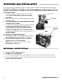
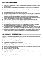
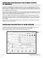
1
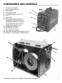
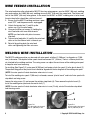
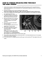
Eastwood Mig175 with Spool Gun
Assembly and Operating Instructions
Part #12012
Carefully read this operation manual prior to using, installing and maintaining your welder
to prevent damage such as fire and electric shock from occurring.
Please keep this manual for your future reference!
SPECIFICATIONS
Rated Electrical Input ............... 210-240 VAC; 50-60Hz; 22AMP
Max Voltage at No Load ........... 20 V DC
Rated Duty Cycle....................... 130A@30% duty cycle
Wire Feed Rate .......................... 4.9 Ft/min – 39.3 Ft/min
Wire Sizes .................................. 0.025”(0.6mm) – 0.030”(0.8mm) mig wire
0.030”(0.8mm) – 0.035” Flux core wire
Welding Wire Spool .................. 4” and 8” spool
Weight......................................... 62.0Lbs (24.5kg)
Overall Dimensions ................... 24.4 (620mm) x 12.6” (320mm) x 16.9 (430mm)
SAVE THIS MANUAL
You will need this manual for its safety warnings and precautions, assembly instructions, operating
and maintenance procedures, parts list and diagram. Keep your invoice with this manual. Keep this
manual and invoice in a safe and dry place for your future reference.
2
© Copyright 2010 Easthill Group, Inc.
SAFETY INFORMATION
ARC WELDING CAN BE DANGEROUS.
THIS WELDING MACHINE MUST BE CONNECTED TO POWER SOURCE IN ACCORDANCE WITH
APPLIANCE ELECTRICAL CODES.
• The plug is a NEMA 6-50P plug rated at 220VAC 50amp
• Wire selection: Use E70S for mild steel
Use E316 for stainless steel
Use E4043 for aluminum
DISCONNECT FROM POWER SOURCE BEFORE ASSEMBLING, DISASSEMBLY OR MAINTENANCE
OF THE TORCH, CONTACT TIP OR CHANGING WIRE SPOOLS.
FOR SAFETY TURN OFF AND UNPLUG MACHINE WHEN INSTALLING NEW WIRE SPOOL,
ADJUSTING WIRE TENSION ROLLER OR REPLACING CONTACT TIP.
THE GAS NOZZLE MUST ALWAYS BE INSTALLED WHEN WELDING-DO NOT WELD WITHOUT THE
GAS NOZZLE IN PLACE. THE CONTACT TIP IS ELECTRICALLY “HOT” AND IF IT CONTACTS THE
GROUNDED WORK PIECE IT WILL CAUSE DAMAGE.
ALL INSTALLATION, MAINTENANCE, REPAIR OPERATION OF THIS EQUIPMENT SHOULD BE PREFORMED BY QUALIFIED INDIVIDUALS IN ACCORDANCE WITH NATIONAL, STATE AND LOCAL CODES.
ELECTRIC SHOCK CAN KILL! Improper use of an electric welder can cause electric shock, injury
and death! Read all precautions described in this manual to reduce the possibility of electric shock.
The MIG175 power switch is to be in the OFF (“0”) position when installing the work cable and gun and
while plugging in the power cord.
Always wear dry, protective clothing and leather welding gloves and insulated footwear.
Always operate the welder in a clean, dry, well ventilated area. Do not operate the welder in humid, wet,
rainy or poorly ventilated areas.
Be sure that the work piece is properly supported and grounded prior to beginning an electric welding
operation.
The electrode and work (or ground) circuits are electrically “hot” when the welder is on. Do not touch
these “hot” parts with your bare skin or clothing.
DO NOT TOUCH THE CONTACT TIP WITH THE UNIT TURNED “ON”. Turn the unit off before changing tips or cleaning the nozzle.
Always attach the ground clamp to the piece to be welded and as close to the weld area as possible.
This will give the least resistance and best weld.
To order parts and supplies, call 1-800-345-1178 or visit www.eastwood.com
3
SAFETY INFORMATION
FUMES AND WELDING GASES CAN BE DANGEROUS.
Do not breathe fumes that are produced by the welding operation. These fumes are dangerous. Keep
your head and face out of welding fumes. Shielding gases used for welding can displace air and cause
injury or death. Always work in a properly ventilated area.
WELDING SPARKS CAN CAUSE FIRE OR EXPLOSION.
Do not operate electric arc welder in areas where flammable or explosive vapors are present. Always keep
a fire extinguisher nearby while welding. Use welding blankets to protect painted surfaces, dash boards
engines, etc.
ARC RAYS CAN BURN.
Use a shield with the proper filter ( a minimum of #11) to protect your eyes from sparks and the rays of the
arc when welding or when observing open arc welding. Use suitable clothing made from durable flame-resistant leather material to protect your skin. Protect nearby individuals with a non-flammable barrier.
HOT METAL WILL BURN.
Electric welding operations cause sparks and heats metal to temperatures that will cause severe burns!
Use protective gloves and clothing when performing any welding operations. Always wear long pants,
long-sleeved shirts and leather welding gloves. Make sure that all persons in the welding area are protected from heat, sparks and ultraviolet rays. Use additional face shields and flame resistant barriers as
needed. Never touch work piece until it has completely cooled.
ELECTROMAGNETIC FIELDS MAY BE DANGEROUS.
The electromagnetic field that is generated during arc welding may interfere with various electrical and
electronic devices such as cardiac pacemakers. Anyone using such devices should consult with their
physician prior to performing any electric welding operations. Exposure to electromagnetic fields while
welding may have other health effects which are not known.
UNPACKING
When unpacking, check to make sure all the parts listed below are included.
•
•
•
•
•
•
•
•
•
4
Mig 175 Unit
Spool Gun
Torch Gun Cable Assembly
Ground Cable Assembly
Gas Flow Regulator
Gas Flow Regulator Hose
Hand-Held Shield
Wire Brush
2 lb. Spool of 0.023” Mig Wire
© Copyright 2010 Easthill Group, Inc.
COMPONENTS AND CONTROLS
1.
2.
3.
4.
5.
6.
7.
8.
9.
10.
11.
12.
13.
Gun torch access hole.
Opening for ground cable.
4
Power switch.
Potentiometer knob.
3
Wire speed, feed rate adjust knob.
Latch.
Power Cord.
5
Reset overload protective device –
the protector will cut off the circuit if
the welding machine is in excess of
1
the maximum load, after which the
switch must be manually reset.
Shielding gas inlet fitting.
2
Wire feed tension roller.
Wire spool mount spindle.
Wing screw to fasten the welding torch cable.
Positive (+) and negative (-) output terminals.
FIG. B
6
13
8
7
12
9
10
11
To order parts and supplies, call 1-800-345-1178 or visit www.eastwood.com
5
WIRE FEEDER INSTALLATION
The wire feed drive roller attached to MIG175 has two wire grooves, one for 0.023” (0.6 mm) welding
wire and another for 0.030 (0.8 mm) welding wire or 0.035” (0.9 mm) flux-cored wire. The factory default is the 0.023” (0.6 mm) wire groove. In the event that 0.030” or 0.035” welding wire is to be used,
the wire feed roller should be switched around .
FIG. C
1. Ensure that the MIG175 welding machine is pow2
ered “OFF” and the power cord is unplugged.
2. Unlock the tension bar (1) and lift up the
3
rocker arm (2) of the wire feeder.
3. Unscrew the Allen set screws (3) holding the
wire Feed roller with inner Allen wrench.
NOTE: turn feed roller with pliers to access
1
allen bolt.
4. Take out wire feed roller (4) and flip the wire feed
4
roller so that the 0.8mm mark is towards you.
5. Reinstall by putting back the wire feed
roller and tightening the Allen set screw.
WELDING WIRE INSTALLATION
The MIG175 welding machine can be used with wire spools of either 8” (200 mm ) in diameter or 4”(100
mm) in diameter. The depth of either spool should not exceed 2.2” (56 mm). There is a 50mm plastic barrel attached to the welding machine. The swing screw can adjust the resistance of the welding wire spool
to keep the wire from loosening.
For installing (See Figure D-2) a wire spool 8”(200 mm) in diameter, attach the spool (1) to the plastic barrel (2).
The position-fixing pole of the plastic barrel should be aligned with the locating hole of the welding wire spool.
(NOTE: the wire spool will rotate clockwise when wire is in use.)
To install the welding wire spool 4”(100 mm) in diameter, remove “plastic barrel” and install wire spool with
stop block and wing screw.
Loosen the wing screw (5) and remove the rotation-stop block (6). Then remove the plastic barrel (2).
Install the welding wire spool onto the metal shaft (7).
(NOTE: the wire spool will rotate clockwise when wire is in use). Finally, reinstall the rotation-stop block
and the wing screw.
FIG. D-1
FIG. D-2
3
1
2
Figure D-1
Use the welder wire board
with 8” (200 mm) in dia.
6
Figure D-2
Use the welder wire board
with 4” (100 mm) in dia.
© Copyright 2010 Easthill Group, Inc.
HOW TO THREAD WELDING WIRE THROUGH
THE WIRE FEEDER
1.
2.
3.
4.
5.
6.
7.
8.
9.
10.
Unlock the tension bar (1) on the wire tensioner and lift up the rocker arm (2). Insure that the wire
drive wheel is appropriate to the welding wire size, see above describing the installation to wire feed
roller installation.
Pull out the welding wire (3) from the welding wire spool carefully.
NOTE: Do not let go of the wire prior to step 5 or the entire spool will unravel and be useless.
Cut off the small piece of the curved segment at the front of welding wire and straighten the welding
wire approximately 3.0” long.
Thread the welding wire through the
FIG. E
guide pipe (4) and over the wire feed
roller (5) and into the torch hole (6).
2
Reattach the rocker arm (2) and reset
the presser bar (1) of the wire feeder
(now the welding wire can be fed
smoothly).
Remove the contact tip and nozzle
from the mig gun.
Turn on the machine and set the wire
speed about 1⁄2 on the scale.
With the gun pointed away from you
and others, depress the trigger to
begin feeding wire.
NOTE: Watch the drive roller to see if
6
5
4
3
1
any slipping is occurring between the
roller and the wire- if so turn the machine
off and tighten the tension wing nut 1⁄4 turn and test again.
You do not want too much tension on the tension roller as it will tend to deform the wire. Just enough
to feed the wire without slipping
Once wire the wire has emerged from the tip of the gun, turn the machine OFF and replace the tip and
nozzle.
To order parts and supplies, call 1-800-345-1178 or visit www.eastwood.com
7
SHIELDING GAS INSTALLATION
A compressed gas cylinder containing 75% Argon and 25% CO2 should be used when using the
MIG (GMAW - GAS Metal Arc Welding) on steel. Use pure argon when welding aluminum. The flow
regulator and supply hose is included with your welder. Compressed gas can be obtained from your
local welding suppler.
Valve
1. Attach the compressed gas cylinder with a chain to
a wall or other secure object, to prevent the cylinder
from falling.
Flow
2. After securing the tank, remove the cylinder cap if your
regulator
cylinder has one.
3. Install flow regulator to the supply valve on the cylinder
and tighten it with a wrench.
4. Install one end of the gas supply hose into the outlet of
the flow regulator and tighten. Connect the other
Hose feeds
end of the hose to the gas inlet located at the rear of
to protective
gas input
the MIG175 welding machine (The connector nipple
FIG. F
5/8-18 adapts to CGA-032). Ensure that the hose is not
twisted or knotted.
5. Slowly turn on the gas cylinder valve.
6. Depress gun trigger switch and adjust the flow regulator to 25-30 cubic ft per hour (CFH), (12-14 l/min).
7. Shut off the bottle valve when not in use. Power off
your unit when you are done welding.
NOTE: Always keep the valve of the gas cylinder
closed when it is not in use.
WELDING OPERATIONS
1.
2.
3.
4.
8
Plug in the MIG175 Welding Machine.
Straighten out the welding torch.
Turn ON the unit and depress the gun trigger. Feed wire and cut 1⁄4” from the end of the nozzle.
Place the ground clamp as close to the welding zone as possible and remove any paint corrosion,
grease and oils before welding.
© Copyright 2010 Easthill Group, Inc.
WELDING PROCESS
1. Please refer to “Welding Label” in the unit and select proper setting based on the variety of metals
and their thickness.
2. Adjust output polarity according to the welding wire and to ensure whether or not the protective
gases are needed.
3. Connect the ground clamp to work pieces that are to be welded. This connection should be good
and secure.
4. Your welding torch should have clear access to the work piece
5. Wearing your welding helmet, gloves and long sleeve shirt and pants, press the trigger of the welding gun
and begin to weld. Keep the nozzle of the welding torch approximately 1/4” away from the work piece.
6. Use a “Push” technique which means you will be holding the gun in your right hand with the nozzle and gun tilted back about 10-20 degrees and pushing the gun or moving from right to left.
7. Once you depress the trigger the wire will arc and you will notice a molten puddle from. You want
to “move” this puddle to the left following the seam or areas to be welded.
8. If you “burn through” the material you are moving too slowly or you heat setting is too high.
9. The sound of bacon frying is what you are after. Start with the initial setting on the chart and increase or decrease wire speed to obtain the best weld
10. Release the trigger of the welding torch to stop welding
11. After welding, close valve of the gas bottle (if gas is used) and then press trigger of the welding
torch to release any gasses left in the hose. Finally, power off the welding machine
12. If you’re welding patch panels or quarter panels on use the “stitch” type method. Depress the trigger momentarily to form a small puddle or single bead. Then depress again to form another bead
aside of the first. Continue until you have 4 or 5 small beads connected about 1⁄2-3/4” in length.
13. Move to the other end of the panel and repeat the process. Now go to the middle and repeat. Continue this process moving to different areas of the panel to eliminate heat warping the material.
SPOOL GUN OPERATION
Your MIG175 can operate a hand-held spool gun. This will allow you weld both Aluminum and Steel.
NOTE: for use on steel 18ga - 1/4”; aluminum 1/8” plate or thicker.
1.
2.
3.
4.
5.
6.
7.
8.
9.
10.
Turn the power off and remove plug from AC outlet
Change the internal switch from MIG to Spool Gun
Plug spool gun into outlet on the front panel of the unit.
Install 4” roll of steel or aluminum (4043) wire
NOTE: Spool gun with Mig will only weld aluminum plate 1/8” and thicker
Use 100% pure Argon shielding gas
Clean the aluminum and weld area with a new stainless steel brush to remove all oxides from surface
Use a “push” gun movement technique
Keep the contact tip 3⁄4” from work piece
Set voltage setting to E/F and wire speed to 5 for 1/8” thick material
Set voltage setting to H/I and wire speed to 8/9 for materials over 1/8”
NOTE: these are initial start settings you will have to fine tune to meet materials thicknesses and welding techniques.
To order parts and supplies, call 1-800-345-1178 or visit www.eastwood.com
9
OVERLOAD PROTECTION FOR POWER SUPPLY
TO WELDING
Your MIG175 is equipped with a temperature controller as well as an overload breaker. These two
protection devices will protect the welding machine whenever the output exceeds the maximum output. If the output is exceeded, the unit will not supply voltage and the wire feeder will shut down (the
fan will continue to run to cool the unit).
If the shut-down resulted from output overload, the circuit breaker button will extend out if it has been
tripped. The circuit breaker must be reset manually. Before resetting the circuit breaker button, wait
several minutes to allow the welding machine to cool down.
If there is no voltage and circuit breaker was not tripped, the internal thermal protector may have
shut off the machine until it cools to a reasonable operating temperature. This is an automatic function and does not require the user to manually reset anything. The fan will continue to run while the
unit is cooling.
If the unit is still “ON” but neither the output nor fan is working, either an overload fuse or a power
supply circuit fuse has been blown.
OVERLOAD PROTECTION TO WIRE FEEDER
The MIG175 model has two automatic circuits to protect motor of the wire feeder, if there is fault
occurred to the motor, the circuit will power off wire feeder as well as the output.
When the trigger is released again, the circuit will be automatically reset.
FIG. G
10
© Copyright 2010 Easthill Group, Inc.
NOTES
Visit Eastwood.com
to see our welding videos!
To order parts and supplies, call 1-800-345-1178 or visit www.eastwood.com
11
NOTES
If you have any questions about the use of this product, please contact
The Eastwood Technical Assistance Service Department:
1-866-759-2131 email: [email protected]
The Eastwood Company
263 Shoemaker Road, Pottstown, PA 19464, USA
US and Canada: 1-800-345-1178
Outside US: 610-718-8335
fax: 610-323-6268
www.eastwood.com
Instruction Manual #12012Q - Rev. 12/09