1
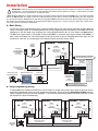
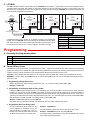
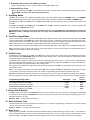
TECHNICAL
Practice
TELECOM SOLUTIONS
FOR THE
Practice
ES-1
Stand Alone Door
Controller Entry System
2 1 S T C E N T U RY
February 15, 2005
Add Keyless Entry and/or Card Reader Entry
for a Single Door with Up to 250 Users
The ES-1 is a door controller designed to operate a
door strike or magnetic lock upon receiving a valid
card read and/or keyless entry code from Wiegand
devices. One ES-1, one or two Wiegand devices and
a door strike or magnetic lock of your choice is
required for each entry point.
The Wiegand device used may be the Viking model
HID-1 Proximity Card Reader and/or the Viking
model HID-2 Wiegand Output Keypad or any other
card reader, RF transmitter or digital keypad that outputs the 26 bit Wiegand format. If two Wiegand
devices are used, one can be placed on each side of
a doorway to control access in both directions (entry and exit). Up to 250 valid Wiegand codes
can be programmed into the ES-1.
Other programmable parameters, like relay activation, mode (normal, off, or open) and facility
codes are also stored in non-volatile memory. All programming is done with a local touch tone
phone. Up to three ES-1s can be programmed simultaneously if they will be sharing all the
same programming codes and parameters. Entry logging is possible with the ES-1’s log bus
data output.
Phone...715.386.8861
Features
• Up to 250 tenants
• Program and control with a Touch Tone phone
• Use with any 26 bit Wiegand device
• Supports 1 entry point
• Compatible with Viking models HID-1 and HID-2
• Non-volatile memory (no batteries required)
• LOG BUS data output for logging entry events
• Card plus keypad mode for highest security
• One time codes for visitors
• Bi-directional (entry and exit) control
[email protected]
h t t p : / / w w w. v i k i n g e l e c t r o n i c s . c o m
Applications
• Business entrances
• High rise apartment buildings
• Condos
• Senior citizen buildings
• Assisted care centers
• Retirement homes
• Gated communities
Specifications
Power: 120V AC/12V DC 500mA, UL listed adapter provided or
use any 12-24V AC or DC source @ 100mA (designed to share
power with the door strike’s power supply)
Dimensions: 133mm x 89mm x 44mm (5.25” x 3.5” x 1.75”)
Shipping Weight: 1.3 kg (3 lbs)
Environmental: 0° C to 32° C (32° F to 90° F) with 5% to 95%
non-condensing humidity
Relay Contact Ratings: 5A @ 30V DC/250V AC maximum
Maximum Wiegand Length: 732m (2000 ft) - 24 AWG
Maximum LOG BUS Length: 1610m (5280 ft - 1 mile), 24 AWG
Connections: 11 screw terminals, (1) RJ-11 telco jack
IF YOU HAVE A PROBLEM WITH A VIKING PRODUCT, PLEASE CONTACT: VIKING TECHNICAL SUPPORT AT (715) 386-8666
Our Technical Support Department is available for assistance Monday 8am-4pm and Tuesday-Friday 8am - 5pm central time. So that we can give you better service, before you call please:
1. Know the model number, the serial number and what software version you have (see serial label).
2. Have your Technical Practice in front of you.
3. It is best if you are on site.
RETURNING PRODUCT FOR REPAIR
RETURNING PRODUCT FOR EXCHANGE
The following procedure is for equipment that needs repair:
1. Customer must contact Viking's Technical Support Department at 715-386-8666 to obtain a Return Authorization (RA)
number. The customer MUST have a complete description of the problem, with all pertinent information regarding the
defect, such as options set, conditions, symptoms, methods to duplicate problem, frequency of failure, etc.
2. Packing: Return equipment in original box or in proper packing so that damage will not occur while in transit. Static
sensitive equipment such as a circuit board should be in an anti-static bag, sandwiched between foam and individually boxed. All equipment should be wrapped to avoid packing material lodging in or sticking to the equipment. Include
ALL parts of the equipment. C.O.D. or freight collect shipments cannot be accepted. Ship cartons prepaid to:
Viking Electronics, 1531 Industrial Street, Hudson, WI 54016
3. Return shipping address: Be sure to include your return shipping address inside the box. We cannot ship to a PO Box.
4. RA number on carton: In large printing, write the R.A. number on the outside of each carton being returned.
The following procedure is for equipment that has failed out-of-box (within 10 days of purchase):
1. Customer must contact Viking’s Technical Support at 715-386-8666 to determine possible causes for the problem. The
customer MUST be able to step through recommended tests for diagnosis.
2. If the Technical Support Product Specialist determines that the equipment is defective based on the customer's input
and troubleshooting, a Return Authorization (R.A.) number will be issued. This number is valid for fourteen (14)
calendar days from the date of issue.
3. After obtaining the R.A. number, return the approved equipment to your distributor, referencing the R.A. number. Your
distributor will then replace the product over the counter at no charge. The distributor will then return the product to
Viking using the same R.A. number.
4. The distributor will NOT exchange this product without first obtaining the R.A. number from you. If you haven't
followed the steps listed in 1, 2 and 3, be aware that you will have to pay a restocking charge.
WARRANTY
Viking warrants its products to be free from defects in the workmanship or materials, under normal use and service, for a period of one year from the date of purchase from any authorized Viking distributor or 18 months from the date manufactured, which ever is greater. If at any time during the warranty period, the product is deemed defective or malfunctions, return the product to Viking Electronics, Inc., 1531 Industrial Street, Hudson, WI., 54016. Customer must contact Viking's
Technical Support Department at 715-386-8666 to obtain a Return Authorization (R.A.) number.
This warranty does not cover any damage to the product due to lightning, over voltage, under voltage, accident, misuse, abuse, negligence or any damage caused by use of the product by the purchaser or others.
Vikings sole responsibility shall be to repair or replace (at Viking's option) the material within the terms stated above. VIKING SHALL NOT BE LIABLE FOR ANY LOSS OR DAMAGE OF ANY KIND INCLUDING INCIDENTAL OR CONSEQUENTIAL DAMAGES RESULTING DIRECTLY OR INDIRECTLY FROM ANY BREACH OF ANY WARRANTY EXPRESSED OR IMPLIED, OR FOR ANY OTHER FAILURE OF THIS PRODUCT. Some states do not allow the exclusion or limitation of incidental or consequential damages, so this limitation may not apply to you.
THIS WARRANTY IS IN LIEU OF ALL OTHER WARRANTIES, EXPRESSED OR IMPLIED, INCLUDING THE WARRANTIES OF MERCHANTABILITY AND FITNESS FOR A PARTICULAR PURPOSE, WHICH ARE HEREBY EXCLUDED
BEYOND THE ONE YEAR DURATION OF THIS WARRANTY. Some states do not allow limitation on how long an implied warranty lasts, so the above limitation may not apply to you.
Definitions
26 Bit Wiegand Format: The industry standard data output of access control card readers.
Bi-Directional Access: Two Wiegand devices can be wired in parallel to one ES-1 to control access in both
directions at a single entry point. Simply place one card reader on each side of the door or gate. When either
one detects a valid code, the ES-1 will strike the door. Data logging will not be able to distinguish the direction
of the access. If that is a requirement, two separate ES-1s will need to be installed, so each one can log separate access events from each side of the door.
Card Plus Keypad Mode: This is a higher security mode in which a valid card + a valid keypad entry is required
to gain access.
Entry Code: The number that when it matches either a Keyless Entry or a Proxy Card number, allows access.
Each tenant may have their own unique Entry Code that is easily changed or removed when a tenant moves
out.
Entry Point: A door or gate allowing access into a secure or controlled area.
Facility Code: A 3-digit number that each proxy card contains in order to provide greater security. Usually the
cards used at a given building all have the same facility code.
Keyless Entry: A way for tenants to let themselves in, by entering their entry code on a keypad.
LOG BUS: A two wire data bus that can be wired in parallel with additional ES-1 log busses. Data is sent as
1200 baud ASCII characters at TTL levels (0-5 Volt). Any RS-232 port designed to receive TTL levels can receive
log bus data directly on the “Receive Data” and “Signal Ground” pins.
Memory Location: The number used when programming, that stores the location of an entry code.
One Time Code: An entry code that can only be used once - this feature is handy for visitors. Once the code
is used the ES-1 forgets it.
Proxy Card: A credit size card that identifies itself when within close proximity of a reader. Card “swiping” is not
necessary. The card contains a 3 digit Facility Code, a 5 digit Internal Card number and a 5 digit External Printed
number, that may or may not match the Internal number.
Proxy Card Reader: A device used to read the data from a Proxy Card when its held within a few inches of the
reader.
Installation
!
IMPORTANT: Electronic devices are susceptible to lightning and power station electrical surges from both the AC outlet and the
telephone line. It is recommended that a surge protector be installed to protect against such surges. Contact Panamax at (800)
472-5555 or Electronic Specialists Inc. at (800) 225-4876.
* Note: Maximum Wiegand run length is 2000 feet using 24 gauge wire when using the Viking Model HID-1 proxy card reader, and 4000
feet for the HID-2 keypad. Run length is reduced in half if two share the same wire run from the same ES-1 entry point. Run length will
also be reduced if using a Wiegand device other than the Viking Model HID-1, that requires more than 35mA average operating current.
Run lengths can be doubled by doubling up on the BLACK and RED 24 gauge wire, or using 21 gauge (or larger) wire. Certain electrically noisy locations might require shielded wire.
A. Basic Wiring
A basic door access controlled entry point is wired as shown below. The relay can be connected as either Normally
Open, or Normally Closed. All 26-bit Wiegand devices are fully supported (power and data) from the ES-1 and can be
installed up to 500 feet away using 24 gauge wire. Viking Wiegand devices can run even further (see Note above).
The ES-1 can support either a card reader (Viking model HID-1) or a keyless entry keypad (Viking model HID-2), or
both. If both are installed, the “Card Plus Keypad” mode can be used. If any two Wiegand devices are used, one can
be placed on each side of a doorway/gate for bi-directional (entry and exit) access control.
VIKING ©
12V DC
Adapter
Included
MODEL ES-1
VIKING
ELECTRONICS
HUDSON, WI 54016
POWER 12 VDC
STAND-ALONE
DOOR CONTROLLER
ENTRY SYSTEM
ENTRY POINT
?
WHT
BLK
or
RED
WIEGAND
DEVICE
GANG
LOG PROG
BUS COMM
GRN
Doorstrike
Power Supply
5A@30VDC/250VAC
maximum
(not included)
Need More Information on the HID-2?
Call (715) 386-4345 and select 199.
Viking HID-2
Keypad
(not included)
PROGRAM
PHONE
1219m (4000 ft) maximum
Doorstrike/Magnetic Lock
(not included)
(Power typically not
required for gate
controllers.)
Remote Touch Tone
Programming Phone
RAD-1 Remote Access
Device (not included)
Touch Tone
Programming Phone
609m (2000 ft) maximum
and/or
Viking HID-1
Proximity Card
Reader
(not included)
or
?
Need More Information on the HID-1?
Call (715) 386-4345 and select 197.
B. Gang Programming Wiring
If multiply ES-1s are installed to handle door access control for multiple entry points, two or three of them can be programmed simultaneously if they are to be programmed identically. Do this by wiring GANG PROG COMM screw terminals 1 together, and screw terminals 2 together. The touch tone programming phone connected to any one of them
will program all of them simultaneously.
Touch Tone
Programming
Phone
1
2
PROGRAM
PHONE
609m (2000 ft) maximum
with 24 gauge wire
1
2
ENTRY POINT
PROGRAM
PHONE
609m (2000 ft) maximum
with 24 gauge wire
1
2
WIEGAND
DEVICE
WHT
WHT
GANG
LOG PROG
BUS COMM
BLK
WIEGAND
DEVICE
STAND-ALONE
DOOR CONTROLLER
ENTRY SYSTEM
RED
POWER 12 VDC
ENTRY POINT
GANG
LOG PROG
BUS COMM
WHT
BLK
RED
WIEGAND
DEVICE
STAND-ALONE
DOOR CONTROLLER
ENTRY SYSTEM
BLK
ENTRY POINT
MODEL ES-1
VIKING
ELECTRONICS
HUDSON, WI 54016
RED
STAND-ALONE
DOOR CONTROLLER
ENTRY SYSTEM
GANG
LOG PROG
BUS COMM
PROGRAM
PHONE
POWER 12 VDC
VIKING
ELECTRONICS
HUDSON, WI 54016
GRN
POWER 12 VDC
VIKING
ELECTRONICS
HUDSON, WI 54016
VIKING ©
MODEL ES-1
GRN
VIKING ©
MODEL ES-1
GRN
VIKING ©
C. LOG BUS
The ES-1 transmits 1200 baud ASCII data from the LOG BUS screw terminals. Log Bus data is sent each time Wiegand data is
received from the entry point, and includes: an entry point ID number, if the entry was valid, non-valid, or off, the facility code, and
the card number (or keypad entry code). The Log Bus can be daisy-chained by wiring the LOG BUS screw terminals L together and
screw terminals H together as shown below.
L
ENTRY POINT
WHT
BLK
WIEGAND
DEVICE
RED
GANG
LOG PROG
BUS COMM
GRN
WIEGAND
DEVICE
PROGRAM
PHONE
H
STAND-ALONE
DOOR CONTROLLER
ENTRY SYSTEM
WHT
GANG
LOG PROG
BUS COMM
WHT
BLK
RED
POWER 12 VDC
ENTRY POINT
WIEGAND
DEVICE
PROGRAM
PHONE
L
Yellow
(Signal Ground)
STAND-ALONE
DOOR CONTROLLER
ENTRY SYSTEM
BLK
ENTRY POINT
MODEL ES-1
VIKING
ELECTRONICS
HUDSON, WI 54016
RED
POWER 12 VDC
STAND-ALONE
DOOR CONTROLLER
ENTRY SYSTEM
GANG
LOG PROG
BUS COMM
H
Brown
(Receive Data)
VIKING ©
MODEL ES-1
VIKING
ELECTRONICS
HUDSON, WI 54016
GRN
Pin 5
(Signal
Ground)
POWER 12 VDC
Pin 2
(Receive
Data)
VIKING ©
MODEL ES-1
VIKING
ELECTRONICS
HUDSON, WI 54016
GRN
VIKING ©
DB-9
(not included)
PROGRAM
PHONE
H
L
H
L
24 gauge wire
1610m (5280 ft - 1 mile)
maximum run length
Communication Software Configuration
If the RS-232 input of a PC, printer, etc. is capable of receiving TTL level RS-232
signals, then the LOG BUS can be wired directly into the RS-232 “Receive Data”
and “Signal Ground” pins to receive ASCII data. Windows “Hyper-Terminal” can be
used to receive the data on a PC. Use the settings in the chart at the right:
Com
Your serial port (1-4)
Baud Rate
1200
Data Bits
8
Stop Bits
1
Parity
none
Flow Control
none
Programming
A. Accessing the Programming Mode
Step 1. Connect a touch tone phone to the PROGRAM PHONE jack.
Step 2. Come off hook. A double beep will indicate that programming has been entered.
Step 3. Program as shown in section B - I.
Step 4. To exit programming, simply hang up the phone.
B. Tenant’s Entry Codes
The ES-1 can be programmed with up to 250 tenant entry codes. A tenant can activate the door strike, keyless, from a Wiegand
keypad or by using a proxy card with its 5 digit card number programmed as the entry code. When a given tenant moves out of the
complex, the entry code for that tenant may be cleared without affecting any other tenant’s entry code.
Important: 26-bit Wiegand data limits the entry code range from 00001 to 65535. Entry codes larger than 65535 will not work.
WARNING: If using a Viking model HID-2 keypad, do not program the ES-1 to accept entry code 65535 because that is the keypad’s error code.
1. Programming a Single Entry Code
While in programming, enter the tenant’s 5 digit entry code + “#” + memory location number (001 - 250).
Example: 12345 # 001
2. Programming a Continuous Bank of Entry Codes
If using the HID-2 keypad for keyless entry, it is an advantage, from a security standpoint, to have the entry codes all random
numbers. On the contrary, if using the HID-1 card reader, proximity cards are typically purchased as a continuous bank of
incrementing numbers. If this is the case, a large block of incrementing numbers can be programmed all at once. While in programming, enter the first (lowest value) 5 digit card number entry code + “#” + the starting memory location number (001 - 249).
After two beeps are heard, enter #✱ + the ending memory location (002 - 250).
Example: 10300 # 001 (wait for two beeps) #✱ 150
This will fill memory positions 001 through 150 sequentially with entry codes 10300 through 10450.
3. Programming One Time Entry Codes
An entry code that can only be used once, and
is then forgotten by the ES-1, can be programmed similar to a single entry code or a
bank of entry codes as shown above. An extra
“✱” before the “#” makes it a one time code.
Example: 12345 ✱# 001
This will fill memory position 001 with one time entry code 12345.
Example: 10300 ✱# 001 (wait for two beeps) #✱ 150
This will fill memory positions 001 through 150 sequentially with one time
entry codes 10300 through 10450.
4. Deleting the Entry Code for One Memory Location
While in programming, enter “#” + memory location number (001 - 250) to clear.
5. Deleting All Entry Codes
While in programming, enter “###”. This will clear all entry codes, all facility codes, and set all programming to factory settings.
! CAUTION: All entry codes will be permanently erased.
C. Operating Modes
The ES-1 can be set into one of 3 different operating modes. The factory default setting is the NORMAL mode. In the NORMAL
mode, the ES-1 strikes the door when a proper card or keyless code is entered. Enter ✱1 to put the ES-1 in NORMAL mode.
Enter ✱0 to put the ES-1 in the OFF mode. In the OFF mode, the ES-1 will not strike the door, even if a proper card or keyless code
is entered.
Enter ✱2 to put the ES-1 in the OPEN mode. In the OPEN mode, the ES-1 continuously strikes the door. No card or keyless code
is needed, and no LOG BUS data is sent.
! CAUTION: Some strikes are designed for intermittent operation only. The OPEN mode should NOT be used with these
intermittent strikes, or damage to the strike may occur. Only use the OPEN mode with strikes designed for continuous
operation.
D. Card Plus Keypad Mode
This is a mode in which a valid card, plus a valid keypad entry is required to gain access. Both a card reader (Viking model HID1) and a keypad (Viking model HID-2) are required at the entry entry point. A higher level of security is achieved because acquiring someone’s card is not enough to gain access. The number to be entered on the keypad must match the 5-digit internal card
number. Because of this, it is important the actual 5-digit card number is not printed on the card itself.
While in programming, enter “✱7” to put the ES-1 into the Card Plus Keypad mode, or enter “✱8” to remove the ES-1 from this mode.
Note: The cards can have a facility code of 001 to 254, but the keypad in use must have its facility code programmed to 255, so
the ES-1 knows one from the other (see section E).
E. Facility Codes
A Wiegand type card reader can be added to the ES-1 entry point for card access control. Twenty-six bit Wiegand access cards,
such as Viking’s model PROXCARD, identify themselves with an 8-digit number. The first three digits are considered the Facility
Code and the last five are the card number.
The ES-1 shares the 5 digit entry code memory location for both keypad entry and card entry. In other words, the 5-digit card number is to be programmed as the tenant’s entry code. Unless facility codes are programmed, the ES-1 will only need to match the 5digit card number with any programmed entry code to allow access.
For a higher level of security the 3-digit Facility Code should be programmed. Each ES-1 can be programmed to accept up to 4 different Facility Codes.
Note: If all 4 Facility Code locations are programmed to “000” (factory setting), the ES-1 will disregard the Facility Code all together, thus making access entry based only on the card number (or keypad entry) match with the programmed entry code.
Important: 26-bit Wiegand data limits the facility code range from 001 to 255. A facility code larger than 255 will not be accepted.
When in programming, enter the 3-digit Facility Code of the access cards being used, then “#” and the memory locations as follows:
Memory
Enter Digits
- then Location
Programming Facility Codes
First Facility Code (factory set to 000) ........................................................................................
Second Facility Code (factory set to 000) ...................................................................................
Third Facility Code (factory set to 000) .......................................................................................
Fourth Facility Code (factory set to 000) .....................................................................................
3
3
3
3
digits
digits
digits
digits
+
+
+
+
#911
#912
#913
#914
F. Entry Point ID Number
The ES-1 outputs event data on the LOG BUS each time a card or keypad is used. An ID number can be programmed in each ES1 so that the device receiving the LOG BUS data knows which entry point the event came from. While in programming, enter a single digit ID number (1-9) + ##7.
Example: 6 ##7 = an Entry Point ID number of 6
G. Relay Activation Time
The relay activation time can be programmed in seconds from 01 - 99. When in programming, enter the time in seconds + ##3 (00
= 1/2 second, factory set to 5 seconds).
Example: 05 ##3 = a 5 second relay activation time
H. Beep Tones
While programming the ES-1, a double beep will be heard after entering a valid command or memory location. If an invalid command or number sequence is entered, it will be indicated by a triple beep. If an error is made, review the instructions and re-program that location. The ES-1 is capable of detecting hardware memory errors and will output 4 beeps if there is a problem.
I. Programming Features Quick Reference
Features
Enter Digits
- then -
Memory
Location
A single entry code .................................................................................................................................. 5 digits
+
#001-250
A single one time use entry code ............................................................................................................. 5 digits
+
✱#001-250
Continuous bank of entry codes ............................. Enter first code, then #, then first location, then #✱
+
last location
Clear one entry code ............................................................................................................................... (no digits)
+
#001-250
Off mode ................................................................................................................................................. ✱0
Normal mode (factory setting) ................................................................................................................. ✱1
Open mode (only use with compatible strikes, see Programming, section C) ....................................... ✱2
Touch Tone door strike activation ............................................................................................................ ✱6
Card plus keypad mode enabled ............................................................................................................. ✱7
Card plus keypad mode disabled (factory setting) ................................................................................... ✱8
Entry Point ID Number (factory set to 1) .................................................................................................. 1 digit
+
##7
Relay activation time (in seconds - factory set to 5 seconds) .................................................................. 2 digits
+
##3
Facility codes (all factory set to 000) ....................................................................................................... 3 digits
+
#911-914
Clear all entry codes and return all programming features back to factory settings ................................. ### (CAUTION: Erases ALL programming!)
Operation
A. Tenant Card Reader Entry
A Wiegand device, such as the Viking HID-1 Proximity Card Reader (not included), is fully supported (power and data) by the ES-1.
The ES-1 entry controller monitors the Wiegand devices for 26 bit Wiegand data. When a card is read, the data is compared against
the Facility Code (if used) and Entry Code data bases programmed in the ES-1, and access is granted if a match is found.
B. Tenant Keyless Entry
A Wiegand device, such as the Viking HID-2 Wiegand Keypad (not included), is fully supported (power and data) by the ES-1. The
ES-1 entry controller monitors the Wiegand devices for 26 bit Wiegand data. When a keyless code is entered on the keypad, the
data is compared against the Facility Code (if used) and Entry Code data base programmed in the ES-1, and access is granted if a
match is found.
C. Card Plus Keypad Entry
With both a Wiegand card reader and a Wiegand keypad wired to the same ES-1, either can be used to gain access. If the card plus
keypad mode is enabled, first the card must match a programmed facility code and entry code, then the same 5-digit entry code must
be entered on the keypad for access to be granted.
D. Touch Tone Commands
In addition to using a Touch Tone phone to program the ES-1, a few Touch Tone commands are also available as follows:
Touch Tone Command
Description
✱0
To put the ES-1 in the OFF mode (no cards or keyless entry numbers grant access).
✱1
To put the ES-1 back in the Normal operating mode.
✱2
To have the ES-1 continuously strike the door/gate (* Open mode), no LOG BUS data is sent.
✱6
To momentarily strike the ES-1, this allows someone within the building to allow a visitor in, even if
the ES-1 is in the Off mode, no LOG BUS data is sent.
* Note: Only use the Open mode with compatible strikes (see Programming, section C).
E. One Time Entry Codes
An entry code can be programmed for one time use. If this is the case, once the entry code has been used, it is instantly forgotten
by the ES-1. This feature allows visitors limited access.
Simulated LOG BUS Output
F. Data Logging
Each time either a card is read or a keypad entry has been received, the ES1 will transmit 1200 baud ASCII data out of its LOG BUS screw terminals.
Data sent includes: an entry point ID number (1-9), if the entry was valid (V),
non-valid (N) or valid but access was not granted because the ES-1 was in
the OFF mode (F), the 3-digit facility code, and the card number (or keypad
entry). An example of 3 different entry events is shown to the right. The ES1 outputs entry event data in real time, but does not time stamp.
1
2
1
Entry Point ID
Valid, Not-Valid,
or OFF
V
N
F
255
132
255
12345
06336
12345
Card Number
or Keypad Entry
Facility Code
Visit www.vikingelectronics.com to download free ENTRY LOGGER software. The software provides transaction logging for the
ES-1 and C-4000 Entry Controller systems. Compatible with any Windows based PC running Windows 95 or higher, the software
adds time and date stamps to each transaction, and allows user printing, record saving, and complete search capabilities.
Please use these charts to record the numbers programmed into the ES-1 (use pencil).
Security Code:
Memory Location
001
002
003
004
005
006
007
008
009
010
011
012
013
014
015
016
017
018
019
020
021
022
023
024
025
026
027
028
029
030
031
032
033
034
035
036
037
038
039
040
041
042
043
044
045
046
047
048
049
050
051
052
053
054
055
056
057
058
059
060
061
062
063
064
065
066
067
068
069
070
071
072
073
074
075
Relay Activation Code:
Tenant’s Name
Entry Code #
Memory Location
076
077
078
079
080
081
082
083
084
085
086
087
088
089
090
091
092
093
094
095
096
097
098
099
100
101
102
103
104
105
106
107
108
109
110
111
112
113
114
115
116
117
118
119
120
121
122
123
124
125
126
127
128
129
130
131
132
133
134
135
136
137
138
139
140
141
142
143
144
145
146
147
148
149
150
Tenant’s Name
Entry Code #
Memory Location
Tenant’s Name
Entry Code #
151
152
153
154
155
156
157
158
159
160
161
162
163
164
165
166
167
168
169
170
171
172
173
174
175
176
177
178
179
180
181
182
183
184
185
186
187
188
189
190
191
192
193
194
195
196
197
198
199
200
201
202
203
204
205
206
207
208
209
210
211
212
213
214
215
216
217
218
219
Memory Location
Tenant’s Name
Entry Code #
220
221
222
223
224
225
226
227
228
229
230
231
232
233
234
235
236
237
238
239
240
241
242
243
244
245
246
247
248
249
250
Access Card Facility Codes
Memory Location
Facility Code
911
912
913
914
ID Number
Memory Location
1-Digit ID Number
##7
Relay Activation Time
Memory Location
Time in Seconds
##3
Product Support Line...715.386.8666
Fax Back Line...715.386.4345
Due to the dynamic nature of the product design, the information contained in this document is subject to change without notice. Viking Electronics, and its affiliates and/or
subsidiaries assume no responsibility for errors and omissions contained in this information. Revisions of this document or new editions of it may be issued to incorporate
such changes.
Fax Back Doc 193
Printed in the U.S.A.
ZF301940 Rev A