1
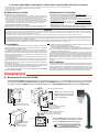
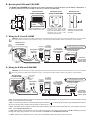
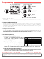
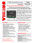
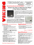
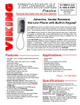
TECHNICAL
Practice
TELECOM SOLUTIONS
Practice
FOR THE
E-10, E-10-EWP,
E-20A, E-20A-EWP
Speaker Phones
May 9, 2006
2 1 S T C E N T U RY
Provide Convenient Handsfree Communication
The E-10 and E-20A are telephone line powered speaker phones designed
to provide two-way handsfree communication.
The E-10 and E-20A can be connected
directly to a C.O. line or analog
PABX/KSU station when used in conjunction with a Hot-Line Dialer or programmed ring down circuit. The E-10
and E-20A can also be used with
Viking’s DLE-200B ring down circuit.
When the “Call” button is pressed, the
E-10 or E-20A will come off-hook and
will remain off-hook until a CPC is detected or the pre-selected timeout
has elapsed, the unit will then automatically disconnect.
E-10/E-10-EWP
E-20A/E-20A-EWP
For outdoor or harsh environments, the E-10 and E-20A are available with Enhanced Weather Protection
(EWP). The E-10-EWP and E-20A-EWP feature rubber gaskets and boots, closed cell foam gasketing,
hand soldered silicon sealed connections, anti-corrosive gel filled tip and ring connectors, as well as urethane encapsulated circuit boards with internally sealed, field-adjustable trim POTS and DIP switches.
Phone...715.386.8861
Features
• Telephone line powered
• Weather resistant
• Optional Enhanced
Need More Information on EWP?
Weather Protection (EWP) ? Call (715) 386-4345 and select 859.
• Adjustable microphone and speaker volume
• Adjustable call time out, to limit prank calls and false
alarms (approximately 6 seconds - 5 minutes)
• Call timer ON/OFF switch
• Selectable auto-answer feature allows remote
monitoring
• Two way handsfree communication
• VOX (mic/speaker) switching speed selection
E-10/E-10-EWP Features
- Vandal resistant, black powder painted, aluminum
face plate with heavy duty metal call button and
mounting gasket
- Flush mountable using included plastic rough-in box
part # 259576
- Surface mountable with
Need More Information on VE-5x5?
? Call (715) 386-4345 and select 424.
an optional VE-5x5
E-20A/E-20A-EWP Features
- Light gray colored, impact resistant, U.V. stable,
plastic chassis
- Surface mountable only
Applications
•
•
•
•
Commercial, industrial and residential door security
Door or gate communication
Business delivery entrances
Use in conjunction with a Viking Hot-Line Dialer on
C.O. lines or analog PABX/KSU stations
• Use on any programmed ringdown circuit of an analog
PABX/KSU station
[email protected]
h t t p : / / w w w. v i k i n g e l e c t r o n i c s . c o m
Specifications
Power: Telephone line powered (18 VDC/20mA minimum)
E-10 Dimensions: Overall: 127mm x 127mm x 57.2mm (5” x 5”
x 2.25”), Rough-in box: 102mm x 102mm x 57mm (4” x 4” x 2.25”)
E-20A Dimensions: 140mm x 115mm x 38mm (5.5” x 4.5” x 1.5”)
Shipping Weights: E-10: 0.91 kg (2 lbs), E-20A: .75 kg (1.5 lbs)
Standard E-10/E-20A Environment: -26° C to 54° C (-15° F to
130° F) with 5% to 95% non-condensing humidity
E-10/E-20A-EWP Environment: -26° C to 54° C (-15° F to 130°
F) with up to 100% condensing humidity
Speaker Volume: Approximately 70db maximum @ 1m
Ring Voltage: 30V AC RMS minimum
CPC Disconnect Time: 300ms minimum
REN: 0.7A
Standard Connections: (1) 2-position terminal block
EWP Connections: (2) gel-filled butt connectors
IF YOU HAVE A PROBLEM WITH A VIKING PRODUCT, PLEASE CONTACT: VIKING TECHNICAL SUPPORT AT (715) 386-8666
Our Technical Support Department is available for assistance Monday 8am-4pm and Tuesday-Friday 8am - 5pm central time. So that we can give you better service, before you call please:
1. Know the model number, the serial number and what software version you have (see serial label).
2. Have your Technical Practice in front of you.
3. It is best if you are on site.
RETURNING PRODUCT FOR REPAIR
RETURNING PRODUCT FOR EXCHANGE
The following procedure is for equipment that needs repair:
1. Customer must contact Viking's Technical Support Department at 715-386-8666 to obtain a Return Authorization (RA)
number. The customer MUST have a complete description of the problem, with all pertinent information regarding the
defect, such as options set, conditions, symptoms, methods to duplicate problem, frequency of failure, etc.
2. Packing: Return equipment in original box or in proper packing so that damage will not occur while in transit. Static
sensitive equipment such as a circuit board should be in an anti-static bag, sandwiched between foam and individually boxed. All equipment should be wrapped to avoid packing material lodging in or sticking to the equipment. Include
ALL parts of the equipment. C.O.D. or freight collect shipments cannot be accepted. Ship cartons prepaid to:
Viking Electronics, 1531 Industrial Street, Hudson, WI 54016
3. Return shipping address: Be sure to include your return shipping address inside the box. We cannot ship to a PO Box.
4. RA number on carton: In large printing, write the R.A. number on the outside of each carton being returned.
The following procedure is for equipment that has failed out-of-box (within 10 days of purchase):
1. Customer must contact Viking’s Technical Support at 715-386-8666 to determine possible causes for the problem. The
customer MUST be able to step through recommended tests for diagnosis.
2. If the Technical Support Product Specialist determines that the equipment is defective based on the customer's input
and troubleshooting, a Return Authorization (R.A.) number will be issued. This number is valid for fourteen (14)
calendar days from the date of issue.
3. After obtaining the R.A. number, return the approved equipment to your distributor, referencing the R.A. number. Your
distributor will then replace the product over the counter at no charge. The distributor will then return the product to
Viking using the same R.A. number.
4. The distributor will NOT exchange this product without first obtaining the R.A. number from you. If you haven't
followed the steps listed in 1, 2 and 3, be aware that you will have to pay a restocking charge.
WARRANTY
Viking warrants its products to be free from defects in the workmanship or materials, under normal use and service, for a period of one year from the date of purchase from any authorized Viking distributor or 18 months from the date manufactured, which ever is greater. If at any time during the warranty period, the product is deemed defective or malfunctions, return the product to Viking Electronics, Inc., 1531 Industrial Street, Hudson, WI., 54016. Customer must contact Viking's
Technical Support Department at 715-386-8666 to obtain a Return Authorization (R.A.) number.
This warranty does not cover any damage to the product due to lightning, over voltage, under voltage, accident, misuse, abuse, negligence or any damage caused by use of the product by the purchaser or others.
Vikings sole responsibility shall be to repair or replace (at Viking's option) the material within the terms stated above. VIKING SHALL NOT BE LIABLE FOR ANY LOSS OR DAMAGE OF ANY KIND INCLUDING INCIDENTAL OR CONSEQUENTIAL DAMAGES RESULTING DIRECTLY OR INDIRECTLY FROM ANY BREACH OF ANY WARRANTY EXPRESSED OR IMPLIED, OR FOR ANY OTHER FAILURE OF THIS PRODUCT. Some states do not allow the exclusion or limitation of incidental or consequential damages, so this limitation may not apply to you.
THIS WARRANTY IS IN LIEU OF ALL OTHER WARRANTIES, EXPRESSED OR IMPLIED, INCLUDING THE WARRANTIES OF MERCHANTABILITY AND FITNESS FOR A PARTICULAR PURPOSE, WHICH ARE HEREBY EXCLUDED
BEYOND THE ONE YEAR DURATION OF THIS WARRANTY. Some states do not allow limitation on how long an implied warranty lasts, so the above limitation may not apply to you.
FCC REQUIREMENTS
If the trouble is causing harm to the telephone network, the telephone company may request you to remove
the equipment from the network until the problem is resolved.
The E-10/E-10-EWP/E-20A/E-20A-EWP phones use the USOC jack RJ11C.
It is recommended that the customer install an AC surge arrester in the AC outlet to which this device is connected. This is to avoid damaging the equipment caused by local lightning strikes and other electrical surges.
This equipment is Hearing-Aid Compatible (HAC).
The telephone Consumer Protection Act of 1991 makes it unlawful for any person to use a computer or other
electronic device, including fax machines, to send any message unless such message clearly contains in a margin at the top or bottom of each transmitted page or on the first page of the transmission, the date and time it is
sent and an identification of the business or other entity, or other individual sending the message and the telephone number of the sending machine or such business, other entity, or individual. (The telephone number provided may not be a 900 number or any other number for which charges exceed local or long-distance transmission charges.)
This equipment complies with Part 68 of the FCC rules. Located on the equipment is a label that contains,
among other information, the FCC registration number and ringer equivalence number (REN). If requested, this
information must be provided to the telephone company.
The REN is used to determine the quantity of devices which may be connected to the telephone line.
Excessive REN's on the telephone line may result in the devices not ringing in response to an incoming call. In
most, but not all areas, the sum of the REN's should not exceed five (5.0) To be certain of the number of devices
that may be connected to the line, as determined by the total REN's, contact the telephone company to determine the maximum REN for the calling area.
This equipment cannot be used on the telephone company-provided coin service. Connection to Party Line
Service is subject to State Tariffs.
If this equipment causes harm to the telephone network, the telephone company will notify you in advance
that temporary discontinuance of service may be required. If advance notice isn't practical, the telephone company will notify the customer as soon as possible. Also, you will be advised of your right to file a complaint with
the FCC if you believe it is necessary.
The telephone company may make changes in its facilities, equipment, operations, or procedures that could
affect the operation of the equipment. If this happens, the telephone company will provide advance notice in
order for you to make the necessary modifications in order to maintain uninterrupted service.
If trouble is experienced with this equipment, please contact: Viking Electronics, Inc., 1531 Industrial
Street, Hudson, WI 54016 (715) 386-8666
PART 15 LIMITATIONS
This equipment has been tested and found to comply with the limits for a Class A digital device, pursuant to Part
15 of the FCC Rules. These limits are designed to provide reasonable protection against harmful interference
when the equipment is operated in a commercial environment. This equipment generates, uses, and can radiate radio frequency energy and, if not installed and used in accordance with the instruction manual, may cause
harmful interference to radio communications. Operation of this equipment in a residential area is likely to cause
harmful interference in which case the user will be required to correct the interference at his own expense.
Installation
A. Mounting the E-10 and E-10-EWP
The E-10 and E-10-EWP are designed to be flush mounted to the included 4” x 4” x 2” deep plastic rough in box or surface mounted using optional Viking model VE-5x5. Note: The E-10 and E-10-EWP will NOT mount to a standard double gang box. The plastic rough in box (part # 259576) may be purchased separately. Go to www.vikingelectronics.com and click on “Spare Parts”.
2.1”
Front View of Plastic
Rough-In Box (included)
* 1/8" thick foam gasket (included)
4.0"
Wall Stud
* Note: Peel off paper liner and
adhere gasket to the back of the
faceplate, centering it over the four
corner mounting holes.
E-10A shown with
Viking Model
VE-GNP
Gooseneck
Pedestal
5.0” Typical
l
Cal
Wire knock out
(2) Standard flat head dry wall
(sheet rock) screws (not included)
5.22”
Push to Call Button
(4) 6-32 X 3/4” stainless steel, flat head,
hexdrive, screws (included)
Condensation Drain Hole
3.25”
(4) 0.38” diameter (for gooseneck mounting)
(4) 0.2 x 0.43 slots for double gang box
(2) 0.2 x 0.43 slots for single gang box
5.14”
(1) .74" dia
3.0” 3.3”
Condensation
Drain Hole
2.25”
Front View of Optional
VE-5x5 (not included)
3.0”
Rear View of VE-5x5 (not included)
The optional VE-5x5 Surface Mount Box is designed
to be surface mounted to a single gang box, double
gang box or VE-GNP gooseneck pedestal (right).
?
Need More Information on VE-5x5 or VE-GNP?
Call (715) 386-4345 and select 424.
B. Mounting the E-20A and E-20A-EWP
The E-20A and E-20A-EWP are designed to be surface mounted to a single gang box (not included), a standard 4” x
4” electrical junction box (not included), or directly to a wall or flat sided post.
Back panel of the
E-20A and E-20A-EWP
Front view of the
E-20A and E-20A-EWP
Side view of the
E-20A and E-20A-EWP
3.40”
1.55”
UP
3.40”
2.35”
3.30”
VIKING©
Call
To open the speaker box, remove
the two screws from the cover.
Mount back panel to a wall, a single
gang box or a 4”x4” junction box with
the arrow pointing up. Note: For outdoor
applications apply a bead of caulk
between back panel and wall.
Attach the cover to the base
with the two included screws
as shown.
C. Wiring the E-10 and E-10-EWP
IMPORTANT: Electronic devices are susceptible to lightning and power station electrical surges from both the AC outlet and the telephone line. It is recommended
that a surge protector be installed to protect against such surges. Contact Panamax at (800) 472-5555 or Electronic Specialists Inc. at (800) 225-4876.
!
Rear View of the
E-10/E-10-EWP
(Spade
connector
included)
C.O. Line
or analog
*Gel-Filled Butt PABX/KSU
station
Connectors
(EWP Only)
** Earth
Ground
(optional)
*** Optional
Viking Dialer
(not included)
VIKING
©
Programmable
Tone Dialer
MODEL: K-1900-5
Quick Programming Guide
1. Call the phone connected to the dialer.
2. Answer phone. Enter 4 & security code.
(Factory set to 845464) Write your
security code below:
**** C.O. Line or
analog PABX/KSU
station programmed
for ringdown
***** Drip Loop
(optional)
©
PHONE
RINGDOWN
1
DLE-200B
Viking Electronics, Inc.
Hudson, WI 54016
LINE IN
DLE-200B Two Way Ringdown
Circuit (not included)
VIKING
3. Enter your spped dial number & #00.
Note: For additional programming see
K-1900-5 Technical Practice.
Red
(Ring)
Need More Information on the DLE-200B?
Call (715) 386-4345 and select 605.
?
2
RES
To dedicated
phone or unused
trunk/line input
of phone system
BUSY
-or-
Green (Tip)
-or-
D. Wiring the E-20A and E-20A-EWP
!
IMPORTANT: Electronic devices are susceptible to lightning and power station electrical surges from both the AC outlet and the telephone line. It is recommended
that a surge protector be installed to protect against such surges. Contact Panamax at (800) 472-5555 or Electronic Specialists Inc. at (800) 225-4876.
Rear View of the
E-20A/E-20A-EWP
** Earth Ground
(optional)
(Spade connector
included)
* Gel-Filled Butt
Connectors
(EWP Only)
C.O. Line
or analog
PABX/KSU
station
*** Optional
Viking Dialer
(not included)
VIKING
©
Programmable
Tone Dialer
MODEL: K-1900-5
Quick Programming Guide
1. Call the phone connected to the dialer.
2. Answer phone. Enter 4 & security code.
(Factory set to 845464) Write your
security code below:
3. Enter your spped dial number & #00.
Note: For additional programming see
K-1900-5 Technical Practice.
Viking Electronics, Inc.
Hudson, WI 54016
Red
(Ring)
***** Drip Loop
(optional)
Green (Tip)
LINE IN
PHONE
Need More Information on the DLE-200B?
Call (715) 386-4345 and select 605.
?
**** C.O. Line or
analog PABX/KSU
station programmed
for ringdown
DLE-200B Two Way Ringdown
Circuit (not included)
VIKING
DLE-200B
©
RINGDOWN
1
BUSY
-or-
2
RES
-or-
To dedicated
phone or unused
trunk/line input
of phone system
* Note: The gel-filled (water-tight) butt connectors are designed for insulation displacement on 19-26 guage wire with a maximum insulation of 0.082
inches. Do not strip wires prior to terminating.
** Note: To increase surge protection, loosen the PCB mounting screw labeled
ed) from the mounting screw to Earth Ground (grounding rod, water pipe, etc.)
(as shown above) and fasten a wire with spade terminal (includ-
*** Note: Talk battery must be a minimum of 28V DC when using the speaker phone with a Viking Hot-Line Dialer. For more information on Hot-Line
Dialers, retrieve Fax Back Documents 317.
**** Note: When installing a line powered phone on a low voltage and/or low loop current phone system extension, a PS-2R Talk Battery/Loop Current
boosting power supply may be required. For more information on the PS-2R, retrieve Fax Back Documents 512.
***** Note: When wires are routed from above, a “drip loop” is recommended to keep water away from the circuit board.
Programming
Rear View of Speaker Phone models:
E-10/E-20A/E-10-EWP/E-20A-EWP
E-10/E-20A
E-10-EWP/E-20A-EWP
-or-
Speaker Volume
(see section A)
E-10/E-20A
DIP
Switches
E-10-EWP/E-20A-EWP
1 2 3
ON
-or-
Microphone Volume
(see section B)
OFF ON
E-10/E-20A
E-10-EWP/E-20A-EWP
-or-
Call Timer
(see section C)
Note: Pots are shown in factory default settings.
A. Adjusting Speaker Volume
The SPKR VOL pot can be adjusted to increase or decrease the speaker volume to the level desired as shown above.
B. Adjusting the Microphone Volume
In certain noisy locations (background traffic, machinery or wind), the microphone volume may need to be decreased.
A symptom of this is one-way talk path, in which the distant party cannot be heard over the speaker. A MIC VOL pot
is provided for increasing or decreasing the microphone volume. Note: If the microphone volume is set too high or too
low, one-way talk path may occur.
C. Changing the Call Time-Out
The E-10 and E-20A are equipped with an adjustable call time-out feature which automatically hangs-up the unit after
the pre-set time has elapsed. To change the time-out, adjust the call time pot as shown above. The time can be adjusted from approximately 6 seconds to 5 minutes (factory set to approximately 3 minutes).
D. DIP Switch Programming
1. Auto Answer Feature ON/OFF (DIP Switch 1)
DIP switch 1 is for turning the Auto Answer feature ON and
OFF. The speaker phones are factory set to auto answer
when an inbound call is detected.
DIP
Switch
Position
1
ON
Auto-Answer ON (factory default)
1
OFF
Auto-Answer OFF
2
ON
Call Timer ON (factory default)
2
OFF
Call Timer OFF
3
ON
VOX Speed Fast (factory default)
3
OFF
VOX Speed Slow
2. Call Timer ON/OFF (DIP Switch 2)
The call timer switch allows the user to turn off/disable the
call timer feature. With DIP switch 2 in the OFF position, the
call time will be unlimited and the speaker phone will not
automatically hang up until a 300ms or longer CPC break is
detected. Warning: If your telephone line/phone system
extension does not supply a 300ms or longer CPC break, the call
Description
timer feature must be used, DIP switch 2 ON.
3. VOX (Talk/Listen) Switching Speed (DIP Switch 3)
With DIP switch 3 in the ON position (factory default), the VOX switching speed (delay time between talk and listen
mode) is set to FAST (0.3 seconds). In the OFF position, it is set to SLOW (0.7 seconds).
Product Support Line...715.386.8666
Fax Back Line...715.386.4345
Due to the dynamic nature of the product design, the information contained in this document is subject to change without notice. Viking Electronics, and its affiliates and/or
subsidiaries assume no responsibility for errors and omissions contained in this information. Revisions of this document or new editions of it may be issued to incorporate
such changes.
Fax Back Doc 210
Printed in the U.S.A.
ZF301780 Rev A