1
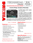
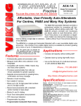
TECHNICAL
Practice
Practice
TELECOM SOLUTIONS
FOR THE
VC-1000
CCTV Camera
Controller
2 1 S T C E N T U RY
February 28, 2006
Provide Event-Triggered CCTV Camera
Switching for Two Zones - Expandable to Four
The VC-1000 Programmable CCTV Camera
Controller consists of two telco interface modules
each linked to a CCTV camera input and a combiner for output to a video monitor, television or
VCR.
Unlike passive or manual CCTV camera switchers, the VC-1000 continuously monitors for activity on its telco line circuits and instantly switches to
the appropriate camera when activity is detected.
During periods of inactivity, the VC-1000 can be programmed to provide no video output, output camera 1, output the last camera activated, or output the cameras sequentially. Two VC-1000’s can be stacked to cover four zones. Programming is done easily using dip switches.
Phone...715.386.8861
Features
• Automatic, instant switching to activated camera
• Supports 2 zones/entry points, expandable to 4
entry points (requires 2 units)
Applications
• Adds video switching capability to the following
Viking products:
-
1600A Series Emergency Phones
K-1900 Series Phones
K-1500 Series Phones
E-10, E-20A and E-30 Speaker Phones
W-1000, W-2000A and W-3000 Doorboxes
• Compatible with analog PABX/KSU extensions,
Viking doorboxes, entry phones, and emergency
phones
• Apartment entry
• Screw terminals for easy connection
• Security checkpoints
• Separate screw-terminal connections for camera
power and ground
• Multi-zone surveillance
• Rugged, durable relay switching for video control
• Dip switch programming for modes and camera
assignment
• Four inactive modes
• Activated by ringing or off-hook
• 12V 400mA DC output provided to operate two
CCTV cameras
• Can be configured to activate from a doorbell
[email protected]
h t t p : / / w w w. v i k i n g e l e c t r o n i c s . c o m
Specifications
Power: 120V AC/13.8V AC, 1.25A UL listed adapter provided
Power Output: 12V 400mA DC (total, for both cameras)
Dimensions: 133mm x 89mm x 44mm (5.25” x 3.5” x 1.75”)
Shipping Weight: .80 kg (1.7 lbs)
Environmental: 0° C to 32° C (32° F to 90° F) with 5% to 95%
non-condensing humidity
Relay Contact Rating: 1A 30VDC, 0.3A 110 VDC, 0.5A 125VAC
Connections: (20) cage clamp screw terminals
IF YOU HAVE A PROBLEM WITH A VIKING PRODUCT, PLEASE CONTACT: VIKING TECHNICAL SUPPORT AT (715) 386-8666
Our Technical Support Department is available for assistance Monday 8am - 4pm and Tuesday through Friday 8am - 5pm central time. So that we can give you better service, before you call please:
1. Know the model number, the serial number and what software version you have (see serial label).
2. Have your Technical Practice in front of you.
3. It is best if you are on site.
RETURNING PRODUCT FOR REPAIR
RETURNING PRODUCT FOR EXCHANGE
The following procedure is for equipment that needs repair:
1. Customer must contact Viking's Technical Support Department at 715-386-8666 to obtain a Return Authorization (RA)
number. The customer MUST have a complete description of the problem, with all pertinent information regarding the
defect, such as options set, conditions, symptoms, methods to duplicate problem, frequency of failure, etc.
2. Packing: Return equipment in original box or in proper packing so that damage will not occur while in transit. Static
sensitive equipment such as a circuit board should be in an anti-static bag, sandwiched between foam and individually boxed. All equipment should be wrapped to avoid packing material lodging in or sticking to the equipment. Include
ALL parts of the equipment. C.O.D. or freight collect shipments cannot be accepted. Ship cartons prepaid to:
Viking Electronics, 1531 Industrial Street, Hudson, WI 54016
3. Return shipping address: Be sure to include your return shipping address inside the box. We cannot ship to a PO Box.
4. RA number on carton: In large printing, write the R.A. number on the outside of each carton being returned.
The following procedure is for equipment that has failed out-of-box (within 10 days of purchase):
1. Customer must contact Viking’s Technical Support at 715-386-8666 to determine possible causes for the problem. The
customer MUST be able to step through recommended tests for diagnosis.
2. If the Technical Support Product Specialist determines that the equipment is defective based on the customer's input
and troubleshooting, a Return Authorization (R.A.) number will be issued. This number is valid for fourteen (14)
calendar days from the date of issue.
3. After obtaining the R.A. number, return the approved equipment to your distributor, referencing the R.A. number. Your
distributor will then replace the product over the counter at no charge. The distributor will then return the product to
Viking using the same R.A. number.
4. The distributor will NOT exchange this product without first obtaining the R.A. number from you. If you haven't
followed the steps listed in 1, 2 and 3, be aware that you will have to pay a restocking charge.
WARRANTY
Viking warrants its products to be free from defects in the workmanship or materials, under normal use and service, for a period of one year from the date of purchase from any authorized Viking distributor or 18 months from the date manufactured, which ever is greater. If at any time during the warranty period, the product is deemed defective or malfunctions, return the product to Viking Electronics, Inc., 1531 Industrial Street, Hudson, WI., 54016. Customer must contact Viking's
Technical Support Department at 715-386-8666 to obtain a Return Authorization (R.A.) number.
This warranty does not cover any damage to the product due to lightning, over voltage, under voltage, accident, misuse, abuse, negligence or any damage caused by use of the product by the purchaser or others.
Vikings sole responsibility shall be to repair or replace (at Viking's option) the material within the terms stated above. VIKING SHALL NOT BE LIABLE FOR ANY LOSS OR DAMAGE OF ANY KIND INCLUDING INCIDENTAL OR CONSEQUENTIAL DAMAGES RESULTING DIRECTLY OR INDIRECTLY FROM ANY BREACH OF ANY WARRANTY EXPRESSED OR IMPLIED, OR FOR ANY OTHER FAILURE OF THIS PRODUCT. Some states do not allow the exclusion or limitation of incidental or consequential damages, so this limitation may not apply to you.
THIS WARRANTY IS IN LIEU OF ALL OTHER WARRANTIES, EXPRESSED OR IMPLIED, INCLUDING THE WARRANTIES OF MERCHANTABILITY AND FITNESS FOR A PARTICULAR PURPOSE, WHICH ARE HEREBY EXCLUDED
BEYOND THE ONE YEAR DURATION OF THIS WARRANTY. Some states do not allow limitation on how long an implied warranty lasts, so the above limitation may not apply to you.
Installation
!
IMPORTANT: Electronic devices are susceptible to lightning and power station electrical surges from both the AC outlet and the telephone line.
It is recommended that a surge protector be installed to protect against such surges. Contact Panamax at (800) 472-5555 or Electronic Specialists
Inc. at (800) 225-4876.
A. Telco Wiring
The VC-1000 monitors for ringing and off-hook activity on two analog lines, doorboxes or entry phone circuits. Connect
as shown in the following diagrams.
1. Using with Viking Doorboxes
VIKING ©
120V AC
13.8V AC
Adapter
included
MODEL VC-1000
Compatible Viking Doorboxes:
W-1000, W-2000A and W-3000
(not included)
POWER 13.8 VAC
VIKING
ELECTRONICS
HUDSON, WI 54016
2 PORT VIDEO
CONTROLLER
LINE
INPUTS
Doorbox 1
W-2000A shown
(not included)
CAMERAS
LED1
IN USE
Unused Trunk
Input of PABX/KSU
LINE
OUTPUTS
VIDEO
OUT
COM
PORT
DIP SWITCH
ON
From
Doorbox 1
LINE 1
INPUT
SIG GND
VIDEO 1
12V GND
POWER
LINE 2
INPUT
SIG GND
VIDEO 2
12V GND
POWER
?
LED2
IN USE
1
LINE 1
OUT
LINE 2
OUT
SIG GND
VIDEO OUT
2
3
4
1 2 3 4
SIG GND
COM
Need More Information on Doorboxes?
Call (715) 386-4345 and select 170.
Doorbox 2
W-1000 shown
(not included)
From
Doorbox 2
2. Using with Viking Entry Phones
VIKING ©
120V AC
13.8V AC
Adapter
included
?
MODEL VC-1000
1600A Series, K-1900 Series, K-1700-3,
K-1500 Series, E-10 and E-20A
POWER 13.8 VAC
VIKING
ELECTRONICS
HUDSON, WI 54016
2 PORT VIDEO
CONTROLLER
Doorbox 1, K-1500-7
shown (not included)
Need More Information on the C-2000A?
Call (715) 386-4345 and select 156.
LINE
INPUTS
CAMERAS
LED1
C-2000A Advanced
Door Entry Controller
(not included)
Unused Stations
of PABX/KSU
IN USE
LINE
OUTPUTS
VIDEO
OUT
COM
PORT
DIP SWITCH
ON
LINE 1
INPUT
SIG GND
VIDEO 1
12V GND
POWER
LINE 2
INPUT
SIG GND
VIDEO 2
12V GND
POWER
LED2
IN USE
From
Doorbox 1
1
LINE 1
OUT
LINE 2
OUT
SIG GND
VIDEO OUT
SIG GND
COM
2
3
4
1 2 3 4
or
From
Doorbox 2
Compatible Viking Entry and
Emergency Phones (not included):
Doorbox 2, K-1700-3
shown (not included)
B. Video Wiring
Two video cameras can be wired to, and powered from, the VC-1000 as shown below. A single video output can be
wired directly to a video monitor/VCR, to the video input of a home television set, or to an RF modulator.
1. Industrial Application
Wire video signal directly to a TV / video monitor or video recorder as shown below.
VIKING ©
120V AC
13.8V AC
Adapter
included
MODEL VC-1000
POWER 13.8 VAC
VIKING
ELECTRONICS
HUDSON, WI 54016
Video
Signal
2 PORT VIDEO
CONTROLLER
Ground
CCTV Camera 1
(not included)
+12V
LINE
INPUTS
CAMERAS
Ground
LED1
Power
IN USE
LINE
OUTPUTS
VIDEO
OUT
COM
PORT
DIP SWITCH
LINE 1
INPUT
SIG GND
VIDEO 1
12V GND
POWER
LINE 2
INPUT
SIG GND
VIDEO 2
12V GND
POWER
LED2
ON
IN USE
1
TV / Video Monitor / VCR Recorder
(not included)
LINE 1
OUT
LINE 2
OUT
SIG GND
VIDEO OUT
SIG GND
COM
2
3
4
1 2 3 4
Power
Ground
TV's Video
Input
+12V
Video Signal
CCTV Camera 2
(not included)
Ground
Video Ground
Signal
Video
2. Home Application - Manual Switched Input
Wire video signal to home
TV’s video input. Manually
switch to that input to see
camera video.
VIKING ©
120V AC
13.8V AC
Adapter
included
MODEL VC-1000
POWER 13.8 VAC
VIKING
ELECTRONICS
HUDSON, WI 54016
Video
Signal
2 PORT VIDEO
CONTROLLER
Ground
+12V
LINE
INPUTS
Home TV / VCR Recorder
(not included)
CAMERAS
CCTV Camera 1
(not included)
Ground
LED1
Power
IN USE
LINE
OUTPUTS
VIDEO
OUT
COM
PORT
DIP SWITCH
ON
LINE 1
INPUT
SIG GND
VIDEO 1
12V GND
POWER
LINE 2
INPUT
SIG GND
VIDEO 2
12V GND
POWER
LED2
IN USE
1
LINE 1
OUT
TV's Video
Input
Ant In
LINE 2
OUT
SIG GND
VIDEO OUT
SIG GND
COM
2
3
4
1 2 3 4
Power
Ground
Video Signal
+12V
Video Ground
Coax RF
Ground
VCR
CCTV Camera 2
(not included)
Signal
Satellite Receiver
Video
3. Home Application - Automatic Switched Input
Wire video signal to an inexpensive RF modulator (Radio Shack # 15-1214 or equivalent) that automatically switches from
VCR/satellite to CCTV video when a signal is present. Note: For this application the TV must remain on channel 3 or 4. Set up
the VCR and satellite receiver to send the signal out on channel 3 or 4 and use the VCR’s tuner to select local broadcast stations.
VIKING ©
120V AC
13.8V AC
Adapter
included
MODEL VC-1000
POWER 13.8 VAC
VIKING
ELECTRONICS
HUDSON, WI 54016
Video
Signal
2 PORT VIDEO
CONTROLLER
Ground
Home TV / VCR Recorder
(not included)
+12V
LINE
INPUTS
CAMERAS
CCTV Camera 1
(not included)
Ground
LED1
Power
IN USE
LINE
OUTPUTS
VIDEO
OUT
COM
PORT
DIP SWITCH
ON
LINE 1
INPUT
SIG GND
VIDEO 1
12V GND
POWER
LINE 2
INPUT
SIG GND
VIDEO 2
12V GND
POWER
LED2
IN USE
1
Ant In
LINE 1
OUT
Video
Input
Coax RF
LINE 2
OUT
SIG GND
VIDEO OUT
SIG GND
COM
Video Signal
RF Modulator
Video Ground
VCR
Satellite Receiver
2
3
4
1 2 3 4
Power
Ground
+12V
Ground
?
Recommended RF Modulator:
Radio Shack #15-1214
Signal
Video
CCTV Camera 2
(not included)
C. Gang Wiring
VIKING ©
VIKING ©
MODEL VC-1000
MODEL VC-1000
VIKING
ELECTRONICS
HUDSON, WI 54016
POWER 13.8 VAC
VIKING
ELECTRONICS
HUDSON, WI 54016
POWER 13.8 VAC
Two VC-1000’s can be wired together to
support up to 4 zones/entry points. Do this
by wiring the COM PORT SIG screw terminals together and wiring the COM PORT
GND screw terminals together. The VIDEO
OUT screw terminals of both VC-1000’s can
be wired together in parallel to send video
signal to a monitor TV or video recorder.
2 PORT VIDEO
CONTROLLER
LINE
INPUTS
2 PORT VIDEO
CONTROLLER
LINE
INPUTS
CAMERAS
IN USE
TV / Video Monitor / VCR Recorder
(not included)
LINE
OUTPUTS
VIDEO
OUT
COM
PORT
DIP SWITCH
ON
IN USE
LINE 1
INPUT
SIG GND
VIDEO 1
12V GND
POWER
LINE
OUTPUTS
LED2
VIDEO
OUT
COM
PORT
DIP SWITCH
1
LINE 2
OUT
SIG GND
VIDEO OUT
SIG GND
COM
2
3
SIG GND
VIDEO 1
12V GND
POWER
LINE 2
INPUT
SIG GND
VIDEO 2
12V GND
POWER
IN USE
4
1 2 3 4
LINE 1
INPUT
LED2
ON
IN USE
LINE 1
OUT
CAMERAS
LED1
LED1
1
LINE 2
INPUT
SIG GND
VIDEO 2
12V GND
POWER
LINE 1
OUT
LINE 2
OUT
SIG GND
VIDEO OUT
SIG GND
COM
2
3
4
1 2 3 4
COM Port Signal
TV's Video
Input
COM Port Ground
Video Signal
Video Out Signal
Video Ground
Video Out Ground
Programming
A. Camera Assignment for Sequenced Video Feature
Use DIP switches 1 and 2 to assign video camera 1 and video camera 2 in use, and off if not installed. The ability to turn off a camera
position not being used will prevent the controller from sequencing
in an unused camera position (see Programming section B).
ON/OFF
ON
Camera 1 enabled
1
OFF
Camera 1 disabled
2
ON
Camera 2 enabled
DIP SWITCH
ON
Description
1
MODEL VC-1000
VIKING
ELECTRONICS
HUDSON, WI 54016
ON
POWER 13.8 VAC
Switch
VIKING ©
2 PORT VIDEO
CONTROLLER
LINE
INPUTS
OFF
1
2
3
4
CAMERAS
LED1
IN USE
1 2 3 4
LINE
OUTPUTS
VIDEO
OUT
COM
PORT
DIP SWITCH
ON
LINE 1
INPUT
SIG GND
VIDEO 1
12V GND
POWER
LINE 2
INPUT
SIG GND
VIDEO 2
12V GND
POWER
LED2
IN USE
2
OFF
Camera 2 disabled
1
LINE 1
OUT
LINE 2
OUT
SIG GND
VIDEO OUT
SIG GND
COM
2
3
4
1 2 3 4
B. Inactive Modes
DIP switches 3 and 4 are used to program what the VC-1000 does when all telco lines are inactive (not ringing or in-use). If “output
camera 1” mode is used, an additional VC-1000 ganged together must be set to “cameras disconnected” mode to prevent contentions. Otherwise, if two VC-1000’s are ganged together, both units must be programmed to the same inactive mode.
Switch 3
Switch 4 Description
OFF
OFF
All cameras are disconnected
OFF
ON
Output Camera 1 Note: An additional VC-1000 ganged together must be set to “cameras disconnected”.
ON
OFF
Remain connected to the last camera activated, until another camera is called into action
ON
ON
Sequenced Video (rotate every 4 seconds)
Operation
The VC-1000 allows multiple cameras to be concentrated down to one video signal, by switching to the camera at the zone/entry point
being used. When the VC-1000 detects ringing (voltage), off hook (loop current) of the entry phone or doorbox, or a doorbell button
pressed, it will connect that camera's video feed to the video output. This happens in a first come, first serve manner. When all telco lines
are idle (entry phones or doorboxes not in use), the VC-1000 can be programmed to do one of four operations:
1. Disconnect all cameras so there is no video output. This mode is very convenient when used in combination with a video RF
modulator, which automatically switches the video source in when a video signal is present. A home TV’s broadcast/satellite program
will be automatically interrupted to show video feed of the arriving guest (see Installation section C).
2. Connect video feed from camera 1.
3. Remain connected to the last camera active and continue feeding video from it until another camera is called into action.
4. Sequence video from all cameras connected, rotating every 4 seconds.
Product Support Line...715.386.8666
Fax Back Line...715.386.4345
Due to the dynamic nature of the product design, the information contained in this document is subject to change without notice. Viking Electronics, and its affiliates and/or
subsidiaries assume no responsibility for errors and omissions contained in this information. Revisions of this document or new editions of it may be issued to incorporate
such changes.
Fax Back Doc 185
Printed in the U.S.A.
ZF301950 Rev A