1
Model MTT1DSU
User Guide
Class A
Manual Declaration
NOTE: This equipment has been tested and found to comply with the
limits for a Class A digital , pursuant to Part 15 of the FCC Rules. These
limits are designed to provide reasonable protection against harmful
interference when the equipment is operated in a commercial environment. This equipment generates, uses, and can radiate radio frequency
energy, and if not installed and used in accordance with the User
Guide, may cause harmful interference to radio communications.
Operation of this equipment in a residential area is likely to cause
harmful interference, in which case the user will be required to correct
the interference at his own expense.
WARNING: Changes or modifications to this unit not expressly approved
by the party responsible for compliance could void the user's authority
to operate this equipment.
MultiDSU User Guide
82083200 Revision A
Model MTT1DSU
This publication may not be reproduced, in whole or in part, without prior
expressed written permission from Multi-Tech Systems, Inc. All rights
reserved.
Copyright © 1998, by Multi-Tech Systems, Inc.
Multi-Tech Systems, Inc. makes no representations or warranties with
respect to the contents hereof and specifically disclaims any implied
warranties of merchantability or fitness for any particular purpose.
Furthermore, Multi-Tech Systems, Inc. reserves the right to revise this
publication and to make changes from time to time in the content hereof
without obligation of Multi-Tech Systems, Inc. to notify any person or
organization of such revisions or changes.
Record of Revisions
Revision
Description
A
Manual released. All pages at rev A.
(8/14/98)
Patents
This Product is covered by one or more of the following U.S. Patent
Numbers: 5.301.274; 5.309.562; 5.355.365; 5.355.653; 5.452.289;
5.453.986. Other Patents Pending.
TRADEMARK
Trademark of Multi-Tech Systems, Inc. is the Multi-Tech logo.
Windows is a registered trademark of Microsoft.
Multi-Tech Systems, Inc.
2205 Woodale Drive
Mounds View, Minnesota 55112
(612) 785-3500 or (800) 328-9717
Fax 612-785-9874
Tech Support (800) 972-2439
BBS (612) 785-3702 or (800) 392-2432
Internet Address: http://www.multitech.com
Fax-Back (612) 717-5888
Contents
Chapter 1 - Introduction and Description
Introduction ................................................................................. 8
About This User Guide ................................................................ 9
Front Panel ................................................................................ 10
Back Panel ............................................................................... 11
LINE Connector .................................................................. 11
COMMAND Connector ........................................................ 11
Data Connector ................................................................... 11
POWER Connector ............................................................. 11
FCC Regulations for Telephone Line Interconnection ................. 12
Specifications ........................................................................... 14
T1 Line ............................................................................... 14
Data Port ............................................................................ 14
Electrical/Physical/Environmental ...................................... 14
Chapter 2 - Installation
Introduction ...............................................................................
Safety Warnings ........................................................................
Unpacking .................................................................................
MultiDSU Configuration .............................................................
Cabling Your MultiDSU ..............................................................
Configuration .............................................................................
16
16
16
17
19
21
Chapter 3 - Menu System
Introduction ............................................................................... 30
Configurations Menu ........................................................... 30
T1 Line Configuration Menu ....................................................... 30
Framing Format .................................................................. 31
Line Coding ........................................................................ 31
Line Type and Length .......................................................... 32
DS0 Speed/DS0 Allocation Menu .............................................. 32
DS0 Speed ......................................................................... 32
DS0 Allocation .................................................................... 32
Clocking Menu .......................................................................... 33
V.35 Port Menu ......................................................................... 33
Set Configurations .............................................................. 33
iv
Set and Save Configurations .............................................. 33
Reset to Factory Defaults ................................................... 34
Current Status Screen ........................................................ 34
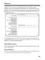
Statistics .................................................................................. 35
Out Of Sync Secs .............................................................. 35
Errored Secs ...................................................................... 35
Bursty Errored Secs ........................................................... 36
Severely Errored Secs ........................................................ 36
Failed Secs ........................................................................ 36
Controlled Slips .................................................................. 36
Framing Bit Errors ............................................................... 36
Bipolar Violations ................................................................ 36
Diagnostics ............................................................................... 37
System Information ................................................................... 38
Chapter 4 - Remote Configuration
Introduction ............................................................................... 40
Modem-Based Remote Configuration Procedure ................. 40
Chapter 5 - Diagnostics
Introduction ............................................................................... 42
Setup for Diagnostic Loopback Tests ........................................ 42
Diagnostics Methodology .......................................................... 42
Diagnostics Menu ..................................................................... 43
Local Loop Back ................................................................. 43
Remote Loop Back ............................................................. 43
Put Remote Into Loop Back ................................................ 44
Processor Loopback .......................................................... 44
Chapter 6 - Warranty, Service and Technical Support
Introduction ............................................................................... 46
Limited Warranty ................................................................. 46
On-line Warranty Registration .............................................. 47
Service ............................................................................... 47
About the Internet ............................................................... 48
About the Multi-Tech Fax-Back Service .............................. 48
v
Chapter 1 - Introduction
and Description
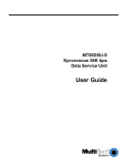
Introduction
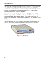
The Multi-Tech Systems MultiDSU (Model number MTT1DSU) is a low
cost, full-featured T1-FT1 Data Service Unit (DSU). The MultiDSU
provides an interface between point-to-point T1 or Fractional T1 service
and the end user's Data Terminal Equipment (DTE). This unit also
provides Facility Data Link (FDL) support.
Housed in a compact, durable housing, the MultiDSU supports D4 or
ESF framing and AMI or B8ZS line coding on the T1 Line and supports
synchronous data rates from 56 kbps to 1.536 Mbps to the DTE. A
single V.35 (Winchester 34-pin) physical interface is the Data port to the
DTE device.
This unit enables you to run complete diagnostics (loopback tests on
your T1 line or your local or remote DSU) from your PC or terminal.
Figure 1-1. MultiDSU
8
About This User Guide
This user guide describes the MultiDSU and explains how to install and
configure the unit. The information contained in each chapter is as
follows:
Chapter 1 - Introduction and Description
Chapter 1 describes the MultiDSU and provides a review of this user
guide. This chapter describes the front panel indicators and back panel
connectors and switch. Applicable FCC regulations and a list of relevant
specifications are provided at the end of the chapter.
Chapter 2 - Installation
Chapter 2 lists the safety warnings that are applicable to the MultiDSU
then steps you through the process of unpacking your MultiDSU,
connecting signal cables and power, and configuring your MultiDSU for
operation.
Chapter 3 - Menu System
Chapter 3 describes the various options available on all the menus and
submenus used to configure and operate the MultiDSU.
Chapter 4 - Remote configuration
This chapter provides instructions for modem-based remote configuration of the MultiDSU.
Chapter 5 - Diagnostics
Chapter 5 describes how to set up for, and perform, several types of
diagnostic loopback tests for the MultiDSU.
Chapter 6 - Warranty, Service and Technical Support
Chapter 6 provides instructions on getting service for your MultiDSU at
the factory, and includes a statement of the limited warranty and space
for recording information about your MultiDSU prior to calling MultiTech's Technical Support. The final sections explain how to obtain
technical support through our Web site and ftp site on the Internet or our
fax-back system.
9
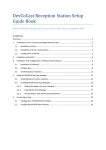
Front Panel
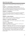
The front panel contains three sets of LEDs that provide the status of
the MultiDSU and its data and T1 connections. The Data LEDs display
the status and activity of the V.35 Data port. The T1 Line LEDs show
whether the T1 Line is online or in a failure mode. Two monitor jacks
enable you to monitor the T1 line with external test equipment.
Figure 1-1. Front Panel
PWR
BTG
TST
(Power) Lights when the power switch is in the "1"
(On) position and the MultiDSU is powered by the
external power supply.
(Booting) Lights while the MultiDSU is booting.
(Test) Lights during diagnostic tests and during any
loopback tests.
Data
XMT
RCV
RTS
(Transmit) Lights when packets are being transmitted
to the T1 line from the DTE device.
(Receive) Lights when packets are being received
from the T1 line by the DTE device.
(Ready to Send) Lights whenever the DTE device is
receiving RTS.
T1 Line
ONL
SLS
RED
YEL
(Online) Lights whenever a carrier signal is detected
and no error conditions are present.
(Sync Loss) Lights when there is a Loss of Sync in the
input signal .
(Warning) Lights when there is a red alarm on the T1
line.
(Warning) Lights when there is a yellow alarm on the
T1 line.
Monitor jacks
XMT
RCV
10
(Transmit) monitors transmit data on the T1 line.
(Receive) monitors receive data on the T1 line.
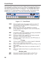
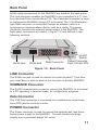
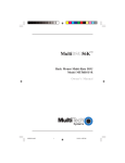
Back Panel
All the cable connections for the MultiDSU are made at the back panel.
The Line connector enables the MultiDSU to be connected to a T1 line
from the local Telco central office (CO). The Command connector is used
to configure the MultiDSU using a PC or terminal. The V.35 Winchestertype Data connector is connected through an adapter cable to a
synchronous communications device such as a router. The power
connector connects the external power supply to the MultiDSU. The
back panel connectors are shown in Figure 1-2 and defined in the
following sections.
LINE
COMMAND
POWER
1
0
RJ48 Jack
RJ45 Jack
Data Connector
On/Off
Switch
Power Connector:
6-pin Circular DIN
Figure 1-2. Back Panel
LINE Connector
The RJ48 Line jack is used to connect to a point-to-point T1 line from
your local Telco or back to back to the Line jack of another MultiDSU.
COMMAND Connector
The RJ45 Command jack is used to connect the MultiDSU to a terminal
or a PC operating in terminal mode, for configuration purposes.
Data Connector
The V.35 Data connector is connected to a synchronous communications (DTE) device such as a router.
POWER Connector
The Power connector is used to connect the external wall type transformer power supply to the MultiDSU. The wall transformer plugs
directly into a grounded duplex AC outlet.
11
FCC Regulations for Telephone Line Interconnection
1.This equipment complies with Part 68 of the Federal
Communications Commission (FCC) rules. On the outside
surface of this equipment is a label that contains, among other
information, the FCC registration number and ringer equivalence
number (REN). If requested, this information must be provided to
the telephone company.
2. As indicated below, the suitable jack (Universal Service Order
Code connecting arrangement) for this equipment is shown. If
applicable, the facility interface codes (FIC) and service order
codes (SOC) are shown. An FCC-compliant telephone cord and
modular plug is provided with this equipment. This equipment is
designed to be connected to the telephone network or premises
wiring using a compatible modular jack which is Part 68
compliant. See installation instructions for details.
3. The ringer equivalence number (REN) is used to determine the
number of devices which may be connected to the telephone
line. Excessive REN’s on the telephone line may result in the
devices not ringing in response to an incoming call. In most, but
not all areas, the sum of the REN’s should not exceed five (5.0).
To be certain of the number of devices that may be connected
to the line, as determined by the total REN’s, contact the
telephone company to determine the maximum REN for the
calling area.
4. If this equipment causes harm to the telephone network, the
telephone company will notify you in advance. But if advance
notice isn’t practical, the telephone company will notify the
customer as soon as possible. Also, you will be advised of your
right to file a complaint with the FCC if you believe it is
necessary.
5. The telephone company may make changes in its facilities,
equipment, operations, or procedures that could affect the
operation of the equipment. If this happens, the telephone
company will provide advance notice in order for you to make
12
necessary modifications in order to maintain uninterrupted
service.
6. If trouble is experienced with this equipment (the model of which
is indicated below) please contact Multi-Tech Systems, Inc. at
the address shown below for details of how to have repairs
made. If the trouble is causing harm to the telephone network,
the telephone company may request you remove the equipment
from the network until the problem is resolved.
7. No repairs are to be made by you. Repairs are to be made only
by Multi-Tech Systems or its licensees. Unauthorized repairs
void registration and warranty.
8. This equipment cannot be used on public coin service provided
by the telephone company. Connection to Party Line Service is
subject to state tariffs. (Contact the state public utility
commission, public service commission or corporation
commission for information.
9. If so required, this equipment is hearing-aid compatible.
Manufacturer:
Trade Name:
Model Number:
FCC Registration #:
Ringer Equivalence:
SOC Codes:
Modular Jack
Service Center in USA:
Multi-Tech Systems, Inc.
MultiDSU
MTT1DSU
AU7USA-25529-DE-E
N/A
6.0N
RJ48 for T1 connection
Multi-Tech Systems Inc.
2205 Woodale Drive
Mounds View, MN 55112
Voice (612) 785-3500 or
(800) 328-97174
FAX (612) 785-9874
13
Specifications
T1 Line
•
•
•
•
•
Single T1 Line port with synchronous data format
AMI or B8ZS line coding
D4 Superframe or Extended Superframe framing support
1 to 24 channels at 56 kbps or 64 kbps each
T1 line connector is an RJ48 jack
Data Port
•
•
•
•
Single (V.35 DCE) port for synchronous data
Operation at data rates from 56 kbps to 1.536 Mbps
Local and remote loopback capability
Extensive built-in test capabilities
Electrical/Physical/Environmental
• Voltage - 115v AC, 50/60 Hz (for power adapter)
• Power - 10 watts (est.)
• Dimensions - 6" W x 1.625" H x 9.00" L
- 15.24 cm x 4.13 cm x 22.86 cm
• Weight - 2.0 pounds
• Temperature
Operating: - 32° to 122° F (0° to 50° )
Storage: - 4° to 158° F (-20° to 70° )
• Relative Humidity - Up to 95%, non-condensing
14
Chapter 2 - Installation
Introduction
This chapter provides the safety warnings applicable to the MultiDSU
and describes the unpacking of the MultiDSU, cable connections, and
how to configure the unit dependent on your site situation. Once the
MultiDSU is configured, then the Data port can be connected to your
DTE device.
Safety Warnings
1. Never install telephone wiring during a lightning storm.
2. Never install telephone jacks in wet locations unless
the jack is specifically designed for wet locations.
3. Never touch uninsulated telephone wires or terminals unless the
telephone line has been disconnected at the network interface.
4.
Use caution when installing or modifying telephone lines.
5. Avoid using a telephone (other than a cordless type) during an
electrical storm. There may be a remote risk of electrical shock
from lightning.
6. Do not use the telephone to report a gas leak in the vicinity of the
leak.
Unpacking
The shipping box contains the MultiDSU, power adapter, Command
port cable, and your user's manual. Inspect the contents for signs of
any shipping damage. If damage is observed, do not power up the unit,
contact Multi-Tech's Technical Support for advice (refer to Chapter 6 Warranty, Service and Technical Support). If no damage is observed,
remove all items from the box, place the MultiDSU in its final location,
and connect your cables and power supply.
16
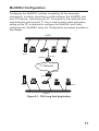
MultiDSU Configuration
Configuring the MultiDSU involves completing all the necessary
connections, including connecting a cable between the MultiDSU and
your DTE device, connecting your PC or terminal to the command port,
connecting the point-to-point T1 line or back-to-back cable and power,
setting up the PC or terminal to configure the MultiDSU, and finally
configuring the MultiDSU using the Configuration procedure provided in
this chapter.
LAN 1
®
ech
TSystems
PC
Router
PC
Workstation
Server
Data Port
MultiDSU
T1 Network
Data Port
MultiDSU
®
ech
TSystems
Server
PC
Router
PC
Workstation
LAN 2
Figure 2-1. CSU Long Haul Application
17
LAN 1
®
ech
TSystems
PC
Router
PC
Workstation
Server
Data Port
MultiDSU
(Master)
RJ48
back-to-back
connection
(with T1
crossover
cable)
Data Port
MultiDSU
(Slave)
®
ech
TSystems
Server
PC
Router
PC
Workstation
LAN 2
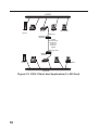
Figure 2-2. DSX-1 Short Haul Application (0 < 655 Feet)
18
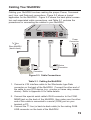
Cabling Your MultiDSU
Cabling your MultiDSU involves making the proper Power, Command
port, Line, and Data port connections. Figure 2-2 shows a typical
application for the MultiDSU. Figure 2-3 shows the back panel connectors and associated cable connections, and Table 2-1 contains the
procedures for connecting the cables to your MultiDSU.
LINE
COMMAND
POWER
1
0
Power
Connection
To Telco
or
Slave MultiDSU
(back to back)
Device
Connection
PC
Connection
Figure 2-3. Cable Connections
Table 2-1. Cabling the MultiDSU
1. Connect a V.35 interface cable to the Winchester type Data
connector on the back of the MultiDSU. Connect the other end of
the cable to your DTE device (e.g., a router or frame relay access
device). Refer to Appendix A for cable details.
2. Connect the special serial cable's RJ45 connector to the COMMAND jack on the back of the MultiDSU, then make sure the other
end of this cable is connected to a serial (COM) port on your
terminal or PC.
3. Connect the T1 line (or back-to-back cable) to the mating RJ48
LINE connector on the back of the MultiDSU.
19
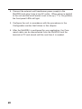
4. Connect the external wall transformer power supply to the
MultiDSU and plug it into a live AC outlet. When power is applied
to the unit and the on/off switch is set to the up ("1" or On) position,
the front panel LEDs will light.
5. Configure the unit in accordance with the procedures in the
Configuration section that follows in this chapter.
6. After the MultiDSU is configured for your application, the Command cable can be disconnected from the MultiDSU and the
terminal or PC and stored until the next time it is needed.
20
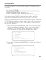
Configuration
If you are connecting to a Telco, get the following T1 information from
your Telco :
Line Code: AMI/B8ZS__________________________________
Framing Format: D4/ESF________________________________
Available bandwidth: Full T1 (24 DS0s), or
Number of DS0s and which DS0 assignments, if FT1. _________
If you are using your MultiDSU as a short-haul modem, select the
identical line coding and framing format to be used in both units.
Power up a terminal or PC running communications software. When the
T1 DSU Main Menu appears on your screen, perform the procedures in
the rest of this section, then run each of the loopback tests to check all
the lines and interfaces.
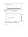
1. Apply power to your terminal or PC. After the terminal or pc boots
up, run communications software. Set up your communications
software for 19.2K bps, 8N1 (8-bits, no parity, and 1-stop bit).
Press the ENTER key to display the MultiDSU Main Menu.
T1 DSU Main Menu
1.
2.
3.
4.
5.
Configurations
Current Status
Statistics
Diagnostics
System Information
Enter Selection (-(previous), q(uit), <1>): _
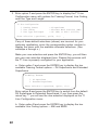
2. Enter option 1 and press the ENTER key to display the Configurations menu.
Configurations
1.
2.
3.
4.
5.
6.
7.
T1 Line Configuration
DS0 Speed/DS0 Allocation
Clocking
V.35 Port
Set configurations
Set and Save configurations
Reset to Factory Defaults
Enter Selection (-(previous), q(uit), <1>): _
21
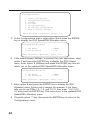
3. Enter option 1 and press the ENTER key to display the T1 Line
Configuration menu with options for Framing Format, Line Coding,
and Line Type and Length.
T1 Line Configuration
1. Framing Format
2. Line Coding
3. Line Type and Length
: D4 Superframe
: Alternate Mark Inversion (AMI)
: CSU (0db) or DSX-1 (0-133ft)
Enter Selection (-(previous), q(uit), <1>): _
If any of these default selections (shown) are incorrect for your
particular application, enter the corresponding option number to
display the menu with the available alternate selections. (See
substeps a through c.)
Make your new selection and press the ENTER key; you will then
see your new selection displayed here. Repeat this process until
the T1 Line is properly configured for your application.
a. Enter option 1 and press the ENTER key to display the two
available Framing Format options -- D4 Superframe and Extended
Superframe.
Framing Format
1. D4 Superframe
2. Extended Superframe
Enter Selection (-(previous), q(uit), <1>): _
Enter option 2 and press the ENTER key to switch from the default
D4 Superframe to Extended Superframe. If you then press the
minus key "-" you will see the new selection displayed on the T1
Line Configuration menu.
b. Enter option 2 and press the ENTER key to display the two
available Line Coding options -- AMI and B8ZS.
22
Line Coding
1. Alternate Mark Inversion (AMI)
2. Binary 8 Zero Substitution (B8ZS)
Enter Selection (-(previous), q(uit), <1>): _
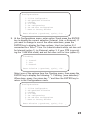
Enter option 2 and press the ENTER key if you need to switch from
the default AMI to B8ZS. You will then see the new selection
displayed on the T1 Line Configuration menu.
c. Enter option 3 and press the ENTER key to display the eight
available selections for Line Type and Length.
Line Type and Length
1.
2.
3.
4.
5.
6.
7.
8.
CSU (0db) or DSX-1 (0-133ft)
DSX-1 (133-266ft)
DSX-1 (266-399ft)
DSX-1 (399-533ft)
DSX-1 (533-655ft)
CSU (7.5db)
CSU (15db)
CSU (22db)
Enter Selection (-(previous), q(uit), <1>): _
Select an option and press the ENTER key; you will then see the
new selection displayed on the previous menu.
4. Press the minus key "-" and the ENTER key again to return to the
Configurations menu.
23
Configurations
1.
2.
3.
4.
5.
6.
7.
T1 Line Configuration
DS0 Speed/DS0 Allocation
Clocking
V.35 Port
Set configurations
Set and Save configurations
Reset to Factory Defaults
Enter Selection (-(previous), q(uit), <1>): _
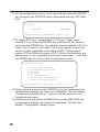
5. At the Configurations menu, enter option 2 and press the ENTER
key to display the DS0 Speed/DS0 Allocation menu.
DS0 Speed/DS0 Allocation
1. DS0 Speed
2. DS0 Allocation
: 64Kbps
: 1-24
Enter Selection (-(previous), q(uit), <1>): _
6. If the default speed, 64Kbps, is incorrect for your application, enter
option 1 and press the ENTER key to display the DSO Speed
menu. Enter option 2 (56Kbps) and press the ENTER key. this will
return you to the updated DS0 Speed/DS0 Allocation menu.
DS0 Speed/DS0 Allocation
1. DS0 Speed
2. DS0 Allocation
: 56Kbps
: 1-24
Enter Selection (-(previous), q(uit), <1>): _
7. Enter option 2 and press the ENTER key to display the DS0
Allocation menu. Enter a list of ranges; for example, if the Telco
tells you to use DS0s 1-5, 7, 9 and 12-15, then enter "1-5,7,9,1215" and press the ENTER key. This returns you to the updated DS0
Speed/DS0 Allocation menu.
8. Press the minus "-" key, then press the ENTER key to return to the
Configurations menu.
24
Configurations
1.
2.
3.
4.
5.
6.
7.
T1 Line Configuration
DS0 Speed/DS0 Allocation
Clocking
V.35 Port
Set configurations
Set and Save configurations
Reset to Factory Defaults
Enter Selection (-(previous), q(uit), <1>): _
9. At the Configurations menu, enter option 3 and press the ENTER
key to display the current selection (Internal, Line, or External). If
you want to change to one of the other selections, press the
ENTER key to display the three options. Use Line (option 2) if
connected to a Telco T1 line. For a back-to-back setup, set one unit
for Internal (option 1) (or External, option 3, if your DTE is providing the 1.544 MHz clock) and set the other unit for Line (option 2).
Clocking
1. Internal
2. Line
3. External
Enter Selection (-(previous), q(uit), <1>): _
Select one of the options from the Clocking menu, then press the
ENTER key to display the following "1. Clocking: (new selection)."
When done, press the minus key "-" and then the ENTER key to
return to the Configurations menu.
Configurations
1.
2.
3.
4.
5.
6.
7.
T1 Line Configuration
DS0 Speed/DS0 Allocation
Clocking
V.35 Port
Set configurations
Set and Save configurations
Reset to Factory Defaults
Enter Selection (-(previous), q(uit), <1>): _
25
10. At the configurations menu, enter option 4 and press the ENTER
key to display the RTS/DTR menu associated with the V.35 Data
Port.
V.35 Port
1. Force RTS
: Independent
Enter Selection (-(previous), q(uit), <1>): _
11.To toggle RTS from "Independent" to "Forced," enter option
number 1, then press the ENTER key and select 2 (for Forced)
and press the ENTER key. You will then see the updated V.35 Port
menu. Use "Forced" if you want CTS to stay high as long as the
carrier is high, regardless of the state of RTS; "Independent"
means CTS will follow the state of RTS. When the selections are
appropriate for your application, press the minus key "-" and then
the ENTER key to return to the Configurations menu.
Configurations
1.
2.
3.
4.
5.
6.
7.
T1 Line Configuration
DS0 Speed/DS0 Allocation
Clocking
V.35 Port
Set configurations
Set and Save configurations
Reset to Factory Defaults
Enter Selection (-(previous), q(uit), <1>): _
12. Enter option 5 and press the ENTER key to set (implement) the
configuration settings you have just completed. This will display
"Configuration Setting Done" and you will be returned to the
Configurations menu.
13. Enter option 6 and press the ENTER key to set AND SAVE the
configuration settings you have just completed. This will also
display "Configuration Setting Done."
26
T1 DSU Main Menu
1.
2.
3.
4.
5.
Configurations
Current Status
Statistics
Diagnostics
System Information
Enter Selection (-(previous), q(uit), <1>): _
27
28
Chapter 3 - Menu System
Introduction
The menu system for the MultiDSU provides a set of user-friendly
configuration menus that are accessible from a main menu. The Main
Menu contains four options that enable you to configure your MultiDSU,
check the current operating status, display hourly and daily statistics, or
run diagnostic tests; you can also exit (quit) the command mode from
the Main Menu.
T1 DSU Main Menu
1.
2.
3.
4.
5.
Configurations
Current Status
Statistics
Diagnostics
System Information
Enter Selection (-(previous), q(uit), <1>):
_
To select one of the four main options from the Main Menu, enter the
number corresponding to the option and press the ENTER key to open
the associated submenu.
Configurations Menu
The Configurations menu provides various options for configuring the
T1 Line, including DS0 speed and allocation, selection of the source for
clocking. This menu also enables the usere to select "Forced" or
"Independent" RTS or DTR on the Data port. Other options enable the
user to set the configurations, set and save them, or reset the unit to its
factory defaults.
T1 Line Configuration Menu
This menu enables you to select the framing format, line coding, and
line type and length to match the characteristics of the T1 line provided
by your Telco or, for back-to-back connections to set the Master/Slave
units to identical settings.
30
T1 Line Configuration
1. Framing Format
2. Line Coding
3. Line Type and Length
: D4 Superframe
: Alternate Mark Inversion (AMI)
: CSU (0db) or DSX-1 (0-133ft)
Enter Selection (-(previous), q(uit), <1>): _
Framing Format
The MultiDSU supports two types of framing formats: D4 Superframe
(D4) and Extended Superframe (ESF).
The D4 Superframe option (option 1) is a 193-bit frame format in which
the 193rd bit has framing and signaling information. A D4 superframe
consists of 12 frames.
The Extended Superframe (ESF) option (option 2) is similar to D4
except that it consists of 24 frames instead of 12 frames and provides
CRC error detection and a 4 kHz Facility Data Link (FDL).
Line Coding
The MultiDSU supports two types of line coding: AMI and B8ZS.
The Alternate Mark Inversion (AMI) option (option 1) is a bipolar coding
scheme in which successive ones alternate in polarity to prevent a
Bipolar Violation (BPV). A BPV occurs when two consecutive ones are
the same polarity. When AMI is selected, the digital data stream from the
user equipment on the data port is converted into this bipolar format to
be transmitted over the T1 line.
The B8ZS option (option 2) is a coding technique used to satisfy the
ones density requirements of the T1 carrier facilities while also allowing
clear channel data. Since the system timing is recovered from the pulse
width of the ones, it is important to ensure that there is an adequate
proportion of ones in the data stream. If the data stream contains more
than 8 consecutive zeroes - a condition that could disrupt system timing
- B8ZS substitutes a predetermined pattern for the zeroes. This substitution intentionally causes a BPV to occur, alerting the unit on the receiving end that a substitution has taken place.
31
Line Type and Length
The line type and line length options enable the user to configure the
MultiDSU to match the characteristics of the T1 line.
The default selection is CSU (0db) or DSX-1 (0-133ft). CSU is a long
haul line type that allows the DSX-1 signal to be transmitted up to 6000
ft at Line Build Out (LBO) options of 0 dB, -7.5 dB, -15 dB, or -22.5 dB.
If the line type is DSX-1, you can select any of 5 available ranges of line
length up to 655 ft, maximum. DSX-1 is a short haul line type often
referred to as "cross-connect," especially within Telco central offices.
DS0 Speed/DS0 Allocation Menu
This menu enables you to configure the DS0 speed and (for Fractional
T1 only) the DS0 allocation.
DS0 Speed/DS0 Allocation
1. DS0 Speed
2. DS0 Allocation
: 64Kbps
: 1-24
Enter Selection (-(previous), q(uit), <1>): _
DS0 Speed
The default is 64Kbps clear channel communications; however, you can
also select 56Kbps.
Each of the 24 DS0 signals in a full T1 is 64 kbps for a total bandwidth of
1.536 Mbps. When 8 kbps is added to the 24 DS0 time slots, the
resulting data rate is 1.544 Mbps, which is referred to as the DS1 signal.
DS0 Allocation
This option enables you to configure the MultiDSU to match the bandwidth used. For full T1, use the default, "1-24." For Fractional T1 (FT1)
enter the range(s) of DS0s available on your T1 line; e.g., "1-10" or "110,20-24." All the DS0s are assigned to the Data port of the MultiDSU.
32
Clocking Menu
This menu enables you to select the clock timing (Internal, Line, or
External) for the MultiDSU. If you are connecting to a Telco, choose
option 2, "Line." For a back-to-back setup, set one unit for Internal
(option 1) (or External, option 3, if your DTE is providing the 1.544 MHz
clock) and set the other unit for Line (option 2).
Clocking
1. Internal
2. Line
3. External
Enter Selection (-(previous), q(uit), <1>): _
V.35 Port Menu
Selecting option 4 on the Configurations menu displays the V.35 Port
menu in which "Independent" is the default mode for RTS. "Independent" means CTS will follow the state of RTS. Toggle it to "Forced" if you
want CTS to stay high as long as the carrier is high, regardless of the
state of RTS.
V.35 Port
1. Force RTS
: Independent
Enter Selection (-(previous), q(uit), <1>): _
Set Configurations
The Configurations menu also enables you to "Set" any configuration
changes you have made since last using this command (or since the
unit was last powered On). Selecting option 5 and pressing the ENTER
key displays the line, "Configuration Setting Done" and returns you to
the Configurations menu. If the MultiDSU loses power, these settings
will be lost.
Set and Save Configurations
The Configurations menu also enables you to "Set and Save" Configurations. Selecting option 6 and pressing the ENTER key displays the
line, "Configuration Setting Done" and returns you to the Configurations
33
menu. Once they are saved, these settings will be retained if the
MultiDSU happens to lose power or is turned Off.
Reset to Factory Defaults
The Configurations menu also enables you to reset the MultiDSU to the
factory defaults by selecting option 7 and pressing the ENTER key.
Current Status Screen
Selecting option 2 on the Main Menu displays the Current Status
screen which displays the line status, receive level range, and the
number of bipolar violations, framing bit errors, and out-of-sync
multiframes. This screen enables you to see if any errors have occurred,
and provides details concerning any current error status.
Current Status
Line Status
:Red Alarm, Sync Loss
Receive Level
:-15db to -22db
Bipolar Violations
:150
Framing Bit Errors
:1000
Multiframes Out Of Sync
:10
Press <Return> to display again or M to return to menu (M, <Return>):
34
_
Statistics
Selecting option 3 on the Main Menu displays the Statistics. This screen
enables you to view any of eight different types of hourly or daily
statistics. The Hourly Statistics are displayed first, followed by the Daily
Statistics. From these performance data you can produce reports for the
previous 24 hours in 15-minute increments. Following is the format of
the Statistics screen:
------------------------------------Hourly Statistics ------------------------------------Error Name 0 1 2 3 4 5 6 7 8 9 10
-----------------------------------------------------------------------------------------------Out Of Sync Secs
Errored Secs
Bursty Secs
Severely Errored Secs
Failed Secs
Controlled Slips
Framing Bit Errors
Bipolar Violations
--------------------------------------Daily Statistics ------------------------------------Error Name
0
1
2
3
4
5
6
-----------------------------------------------------------------------------------------------Out Of Sync Secs
Errored Secs
Bursty Secs
Severely Errored Secs
Failed Secs
Controlled Slips
Framing Bit Errors
Bipolar Violationsps
The Statistics screen provides information concerning the operation of
the MultiDSU that can aid you in testing for problems. The T1 Errors are
defined in the following paragraphs:
Out Of Sync Secs
Out Of Sync Seconds (OOS) are seconds containing frames that could
not be transmitted.
Errored Secs
Errored Seconds (ES) are seconds containing one or more ESF errors
(i.e., one or more CRC6 errors or one or more OOFs).
35
Bursty Errored Secs
Bursty Errored Seconds (BES) are seconds containing 2 to 319 CRC6
errors.
Severely Errored Secs
Severely Errored Seconds (SES) are seconds with 320 or more CRC6
errors.
Failed Secs
Failed Seconds are seconds that failed due to one or more errors.
Controlled Slips
Controlled Slips (CS) occur when the receiving device either replicates
or deletes a DS1 frame.
Framing Bit Errors
Framing Bit Errors (FBE), also called Out Of Frame (OOF) errors, are
two frame bit errors in six consecutive frame bits.
Bipolar Violations
Bipolar Violations (BPV) occur when two adjacent bits are of same
polarity.
36
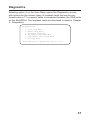
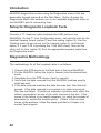
Diagnostics
Selecting option 4 on the Main Menu opens the Diagnostics screen,
with options for the various types of loopback tests that can be performed when a T1 crossover cable is connected between the LINE jacks
on two MultiDSUs. The loopback tests are discussed in detail in Chapter
5 - Diagnostics.
Diagnostics
1.
2.
3.
4.
5.
6.
Local Loop Back
Remote Loop Back
Processor Loop Back
Put Remote Into Loop Back
Take Remote Out of Loop Back
End Loop Back
Enter Selection (-(previous), q(uit), <1>):
_
37
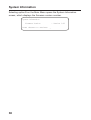
System Information
Selecting option 5 on the Main Menu opens the System Information
screen, which displays the firmware version number.
System Information
Firmware Version
Press <Return> to continue: _
38
: Version 1.00
Chapter 4 - Remote
Configuration
Introduction
Remote configuration of the MultiDSU involves using modems to
communicate from the local PC or terminal to the remote MultiDSU,
where a special Remote Configuration Cable is used to link the receiving modem to the Command port of the MultiDSU.
Modem-Based Remote Configuration Procedure
1. At the remote site, connect a special cable (Remote Configuration
Cable) to the Command port jack on the back panel of the MultiDSU and the RS232 connector on the modem. The special cable
is a serial cable with male connectors on both ends. Refer to
Appendix A for cable details.
2. Connect the modem to your local telephone line.
3. Provide your telephone number to the person verifying your
configuration.
4. At the main site, connect your local PC to a modem that is connected to a dial-up line.
5. Apply power to your terminal or PC. After the terminal or pc boots
up, run communications software. Set up your communications
software for 19.2K bps, 8N1 (8-bits, no parity, and 1-stop bit) and
call the remote modem.
6. Type "menu," then press the ENTER key to display the MultiDSU
Main Menu.
7. When done, disconnect the Remote Configuration Cable from the
modem and the MultiDSU at the remote location.
40
Chapter 5 - Diagnostics
Introduction
MultiDSU diagnostics involve using the Diagnostics menus that are
accessible through option 4 on the Main Menu. Option 4 opens the
Diagnostics Menu that enables you to run loopback diagnostic tests on
the MultiDSU and its connecting lines.
Setup for Diagnostic Loopback Tests
Connect a T1 crossover cable between the LINE jacks on two
MultiDSUs. On the T1 Line Configuration menu, set up both units for the
identical framing format (option 1) and line coding (option 2). Use the
Clocking menu to set up one unit for Internal (option 1) (or External,
option 3, if your DTE is providing the 1.544 MHz clock), then set the
other unit for Line (option 2). Run the appropriate loopback tests from
the Diagnostics menu.
Diagnostics Methodology
The methodology for all the loopback tests is as follows:
1 Connect the DTE device to the Data port of the local MultiDSU.
2 Put the MultiDSU (either the local or remote) into the desired test
mode.
3 Send data from the DTE device (local or remote).
4 Verify that the data received from the MultiDSU matches exactly
what was sent.
5 If the data received matches the data that was sent, then the test
passed. If the data received is corrupted or no data is received,
then the test failed. A failed test indicates a problem with either the
cables, connections, or one of the units involved in the test. If the
cause of the failure is not readily apparent, try using the process of
elimination to isolate the trouble spot(s). If there is still no clear
cause of the problem, follow the steps provided in Chapter 6 to
contact Tech support.
42
Diagnostics Menu
The Diagnostics menu enables you to run (and end) any of four different
loopback tests, return to the previous menu, or exit (quit) the command
mode.
Diagnostics
1.
2.
3.
4.
5.
6.
Local Loop Back
Remote Loop Back
Processor Loop Back
Put Remote Into Loop Back
Take Remote Out of Loop Back
End Loop Back
Enter Selection (-(previous), q(uit), <1>):
_
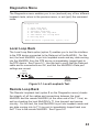
Local Loop Back
The Local Loop Back option (option 1) enables you to test the interface
to the DTE device connected to the Data port of the MultiDSU. For this
test, the local MultiDSU is put into loopback mode and any data coming
into the MultiDSU from the DTE device is immediately looped back to
the DTE device. See Figure 5-1. Use this test to verify that the Data port
cable and its connections are OK, and that the MultiDSU's Data port
settings are correct.
Local
Loopback
T1 Line
Mux
MultiDSU
Mux
Remote
MultiDSU
Figure 5-1. Local Loopback Test
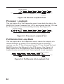
Remote Loop Back
The Remote Loopback test (option 2 on the Diagnostics menu) checks
the integrity of all the cables and connections between the local
MultiDSU and the remote MultiDSU (at the other end of the T1 line) as
well as checking the local MultiDSU's T1 Line transmit and receive
circuitry. For this test, the local MultiDSU is put into loopback mode and
any data coming into its T1 Line port is immediately looped back over
the T1 line to the remote MultiDSU. See Figure 5-2.
43
Remote Loopback
Mux
MultiDSU
T1 Line
Mux
Remote
MultiDSU
Figure 5-2. Remote Loopback Test
Processor Loopback
This test (option 3 on the Diagnostics menu) loops back the data in the
MultiDSU's Central Processor Unit (CPU) and assures that the CPU and
the T1 transceiver are communicating correctly. See Figure 5-3.
Processor Loopback
Mux
MultiDSU
T1 Line
Mux
Remote
MultiDSU
Figure 5-3. Processor Loopback Test
Put Remote Into Loop Back
This test (option 4 on the Diagnostics menu) checks the integrity of a
remote MultiDSU by putting it into loopback mode so anything it
receives over the T1 line is returned over the T1 line, through the local
MultiDSU and out the Data port to the DTE device. See Figure 5-4.
Select option 5 on the Diagnostics menu to take the remote out of
loopback mode and end the test. Select option 6 to end loop back.
Put Remote into Loopback
Mux
MultiDSU
T1 Line
Mux
Remote
MultiDSU
Figure 5-4. Put Remote Into Loopback Test
44
Chapter 6 - Warranty, Service
and Technical Support
Introduction
This chapter starts out with statements about your MultiDSU 2-year
warranty. The next section, Tech Support, should be read carefully if you
have questions or problems with your MultiDSU. It includes the technical support telephone numbers, space for recording your product
information, and an explanation of how to send in your MultiDSU
should you require service. The final sections explain how to use our
bulletin board service (BBS), and get support through the Internet.
Limited Warranty
Multi-Tech Systems, Inc. (“MTS”) warrants that its products will be free
from defects in material or workmanship for a period of two years from
the date of purchase, or if proof of purchase is not provided, two years
from date of shipment. MTS MAKES NO OTHER WARRANTY, EXPRESSED OR IMPLIED, AND ALL IMPLIED WARRANTIES OF MERCHANTABILITY AND FITNESS FOR A PARTICULAR PURPOSE ARE
HEREBY DISCLAIMED. This warranty does not apply to any products
which have been damaged by lightning storms, water, or power surges
or which have been neglected, altered, abused, used for a purpose
other than the one for which they were manufactured, repaired by the
customer or any party without MTS’s written authorization, or used in
any manner inconsistent with MTS’s instructions.
MTS’s entire obligation under this warranty shall be limited (at MTS’s
option) to repair or replacement of any products which prove to be
defective within the warranty period, or, at MTS’s option, issuance of a
refund of the purchase price. Defective products must be returned by
Customer to MTS’s factory transportation prepaid.
MTS WILL NOT BE LIABLE FOR CONSEQUENTIAL DAMAGES AND
UNDER NO CIRCUMSTANCES WILL ITS LIABILITY EXCEED THE
PURCHASE PRICE FOR DEFECTIVE PRODUCTS.
46
On-line Warranty Registration
If you would like to register your MultiDSU electronically, you can do so
at the following address:
http://www.multitech.com/register/
Service
If your tech support specialist decides that service is required, your
MultiDSU may be sent (freight prepaid) to our factory. Return shipping
charges will be paid by Multi-Tech Systems.
Include the following with your MultiDSU:
• a description of the problem.
• return billing and return shipping addresses.
• contact name and phone number.
• check or purchase order number for payment if the MultiDSU is out of
warranty. (Check with your technical support specialist for the
standard repair charge for your MultiDSU.)
• if possible, note the name of the technical support specialist with
whom you spoke.
• If you need to inquire about the status of the returned product, be
prepared to provide the serial number of the product sent.
• Send your MultiDSU to this address:
MULTI-TECH SYSTEMS, INC.
2205 WOODALE DRIVE
MOUNDS VIEW, MINNESOTA 55112
ATTN: SERVICE OR REPAIRS
Also check with the supplier of your MultiDSU on the availability of
loaner units and/or local service in your area.
47
About the Internet
Multi-Tech is a commercial provider on the Internet. If you prefer to
receive service via the internet, you can contact Tech Support via e-mail
at the following address:
http://www.multitech.com/support
Multi-Tech's presence includes a Web site at:
http://www.multitech.com
and an ftp site at:
ftp://ftp.multitech.com
About the Multi-Tech Fax-Back Service
Multi-Tech’s fax-back system provides 24-hour access to sales, marketing, and technical literature. Dial 612-717-5888, follow the voice
prompts, and request document number 10 for a catalog of available
documents. For convenence, have your fax number handy: ________
_________________. From the catalog of available documents, you
can order newsletters, white papers, press releases, etc. from the sales
and marketing index, or order basic modem operation and troubleshooting guides from the technical support and engineering index. Just
enter the applicable FB Doc. # from the left column of the catalog.
48
Appendixes
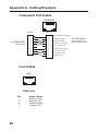
Appendix A - Cabling Diagrams
Command Port Cable
COMMAND
12345678
PIN NO.
To COMMAND
Port Jack
PIN NO.
1
20
Data Terminal Ready (DTR)
2
2
Transmit Data (BA)
To DTE Device
3
3
Receive Data (BB)
4
4
Request To Send (RTS)
(Terminal Device; e.g.,
ASCII Terminal or PC)
5
5
Clear To Send (CTS)
6
6
Data Set Ready (DSR)
7
7
Signal Ground (AB)
8
Carrier Detect (CD)
1
Chassis Ground
8
.
Line Cable
LINE
12345678
RJ48 Jack
Pin
1
2
4
5
50
Signal Name
Receive Ring
Receive Tip
Transmit Ring
Transmit Tip
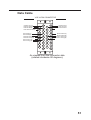
Data Cable
V.35 34-PIN CONNECTOR
Chassis Ground
Request To Send
Data Set Ready
Data Terminal Ready
Send Data (A)
Send Data (B)
Terminal Timing (A)
Terminal Timing (B)
Send Timing (A)
Send Timing (B)
C
H
M
S
W
AA
EE
KK
A
E
K
P
U
Y
CC
HH
MM
D
J
N
T
X
BB
FF
LL
B
F
Signal Ground
Clear To Send
Data Carrier Detect
L
R
V
Receive Data (A)
Receive Data (B)
Receive Timing (A)
Receive Timing (B)
Z
DD
JJ
NN
As viewed from the connector side
(rotated clockwise 90 degrees).
51
82083200