1
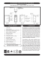
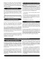
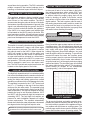
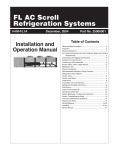
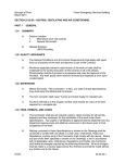
INSTALLATION MANUAL Q95M-200 GAS-FIRED DIRECT VENT MODULATING HOT WATER BOILER DUNKIRK BOILERS 85 Middle Rd. Dunkirk, NY 14048 www.dunkirk.com An ISO 9001-2000 Certified Company P/N 240006103D, Rev. 1.1 [04/06] GAS-FIRED DIRECT VENT MODULATING HOT WATER BOILER INSTALLATION MANUAL P/N# 240006103D, Rev. 1.1 [04/06] • Printed in USA • Made In USA I - INTRODUCTION TABLE OF CONTENTS I II III IV V VI VII VIII IX X XI XII XIII XIV Introduction.......................................... Safety Symbols.................................... Rules for Safe Installation and Operation Boiler Ratings and Capacities............. Before Installing The Boiler.................. Placing The Boiler................................ Near Boiler Piping................................ Combustion Air and Vent Pipe............. Gas Supply Piping............................... Electrical Wiring................................... Controls and Accessories.................... Maintenance and Cleaning.................. Boiler Wire Diagram............................ Piping and Wiring Appendix................. This appliance is a gas-fired direct vent modulating cast aluminum hot water boiler. A revolutionary cast aluminum monoblock heat exchanger means better heat transfer and thermal storage than similarly sized cast iron boilers, which results in higher efficiency. The heating system water absorbs large amounts of heat from the cast aluminum heat exchanger, cooling the flue gases and causing condensation. Sealed combustion, premix gas burner, and low flame temperature means drastically reduced CO and NOx emissions, which contribute to a cleaner and healthier environment. 3 4 4 5 6 9 10 11 13 15 16 18 21 22 This appliance, unlike normal residential atmospheric and induced draft units, takes its combustion air directly from the outdoors (sealed combustion) and does not compete with building occupants for fresh air. Sealed combustion (also known as “direct vent”) is the safest and best way to obtain plenty of clean combustion air. The forced draft fan draws in the outside combustion air to mix with gas, which flows into the pre-mix burner and combusts. The fan then forces the resulting flue gases from the boiler unit and provides a positive removal of the flue gases from the building through inexpensive and readily available PVC and CPVC pipes. Keep this manual near boiler and retain for future reference. 3 II - SAFETY SYMBOLS AND WARNINGS The following defined symbols are used throughout this manual to notify the reader of potential hazards of varying risk levels. ! DANGER ! ! WARNING ! Indicates a potentially hazardous situation which, if not avoided, may result in minor or moderate injury. It may also be used to alert against unsafe practices. Indicates an imminently hazardous situation which, if not avoided, will result in death or serious injury. ! CAUTION ! IMPORTANT: Read the following instructions completely before installing!! Indicates a potentially hazardous situation which, if not avoided, could result in death or serious injury. III. RULES FOR SAFE INSTALLATION AND OPERATION ! WARNING 2. Before servicing the boiler, allow it to cool. Always shut off any electricity and gas supply connected to the boiler prior to servicing. ! This appliance has been equipped for residential installations. If used for commercial applications, any and all additional code requirements must be adhered to for installation. This may require additional controls, including but not limited to an external water cut off, a manual reset high temperature limit, and wiring and/or piping modifications. The manufacturer is not responsible for any field installation changes made to a boiler installation which are not described or acknowledged in this manual. 3. Inspect gas line for leaks. 4. Be certain gas input rate is correct. Overfiring may result in early failure of the boiler components. This may cause dangerous operation. Underfiring may result in too much air for the pre-mix burner causing poor or loss of combustion. 5. Never vent the products of combustion from this boiler to an enclosed space. Always vent to the outdoors. Never vent to another room or to inside a building. IMPORTANT: Failure to follow these instructions could cause a malfunction of the boiler and result in death, serious bodily injury, and/or property damage. For assistance or additional information, consult a qualified installer, service agency, or the gas supplier. ! WARNING 6. Be sure there is adequate outdoor air supply to boiler for complete combustion. 7. Follow a regular service and maintenance schedule for efficient and safe operation. ! 8. Keep boiler area clean of debris and free of combustible and flammable materials. This boiler contains ceramic fiber materials. Use care when handling these materials per the instructions specified under “Modulating Burner” in Section XI of this manual. 9. Proper through-the-wall or through-the-roof combustion venting shall be in accordance with the materials and methods described in this manual. Installation must comply with local codes. 1. Check all applicable state and local building codes and utility company requirements before installation. This installation must conform with these requirements in their entirety. In the absence of these codes, use NFPA installation codes and good industry practice. 10. This boiler and related hot water heating systems are not do-it-yourself items. They must be installed and serviced by qualified professionals.Rat- 4 IV - BOILER RATINGS AND CAPACITIES TABLE 1: SEA LEVEL RATINGS - NATURAL AND PROPANE GASES Boiler Input Rate (MBH)(1) Heating Capacity (MBH)(1)(2) Net I=B=R Rating (MBH)(1) High Fire 200 190 165 Low Fire 80 76 66 (1) (2) AFUE(2) Flue Diameter Shipping Wt. 95% 2” CPVC & 3” PVC 284 lbs. 1 MBH = 1,000 Btuh (British Thermal Units Per Hour) Heating Capacity and AFUE (Annual Fuel Utilization Efficiency) are based on DOE (Department of Energy) test procedures. TABLE 2: 95M-200 HIGH ALTITUDE DERATE CHART Boiler Input Rate (MBH) 3,000 4,000 5,000 Altitude (In Feet) 6,000 7,000 8,000 9,000 10,000 High Fire 196 192 188 184 181 177 174 170 Low Fire 78.4 76.8 75.3 73.8 72.3 70.9 69.5 68.1 ings above are for sea level applications. The boiler automatically derates input at a rate of 2% for every 1000 feet above an elevation of 2000 feet (see Table 2). The boiler will also derate relative to the calorific value of the gas being used. Use the formula specified in “Measure The Natural Gas Input Rate” in Section VII of the Control Manual and Operating Instructions (P/N# 240006104) to determine the proper rate due to derated gas. No alterations to the boiler are required for altitudes above sea level. The Heating Capacity indicates the amount of heat available after subtracting the losses up the stack. Most of this heat is available to heat water. A small portion is heat loss from the jacket and surfaces of the boiler, and it is assumed that this heat stays in the structure. The Net I=B=R Rating represents the portion of the remaining heat that can be applied to heat the radiation or terminal units (i.e., finned tube baseboard, cast iron radiators, radiant floor, etc.) The difference between the Heating Capacity and the Net I=B=R Rating, called the piping and pickup allowance, establishes a reserve for heating the volume of water in the system and offsetting heat losses from the piping. The Net I=B=R Ratings shown are based on a piping and pickup factor of 1.15 in accordance with the I=B=R Standard as published by the Hydronics Institute. The Net I=B=R Rating of the boiler selected should be greater than or equal to the calculated peak heating load (heat loss) for the building or area(s) served by the boiler and associated hot water heating systems. The manufacturer should be consulted before selecting a boiler for installations having unusual piping and pickup requirements. These low pressure gas-fired hot water boilers are design certified by CSA International, for use with natural and propane gases. The boilers are constructed and hydrostatically tested for a maximum working pressure of 50 PSIG (pounds per square inch gauge) in accordance with ASME (American Society of Mechanical Engineers) Boiler and Pressure Vessel Code Section IV Standards for heating boilers. The Boilers are certified in accordance with ANSI (American National Standards Institute) Z21.13 standards as gas-fired, direct vent, condensing, hot water boilers. V - BEFORE INSTALLING THE BOILER Canada - Installation shall be in accordance with CSA-B149.1 and .2 installation codes. Review the following before installing the boiler. CODES Where required by the authority having jurisdiction, the installation must conform to the ASME Safety Code for Controls and Safety Devices for Automatically Fired Boilers, No.CSD-1. This boiler product is a gas-fired, direct vent, condensing boiler and must be installed in accordance with all applicable federal, state and local building codes including, but not limited to the following: The installation must conform to the requirements of the authority having jurisdiction or, in the absence of such requirements, to the National Fuel Gas Code, ANSI Z223.1 - latest revision. United States - Installation shall conform with National Fuel Gas Code (NFPA-54/ANSI Z223.1latest edition) 5 Installers - Follow local regulations with respect to installation of Carbon Monoxide Detectors. Follow maintenance recommendations in this manual. LOCATING THE BOILER 1. Select a location which is level, central to the piping systems served and as close to the vent and air intake terminals as possible. BOILER SIZING • • 2. Accessibility clearances, if more stringent (i.e. larger clearances) than required fire protection clearances, must be used for the boiler installation. Accessibility clearances may be achieved with the use of removable walls or partitions. Check to be sure you have selected the boiler with the proper capacity before continuing the installation. The I=B=R Rating of the boiler selected should be greater than or equal to the calculated peak heating load (heat loss) for the building or area(s) served by the boiler and associated hot water heating systems. See “Table 1: Sea Level Ratings - Natural and Propane Gases” in Section IV of this manual. 3. The boiler is approved for installation in closets and on combustible floors. This boiler shall NOT be installed on carpeting. 4. The clearances shown in Table 3 below indicate required clearances per CSA listing. Heat loss calculations should be based on approved industry methods. TABLE 3: BOILER CLEARANCES* CONSIDERATIONS FOR BOILER LOCATION Dimension Before selecting a location for the boiler, the following should be considered. Each boiler considered for installation must be: • • Supplied with the correct type of gas (natural gas or propane). Connected to a suitable combustion air intake piping system to supply the correct amounts of fresh (outdoor) air for combustion (15’ minimum length/60’ maximum length). • Connected to a suitable venting system to remove the hazardous products of gas combustion (15’ minimum length/60’ maximum length). • Connected to a suitable hot water heating system. • Supplied with a suitable electrical supply for all boiler motors and controls. • Connected to a properly located thermostat or operating control (not included with boiler). • Placed on level surface (must NOT be installed on carpeting). • Condensate drain line must be pitched down to floor drain or external condensate pump with reservoir at ¼” per foot (wood frame or blocks may be used to raise boiler). Combustible Accessibility/ Service Construction Cleaning Top 1” 8” 8” Left Side 1” 24” 24” Right Side 1” - - Base 1” - - Front 0 24” 24” Back 6” - - Intake/Vent Piping 0 - - Near Boiler Hot Water Piping 1” - - * All distances measured from the cabinet of the boiler. A minimum 1” clearance must be maintained between combustible construction and each of the right, top and back surfaces of the boiler. Allow at least 24” at the front and left side and 8”at the top for servicing. No combustible clearances are required to venting or combustion air intake piping. 5. Equipment shall be installed in a location which facilitates the operation of venting and combustion air intake piping systems as described in this manual. 6. Advise owner of boiler to keep venting and combustion air intake passages free of obstructions. Both the venting and combustion air intake piping systems connected to the outdoors must permit flow through the piping systems without restrictions for the boiler to operate. 7. The boiler shall be installed such that the automatic gas ignition system components are protected from water (dripping, spraying, rain, etc.) during 6 operation and service (circulator replacement, control replacement, etc.). This boiler requires a dedicated direct vent system. In a direct vent system, all air for combustion is taken directly from outside atmosphere, and all flue products are discharged to outside atmosphere. 8. The boiler must be located where ambient room temperatures (minimum possible temperatures where boiler is installed assuming boiler is not in operation and therefore contributes no heat to the space) are always at or above 32°F to prevent freezing of liquid condensate. Combustion air and vent pipe connections must terminate together in the same atmospheric pressure zone, either through the roof or sidewall (roof termination preferred). See Figures 1 and 2 for required clearances. COMBUSTION AIR AND VENT PIPE REQUIREMENTS If the concentric vent termination is being used, refer to Figure 3 for proper setup. Figure 1 - Roof Vent/Intake Terminations Figure 3 - Concentric Vent Terminations 15'' MAXIMUM 1" MAXIMUM 3'' MAXIMUM SEPARATION ROOF OVERHANG 12" MINIMUM 12'' MIMIMUM 8" MINIMUM VERTICAL SEPARATION BETWEEN COMBUSTION AIR INTAKE AND VENT 12" MINIMUM MAINTAIN 12" MINIMUM CLEARANCE ABOVE HIGHEST ANTICIPATED SNOW LEVEL COMBUSTION AIR VENT MAINTAIN 12" IN. CLEARANCE ABOVE HIGHEST ANTICIPATED SNOW LEVEL OR GRADE COMBUSTION AIR Figure 2 - Sidewall Vent/Intake Terminations OVERHANG 12" SEPARATION BETWEEN BOTTOM OF COMBUSTION AIR INTAKE AND BOTTOM OF VENT 12" MINIMUM VENT ! 12" MINIMUM 12" MINIMUM 90° ! 3" MAXIMUM SEPARATION 15" MAXIMUM LESS THAN 12" CLEARANCE When vent pipe is exposed to temperatures below freezing, such as when it passes through an unheated space or when a chimney is used as a chaseway, vent pipe must be insulated with ½”Armaflex or equivalent. In extremely cold climate areas, use ¾”Armaflex or equivalent. • Combustion air must be clean outdoor air. Combustion air must not be taken from inside the structure because that air is frequently contaminated by halogens, which include fluorides, chlorides, phos- 12" MINIMUM VENT BRACKET 3" MAXIMUM SEPARATION ! • OVERHANG 90° WARNING Failure to follow these warnings could result in fire, property damage, personal injury, or death. 18" MAXIMUM 12" MINIMUM ! Keep boiler area clean of debris and free of flammable and combustible materials, vapors, and liquids. MAINTAIN 12" MINIMUM CLEARANCE ABOVE HIGHEST ANTICIPATED SNOW LEVEL OR GRADE 12" MINIMUM CAUTION 12" SEPARATION BETWEEN BOTTOM OF COMBUSTION AIR INTAKE AND BOTTOM OF VENT MAINTAIN 12" MINIMUM CLEARANCE ABOVE HIGHEST ANTICIPATED SNOW LEVEL OR GRADE 18" MAXIMUM 12" OR MORE CLEARANCE (Continued on next page) 7 ! WARNING ! Figure 5 - Concentric Vent Roof Installation (Continued from previous page) phates, bromides and iodides. These elements are found in aerosols, detergents, bleaches, cleaning solvents, salts, air fresheners, paints, adhesives, and other household products. • Locate combustion air inlet as far away as possible from swimming pool and swimming pool pump house. All combustion air and vent pipes must be airtight and watertight. Combustion air and vent piping must also terminate exactly as shown in Figures 1 and 2. If a concentric vent termination is being used, refer to Figures 3 through 5 for proper setup. • Vent connections serving appliances vented by natural draft shall not be connected into any portion of mechanical draft systems operating under positive pressure. • Solvent cements are combustible. Keep away from heat, sparks, or open flame. Use only in well ventilated areas. Avoid breathing in vapor or allowing contact with skin or eyes. CONDENSATE DRAIN REQUIREMENTS At the rear of the unit a ½” PVC pipe nipple with NPT threads is provided for the attachment of the condensate drain line. Attach the ½” PVC tee in the parts bag to act as a vent as shown. Attach ½” PVC from this point to either a drain or an external condensate pump (not furnished). If the drain level is above the condensate trap, a condensate pump must be used. The condensate pump must be designed for a flue gas condensate application. The condensate drain line must be pitched down to the floor at a minimum of ¼” per foot and must be routed within the conditioned space to avoid freezing of condensate and blockage of the drain line. If the unit will be started immediately upon completion of installation, prime trap by filling with water until water is seen at the vent. Figure 4 - Concentric Vent w/Dimensions NOTES: 8 1. Condensate trap is integral to the boiler. 2. Wood frame or blocks may be used to raise the boiler to maintain drain pitch or to be above external condensate pump reservoir. 3. There is a 115 volt AC receptacle provided on the control panel to provide power for an external condensate pump (if needed). in which the appliances remaining connected to the common venting system are located and other spaces of the building. Turn on clothes dryer and any appliance not connected to the common venting system. Turn on any exhaust fans, such as range hoods and bathroom exhaust, so they will operate at maximum speed. Do not operate a summer exhaust fan. Close fire dampers. FOUNDATION REQUIREMENTS Boiler must be placed on level surface. Boiler is NOT to be installed on carpeting. NOTES: 1. If boiler is not level condensate drain lines will not function properly. Adjustable feet are located on the boiler to make up for minor surface irregularities or tilt. 2. Wood frame or blocks may be used to raise boiler to maintain drain pitch or to be above external condensate pump reservoir. 4. Place in operation the appliance being inspected. Follow the lighting instructions. Adjust thermostat so appliances will operate continuously. REMOVAL OF EXISTING BOILER FROM COMMON VENT SYSTEM 5. Test for spillage at the draft hood relief opening after 5 minutes of main burner operation. Use the flame of a match or candle, or the smoke from a cigarette, cigar or pipe. When an existing boiler is removed from a common venting system, the common venting system is likely to be too large for proper venting of the appliances remaining connected to it. At the time of removal of an existing boiler, the following steps shall be followed with each appliance remaining connected to the common venting system placed in operation, while the other appliances remaining connected to the common venting system are not in operation. 6. After it has been determined that each appliance remaining connected to the common venting system properly vents when tested as outlined above, return doors, windows, exhaust fans and any other gas-burning appliance to their previous condition of use. 7. Any improper operation of the common venting system should be corrected so the installation conforms with the National Fuel Code, NFPA-54/ANSI -Z223.1-latest revision, or section 5 of CSA-B149 for Canadian standards. When resizing any portion of the common venting system, the common venting system should be resized to approach the minimum size as determined using the appropriate tables in part 11 in the National Fuel Gas Code, NFPA-54/ANSIZ223.1-latest revision, or section 5 of CSA-B149 for Canadian standards. 1. Seal any unused openings in the common venting system. 2. Visually inspect the venting system for proper size and horizontal pitch and determine there is no blockage or restrictions, leakage, corrosion and other deficiencies which could cause an unsafe condition. 3. When it is practical, close all building doors and windows and all doors between the space VI - PLACING THE BOILER ! WARNING ! may be moved into position with an appliance dolly or 2-wheel hand truck. The dolly or hand truck should be inserted under the right hand side of the boiler. It is possible to slide the boiler for a short distance on a smooth floor or surface. The boiler must be located on a surface that can support the weight of the installed boiler. The boiler should be placed to provide the most direct connections to the combustion air, vent and system piping as possible. NOTE: Refer to “Locating The Boiler” in Section V of this manual for required clearances for servicing and maintenance. Place crated boiler as close to selected location as possible and uncrate boiler. The uncrated boiler 9 VII - NEAR BOILER PIPING IMPORTANT: For piping examples using the Gas-Fired Direct Vent Modulating Hot Water Boiler, see the Piping Appendix in Section XIV of this manual. ! CAUTION ! Copper supply and return piping must NOT be installed directly into aluminum boiler section castings due to galvanic corrosion between dissimilar metals. Iron or steel bushings or pipe nipples should be used between copper system piping and boiler to make final connection to boiler. Also, the use of dielectric unions is acceptable. The packaged boiler is furnished with iron piping where necessary for the supply and return connections. ter supply is from a well or pump, a sand strainer should be installed at the pump. Figure 6 - Diaphragm Type Expansion Tank Piping When the installation of the boiler is for a new heating system, first install all of the radiation units (panels, radiators, baseboard, or tubing) and the supply and return mains. After all heating system piping and components have been installed, make final connection of the system piping to the boiler. A hot water boiler installed above radiation level must be equipped with a low water cut off device. A periodic inspection is necessary, as is flushing of float type devices, per low water cut off manufacturers specific instructions. This boiler is factory equipped with a manual reset probe-type low water cut off. PRESSURE RELIEF VALVE / TEMPERATURE PRESSURE GAUGE Figure 7 - Relief Valve Discharge Piping EXPANSION TANK AND MAKE-UP WATER ! CAUTION ! Non-potable water only piped directly to boiler. Determine required system fill pressure, system design temperature, and system water content. Boiler contains 2.6 gallons (US). Size expansion tank accordingly. Consult expansion tank manufacturer for proper sizing information. Connect properly sized expansion tank (not furnished) as shown in Figure 6 for diaphragm type expansion tank. For diaphragm type expansion tanks, adjust the tank air pressure to match the system fill pressure. Install air vent (furnished) as shown for diaphragm type expansion tank system only. Install make-up water connections as shown and per local codes. If a pressure reducing valve is used, adjust to match the system fill pressure. In connecting the cold make-up water supply to the boiler, make sure that clean water supply is available. When the wa- The boiler is furnished with a relief valve in the boiler parts bag. Provide ¾” piping from the supplied relief valve to a local floor drain, but leave an air gap between piping and drain. No shutoff of any description shall be placed between safety relief valve and the boiler, or on the discharge pipes 10 between such safety valve and the atmosphere. Installation of the safety relief valve shall conform to ANSI/ASME Boiler and Pressure Vessel Code, Section IV. The manufacturer is not responsible for any water damage. SUPPLY AND RETURN LINES The packaged boiler unit is set up to receive 1¼” NPT return piping from the rear of the unit with an option for left or right return connections. 1¼” NPT supply piping exits the boiler jacket at the top of the unit. FILLING CONDENSATE TRAP WITH WATER IMPORTANT: On initial start up the condensate trap must be manually filled with water. The following are the steps required to initially fill the condensate trap for start up, these steps are only required at the initial start up or if maintenance requires draining of the condensate trap: 1. Pour about 1 cup of cold tap water into the vent drain line. 2. Excess water should go through the overflow and out through the condensate drain line. Verify proper operation of the drain line (or external condensate pump if used). NOTE: Circulator pump and isolation valves are furnished within a carton inside the boiler cabinet and can be installed at the installer preferred location. CONDENSATE DRAIN PIPING 3. Reinstall the vent drain line. The condensate trap is integral to the boiler. Provide ½” pipe and fittings for PVC condensate drain line. Condensate drain line to be pitched down to floor drain at a minimum of ¼” per foot. The ½” diameter schedule 40 PVC condensate drain piping and pipe fittings must conform to ANSI standards and ASTM D1785. Schedule 40 PVC cement and primer must conform to ASTM D2564. In Canada, use CSA or ULC certified schedule 40 PVC drain pipe and cement. A condensate pump with a reservoir (not furnished) may be used to remove condensate to a drain line (sanitary line) above boiler if a floor drain is not available or is inaccessible. CHILLED WATER PIPING The boiler, when used in connection with a refrigeration system, must be installed so the chiller medium is piped in parallel with the boiler with appropriate valves to prevent the chilled medium from entering the boiler. The boiler piping system of a hot water boiler connected to heating coils located in air handling units where they may be exposed to refrigerated air circulation must be equipped with flow control valves or other automatic means to prevent gravity circulation of the boiler water during cooling cycle. VIII - COMBUSTION AIR AND VENT PIPE CONNECTIONS AND TERMINATION For boilers connected to gas vents or chimneys, vent installations shall be in accordance with Part 7, Venting of Equipment, of the National Fuel Gas Code, ANSI Z223.1-latest revision, CSA-B149.1 and B149.2, and applicable provisions of the local building codes. These boilers require a dedicated direct vent system. All air for combustion is taken directly from outdoors through the combustion air intake pipe. All flue products are discharged to the outdoors through the vent pipe. Insulate lengths of combustion pipe in unconditioned areas. 1. See Figures 1 through 5 for combustion air and vent pipe roof and sidewall termination (roof termination is preferred). Combustion air and vent pipes must terminate together in same atmospheric pressure zone as shown. Construction through which vent and air intake pipes may be installed is a maximum 24” and a minimum ¼” thickness. Provisions for combustion and ventilation air must be in accordance with Section 5.3, Air For Combustion and Ventilation, of the National Fuel Gas Code, ANSI Z223.1-latest revision, CSA-B149.1 and B149.2, or applicable provisions of the local building code. 11 2. Combustion air and vent pipe fittings must conform to American National Standards Institute (ANSI) standards and American Society for Testing and Materials (ASTM) standards D1784 (schedule-40 CPVC), D1785 (schedule40 PVC), D2665 (PVC-DWV), D2241 (SDR-21 and SDR-26 PVC), D2661 (ABS-DWV), or F628 (schedule-40 ABS). Pipe cement and primer must conform to ASTM standards D2564 (PVC) or D2235 (ABS). 1. Combustion air piping to be pitched back to boiler at minimum ¼” per foot from vent terminals so that all moisture in vent piping drains to boiler. Pipes must be pitched continuously with no sags or low spots where moisture can accumulate and block the flow of flue gas. Combustion air and vent pipes must be airtight and watertight. 2. Consideration for the following should be used when determining an appropriate location for termination of combustion air and vent piping: In Canada construct all combustion air and vent pipes for this unit of CSA or ULC certified schedule-40 CPVC, schedule-40 PVC, PVC-DWV or ABS-DWV pipe and pipe cement. SDR pipe is NOT approved in Canada. 3. Combustion air and vent pipe connections on boiler are 2” but must increase to 3”. Due to potential for flue gas temperatures above 155°F, the first 30” of supplied vent pipe is CPVC while the remaining vent pipe can be PVC. Any replacement of the first 30” of vent pipe must be made with CPVC. NOTE: The exhaust transition from 2” pipe to 3” pipe must be made in a vertical run. Transition pieces are not included. (See Figure 8 for details.) COMBUSTION AND VENT PIPING LENGTH 3” Pipe Min. Venting 15 ft. equivalent length 3” Pipe Max. Venting 60 ft. equivalent length The length of pipe is counted from the end of the supplied 2” CPVC pipe exiting the boiler. The combustion air supply pipe must terminate at the same location as the exhaust pipe. Reduce the maximum vent length by 5’ per each 90° elbow. Figure 8 - Combustion Air and Vent Piping • Comply with all clearances required. • Termination should be positioned where vent vapors will not damage plants/shrubs or air conditioning equipment. • Termination should be positioned so that it will not be effected by wind eddy, air born leaves, snow, or recirculated flue gases. • Termination should be positioned where it will not be subjected to potential damage by foreign objects, such as stones, balls, etc. • Termination should be positioned where vent vapors are not objectionable. • Put vent on a wall away from the prevailing winter wind. Locate or guard the vent to prevent accidental contact with people or pets. • Terminate the vent above normal snowline. Avoid locations where snow may drift and block the vent. Ice or snow may cause the boiler to shut down if the vent becomes obstructed. • Under certain conditions, flue gas will condense, forming moisture, and may be corrosive. In such cases, steps should be taken to prevent building materials at the vent from being damaged by exhaust of flue gas. 3. The venting system shall terminate at least 3’ above any forced air inlet (except boiler’s combustion air inlet) within 10’. The venting system shall terminate at least 12” from any air opening into any building. The bottom of the vent shall be located at least 12” above grade. Termination of the vent shall be not less than 7’ above an adjacent public walkway. The vent terminal shall not be installed closer than 3’ from the inside corner of an “L” shaped structure. Termination of the vent should be kept at least 3’ away from vegetation. The venting system shall terminate at least 4’ horizontally from, and in no case above 12 or below, electric meters, gas meters, regulators, and relief equipment. 7. After pipes have been cut and pre-assembled, apply cement primer to pipe fitting socket and end of pipe to insertion mark. Quickly apply approved cement to end of pipe and fitting socket (over primer). Apply cement in light, uniform coat on the inside of socket to prevent buildup of excess cement. Apply second coat. If multiple terminations are used, there must be a minimum of 12” between the exhaust of one termination and the air intake of the next termination. See Figures 1-3 for illustrations. NOTE: Primer and cement will discolor jacket. Take precautions to protect jacket while cementing vent pipe. INSTALLATION IMPORTANT: When transitioning from CPVC to PVC it is recommended to use Weld-On CPVC 724 or other cement approved for CPVC and PVC. 8. While cement is still wet, insert pipe into socket with a ¼ turn twist. Be sure pipe is fully inserted into fitting socket. 1. Attach combustion air intake piping to supplied 2” PVC Intake Connector. Attach vent piping to furnished 2” CPVC vent pipe. 9. Wipe excess cement from joint. A continuous bead of cement will be visible around perimeter of a properly made joint. NOTE: All pipe joints are to be water tight. 10. Handle pipe joint carefully until cement sets. 2. Working from the boiler to the outside, cut pipe to required length(s). 11. Support combustion air and vent piping a minimum of every 5’ using pre-formed metal hanging straps. Support combustion air and vent piping so no weight is resting on the boiler jacket. Do not rigidly support pipes. Allow movement due to expansion and contraction. 3. Deburr inside and outside of pipe. 4. Chamfer outside edge of pipe for better distribution of primer and cement. 12. Slope combustion air and vent pipes toward boiler a minimum of ¼” per linear foot with no sags between hangers. 5. Clean and dry all surfaces to be joined. 6. Check dry fit of pipe and mark insertion depth on pipe. 13. Use appropriate methods to seal openings where vent and combustion air pipes pass through roof or side wall. NOTE: It is recommended that all pipes be cut, prepared, and pre-assembled before permanently cementing any joint. IX - GAS SUPPLY PIPING CHECK GAS SUPPLY TABLE 4: GAS PIPING SIZES Natural Gas The gas pipe to your boiler must be the correct size for the length of run and for the total BTU per hour input of all gas utilization equipment connected to it. See Table 4 at right for proper size. Be sure your gas line complies with local codes and gas company requirements. Pipe Length The boiler and its individual shutoff valve must be disconnected from the gas supply piping system during any pressure testing of that system at test pressures in excess of ½ psig (3.5kPa). Pipe Capacity - BTU/Hr. Input Includes Fittings ½” ¾” 1” 1¼” 20’ 92,000 190,000 350,000 625,000 40’ 63,000 130,000 245,000 445,000 60’ 50,000 105,000 195,000 365,000 LP Gas Pipe Length The boiler must be isolated from the gas supply piping system by closing its individual manual shutoff valve during any pressure testing of the gas supply piping system at test pressures equal to or greater than ½ psig (3.5kPa). Pipe Capacity - BTU/Hr. Input Includes Fittings Copper Tubing (O.D.) Iron Pipe ⅝” ¾” ½” ¾” 20’ 131,000 216,000 189,000 393,000 40’ 90,000 145,000 129,000 267,000 60’ 72,000 121,000 103,000 217,000 The length of pipe or tubing should be measured from the gas meter or propane second stage regulator. 13 In order for proper operation of the boiler, it is recommended that the line pressure be within the minimum and maximum values in Table 5. 2. Use pipe joint compound suitable for liquefied petroleum gas on male threads only. 3. Use ground joint unions. TABLE 5: GAS SUPPLY PRESSURE Natural Gas 4” min. w.c. 10” max. w.c. LP Gas 10” min. w.c. 14” max. w.c. 4. Install a sediment trap upstream of gas controls. Please check line pressure while unit is running. 5. Use two pipe wrenches when making the connection to the gas valve to keep it from turning. CONNECTING THE GAS PIPING Refer to Figure 9 for the general layout at the boiler, which shows the basic fittings you will need. As shipped, the gas line enters the boiler through the rear but, as an option, it can be routed through either the right or left side panel. 6. Install a manual shutoff valve in the vertical pipe about 5’ above floor outside the boiler jacket in addition to the shutoff valve supplied with the boiler. 7. Tighten all joints securely. Figure 9 - Gas Piping 8. Propane gas connections should only be made by a licensed propane installer. 9. Two stage regulation should be used by the propane installer. 10. Propane gas piping should be checked out by the propane installer. GAS CONNECTION The boiler is equipped with a ½” NPT connection on the gas valve for supply piping and ½” NPT ball valve for manual shut off. The following rules apply for boiler piping: 1. Use only those piping materials and joining methods listed as acceptable by the authority having jurisdiction, or in the absence of such requirements, by the National Fuel Gas Code, ANSI Z223.1- latest revision. In Canada, follow the CAN/CGA B149.1 and .2 Installation Codes for Gas Burning Appliances and Equipment. 11. In addition to the components supplied with the boiler, it is recommended to use a ½” union and ball valve suitable for natural and propane gas upstream of the furnished ½” NPT ball valve to facilitate service on the unit. CHECKING THE GAS PIPING After all connections have been made, check immediately for leaks. Open the manual shutoff valve. Test for leaks by applying soap suds (or a liquid detergent) to each joint. Bubbles forming indicate leak. Correct even the smallest leak at once. ! WARNING ! Never use a match or open flame to test for leaks!! 14 X - ELECTRICAL WIRING IMPORTANT: Wiring diagrams for the Gas-Fired Direct Vent Modulating Hot Water Boiler can be found in Section XIII of this manual. ! WARNING ! 2. Route all low voltage wires through grommeted opening on the right jacket panel. For your safety, turn off electrical power supply at service panel before making any electrical connections to avoid possible electric shock hazard. Failure to do so can cause severe personal injury or death. THERMOSTAT 1. Connect room thermostat or end switch (isolated contact only) between terminals T1 and T2. IMPORTANT: Wiring must be N.E.C. Class 1. If original boiler wiring must be replaced, use only type 105°C wire or equivalent. Boiler must be electrically grounded as required by National Electrical Code ANSI/NFPA 70 - latest edition. 2. Install thermostat on inside wall away from influences of drafts, hot or cold water pipes, lighting fixtures, televisions, sunrays, or fireplaces. CODES A. If connected directly to boiler, set for 0.1 amps. 3. Thermostat anticipator (if applicable): Installations must comply with National Electrical Code, any other national, state, provincial, or local codes or regulations, and, in Canada, with CSA C22.1 Canadian Electrical Code (Part 1) and any local codes. B. If connected to relays or other devices, set to match total electrical power requirements of connected devices. See device manufacturers’ specifications and thermostat instructions for details. LINE VOLTAGE CONNECTIONS 1. Connect 120 VAC power wiring to line voltage terminal strip on boiler control panel. 2. Provide and install a fused disconnect or service switch (15 amp recommended) as required by code. 3. Boiler circulator is shipped loose. Wire boiler circulator as shown in wire diagram label on boiler side panel. 4. When connecting a DHW circulator, connect wiring to line voltage terminal strip on boiler control panel. 5. Route all wires and conduits to the openings in the right jacket panel. LOW VOLTAGE CONNECTIONS 1. Connect low voltage wiring to low voltage terminal strip as shown in the boiler wiring diagram. OUTDOOR TEMPERATURE SENSOR 1. Connect outdoor temperature sensor between terminals A1 and A2 to enable outdoor reset operation of the boiler. If fixed temperature operation is required, do not install outdoor sensor. 2. Mount sensor on exterior wall, shielded from direct sunlight or flow of heat or cooling from other sources. 3. If desired, install a summer/winter switch across terminals A1 and A2. When the switch is closed, the boiler (space heating) circulator is disabled. 4. Route sensor wires through the holes provided on the right jacket panel of the boiler. DHW AQUASTAT Connect storage indirect water heater (DHW) aquastat between terminals DHW T1 and DHW T2. 15 XI - CONTROLS AND ACCESSORIES This section provides a brief description of the key into the combustion chamber where combustion can controls and accessories found in this boiler. See the begin and then out the exhaust vent where the comRepair Parts Manual (P/N# 240006107) for illustra- bustion products are discharged to the outdoors. The tions and the Control Manual and Operation Instruc- blower is designed to communicate with the modutions (P/N# 240006104) for a detailed sequence of lating control to run at variable speeds dependent operation and troubleshooting procedures. on the heat load experienced by the heating system. The variable speeds create pressures felt by the gas ALUMINUM HEAT EXCHANGER valve and gas/air mixer that dictate how much fuel is introduced to the combustion process. This appliance employs a cast aluminum heat exchanger that features a monoblock design. The GAS CONTROL VALVE monoblock design eliminates the need for mating sections and therefore eliminates leaks between The gas controls in this boiler have been developed sections. Since the heat exchanger is cast of alu- for domestic heating appliances with premix burnminum instead of iron, it has better heat transfer ers and automatic direct burner ignition and are properties which in turn lead to higher efficiency suitable for natural and LP gas. The gas controls and cooler exhaust temperatures. These cooler ex- perform all the functions required to safely regulate haust temperatures create condensation of the flue gas flow to the main burner of the boiler. The gas gas, which would cause corrosion in traditional cast valve is directly connected to the gas/air mixer. iron heat exchangers. GAS/AIR MIXER MAIN POWER SWITCH The venturi design of the gas/air ensures that there This appliance features a main power switch located is always the correct mixture of air and gas. on the display panel. The main power switch is illuminated when it is receiving power and in the ON MODULATING BURNER position. The only time that the switch should not be illuminated once the boiler is ready for use is when This burner is designed to operate over the full range the casting temperature safety switch has been of input for this boiler. The burner can operate under tripped or when the switch is in the OFF position. normal (blue flame) and infrared conditions. ! MODULATING BOILER CONTROL This appliance incorporates an integrated modulating control that senses the load necessary to heat a structure and therefore uses less fuel than a conventional fixed firing rate boiler when there is a lower than peak demand for heat. The control senses the supply water, return water, and outside air temperatures and calculates the load on the system. It then adjusts the firing rate to deliver the amount of heat that is needed at that particular time. WARNING ! The NTC sensors used with this appliance for measuring supply water, return water, and outside air temperature are specially configured to operate with the modulating boiler control. The burner in this unit contains ceramic fibers which can be converted to a cancercausing substance called cristobalite in very high temperature applications. When removing the burner, avoid breathing dust by using a NIOSH (National Institute for Occupational Safety and Health) certified dust respirator and wear long-sleeved, loose fitting clothing, gloves, and eye protection to avoid contact with skin and eyes. In case of contact with skin or eyes, wash or irrigate affected area immediately, then wash potentially contaminated clothing separately and rinse clothes washer thoroughly before reusing. For additional information, see the NIOSH homepage at www.cdc.gov/niosh/homepage.html. MODULATING BLOWER DIRECT SPARK IGNITER The modulating blower provides a means of introducing the gas/air mixture through the burner and This appliance uses a direct spark igniter to ignite the fuel/air mixture in the combustion chamber and NTC SENSORS 16 sense flame during operation. The DSI is a durable, reliable component that resists breakage due to handling or inadvertent impact with other objects. MANUAL RESET LOW WATER CUT OFF This appliance employs a factory installed integral low water cut off (LWCO) that has to be manually reset if there is a low water condition. The LWCO senses water through a probe at the top of the boiler that sends a signal through the water to ground. If the signal is not sensed through the ground, the LWCO enters a lockout mode that disables the appliance. If the LWCO is in normal mode a red indicator light is illuminated on the LWCO panel in the boiler. During a low water condition, the red light goes out and the LWCO and control reset buttons on the display panel must be depressed to reset the LWCO. NORMALLY CLOSED LWCO SWITCH This switch is normally closed and spring loaded so that, when depressed, it opens, and closes again when pressure is removed. The switch is used as the manual reset for the LWCO. When tripped the LWCO will remain in lockout until the water level reaches the probe and the switch is depressed to an open state and then released to a closed state, which sends a signal to the LWCO to resume normal operation. The boiler control reset button must then be pressed to reset from a low water condition. The LWCO switch and control reset button are located on the display panel of the boiler. HIGH LIMIT AQUASTAT CONTROL The high limit aquastat control is a redundant safety limit control that determines the maximum boiler water temperature and also provides a means for protecting the boiler and heating system from unsafe operating conditions which could damage the boiler. The aquastat is mounted in the ½” NPT control well and ¾” x ½” bushing on the top of the front boiler section at the hot water outlet. The aquastat is tied in with the boiler control and is factory set at 200°F water temperature. The high limit setpoint is field adjustable and may be set anywhere between 100°F and 200°F, with the maximum high limit setpoint not exceeding 200°F. The field high limit setpoint adjustment for each installation depends on heating system requirements. The aquastat automatically resets when the boiler water temperature decreases ten degrees below the high limit setpoint value. CASTING TEMPERATURE SAFETY SWITCH In the event of lack of or loss of water in the boiler, the casting temperature safety switch (230°F setpoint) installed on the top of the aluminum boiler section behind the supply piping shuts off the boiler by shutting off power to the boiler control and causes a failure code to be displayed on the digital readout. This fault requires manual reset of the casting temperature safety switch to restart the boiler and the reset to be pressed on the user interface panel. Verify that the boiler is properly filled with water before resetting this switch. ! WARNING ! Never run cold water into a hot, empty boiler. CIRCULATOR PUMP Every forced hot water system requires at least one circulating pump. The circulating pump imparts the necessary energy to move water through the closed loop supply and return piping systems, terminal heating equipment (finned tube radiators, etc.) and back through the boiler for reheating. To provide the required hot water flow rates, the circulator pump must be properly sized to overcome frictional losses (usually measured in feet of water, also referred to as “pump head loss”) of the supply and return piping systems and boiler. The circulator pump is furnished in a carton within the boiler cabinet. The circulator(s) should always be located on the downstream (“pumping away”) side of the expansion tank. AIR PROVING BLOCKED VENT SAFETY ASSEMBLY The air proving blocked vent safety assembly incorporates two pressure switches that are wired in series to discontinue operation of the appliance if there is a problem with the blower or venting system. The NOTE: Boiler operating temperature (temperature curve) is normally open switch closes upon the initiation of the calculated and set in the parameters of the boiler control. blower and functions as an air proving switch. The 17 normally closed switch opens if there is a blockage in the combustion air intake or exhaust vent pipes. DRAIN VALVE The manual drain valve provides a means of draining the water in the heating system, including the boiler and hot water supply and return piping systems installed above the drain valve. This drain valve is installed in the return piping at the bottom front of the boiler section. Any piping installed below the elevation of this drain valve will require additional drain valves to be installed at low points in the piping systems in order to drain the entire system. ASME RATED PRESSURE RELIEF VALVE Each boiler must have a properly sized and installed American Society of Mechanical Engineers rated pressure relief valve. Water expands as it is heated by the burner/boiler sections. If there is no place for the water to expand its volume, (i.e., a properly sized and properly functioning expansion tank) pressure on the inside of the boiler and heating system will increase. The furnished relief valve will automatically open at 30 psig pressure to relieve the strain on the boiler and heating system from the increasing pressure. The pressure relief valve discharge must be piped with the same size pipe as the valve discharge opening to an open drain, tub or sink, or other suitable drainage point not subject to freezing, in accordance with ASME specifications. Failure to provide the pressure relief valve with piping as herein described may cause water damage and/or serious bodily injury. The boiler manufacturer is not responsible for any water damage or personal injury. EXTERNAL CONDENSATE PUMP (OPTIONAL) For installations where there is no floor drain or other appropriate drainage receptacle available to receive condensate from the boiler, an external float activated condensate pump with integral sump is required. The condensate pump can be piped to a remote tie in point to a sanitary sewer system. For this application, the boiler must be installed so that proper pitch of piping to the external condensate reservoir (sump) can be accomplished. Use wood frame or blocks to raise boiler as required for proper installation. CONCENTRIC VENT/AIR INTAKE TERMINATION (OPTIONAL) The optional concentric vent/air intake termination utilizes a single opening per each appliance through the wall or roof of a structure. XII - MAINTENANCE AND CLEANING NOTE: Maintenance as outlined below can be performed by the owner unless otherwise noted. The acidic nature of flue gases condensing on the aluminum boiler sections will cause the formation of aluminum oxide. This oxide formation is normal, is generally uniform throughout the boiler sections, and represents a negligible mass of aluminum that is consumed by oxidation during the life of the boiler. If left unchecked, this buildup may eventually cause blockage of the flue gas passages in the boiler sections, reducing efficiency, and ultimately shutting down the boiler due to lack of combustion air flow. Regular service and maintenance by a qualified service agency must be performed at least once every 12 months to assure safe, trouble free operation and maximum efficiency. BEGINNING OF EACH HEATING SEASON 1. Schedule an annual service call by a qualified service agency which includes: 18 • Examining flue passages between boiler sections, burner, and condensate lines, and cleaning (if necessary) by following the instructions in “Annual Examination and Cleaning of Boiler Components” in this section. • Visually inspecting the venting and air intake system for proper operation, immediately repairing or replacing any sign of deterioration or leakage, and insuring proper reassembly and resealing of the system. • Checking for and removing any obstruction to the flow of combustion air or venting of flue gases. • Following the instructions in Sections V and VII of the Control Manual and Operating Instructions (P/N# 240006104), “Putting The Boiler In Operation” and “Checkout Procedures And Adjustments.” • Visually inspecting the condensate drain line for proper operation and checking for deteriorated or plugged condensate drain line. • Checking all gasketed joints for leakage and tightening bolts or replacing gaskets as needed. including flushing of float type devices. Refer to low water cut off manufacturer’s specific instructions. • Removing jacket front and top panels, checking for piping leaks around relief valve and other fittings, and repairing if found WITHOUT USING STOP LEAK COMPOUNDS. ANNUAL SHUT DOWN PROCEDURE 1. Turn off gas to boiler as described “To Turn Off Gas To Appliance” in Section V of the Control Manual and Operating Instructions (P/N# 240006104). 2. Check that boiler area is free from combustible materials, gasoline, and other flammable vapors and liquids. 2. If heating system is to remain out of service during freezing weather and does not contain antifreeze, drain system completely. If boiler will be exposed to freezing temperatures, drain condensate lines. Otherwise, do not drain system or boiler. 3. Circulator pump and blower motor furnished with boiler are permanently lubricated from the factory and require no further lubrication. Additional or non-factory supplied pumps and/or motors should be lubricated according to the pump and/or motor manufacturer’s instruction. ANNUAL EXAMINATION AND CLEANING OF BOILER COMPONENTS DAILY DURING HEATING SEASON ! 1. Check for and remove any obstruction to the flow of combustion air or venting of flue gases. WARNING ! The following service procedures must be performed by a qualified service agency using the Repair Parts Manual (P/N# 240006107) for reference. The boiler owner should not attempt these steps. 2. Check that boiler area is free from combustible materials, gasoline, and other flammable vapors and liquids. MONTHLY DURING HEATING SEASON 1. Before servicing, turn off electrical power to boiler at service switch. Close manual gas valve to turn off gas supply to boiler. 1. Remove jacket front and top panels and check for piping leaks around relief valve and other fittings. If found, contact a qualified service agency. DO NOT USE STOP LEAK COMPOUNDS. 2. Examine flue passages by removing blower assembly from casting. The procedure for examining and cleaning the burner is described below. 2. Test relief valve. Refer to valve manufacturers instructions packaged with relief valve. Any buildup of sediment or aluminum oxide (white powdery or flaky substance) in the flue passages must be cleaned as follows: 3. Visually inspect the venting and air intake system for proper operation. If the vent or air intake show any signs of deterioration or leakage, contact a qualified service agency to repair or replace them immediately and to insure proper reassembly and resealing of the system. 4. Visually inspect the PVC condensate drain pipe for proper operation. If the drain pipe shows any signs of blockage, leakage, or deterioration contact a qualified service agency to clean, repair, or replace it immediately. • Remove jacket front and top panels. • Confirm that manual gas valve is closed and disconnect gas line to gas valve at union. Then disconnect pressure switch hoses to gas valve and air inlet. • Disconnect wires to gas valve and igniter. • Loosen but do not remove five nuts attaching blower adapter assembly to boiler. • Remove two igniter screws and very carefully remove the igniter. 5. Check air vent(s) for leakage. 6. Where low water cut offs are used, a periodic inspection of the low water cut off is necessary, 19 • Remove five nuts and remove blower adapter assembly, burner, and gaskets. • Aluminum oxide deposits are water soluble and may be rinsed away by inserting a hose into the burner opening of the casting and slowly running water through the flue side of the boiler and out the condensate drain. ! CAUTION stall five nuts but do not tighten. Reinstall igniter and igniter gasket and fasten with two screws. Tighten five nuts holding blower adapter assembly. • ! 3. Visually inspect the condensate trap. Any foreign material visible in the condensate lines needs to be cleaned out as described below: Debris rinsed away by this method will exit through the condensate drain. Be wary of drain lines getting clogged and causing water to back up in the bottom of the casting. • Use a flexible handle nylon brush to loosen sediment and aluminum oxide on all accessible heating surfaces of the boiler. Be sure not to get brush stuck in heat exhanger! • After brushing and rinsing, remove any remaining loosened sediment using a shop vacuum with a snorkel attachment. • Inspect burner for any foreign matter in the flame ports or inside the burner. Any foreign matter should be removed by blowing with compressed air or vacuuming. • Reinstall burner and gaskets and position blower adapter assembly over studs. In- Connect gas line to gas valve, pressure switch hose to gas valve and air inlet assembly, igniter wires, and gas valve wires. • Inspect for sediment or blockage. • Flush out with water or vacuum. • Follow the instructions in Section VII, “Filling The Condensate Trap With Water.” 4. Inspect the flue connector as follows: 20 • Loosen the clamp on the vent tee side of the 2” flexible coupling that connects the vent tee to the exhaust port. • Inspect interior of vent tee. Any buildup of sediment on the inside surface must be cleaned. • Reconnect 2” flexible coupling to vent tee. XIII - BOILER WIRE DIAGRAM 21 XIV - PIPING AND WIRING APPENDIX SINGLE ZONE SYSTEM WITH DOMESTIC HOT WATER PRIORITY 22 XIV - PIPING AND WIRING APPENDIX SINGLE ZONE SYSTEM WITH DOMESTIC HOT WATER PRIORITY 23 XIV - PIPING AND WIRING APPENDIX MULTIZONE PIPING WITH ZONE VALVES AND DOMESTIC HOT WATER PRIORITY (WITH ZONE VALVE) 24 XIV - PIPING AND WIRING APPENDIX MULTIZONE PIPING WITH ZONE VALVES AND DOMESTIC HOT WATER PRIORITY (WITH ZONE VALVE) 25 XIV - PIPING AND WIRING APPENDIX MULTIZONE SYSTEM WITH ZONE VALVES AND DOMESTIC HOT WATER PRIORITY (WITH CIRCULATOR) 26 XIV - PIPING AND WIRING APPENDIX MULTIZONE SYSTEM WITH ZONE VALVES AND DOMESTIC HOT WATER PRIORITY (WITH CIRCULATOR) 27 XIV - PIPING AND WIRING APPENDIX MULTIZONE SYSTEM WITH CIRCULATORS AND DOMESTIC HOT WATER PRIORITY 28 XIV - PIPING AND WIRING APPENDIX MULTIZONE SYSTEM WITH CIRCULATORS AND DOMESTIC HOT WATER PRIORITY 29 XIV - PIPING AND WIRING APPENDIX PRIMARY/SECONDARY PIPING WITH CIRCULATORS AND DOMESTIC HOT WATER 30 XIV - PIPING AND WIRING APPENDIX PRIMARY/SECONDARY WIRING WITH CIRCULATORS AND DOMESTIC HOT WATER 31 XIV - PIPING AND WIRING APPENDIX PRIMARY/SECONDARY MULTIZONE SYSTEM PIPING WITH ZONE VALVES AND DOMESTIC HOT WATER (WITH ZONE VALVE) 32 XIV - PIPING AND WIRING APPENDIX PRIMARY/SECONDARY MULTIZONE SYSTEM WIRING WITH ZONE VALVES AND DOMESTIC HOT WATER (WITH ZONE VALVE) 33 XIV - PIPING AND WIRING APPENDIX PRIMARY/SECONDARY PIPING WITH ZONE VALVES AND DOMESTIC HOT WATER (WITH CIRCULATOR) 34 XIV - PIPING AND WIRING APPENDIX PRIMARY/SECONDARY WIRING WITH ZONE VALVES AND DOMESTIC HOT WATER (WITH CIRCULATOR) 35 XIV - PIPING AND WIRING APPENDIX BYPASS PIPING (AUTOMATIC MIXING VALVE) 36 XIV - PIPING AND WIRING APPENDIX BYPASS PIPING (FIXED LOW TEMP. ONLY) 37 XIV - PIPING AND WIRING APPENDIX BYPASS PIPING (4-WAY VALVE OPTION WITH CIRCULATOR ON SUPPLY) 38