1
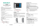
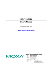
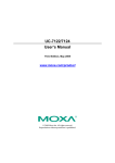
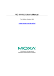
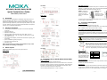
DIN-Rail Mounting UC-8430 The aluminum DIN-Rail attachment plate is included in the package. To attach the plate to the UC-8410/8416/8418/8430, situate the stiff metal spring towards the top. UC-8410/8416/8418/8430 STEP 1: Insert the top of the DIN-Rail into the slot just below the stiff metal spring. Quick Installation Guide Fifth Edition, March 2011 Rear View UC-8410 1. Overview To remove the UC-8410/8416/8418/8430 from the DIN-Rail, reverse Steps 1 and 2 above. The UC-8410/8416/8418/8430 embedded computers feature 8 RS-232/422/485 serial ports, 3 10/100 Mbps Ethernet ports, digital input and digital output channels, switch ports, CF and USB ports for storage expansion, and 2 VGA outputs (V8430 only). All of these features make the UC-8410/8416/8418/8430 computers ideal for your embedded applications. • • • • • • • • • 5. Connector Description Power Connector Connect the 12-48 VDC power line to the UC-8410/8416/8418/8430’s terminal block. The Ready LED will glow a steady green color when the OS is ready. UC-8416 2. Package Checklist 1 UC-8410 or UC-8416 or UC-8418 or UC-8430 embedded computer Wall-mounting kit DIN-Rail mounting kit Ethernet Cable: RJ45 to RJ45 cross-over cable, 100 cm CBL-4PINDB9F-100: 4-pin pin header to DB9 female console port cable, 100 cm Universal power adaptor (includes terminal block to power jack converter) Quick installation guide (this guide) Document and software CD Warranty card Grounding the UC-8410/8416/8418/8430 Grounding and wire routing help limit the effects of noise due to electromagnetic interference (EMI). Run the ground connection from the ground screw to the grounding surface prior to connecting the power. ATTENTION UC-8418 This product is intended to be mounted to a well-grounded mounting surface, such as a metal panel. SG: The Shielded Ground (sometimes called Protected Ground) contact is the right most contact of the 3-pin power terminal block connector when viewed from the angle shown here. Connect the SG wire to an appropriate grounded metal surface. Note: Please notify your sales representative if any of the above items are missing or damaged. 3. Panel Layout Refer to the following figures for the panel layouts. UC-8430 Front View Ethernet Port UC-8410 The 3 10/100 Mbps Ethernet ports (LAN 1, LAN 2, and LAN3), and 8 10/100 Mbps switch ports (UC-8416 only) use RJ45 connectors. 4. Installing the UC-8410/8416/8418/8430 UC-8416/8418 STEP 2: The DIN-Rail attachment unit will snap into place as shown below. Wall or Cabinet The two metal brackets included with the UC-8410/8416/8418/8430 can be used to attach it to a wall or the inside of a cabinet. Using two screws per bracket, first attach the brackets to the bottom of the UC-8410/8416/8418/8430. Next, use two screws per bracket to attach the UC-8410/8416/8418/8430 to a wall or cabinet. Pin 1 2 3 6 Signal ETx+ ETxERx+ ERx- VGA Connectors The MC-8430 comes with two D-Sub 15-pin female connectors to connect the VGA CRT monitors. Serial Port The 8 serial ports (P1 to P8) use RJ45 connectors. Each port can be configured by software as RS-232, RS-422, or RS-485. The pin assignments are shown in the following table (next page): P/N: 1802084000013 –1– –2– –3– Pin 1 2 3 4 5 6 7 8 RS-232 DSR RTS GND TXD RXD DCD CTS DTR RS-422/RS-485-4W – TXD+ GND TXDRXD+ RXD– – RS-485 – – GND – Data+ Data– – 6. Powering on the UC-8400 Computer To power on the UC-8410/8416/8418/8430, connect the “terminal block to power jack converter” to the UC-8410/8416/8418/8430’s DC terminal block (located on the left rear panel), and then connect the power adaptor. Note that the Shielded Ground wire should be connected to the right most pin of the terminal block. It takes approximately 30 seconds for the system to boot up. Once the system is ready, the Ready LED will light up. 7. Connecting the UC-8400 Computer to a PC CAN Ports (UC-8418 only) The UC-8418 has 2 CAN ports for connecting CAN devices. The CAN ports (CAN1 and CAN2) use DB9 male connectors. The pin assignments are shown in the following table: Pin 1 2 3 4 5 6 7 8 CAN – CAN-L – – – – CAN-H – There are two ways to connect the UC-8410/8416/8418/8430 to a PC: through the serial console port or by Telnet over the network. The COM settings for the serial console port are: Baudrate=115200 bps, Parity=None, Data bits=8, Stop bits =1, Flow Control=None. ATTENTION Remember to choose the “VT100” terminal type. Use the CBL-4PINDB9F-100 cable included with the product to connect a PC to the UC-8410/8416/8418/8430’s serial console port. DI, DO The UC-8410, UC-8416, and UC-8430 have 4 digital output channels and 4 digital input channels, and the UC-8418 has 12 digital input channels and 12 digital output channels. Refer to Hardware User's Manual for detailed pinouts and wiring. CompactFlash The UC-8410/8416/8418/8430 has one CompactFlash slot that supports CompactFlash type I/II card expansion. Currently, Moxa provides a CompactFlash card for storage expansion. Be sure to power off the computer before inserting or removing the CompactFlash card. The CompactFlash is mounted at /mnt/sda. Console Port The serial console port is a 4-pin pin-header RS-232 port that is located below the CF card socket. Use a screwdriver to remove the two screws holding the cover to the embedded computer’s housing. The port is used for the serial console terminal, which is useful for viewing boot-up messages. Use the CBL-4PINDB9F-100 cable included with the UC8410/8416/8418-LX to connect a PC to the UC-8410/8416/8418/8430’s serial console port. Reset Button Press and hold the “Reset” button continuously for at least 5 seconds to load the factory default configuration. After the factory default configuration has been loaded, the system will reboot automatically. The Ready LED will blink on and off for the first 5 seconds, and then maintain a steady glow once the system has rebooted. USB The UC-8410/8416/8418/8430 computers support 2 or 6 USB 2.0 hosts for external storage expansion. –4– To use Telnet you will need to know the UC-8410/8416/8418/ 8430’s IP address and netmask. The default LAN settings are shown below. For initial configuration, you may find it convenient to use a cross-over Ethernet cable to connect directly from the PC to the UC-8410/8416/8418/8430. LAN 1 LAN 2 LAN 3 Default IP Address 192.168.3.127 192.168.4.127 192.168.5.127 Netmask 255.255.255.0 255.255.255.0 255.255.255.0 Note that the LAN1 of the UC-8410/8416/8418/8430-CE and UC-8430-LX uses DHCP for both IP address and netmask. Once the UC-8410/8416/8418/8430 is powered on, the Ready LED will light up, and a login page will open. Use the following default Login name and Password to proceed. LAN 3= eth2 #vi /etc/network/interfaces //check the LAN interface first// After the boot setting of the LAN interface has been modified, use the following command to activate the LAN settings immediately: #sync; ifup –a Windows CE Models Use the netconfig utility to complete the task. Before using this utility, type netconfig -h to examine the usage of thecommand. \> netconfig –h netconfig usage: netconfig -n <AdapterName | Alias> [-EnableDHCP] [-i <IP address>] [-m <netmask>] [-g <gateway>] [-d <DNS server>] [-w <WINS Server>] [-noask] e.g.: netconfig -n IXP425ETHNPE1 -i 192.168.10.101 -g 192.168.10.254 : netconfig -n CS89501 -i 192.168.12.101 -m 255.255.0.0 : netconfig -n PCI\RTL81391 -EnableDHCP For example, if your development workstation has a LAN port at 192.168.1.x and the Domain Name Server (DNS) is at 192.168.2.6, then execute the following command. \> netconfig –n LAN1 –i 192.168.1.5 –m 255.255.255.0 –g 192.168.1.254 –d 192.168.2.6 Type netconfig to view the new settings. \> netconfig Ethernet Adapter [IXP4XXETHNPE1]: IP Address: 192.168.1.5 SubNet Mask: 255.255.255.0 Gateway: 192.168.1.254 DNS: 192.168.2.6 Ethernet Adapter [IXP4XXETHNPE2]: IP Address: 192.168.4.127 SubNet Mask: 255.255.255.0 Gateway: DNS: NOTE: Refer to the UC-8410/8416/8418/8430 User’s Manual for additional configuration information. Linux: Windows CE: Login: root Login: admin Password: root Password: admin For the UC-8430, you may connect the display with the display cable. After powering on the UC-8430, you will be able to access the computer for further configuration. 8. Configuring the Ethernet Interface www.moxa.com/support Linux Models If you use the console cable for first-time configuration of the network settings, use the following commands to edit the interfaces file: #ifdown –a //Disable LAN1/LAN2/LAN3 interface first, before you reconfigure the LAN settings. LAN 1 = eth0, LAN 2= eth1, –5– The Americas: Europe: Asia-Pacific: China: +1-714-528-6777 (toll-free: 1-888-669-2872) +49-89-3 70 03 99-0 +886-2-8919-1230 +86-21-5258-9955 (toll-free: 800-820-5036) 2010 Moxa Inc., All Rights Reserved –6–