1
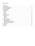
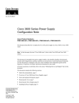
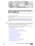
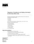
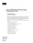
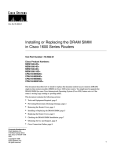
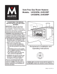
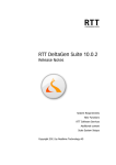
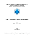
Doc. No. 78-4078-02
Upgrading Memory in Cisco 4000 Series Routers
Product Numbers:
MEM-4000-16D=
MEM-4000-4S=
MEM-4000-4F=
MEM-4000-8F=
MEM-4000-16F=
MEM-4000M-16D=
MEM-4000M-32D=
MEM-4000M-16S=
MEM-4000M-4F=
MEM-4500-32D=
MEM-4500-16S=
MEM-4500-4F=
MEM-4500M-16D=
MEM-4500M-32D=
MEM-4500M-8S=
MEM-4500M-16S=
MEM-4500M-4F=
MEM-4500M-16F=
MEM-4700-32D=
MEM-4700-8S=
MEM-4700-16S=
MEM-4700-8F=
MEM-4700-16F=
MEM-4700M-32D=
MEM-4700M-64D=
MEM-4700M-8S=
MEM-4700M-16S=
MEM-4700M-4F=
MEM-4700M-16F=
This document describes how to upgrade main, shared, Flash, and ROM memory in Cisco 4000
series routers. The Cisco 4000 series comprises the Cisco 4000, Cisco 4000-M, Cisco 4500,
Cisco 4500-M, Cisco 4700, and Cisco 4700-M routers.
Corporate Headquarters
Cisco Systems, Inc.
170 West Tasman Drive
San Jose, CA 95134-1706
USA
Copyright © 1997
Cisco Systems, Inc.
All rights reserved.
1
Note In this document, references to the Cisco 4000 series mean all routers in the series.
References to the Cisco 4000 router or to another individual router mean only that router.
Note When a procedure refers to the left side or right side of the chassis, component tray, or
motherboard, unless otherwise specified, it means as viewed from the front.
Use this document in conjunction with your router installation guide and the Cisco 4000 Series
Public Network Certification document. To see translated versions of the warnings in this document,
refer to the Cisco 4000 Series Installation Guide. If you have questions or need help, refer to the
sections “Cisco Documentation” and “Cisco Connection Online” later in this document.
This document contains the following sections:
•
•
•
•
•
•
•
•
•
•
•
•
•
•
•
•
•
•
Safety Recommendations, page 3
Memory Systems, page 5
Tools Required, page 7
Removing the Component Tray, page 8
The Cisco 4000 Flash EPROM Card, page 13
Removing Network Processor Modules, page 16
Memory Locations, page 18
SIMM Orientation, page 21
Upgrading Main Memory, page 22
Upgrading Shared Memory, page 25
Upgrading Flash Memory, page 26
Upgrading the ROM, page 28
Installing the Flash EPROM Card (Cisco 4000 Router Only), page 29
Replacing Network Processor Modules, page 30
Replacing the Component Tray, page 30
Replacing the Final Connections to the Router, page 30
Cisco Documentation, page 31
Cisco Connection Online, page 32
Warning Only trained and qualified personnel should be allowed to install or replace this
equipment.
Warning Before working on a chassis or working near power supplies, unplug the power cord on
AC units; disconnect the power at the circuit breaker on DC units.
2 Upgrading Memory in Cisco 4000 Series Routers
Safety Recommendations
Warning Before working on a system that has an ON/OFF switch, turn OFF the power and unplug
the power cord.
The following warning applies to routers with a DC power supply:
Warning Before performing any of the following procedures, ensure that power is removed from
the DC circuit. To ensure that all power is OFF, locate the circuit breaker on the panel board that
services the DC circuit, switch the circuit breaker to the OFF position, and tape the switch handle of
the circuit breaker in the OFF position.
Caution To avoid damaging electrostatic discharge (ESD)-sensitive components, ensure that you
have discharged all static electricity from your body before opening the chassis. Before performing
procedures described in this document, review the next section, “Safety Recommendations.”
Safety Recommendations
Follow these guidelines to ensure general safety:
•
•
•
•
Keep the chassis area clear and dust-free during and after installation.
•
•
Wear safety glasses when working under conditions that may be hazardous to your eyes.
Place the removed chassis cover in a safe place.
Keep tools away from walk areas where you or others could fall over them.
Do not wear loose clothing that may get caught in the chassis. Fasten your tie or scarf and roll up
your sleeves.
Do not perform any action that creates a potential hazard to people or makes the equipment
unsafe.
Warning The ISDN connection is regarded as a source of voltage that should be inaccessible to
user contact. Do not attempt to tamper with or open any public telephone operator (PTO)-provided
equipment or connection hardware. Any hardwired connection (other than by a nonremovable,
connect-one-time-only plug) must be made only by PTO staff or suitably trained engineers.
Warning The Ethernet 10BaseT, Token Ring, serial, console, and auxiliary ports contain safety
extra-low voltage (SELV) circuits. BRI circuits are treated like telephone-network voltage (TNV)
circuits. Avoid connecting SELV circuits to TNV circuits.
Upgrading Memory in Cisco 4000 Series Routers
3
Safety Recommendations
Safety with Electricity
Warning Before working on equipment that is connected to power lines, remove jewelry (including
rings, necklaces, and watches). Metal objects will heat up when connected to power and ground and
can cause serious burns or weld the metal object to the terminals.
Follow these guidelines when working on equipment powered by electricity:
•
Locate the room’s emergency power-OFF switch. Then, if an electrical accident occurs, you can
quickly shut the power OFF.
•
•
Before working on the system, turn OFF the power and unplug the power cord.
Disconnect all power before doing the following:
— Working on or near power supplies
— Installing or removing a router chassis or network processor module
— Performing a hardware upgrade
•
•
Do not work alone if potentially hazardous conditions exist.
•
•
Never assume that power is disconnected from a circuit. Always check.
Look carefully for possible hazards in your work area, such as moist floors, ungrounded power
extension cables, and missing safety grounds.
If an electrical accident occurs, proceed as follows:
— Use caution, and do not become a victim yourself.
— Turn OFF power to the system.
— If possible, send another person to get medical aid. Otherwise, determine the condition of the
victim and then call for help.
— Determine if the person needs rescue breathing or external cardiac compressions; then take
appropriate action.
Preventing Electrostatic Discharge Damage
Electrostatic discharge (ESD) can damage equipment and impair electrical circuitry. It occurs when
electronic printed circuit cards are improperly handled and can result in complete or intermittent
failures. Always follow ESD prevention procedures when removing and replacing cards. Ensure that
the router chassis is electrically connected to earth ground. Wear an ESD-preventive wrist strap,
ensuring that it makes good skin contact. Connect the clip to an unpainted surface of the chassis
frame to safely channel unwanted ESD voltages to ground. To properly guard against ESD damage
and shocks, the wrist strap and cord must operate effectively. If no wrist strap is available, ground
yourself by touching the metal part of the chassis.
Caution For safety, periodically check the resistance value of the antistatic strap, which should be
between 1 and 10 megohms (Mohm).
4 Upgrading Memory in Cisco 4000 Series Routers
Memory Systems
Memory Systems
Cisco 4000 series routers contain the following memory systems:
•
Main memory consists of dynamic random-access memory (DRAM) single in-line memory
modules (SIMMs). It is reserved for the CPU to execute Cisco Internetwork Operating System
(Cisco IOS) software and to hold the running configuration and routing tables.
•
Shared memory also consists of DRAM SIMMs, and buffers data transmitted or received by the
router’s network interfaces.
•
Flash memory stores the Cisco IOS software image. Flash memory is provided as erasable
programmable read-only memory (EPROM) on the original Cisco 4000 daughter card and as
Flash SIMMs on the replacement Cisco 4000 daughter card and in all other Cisco 4000 series
routers. In the Cisco 4500, Cisco 4500-M, Cisco 4700, and Cisco 4700-M routers, Flash
memory also stores the boot helper, a subset of Cisco IOS software that allows the router to boot
when Flash memory does not contain a valid Cisco IOS image.
Because Flash memory holds the Cisco IOS image, upgrading it causes the image to be lost. To
restore it, you need a Trivial File Transfer Protocol (TFTP) file server that holds the desired
image. You can then download the Cisco IOS files into the upgraded Flash memory using TFTP.
Consult your network administrator about the availability of TFTP file servers and Cisco IOS
software on your network. Refer to the Cisco IOS configuration guides and command references
for TFTP procedures. For information about Cisco publications, refer to the section “Cisco
Documentation” later in this document.
Note One upgraded router can serve as a TFTP server to upgrade other routers.
•
EPROM stores the ROM monitor and the boot helper in the Cisco 4000 and the Cisco 4000-M.
In the Cisco 4500, Cisco 4500-M, Cisco 4700, and Cisco 4700-M routers, EPROM stores only
the ROM monitor; the boot helper is stored in Flash memory.
•
Nonvolatile random-access memory (NVRAM) stores the configuration file and virtual
configuration register. This memory cannot be upgraded.
Figure 1 shows a block diagram of EPROM-based and Flash-based memory systems in Cisco 4000
series routers.
Upgrading Memory in Cisco 4000 Series Routers
5
Memory Systems
Figure 1
Cisco 4000 Series EPROM-Based and Flash-Based Memory Systems
Cisco 4000 and Cisco 4000-M
EPROM-based
Boot helper
(xboot)
Flash-memory based
Cisco IOS
ROM monitor
Cisco 4500, Cisco 4500-M, Cisco 4700, and Cisco 4700-M
ROM monitor
Flash-memory based
Boot helper
(xboot)
Cisco IOS
H3537
EPROM-based
The following sections describe memory systems in each router in the Cisco 4000 series.
Cisco 4000
The Cisco 4000 router contains the following memory systems:
•
•
•
Four SIMM sockets for main memory (4 x 1 MB or 4 x 4 MB).
Four SIMM sockets for shared memory (4 x 1 MB).
One socket for a memory daughter card containing either Flash EPROM or Flash SIMMs. The
original daughter cards support either 2 or 4 MB of EPROM. Replacement daughter cards
support 8 or 16 MB of Flash SIMMs, using either two 4-MB SIMMs or two 8-MB SIMMs.
Cisco 4000-M
The Cisco 4000-M router contains the following memory systems:
•
•
•
One SIMM socket for main memory (8, 16, or 32 MB).
One SIMM socket for shared memory (4 or 16 MB).
Two SIMM sockets for Flash memory. One or both may be filled. When both are filled, equal
memory sizes are required (4 MB, or 4 and 4 MB).
Cisco 4500
The Cisco 4500 router contains the following memory systems:
•
Two SIMM sockets for main memory. Both must be filled, and they must contain equal memory
sizes (4 and 4 MB, or 16 and 16 MB).
•
•
One SIMM socket for shared memory (4 or 16 MB).
Two SIMM sockets for system Flash memory, plus one for boot helper Flash memory. One or
both system Flash-memory sockets may be filled. When both are filled, equal memory sizes are
required (4 MB, or 4 and 4 MB).
6 Upgrading Memory in Cisco 4000 Series Routers
Tools Required
Cisco 4500-M
The Cisco 4500-M router contains the following memory systems:
•
Two SIMM sockets for main memory. Both must be filled, and they must contain equal memory
sizes (4 and 4 MB, 8 and 8 MB, or 16 and 16 MB).
•
•
One SIMM socket for shared memory (4 or 16 MB).
Two SIMM sockets for system Flash memory, plus one for boot helper Flash memory. One or
both system Flash-memory sockets may be filled. When both are filled, equal memory sizes are
required (4 MB, 8 MB, 4 and 4 MB, or 8 and 8 MB).
Cisco 4700
The Cisco 4700 router contains the following memory systems:
•
Two SIMM sockets for main memory. Both must be filled, and they must contain equal memory
sizes (4 and 4 MB, or 16 and 16 MB).
•
•
One SIMM socket for shared memory (4, 8, or 16 MB).
Two SIMM sockets for system Flash memory, plus one for boot helper Flash memory. One or
both system Flash-memory sockets may be filled. When both are filled, equal memory sizes are
required (4 MB, 8 MB, 4 and 4 MB, or 8 and 8 MB).
Cisco 4700-M
The Cisco 4700-M router contains the following memory systems:
•
Two SIMM sockets for main memory. Both must be filled, and they must contain equal memory
sizes (4 and 4 MB, 16 and 16 MB, or 32 and 32 MB).
•
•
One SIMM socket for shared memory (4, 8, or 16 MB).
Two SIMM sockets for system Flash memory, plus one for boot helper Flash memory. One or
both system Flash-memory sockets may be filled. When both are filled, equal memory sizes are
required (4 MB, 8 MB, 4 and 4 MB, or 8 and 8 MB).
Tools Required
You need the following tools to remove and upgrade main, shared, Flash, and ROM memory:
•
•
•
•
•
ESD-preventive wrist strap
Antistatic bag (for removed components)
ESD mat (for removed network processor modules)
Number 1 Phillips screwdriver (to loosen the chassis release screw)
Number 2 Phillips screwdriver (to remove network processor modules)
To upgrade ROM or to add Flash EPROM to a Cisco 4000 router Flash EPROM card, you also need:
•
•
An IC extraction tool or small flat-blade screwdriver
Needlenose pliers (to straighten bent pins)
Upgrading Memory in Cisco 4000 Series Routers
7
Removing the Component Tray
Removing the Component Tray
To gain access to the router’s memory, you must first remove the component tray from the chassis.
Warning Before working on a chassis or working near power supplies, unplug the power cord on
AC units; disconnect the power at the circuit breaker on DC units.
Warning Do not touch the power supply when the power cord is connected. For systems with a
power switch, line voltages are present within the power supply even when the power switch is OFF
and the power cord is connected. For systems without a power switch, line voltages are present
within the power supply when the power cord is connected.
The following warning applies to routers with DC power supplies:
Warning Before performing any of the following procedures, ensure that power is removed from
the DC circuit. To ensure that all power is OFF, locate the circuit breaker on the panel board that
services the DC circuit, switch the circuit breaker to the OFF position, and tape the switch handle of
the circuit breaker in the OFF position.
Some Cisco 4000 series routers have a safety latch tab on the chassis (see Figure 2) and others do
not (see Figure 3).
Figure 2
Chassis with a Safety Latch
Chassis shell
Safety latch tab
AUX
CONSOLE
INPUT 100-240VAC
Rear of chassis
8 Upgrading Memory in Cisco 4000 Series Routers
Hand supporting
component tray
50/60HZ 3.0-1.5 AMPS
Handle
H1965
Chassis release
screw
Removing the Component Tray
Figure 3
Chassis without a Safety Latch
Chassis shell
AUX
CONSOLE
INPUT 100-240VAC
Rear of chassis
Support the component
tray with your hand
50/60HZ 3.0-1.5 AMPS
H2899
Chassis release
screw
Handle
Follow these steps to remove the component tray from a chassis:
Step 1
Turn OFF the power.
Step 2
Attach your ESD-preventive wrist strap.
Step 3
Remove all network and power cables.
Warning Before opening the chassis, disconnect the telephone-network cables to avoid contact
with telephone-network voltages.
Warning Do not work on the system or connect or disconnect cables during periods of lightning
activity.
Step 4
If you have a DC-powered router, follow these steps to remove the power cables:
•
•
•
Step 5
Use a screwdriver to loosen the captive installation screws on the terminal block cover.
Lift and remove the terminal block cover.
Use a screwdriver to remove the three power leads from the terminal block in the
following order: negative, positive, then ground.
Using a Number 2 Phillips screwdriver, loosen the nonremovable chassis release screw
on the rear panel of the chassis.
Caution When you remove the component tray from the chassis, support it from underneath, either
on your work surface or with your hands.
Upgrading Memory in Cisco 4000 Series Routers
9
Removing the Component Tray
Step 6
To remove the component tray, pull on the handle at the upper right corner of the rear
panel.
If your chassis has a safety latch (see Figure 2), slide the component tray out of the
chassis shell just until the safety latch catches. Support the component tray with one hand,
push down on the safety latch tab, and pull the component tray out the rest of the way.
If your chassis does not have a safety latch (see Figure 3), support the component tray
with one hand while you slide it out of the chassis shell.
Step 7
Set the tray on your work surface.
Figure 4, Figure 5, Figure 6, and Figure 7 show component trays for routers in the Cisco 4000 series.
(Figure 4 shows the original Flash EPROM daughter card for the Cisco 4000; if your daughter card
has been replaced, its appearance will differ.)
Figure 4
Cisco 4000 Component Tray
Token Ring module
Ethernet module
EPROM card
mounting screw
Module
mounting
screws
Module handle
LED
Front
Module handle
INHIBITED
FW1
FW2
Module cutaway view
128-pin module connector
Module mounting
screw
Dual serial module
10 Upgrading Memory in Cisco 4000 Series Routers
Boot ROMs
EPROM card
mounting
screw
EPROM card
cutaway view
96-pin EPROM
connector
H1047a
Module handle
ALLOWED
Software update
LEDs
Removing the Component Tray
Cisco 4000-M Component Tray
Module
mounting
screw
Module handle
LED
J1
Module
mounting
screw
Module handle
Front
of the
chassis
LEDs
Module handle
FW1
FW2
128-pin connector
(cutaway view)
Module mounting
screw
H2404
Figure 5
Boot ROMs
Upgrading Memory in Cisco 4000 Series Routers
11
Removing the Component Tray
Figure 6
Cisco 4500, Cisco 4700, and Older Cisco 4500-M Component Tray
Token Ring module
Ethernet module
Module
mounting
screws
Module handle
LED
Front of chassis
Module handle
LEDs
U61
U63
U64
J6
Module handle
H2690
U68
Module cutaway view
128-pin module connector
Dual serial module
12 Upgrading Memory in Cisco 4000 Series Routers
Module mounting
screw
ROM monitor
The Cisco 4000 Flash EPROM Card
Figure 7
Cisco 4700-M and Newer Cisco 4500-M Component Tray
Token Ring module
Ethernet module
Module
mounting
screws
Module handle
LED
J1
Front of the chassis
Module handle
LEDs
U61
U63
U64
J6
Module handle
H6669
U78
Module cutaway view
128-pin module connector
Dual serial module
Module mounting
screw
ROM monitor
The Cisco 4000 Flash EPROM Card
In the Cisco 4000 router only, Flash memory resides on a separate daughter card. In all other routers
in the Cisco 4000 series, Flash memory resides on the motherboard.
If you are upgrading Flash memory in a Cisco 4000 router to 8 or 16 MB by replacing the original
Flash EPROM card, or if you are upgrading main memory in a Cisco 4000 router, you must remove
the Flash EPROM card. Continue with the next section, “Removing the Flash EPROM Card.”
If you are upgrading Flash memory in a Cisco 4000 router from 2 to 4 MB by adding EPROMs to
the original daughter card, you do not need to remove the Flash EPROM card. Continue with the
section “Adding Memory to the Flash EPROM Card” later in this document.
If you are upgrading only shared memory in a Cisco 4000 router, you do not need to remove the
Flash EPROM card. Continue with the section “Removing Network Processor Modules” later in this
document.
If you are upgrading memory in any other router in the Cisco 4000 series, there is no Flash EPROM
card. Continue with the section “Removing Network Processor Modules” later in this document.
Upgrading Memory in Cisco 4000 Series Routers
13
The Cisco 4000 Flash EPROM Card
Removing the Flash EPROM Card
Follow these steps to remove the Flash EPROM card from a Cisco 4000 router in order to gain access
to main memory, or to replace the original Flash EPROM card:
Step 1
Using a Number 1 Phillips screwdriver, remove the two mounting screws from the top of
the card and set them aside. See Figure 4 for the location of these screws. This figure
shows the original Flash EPROM daughter card for the Cisco 4000; if your daughter card
has been replaced, its appearance will differ.
Caution To prevent damage to the Flash EPROM card, handle it only by the sides.
Step 2
Figure 8
Holding the Flash EPROM card by its edges, pull straight up to lift it out of its 96-pin
connector. (See Figure 8.)
Cisco 4000 Flash EPROM Card and Connector, Side View
96-pin connector
If you are also upgrading shared memory on the Cisco 4000 motherboard, continue with the section
“Removing Network Processor Modules” later in this document.
If you are upgrading only main memory on the Cisco 4000 motherboard, continue with the section
“Memory Locations” later in this document.
If you are installing a new Flash EPROM card, you may also need to install updated boot ROMs to
provide support for the new card. If your boot ROMs are Cisco IOS Release 10.2(8) or earlier,
continue with the section “Upgrading the ROM” later in this document. If your ROM supports a later
version of the Cisco IOS, you do not need to replace the boot ROMs. Continue with the section
“Installing the Flash EPROM Card (Cisco 4000 Router Only)” later in this document.
Adding Memory to the Flash EPROM Card
Follow the procedures in this section to install additional Flash EPROMs on the original Cisco 4000
Flash EPROM card, shown in Figure 4 and Figure 9. You must also replace the existing
programmable array logic (PAL) device with a new PAL.
Note You do not need to remove the Flash EPROM card for this upgrade procedure. Do not try to
remove the existing Flash EPROMs; they are permanently installed.
14 Upgrading Memory in Cisco 4000 Series Routers
H4466
Software update jumpers
The Cisco 4000 Flash EPROM Card
Caution Correct placement of the Flash EPROMs and PAL is crucial. If improperly positioned, the
new components could be damaged when you power ON the router.
Installing Flash-Memory EPROMs
To install new Flash EPROMs in the eight open sockets (U141 to U148) on the Flash EPROM card
(see Figure 9), align the notch in each EPROM with the notch in an EPROM socket. Insert the Flash
EPROM into the sockets, being careful not to bend any pins. To straighten a bent pin, use needlenose
pliers.
All Flash EPROM sockets should be filled.
Figure 9
Original Cisco 4000 Flash EPROM Card
Software update jumper
Software
ALLOWED
update
W1
INHIBITED
DC/DC
converter
U41
U42
U43
U44
U141
U142
U143
U144
U45
U46
U47
U48
U145
U146
U147
U148
U2
H1049a
PAL
Card-mounting
screw location
Card-mounting
screw location
Replacing the Flash EPROM Card PAL
Follow these steps to replace the PAL at location U2 in Figure 9:
Step 1 Using an IC extraction tool or small flat-blade screwdriver, gently lift the existing PAL out
of its socket, being careful not to damage the underlying printed circuit card.
Step 2 Align the notch in the replacement PAL with the notch in the PAL socket. Insert the PAL
into the socket, being careful not to bend any pins. To straighten a bent pin, use needlenose
pliers.
Flash Jumper Settings
To enable or disable writing a new version of the Cisco IOS to Flash EPROM, set the jumper shown
at the upper left of Figure 9. To allow software update (the factory-set default), place the jumper on
the left two pins. To prevent software update, place the jumper on the right two pins.
To replace the component tray in the chassis shell, continue with the section “Replacing the
Component Tray” later in this document.
Upgrading Memory in Cisco 4000 Series Routers
15
Removing Network Processor Modules
Removing Network Processor Modules
To gain access to shared memory in all routers, you must remove the center network processor
module from the component tray. In the Cisco 4000 router, you must also remove the module on the
right (as viewed from the front of the router). To access the ROM monitor in Cisco 4500,
Cisco 4500-M, Cisco 4700, and Cisco 4700-M routers, remove the module on the left.
If you are upgrading only main memory or Flash memory in a Cisco 4000-M, Cisco 4500,
Cisco 4500-M, Cisco 4700, or Cisco 4700-M router, or the ROM monitor in a Cisco 4000-M router,
you do not need to remove network processor modules. Continue with the section “Memory
Locations” later in this document.
If you are upgrading main memory or Flash memory in a Cisco 4000 router, refer to the section “The
Cisco 4000 Flash EPROM Card” earlier in this document.
Caution Some network processor modules are fastened to the rear of the chassis with two external
screws. You must remove these screws before you can lift the module out of the chassis.
Follow these steps to remove a module:
Step 1
Using a Number 1 Phillips screwdriver, remove the internal module mounting screw from
the end of the module card. Remove the two external rear mounting screws, if present,
from the rear panel and set them aside.
Step 2
Hold the module handle and pull it straight up to lift the module out of its connector. (See
Figure 10.)
Step 3
Place the removed module on an ESD mat.
Caution Do not wiggle the module’s handle or exert any side-to-side pressure. The handle may
work loose and damage the module.
Caution If any of the modules have daughter cards projecting at right angles to the module (see
Figure 11), do not bend the module during installation, because the daughter cards could become
disconnected. Carefully reseat any loosened cards, handling them by the edges without touching any
components.
16 Upgrading Memory in Cisco 4000 Series Routers
Removing Network Processor Modules
Figure 10
Removing Network Processor Modules
Module handles
Male module
connector
(cutaway view)
Female module
connector on the
motherboard
Safety latch
H1048a
Chassis
wall
Module mounting
screw
Figure 11
Network Processor Module Daughter Card Connections
Daughter
card
Correct installation showing
connectors firmly seated.
H2168
Daughter
card
Incorrect installation showing
connectors not firmly seated.
Upgrading Memory in Cisco 4000 Series Routers
17
Memory Locations
Memory Locations
Figure 12, Figure 13, Figure 14, and Figure 15 show locations of memory components on
Cisco 4000 series router motherboards.
Figure 12
Cisco 4000 Memory Locations
Shared-memory
SIMM sockets
(4 places)
Motherboard
Main memory SIMM sockets
with proper SIMM orientation
(4 places)
H2460
Chassis Front
18 Upgrading Memory in Cisco 4000 Series Routers
Memory Locations
Cisco 4000-M Memory Locations
Shared-memory
SIMM socket
Main memory SIMM socket
with proper SIMM orientation
Motherboard
Chassis Front
U3
J1
U44
J7 J8
Pin 1
J4
J6
Flash memory
SIMM sockets
U114
U110
FW1
J7
FW2
Pin 1
J6
J8
H2403
Figure 13
Boot ROM jumpers (J7 and J8)
Boot ROMs
J6 write-enable
jumper position
Upgrading Memory in Cisco 4000 Series Routers
19
Memory Locations
Figure 14
Cisco 4500, Cisco 4700, and Older Cisco 4500-M Memory Locations
Main memory SIMM
sockets with correct
SIMM orientation
Shared-memory
SIMM and socket
Motherboard
Front of chassis
System Flash memory 1
System Flash memory 0
RxBoot Flash memory
J6
J1
H2449
NVRAM
Jumped pins
1 and 2
U68
Jumper in place enables
writing to Flash memory
ROM monitor
20 Upgrading Memory in Cisco 4000 Series Routers
SIMM Orientation
Figure 15
Cisco 4700-M and Newer Cisco 4500-M Memory Locations
Motherboard
Shared-memory
SIMM and socket
Main memory SIMM sockets
with correct SIMM orientation
J1
Jump pins 1 and 2
Front of chassis
System Flash memory 1
System Flash memory 0
RxBoot Flash memory
NVRAM
H6665
J6
J5
U78
Jump pins
1 and 2
ROM monitor
Jumper in place enables
writing to Flash memory
SIMM Orientation
SIMMs are manufactured with a polarization notch to ensure proper orientation, and alignment holes
that fit over guide posts to ensure proper positioning.
Figure 16 shows the polarization notch and alignment holes on a typical SIMM. SIMMs vary in their
physical dimensions and in the number, size, and location of components on the surface of the card,
depending on the router they are installed in, the type of memory, and the SIMM manufacturer.
Figure 16
Typical Cisco 4000 Series SIMM
H1154a
Alignment holes
Polarization notch
Connector edge
Caution To avoid damaging ESD-sensitive components, observe all ESD precautions when
handling SIMMs. To avoid damaging the motherboard or the SIMM, avoid excessive force when you
remove or replace SIMMs.
Upgrading Memory in Cisco 4000 Series Routers
21
Upgrading Main Memory
Upgrading Main Memory
A main-memory upgrade entails removing the existing main-memory SIMMs and replacing them
with the upgraded SIMMs. If you are upgrading a Cisco 4000 router, you must first remove the Flash
EPROM card. See the section “Removing the Flash EPROM Card” earlier in this document.
Removing Main-Memory SIMMs
Follow these steps to remove main-memory SIMMs:
Step 1
Find the main-memory SIMM sockets on the router’s motherboard, as shown at the upper
right of Figure 12, Figure 13, Figure 14, or Figure 15. These sockets hold the SIMMs
vertically.
Caution Handle SIMMs by the card edges only. SIMMs are ESD-sensitive components and can be
damaged by mishandling.
Step 2
Remove one SIMM at a time, beginning with the SIMM closest to the edge of the
motherboard in the Cisco 4000, and the SIMM farthest from the edge of the motherboard
in all other routers.
Step 3
To lift the SIMM out of its socket, pull the spring clips on both sides outward and tilt the
SIMM free of the clips, toward the right side in the Cisco 4000, as viewed from the front
of the router (see Figure 17), and toward the left side in all other routers (see Figure 18).
Step 4
Hold the SIMM by the edges with your thumb and index finger and lift it out of the socket.
Place the removed SIMM in an antistatic bag to protect it from ESD damage.
Step 5
Repeat Step 2 through Step 4 for any remaining main-memory SIMMs.
Figure 17
Removing Main Memory SIMMs (Cisco 4000)
Top view
Front of chassis
SIMM
polarization
notch
22 Upgrading Memory in Cisco 4000 Series Routers
1. Pull the locking
spring clips outward.
H9406
2. Push the top of the
SIMM forward.
Upgrading Main Memory
Figure 18
Removing Main Memory SIMMs (All Other Routers)
Top view
Front of chassis
2. Push the top of the
SIMM forward.
H9408
1. Pull the locking
spring clips outward.
SIMM
polarization
notch
Installing Main-Memory SIMMs
Follow these steps to install main-memory SIMMs:
Step 1
Find the main-memory SIMM sockets on the router’s motherboard, as shown in
Figure 12, Figure 13, Figure 14, or Figure 15. All sockets should be empty. If they are
not, follow the steps in the previous section, “Removing Main-Memory SIMMs.”
Caution Handle SIMMs by the card edges only. SIMMs are ESD-sensitive components and can be
damaged by mishandling.
Step 2
Hold the SIMM with the connector edge at the bottom and the polarization notch toward
the rear of the router.
Step 3
Beginning with the socket farthest from the edge of the motherboard in the Cisco 4000,
and the socket nearest the edge of the motherboard in all other routers, insert the SIMM
at an angle, tilted toward the right side in the Cisco 4000, as viewed from the front of the
router (see Figure 19), and toward the left side in all other routers (see Figure 20). Rock
it into a vertical position, using the minimum amount of force required. When the SIMM
is properly seated, the socket guide posts fit through the alignment holes, and the spring
clips click into place.
Step 4
Ensure that the SIMM is straight and that the alignment holes line up with the plastic
guides on the socket. It is normal to feel some resistance, but do not use excessive force
on the SIMM, and do not touch the surface components.
Step 5
Repeat Step 2 through Step 4 for each main-memory SIMM.
If you are finished upgrading memory, continue with the section “Installing the Flash EPROM Card
(Cisco 4000 Router Only)” later in this document for a Cisco 4000 router, or the section “Replacing
the Component Tray” for any other model.
Upgrading Memory in Cisco 4000 Series Routers
23
Upgrading Main Memory
Figure 19
Installing Main-Memory SIMMs (Cisco 4000)
View from front of chassis
1. Insert the SIMM into the socket
at an angle from vertical.
2. Push the top of the SIMM
down and back.
3. The socket guide posts fit through
the holes in the SIMM.
H9410
4. The locking springs clip the back
of the SIMM.
Figure 20
Installing Main-Memory SIMMs (All Other Routers)
View from front of chassis
1. Insert the SIMM into the socket
at an angle from vertical.
2. Push the top of the SIMM
down and back.
H9411
3. The socket guide posts fit through
the holes in the SIMM.
4. The locking springs clip the back
of the SIMM.
24 Upgrading Memory in Cisco 4000 Series Routers
Upgrading Shared Memory
Upgrading Shared Memory
A shared-memory upgrade entails removing the existing shared-memory SIMMs and replacing
them with the upgraded SIMMs. You must first remove the network processor modules from the
component tray. See the section “Removing Network Processor Modules” earlier in this document.
Removing Shared-Memory SIMMs
Follow these steps to remove shared-memory SIMMs:
Step 1
Find the shared-memory SIMM sockets on the motherboard, as shown at the left of
Figure 12, Figure 13, Figure 14, or Figure 15. These sockets hold the SIMMs
horizontally.
Caution Handle SIMMs by the card edges only. SIMMs are ESD-sensitive components and can be
damaged by mishandling.
Step 2
The SIMMs are held in place at each end by spring clips. To remove a SIMM, pull the
clips outward. Holding the SIMM by the edges with your thumb and index finger, angle
it upward, and pull it out.
Step 3
Place the removed SIMM in an antistatic bag to protect it from ESD damage.
Step 4
Repeat Step 2 and Step 3 for any remaining shared-memory SIMMs.
Installing Shared-Memory SIMMs
Follow these steps to install shared-memory SIMMs:
Step 1
Find the shared-memory SIMM sockets on the motherboard, as shown in Figure 12,
Figure 13, Figure 14, or Figure 15. All sockets should be empty. If they are not, follow
the steps in the previous section, “Removing Shared-Memory SIMMs.”
Caution Handle SIMMs by the card edges only. SIMMs are ESD-sensitive components and can be
damaged by mishandling.
Step 2
Hold the SIMM with the polarization notch toward the rear of the router and the
connector edge toward the left side of the router (as viewed from the front).
Step 3
To insert a SIMM, angle it into position (see Figure 21), then carefully push down and
back on the edges, holding each edge so that it snaps securely into place. The two spring
clips should fit over the edge of the SIMM and hold it horizontally.
Step 4
Ensure that the SIMM is straight and that the alignment holes line up with the plastic
guides on the socket. It is normal to feel some resistance, but do not use excessive force
on the SIMM, and do not touch the surface components.
Step 5
Repeat Step 2 through Step 4 for any remaining shared-memory SIMMs.
Upgrading Memory in Cisco 4000 Series Routers
25
Upgrading Flash Memory
Figure 21
Installing Shared-Memory SIMMs
Top view
Push the SIMM down and back
Polarization notch
Side view, SIMM inserted
Push the SIMM down and back
H1052a
The socket guide posts
insert through the SIMM holes
(on both sides)
If you are finished upgrading memory, continue with the section “Replacing Network Processor
Modules” later in this document.
Upgrading Flash Memory
Flash memory in the Cisco 4000 router resides on a separate daughter card. To add memory to the
original daughter card, see the section “Adding Memory to the Flash EPROM Card” earlier in this
document. To replace the card, see the sections “Removing the Flash EPROM Card” and “Installing
the Flash EPROM Card (Cisco 4000 Router Only).” When you upgrade the Flash EPROM card, you
also install new boot ROMs (which are included in the upgrade kit) and change the boot ROM
jumpers (J5 and J6).
To upgrade system Flash memory in other routers, add a second Flash SIMM. For the Cisco 4500-M,
Cisco 4700, and Cisco 4700-M routers, you can also replace 4-MB Flash-memory SIMMs with
8-MB SIMMs. In all routers, when both system Flash-memory sockets are filled, equal memory
sizes are required.
26 Upgrading Memory in Cisco 4000 Series Routers
Upgrading Flash Memory
Removing Flash-Memory SIMMs
To remove a Flash-memory SIMM, follow these steps:
Step 1
Find the system Flash-memory sockets on the motherboard, as shown at the lower right
of Figure 13, Figure 14 or Figure 15. These sockets hold the SIMMs vertically.
Caution Handle SIMMs by the edges only. SIMMs are ESD-sensitive components and can be
damaged by mishandling.
Step 2
Remove any SIMMs that you want to replace, beginning with system Flash memory
socket 1, as shown in Figure 13, Figure 14, or Figure 15. Pull the spring clips on both
sides outward and tilt the SIMM free of the clips, toward the right side of the router, as
viewed from the front. (See Figure 22.)
Step 3
Hold the SIMM by the edges with your thumb and index finger and lift it out of the socket.
Place the removed SIMM in an antistatic bag to protect it from ESD damage.
Step 4
If necessary, repeat Step 2 and Step 3 for the SIMM in system Flash memory socket 0.
Figure 22
Removing Flash-Memory SIMMs
Top view
Front of chassis
SIMM polarization notch
1. Pull the locking
spring clips outward.
H9407
2. Push the top of the
SIMM forward.
Installing Flash-Memory SIMMs
To install a Flash-memory SIMM, follow these steps:
Step 1
Find the system Flash-memory sockets on the motherboard, as shown in Figure 13,
Figure 14, or Figure 15.
Caution Handle SIMMs by the edges only. SIMMs are ESD-sensitive components and can be
damaged by mishandling.
Step 2
Hold the SIMM with the connector edge at the bottom and the polarization notch toward
the rear of the router. (See Figure 23.)
Upgrading Memory in Cisco 4000 Series Routers
27
Upgrading the ROM
Step 3
Begin with system Flash memory socket 0, as shown in Figure 13, Figure 14, or
Figure 15. Insert the SIMM at an angle, tilted toward the right side of the router (as
viewed from the front). Rock it into a vertical position (see Figure 23), using the
minimum amount of force required. When the SIMM is properly seated, the socket guide
posts fit through the alignment holes, and the connector springs click into place.
Step 4
Ensure that the SIMM is straight and that the alignment holes line up with the plastic
guides on the socket. It is normal to feel some resistance, but do not use excessive force
on the SIMM, and do not touch the surface components.
Step 5
If socket 0 is already filled, or to install a second Flash-memory SIMM, repeat Step 2
through Step 4 for system Flash memory socket 1.
If you are finished upgrading memory, continue with the section “Replacing the Component Tray”
later in this document.
Figure 23
Installing Flash-Memory SIMMs
View from front of chassis
1. Insert the SIMM into the socket
at an angle from vertical.
2. Push the top of the SIMM
down and back.
3. The socket guide posts fit through
the holes in the SIMM.
H9409
4. The locking springs clip the back
of the SIMM.
Upgrading the ROM
To upgrade the ROM monitor on a Cisco 4500, Cisco 4500-M, Cisco 4700, or Cisco 4700-M router,
you must first remove the network processor modules. See the section “Removing Network
Processor Modules” earlier in this document. You can upgrade the boot ROMs on the Cisco 4000
and Cisco 4000-M without removing network processor modules.
To upgrade a ROM device, remove the old one and replace it with the new one.
Caution Correct placement of the ROM is crucial. If improperly positioned, the new ROM could
be damaged when you power ON the router.
Follow these steps to replace the ROM:
Step 1
Locate the ROM or ROMs on the motherboard, as shown in Figure 12, Figure 13,
Figure 14, or Figure 15.
Step 2
Gently remove the old ROM with an IC extraction tool or a small flat-blade screwdriver,
and set it aside.
28 Upgrading Memory in Cisco 4000 Series Routers
Installing the Flash EPROM Card (Cisco 4000 Router Only)
Align the notch in the new ROM with the notch in the socket, ignoring the orientation of
the label. Insert the ROM in its socket, being careful not to bend any pins. To straighten
a bent pin, use needlenose pliers.
Step 3
Caution The notch on the ROM must match the notch on the socket. Installing the ROM backward
will damage it.
For Cisco 4000 routers only, set jumpers J5 and J6 to designate the capacity of the Boot
ROMs. For boot ROMs version Cisco IOS Release10.2(8) and higher short pins 2 and 3
on both jumper locations, J5 and J6 as shown in the 8 MB boot ROMs position. To short
pins 2 and 3 on J5 and J6, install the jumper block over the two pins located away from
the Flash EPROM card, as shown in the 8 MB boot ROMs position on Figure 24. For 4
MB boot ROMs, which are prior to version 10.2(8), install the jumper on the upper two
pins at J6 and the lower two pins at J5.
Cisco 4000 Boot ROMs
SOFTWARE UPDATE
ALLOWED
W1
Figure 24
INHIBITED
Step 4
LED
FW1
J5 J6
J5 J6
Boot ROMs
8 MB boot ROMs
4 MB boot ROMs
H4465
FW2
Installing the Flash EPROM Card (Cisco 4000 Router Only)
If you removed the Flash EPROM card from a Cisco 4000 router to gain access to main memory, or
to replace the card with an upgraded one, follow these steps to install the old or replacement card:
Step 1
Line up the card with the 96-pin socket and screw holes. (See Figure 8.)
Step 2
Holding the card horizontally by its edges, insert it into the socket by pushing straight
down, being careful not to bend the pins.
Step 3
Using a Number 1 Phillips screwdriver, reinstall the two card-mounting screws.
Caution Do not overtorque the screw. The card or the underlying motherboard could be damaged.
The maximum screw torque is 7 inch-lb.
Step 4
After you upgrade the Flash EPROM card, install the new boot ROMs included in the kit
(part number MEM-4000-8F=) and set jumpers J5 and J6 using Step 1 through Step 4 in
the previous procedure (page 28).
Upgrading Memory in Cisco 4000 Series Routers
29
Replacing Network Processor Modules
Step 5
Once the Flash EPROM card has been replaced, the boot ROMs have been replaced, and
the boot ROM capacity jumpers have been set, replace the component tray in the chassis.
Replacing Network Processor Modules
If you removed network processor modules to gain access to shared memory or the ROM monitor,
follow these steps to replace them:
Step 1
Pick up the module by its handle, align it with the guides on the component tray rear
panel, and hold it gently against the chassis wall. (See Figure 10.)
Step 2
Push the module carefully into place, inserting its male connector into the female
connector on the motherboard without bending the pins.
Step 3
Using a Number 1 Phillips screwdriver, replace the internal module mounting screw on
the end of the module card. (See Figure 10.)
Step 4
Replace the external rear mounting screws, if any, in the rear panel.
Caution Do not overtorque the screws, because this can damage the module or the underlying
motherboard. The maximum screw torque is 7 inch-lb.
Replacing the Component Tray
Follow these steps to replace the component tray in the chassis shell:
Step 1
Insert the component tray into the shell, pushing on the back of the tray while pressing on
the chassis release screw (shown in Figure 2 or Figure 3) with the thumb of your other
hand.
Step 2
Using a Number 2 Phillips screwdriver, tighten the chassis release screw.
Replacing the Final Connections to the Router
Follow these steps to make final connections to the router:
Step 1
Replace all network connections.
Step 2
If you have an AC-powered router, plug the power cord into a 3-terminal, single-phase
power source that provides power within the acceptable range (100 to 240 VAC, 50 to
60 Hz, 3.0 to 1.5 A).
If you have a DC-powered router, rewire the DC-input power supply (40 to 72 VDC) to
the terminal block. The proper wiring sequence is ground to ground, positive to positive,
and negative to negative. (See Figure 25.) After connecting the DC power cables, use a
screwdriver to reinstall the terminal block cover.
Warning After wiring the DC power supply, remove the tape from the circuit breaker switch handle
and reinstate power by moving the handle of the circuit breaker to the ON position.
Step 3
Turn ON the power switch. The power LED on the front should go ON.
Step 4
Check the OK LED on the right side of the front panel to verify that it goes ON after a
few seconds delay when booting.
30 Upgrading Memory in Cisco 4000 Series Routers
Cisco Documentation
If you installed a new ROM incorrectly, the router may fail to boot. Following the procedures in this
document, gently remove the old ROM with an IC extraction tool or a small flat-blade screwdriver,
and set it aside. Use needlenose pliers to straighten any bent pins on the ROM. Then reinstall it
carefully, reassemble the router, and try booting again.
If you have questions or need help, refer to the sections “Cisco Documentation” and “Cisco
Connection Online” later in this document.
Figure 25
DC-Input Power Supply Connections
Negative
Ground
Positive
Terminal block cover
On/off
Terminal block
H2552
Captive screw
Grommet
Terminal block cover Terminal block
Grommet
Cisco Documentation
Cisco documentation and additional literature are available in a CD-ROM package, which ships with
your product. The Documentation CD-ROM, a member of the Cisco Connection Family, is updated
monthly. Therefore, it might be more up to date than printed documentation. To order additional
copies of the Documentation CD-ROM, contact your local sales representative or call customer
service. The CD-ROM package is available as a single package or as an annual subscription. You
can also access Cisco documentation on the World Wide Web at http://www.cisco.com,
http://www-china.cisco.com, or http://www-europe.cisco.com.
Upgrading Memory in Cisco 4000 Series Routers
31
Cisco Connection Online
Cisco Connection Online
Cisco Connection Online (CCO) is Cisco Systems’ primary, real-time support channel. Maintenance
customers and partners can self-register on CCO to obtain additional information and services.
Available 24 hours a day, 7 days a week, CCO provides a wealth of standard and value-added
services to Cisco’s customers and business partners. CCO services include product information,
product documentation, software updates, release notes, technical tips, the Bug Navigator,
configuration notes, brochures, descriptions of service offerings, and download access to public and
authorized files.
CCO serves a wide variety of users through two interfaces that are updated and enhanced
simultaneously: a character-based version and a multimedia version that resides on the World Wide
Web (WWW). The character-based CCO supports Zmodem, Kermit, Xmodem, FTP, and Internet
e-mail, and it is excellent for quick access to information over lower bandwidths. The WWW version
of CCO provides richly formatted documents with photographs, figures, graphics, and video, as well
as hyperlinks to related information.
You can access CCO in the following ways:
•
•
•
•
•
WWW: http://www.cisco.com
WWW: http://www-europe.cisco.com
WWW: http://www-china.cisco.com
Telnet: cco.cisco.com
Modem: From North America, 408 526-8070; from Europe, 33 1 64 46 40 82. Use the
following terminal settings: VT100 emulation; databits: 8; parity: none; stop bits: 1; and
connection rates up to 28.8 kbps.
For a copy of CCO’s Frequently Asked Questions (FAQ), contact [email protected]. For
additional information, contact [email protected].
Note If you are a network administrator and need personal technical assistance with a Cisco
product that is under warranty or covered by a maintenance contract, contact Cisco’s Technical
Assistance Center (TAC) at 800 553-2447, 408 526-7209, or [email protected]. To obtain general
information about Cisco Systems, Cisco products, or upgrades, contact 800 553-6387,
408 526-7208, or [email protected].
This document is to be used in conjunction with your router installation guide and the Cisco 4000 Series Regulatory Compliance and Safety document.
AccessPath, AtmDirector, Cache Director System, CD-PAC, Cisco IOS, the Cisco IOS logo, CiscoLink, the Cisco Powered Network logo, ClickStart, ControlStream, FastMate, Fast Step,
FragmentFree, IGX, JumpStart, LAN2LAN Enterprise, LAN2LAN Remote Office, MICA, NetBeyond, NetFlow, Netsys Technologies, Packet, PIX, Point and Click Internetworking,
RouteStream, SMARTnet, Speed, StrataSphere, StrataSphere BILLder, StrataSphere Connection Manager, StrataSphere Modeler, StrataSphere Optimizer, Stratm, StreamView,
SwitchProbe, The Cell, TokenSwitch, TrafficDirector, VirtualStream, VlanDirector, Workgroup Director, Workgroup Stack, and XCI are trademarks; The Network Works. No Excuses. is
a service mark; and BPX, Catalyst, Cisco, Cisco Systems, the Cisco Systems logo, CollisionFree, EtherChannel, FastHub, FastLink, FastNIC, FastPacket, FastSwitch, ForeSight, IPX,
LightStream, OptiClass, Personal Ethernet, Phase/IP, StrataCom, and StrataView Plus are registered trademarks of Cisco Systems, Inc. in the U.S. and certain other countries. All other
trademarks mentioned in this document are the property of their respective owners.
Copyright © 1996 and 1997, Cisco Systems, Inc.
All rights reserved. Printed in USA.
976R
32 Upgrading Memory in Cisco 4000 Series Routers