1
08-01148-01-200
Elastic Networks
StormTracker-Site Manager and
Administration
User Guide
Software Release 3.00
Document Revision 2.00 (Pilot Release)
Publication Date: March 2001
Elastic Networks
StormTracker-Site Manager and
Administration
User Guide
Software Release 3.00
Document Revision 2.00
Publication Date: March 2001
2001 Elastic Networks
All rights reserved
All information contained in this document is subject to change without notice. Elastic Networks reserves the right to make changes
to equipment design or program components, as progress in engineering, manufacturing methods, or other circumstances may
warrant.
EtherLoop is a trademark of Elastic Networks.
Software Release 3.00 StormTracker-Site Manager and Administration User Guide 08-01148-01-200
iv
Software Release 3.00 StormTracker-Site Manager and Administration User Guide 08-01148-01-200
v
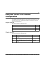
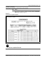
Publication history
Document
Release
Date
Description
Document
Revision 2.00
March 2001
Document Pilot Release for StormTracker-Site Manager
software.
Document
Revision 1.00
(Beta)
April 2000
Document Beta Draft to accompany Beta release of Site
Manager software.
Software Release 3.00 StormTracker-Site Manager and Administration User Guide 08-01148-01-200
vi
Software Release 3.00 StormTracker-Site Manager and Administration User Guide 08-01148-01-200
vii
Contents
About this document
xi
Audience
xi
Introducing the BitStorm™ Server software and
system applications
1-1
BitStorm Server unit and software groups
BitStorm™ Server unit
BitStorm Server software groups
Administration
BitStorm™ Server system applications
StormTracker-Site Manager carrier systems
YesWare-VBN hospitality systems
BitStorm™ Server EtherLoop system components
EtherLoop CPE modems
BitStorm™ 1900 Access Multiplexer Shelf and components
MicroBurst 4212T mini-IP DSLAM
BitStorm™ Server system installation process
Organization of this manual
1-2
1-2
1-3
1-4
1-5
1-5
1-6
1-7
1-7
1-9
1-10
1-11
1-11
StormTracker-Site Manager and Administration
software modules
2-1
Module operation and document conventions
Module operations/dialogs
Document conventions
Home
Database
EtherCraft
Downloader
SNMP
Modex Daemon
StormTracker-Spectrum Manager
BitStorm Server Administration software module
Help
2-2
2-2
2-2
2-4
2-5
2-6
2-7
2-8
2-9
2-10
2-11
2-12
Software Release 3.00 StormTracker-Site Manager and Administration User Guide 08-01148-01-200
viii Contents
BitStorm Server host network configuration
3-1
BitStorm Server
BitStorm Server functional components
Site Manager network and YesWare-VBN interfaces - ETH 0 and ETH 1
BitStorm Server console connection methods
BitStorm Server keyboard/monitor connections
BitStorm Server PC/VT-100 connection
BitStorm Server telnet connection
BitStorm Server interface: StormTracker Configuration Manager
StormTracker Configuration Manager login default
StormTracker Configuration Manager welcome screen and prompt
StormTracker Configuration Manager commands
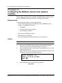
Configuring the BitStorm Server host network interface
Setting the BitStorm Server date and time
Setting the DNS nameserver(s) for the BitStorm Server
3-2
3-2
3-2
3-4
3-4
3-5
3-6
3-7
3-7
3-8
3-9
3-10
3-14
3-16
BitStorm™ Server administration
4-1
Using the Administration module
Administration / System function
Administration / License function
Using the BitStorm Server and YesWare modules for the first time
Setting up system users and passwords
Verifying the server network connection
4-2
4-3
4-7
4-8
4-11
4-12
Using the Database Module
5-1
Database module operations
Provisioning the EtherLoop modem database
Modex Daemon ETH 0 / ETH 1 interface configuration
Unmanaged vs. managed modem shelves
Provisioning EtherLoop modems
Exporting and importing EtherLoop modem databases
Using the Database / Export to File function
Using the Database / Import from File function
5-2
5-3
5-3
5-4
5-5
5-8
5-8
5-8
Software Release 3.00 StormTracker-Site Manager and Administration User Guide 08-01148-01-200
Contents ix
Using EtherCraft
6-1
EtherCraft OAM&P features
EtherLoop modem monitoring and performance management
View Logs
Privacy Mgmt
Modem management
EtherLoop modem speeds and training counts
Check Speeds
Modem Details
Client Addresses
Status
Version
Reset Modems
Log Management
Using the Get Logs function
Using the Clear Logs function
Privacy Management
Using the Privacy Mgmt feature
CO modem port management
CPE modem port management
6-2
6-2
6-3
6-3
6-4
6-4
6-7
6-8
6-12
6-13
6-14
6-15
6-16
6-16
6-17
6-18
6-18
6-19
6-20
Using the Downloader module
7-1
Downloader purpose and function
Using Downloader
Downloader status and logs
Upgrading EtherLoop modem firmware
Upgrading from Generation 1 to Generation 2 modem firmware
7-2
7-2
7-2
7-3
7-6
Software Release 3.00 StormTracker-Site Manager and Administration User Guide 08-01148-01-200
x Contents
Software Release 3.00 StormTracker-Site Manager and Administration User Guide 08-01148-01-200
xi
About this document
1-
This document describes the purpose, procedures, and requirements for using
the StormTracker-Site Manager and Administration software groups on
the BitStorm Server.
Audience
The audience for this document includes network planners, installation
technicians, network administrators, and anyone who may be charged with
provisioning or maintaining a BitStorm Server.
Software Release 3.00 StormTracker-Site Manager and Administration User Guide 08-01016-01-200
xii About this document
Software Release 3.00 StormTracker-Site Manager and Administration User Guide 08-01016-01-200
1-1
Introducing the BitStorm™ Server
software and system applications
1-
This chapter introduces BitStorm Server software groups and the system
applications for the BitStorm Server. This document covers only the
StormTracker-Site Manager and Administration software groups. Other
software residing on the BitStorm Server is covered in separate
documentation.
Chapter topic list
This chapter includes the following topics.
Topic
See
BitStorm Server unit and software groups
page 1-2
BitStorm™ Server system applications
page 1-5
BitStorm™ Server EtherLoop system components
page 1-7
BitStorm™ Server system installation process
page 1-11
Software Release 3.00 StormTracker-Site Manager and Administration User Guide 08-01148-01-200
1-2 Introducing the BitStorm™ Server software and system applications
BitStorm Server unit and software groups
The software available on a BitStorm Server depends on the system
application. The following sections introduce the BitStorm™ Server, the
software groups it supports, and the intended system applications for the
BitStorm Server and its software. References to separate documentation are
provided where necessary.
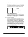
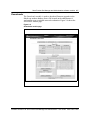
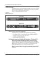
BitStorm™ Server unit
The BitStorm™ Server is the hardware platform that supports the tools for
provisioning and management used in EtherLoop™ systems and the visitorbased networks of YesWare-VBN. The BitStorm™ Server can be located in
the central communications room of the local facility or at a remote network
operating center (NOC).
Figure 1-1: BitStorm Server unit
Front View
Back View
Software Release 3.00 StormTracker-Site Manager and Administration User Guide 08-01148-01-200
Introducing the BitStorm™ Server software and system applications 1-3
BitStorm Server software groups
At a minimum, a BitStorm Server will contain the StormTracker-Site
Manager and Administration software groups covered by this document.
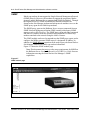
Other software groups supported by the BitStorm Server include YesWareVBN and StormTracker-Spectrum Manager. Figure 1-2 shows the
BitStorm Server "Home" page with the links to these software groups.
Figure 1-2
BitStorm Server main page
YesWare-VBN
YesWare-VBN is used to manage an EtherLoop or Ethernet Visitor-Based
Network (VBN). YesWare software modules support the following VBN
system applications:
• seamless Internet or intranet access to "visitor" end-user computers
• host site customization and service branding
• flexible options for visitor authentication and service billing
YesWare-VBN is an optional BitStorm Server component and is purchased
separately from the BitStorm Server. The YesWare Applications User Guide
contains the instructions for using the YesWare-VBN software group.
Software Release 3.00 StormTracker-Site Manager and Administration User Guide 08-01148-01-200
1-4 Introducing the BitStorm™ Server software and system applications
StormTracker-Spectrum Manager
Part of the StormSystem family of intelligent IP solutions, the StormTrackerSpectrum Manager software is used to "fine-tune" the performance of
EtherLoop modems. The StormTracker-Spectrum Manager supports the
following major functions:
• adjust EtherLoop modem signal transmission to maximize protection from
signal interference caused by other high-speed data services in the same
binder group as the EtherLoop lines
• maximize bandwidth available for EtherLoop modem signal transmission
in binder groups with no other high-speed data services
The StormTracker-Spectrum Manager software is an optional BitStorm
Server component and is purchased separately from the BitStorm Server. The
StormTracker-Spectrum Manager User Guide contains the complete
instructions for using the StormTracker-Spectrum Manager software.
StormTracker-Site Manager
Part of the StormSystem family of intelligent IP solutions, the StormTrackerSite Manager software group is used to build and manage the EtherLoop
modem database supported by the BitStorm Server in any system application.
The StormTracker-Site Manager supports the following major functions:
• automatically detect and manage all EtherLoop modems on the same LAN
segment as the BitStorm Server
• automatically detect and manage EtherLoop modems across TCP/IP LAN
or WAN segments through the appropriate EtherLoop digital subscriber
line access multiplexer (DSLAM)
• monitor the performance EtherLoop modems
• configure Simple Network Management Protocol (SNMP) support for the
modems
• upgrade modem firmware
This document contains the instructions for performing these tasks using the
StormTracker-Site Manager software group, with the exception of the
SNMP functionality. The StormTracker SNMP User Guide contains the
complete instructions for using the SNMP module and functionality.
Administration
The Administration software group is used to manage the BitStorm Server
and supports the following major functions:
• shutdown and restart the server
• upgrade the server software
• configure the server network connections
• create users and manage user access to the server
• software license management and licensing updates
This document contains the instructions for performing these tasks using the
Administration software group.
Software Release 3.00 StormTracker-Site Manager and Administration User Guide 08-01148-01-200
Introducing the BitStorm™ Server software and system applications 1-5
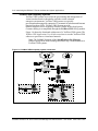
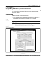
BitStorm™ Server system applications
The BitStorm™ Server can be configured to serve two types of
systems: StormTracker-Site Manager systems and YesWare-VBN
systems. The following sections describe each of these systems and illustrate
the system architectures.
StormTracker-Site Manager carrier systems
StormTracker-Site Manager carrier systems are used for the operations,
administration, management and provisioning (OAM&P) of
EtherLoop™ systems that provide service in “carrier” environments.
StormTracker-Site Manager carrier systems are used by telcos and other
Internet Service Providers (ISPs) who provide EtherLoop as a broadband
connection for their customers. The only purpose of StormTracker-Site
Manager carrier systems is to monitor and optimize the performance of the
EtherLoop modems in the system. Customer billing is accomplished
separately from the BitStorm Server software.
Figure 1-3 shows the functional architecture of a StormTracker-Site
Manager carrier system. This document covers how to use the OAM&P
capabilities of the StormTracker-Site Manager software to set up this system
architecture.
Figure 1-3: StormTracker-Site Manager carrier system architecture
Software Release 3.00 StormTracker-Site Manager and Administration User Guide 08-01148-01-200
1-6 Introducing the BitStorm™ Server software and system applications
YesWare-VBN hospitality systems
YesWare-VBN systems are used for the provisioning and management of
visitor-based networks in hospitality and other visitor-oriented
enterprise environments. YesWare-VBN systems are typically
provisioned and managed by enterprise IT personnel or subcontracted Internet
Service Providers (ISPs). YesWare-VBN systems provide
billable Internet access to temporary network visitors such as hotel guests.
Customer billing is accomplished through the YesWare-VBN Billing module.
Figure 1-4 shows the functional architecture of a YesWare-VBN system. The
YesWare-VBN Applications User Guide covers how to use the YesWare-VBN
software to provision a visitor-based network.
Note: The OAM&P functions of the StormTracker-Site Manager
software group can be used to manage the EtherLoop™ modems that serve
YesWare-VBN systems.
Figure 1-4: YesWare-VBN hospitality system architecture
Software Release 3.00 StormTracker-Site Manager and Administration User Guide 08-01148-01-200
Introducing the BitStorm™ Server software and system applications 1-7
BitStorm™ Server EtherLoop system components
The major function of the BitStorm™ Server’s StormTracker-Site Manager
software group is to provision and manage EtherLoop™ systems, whether the
EtherLoop is part of a YesWare-VBN providing billable internet service, or
strictly for managing modem performance using the StormTracker-Site
Manager.
The EtherLoop system can contain the following components:
• StormPort™ customer premise equipment (CPE) modems
• BitStorm™ 1900 Access Multiplexer Shelf and components, including
BitStorm™ DSL Access Multiplexer (DSLAM) modems
• MicroBurst 4212T mini-IP DSLAM
The following sections briefly describe each of these EtherLoop system
components.
EtherLoop CPE modems
EtherLoop CPE modems are the connection points for the end-users to the
EtherLoop system. Each EtherLoop CPE modem contains an RJ-45 port that
accepts a connection from an Ethernet 10Base-T network interface card (NIC)
on the end-user’s PC. Each CPE modem also contains standard RJ-11
interfaces to connect to the telephone and jack from the existing voice
facility phone line.
StormPort™ 400/600 Modems
The StormPort™ 400 and StormPort 600 are standalone units that support data
rates of 4 Mbps and 6 Mbps, respectively.
Figure 1-5: StormPort 400/600 CPE modem
Software Release 3.00 StormTracker-Site Manager and Administration User Guide 08-01148-01-200
1-8 Introducing the BitStorm™ Server software and system applications
StormPort™ 410/610 Modems
The StormPort™ 410 and StormPort 610 are designed to serve as a base
mount/station for an existing telephone, and also support data rates of 4
Mbps and 6 Mbps, respectively.
Figure 1-6: StormPort 410/610 CPE modem
Software Release 3.00 StormTracker-Site Manager and Administration User Guide 08-01148-01-200
Introducing the BitStorm™ Server software and system applications 1-9
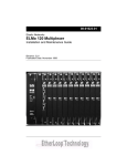
BitStorm™ 1900 Access Multiplexer Shelf and components
The BitStorm™ 1900 Access Multiplexer shelf contains the components that
control and direct data traffic between the StormPort CPE modems and the
data network. In applications requiring data and voice service, a separate
Voiceband Filter Shelf is required to split the voice traffic from the data traffic
passing through the BitStorm™ 1900 Access Multiplexer shelf.
BitStorm™ 1900 Access Multiplexer Shelf
The BitStorm™ 1900 Access Multiplexer shelves are normally installed in the
facility’s central communications room and contain the following
components:
• BitStorm™ DSLAM EtherLoop™ modems
• BitStorm™ Management Interface Unit (MIU)
• Shelf Power Card
BitStorm™ 1900 Access Multiplexer auxiliary components
Depending on the configuration, certain additional auxiliary/support
components for the BitStorm™ 1900 Access Multiplexer shelf are required.
These include the following:
• Voiceband Filter Shelf (for applications requiring voice service)
• Fan Tray (required with 6306 & 6224 DSLAM modem cards)
• Air Baffle (all configurations)
See the BitStorm™ 1900 Access Multiplexer Installation and Maintenance
Guide, 08-01101-01, for more information on auxiliary components.
Figure 1-7: BitStorm 1900 Access Multiplexer Shelf
Power Card
Modem Cards (10)
Air Baffle
MIU Card
BitStorm 1900
Access
Multiplexer
Shelf
Unused
Card
Fan Tray
Software Release 3.00 StormTracker-Site Manager and Administration User Guide 08-01148-01-200
1-10 Introducing the BitStorm™ Server software and system applications
BitStorm™ DSLAM EtherLoop™ modems
The shelf installation and cabling requirements vary for the BitStorm™ 1900
Access Multiplexer shelf depending on the BitStorm™ DSLAM EtherLoop™
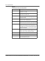
modem cards installed. The table below lists the models of the BitStorm™
DSLAM EtherLoop™ modem cards supported by the BitStorm™ 1900
Access Multiplexer shelf.
BitStorm™ DSLAM
Modem Model #
Description
4212
4 Mbps / 12 CPE modems per 1 multiplexer
6306
6 Mbps / 6 CPE modems per 1 multiplexer
6224
6 Mbps / 24 CPE modems per 1 multiplexer
BitStorm™ Management Interface Unit
The BitStorm™ Management Interface Unit (MIU) enables EtherLoop system
administrators to manage BitStorm™ 1900 Access Multiplexer shelves at
remote locations over TCP/IP WANs. To do this, the installer must configure
the BitStorm MIU onto a network accessible to the WAN. The BitStorm 1900
installation document covers how to configure the BitStorm MIU on a network
so that the shelf can be managed by the system administrator.
MicroBurst 4212T mini-IP DSLAM
MicroBurst™ 4212T mini-IP DSLAM is a one rack unit IP DSLAM that
supports up to 12 EtherLoop CPE modems at 4 Mbps. The MicroBurst™ has
built-in voiceband filtering capability and is environmentally hardened for
applications such as digital loop carriers and other outside plant devices
requiring high-speed access functionality or in low density applications.
The MicroBurst™ is well suited for the outside plant applications where heat
dissipation and powering requirements inhibit deployment of conventional
ATM-based DSL solutions. This is because of the low power consumption and
low heat dissipation of EtherLoop IP DSL burst mode enabled systems. The
first generation of the MicroBurst™ includes a single T-1 interface and
Ethernet for interfacing to high capacity Gigabit Ethernet backhaul systems.
Future evolution will include multi-T-1 and optical solutions.
Figure 1-8: MicroBurst 4212T mini-IP DSLAM
Software Release 3.00 StormTracker-Site Manager and Administration User Guide 08-01148-01-200
Introducing the BitStorm™ Server software and system applications 1-11
BitStorm™ Server system installation process
The process of installing a Bitstorm™ Server system, in broad terms, includes
the following:
1 Install the TCP/IP Ethernet local host LAN/WAN network to support the
BitStorm Server connection (if none existing).
2 Install the EtherLoop and/or Ethernet infrastructure.
3 Configure the BitStorm Server on an existing local host LAN/WAN.
4 Set up BitStorm Server administration.
5 Provision the EtherLoop infrastructure to support StormTracker-Site
Manager OAM&P
6 Provision YesWare-VBN services.
This manual covers steps 3 through 5 of the BitStorm™ Server system
installation process. The YesWare-VBN Applications User Guide contains the
provisioning requirements for YesWare-VBN systems.
Organization of this manual
This document provides procedures for setting up the BitStorm Server on the
local host network and for provisioning the EtherLoop system infrastructure.
In general, the information is presented in the order in which you will need to
use it.
Software Release 3.00 StormTracker-Site Manager and Administration User Guide 08-01148-01-200
1-12 Introducing the BitStorm™ Server software and system applications
Software Release 3.00 StormTracker-Site Manager and Administration User Guide 08-01148-01-200
2-1
StormTracker-Site Manager and
Administration software modules
2-
This introduces the purpose and function of the StormTracker-Site Manager
and Administration software modules.
Chapter topic list
This chapter includes the following topics.
Topic
See
Module operation and document conventions
page 2-2
Home
page 2-4
Database
page 2-5
EtherCraft
page 2-6
Downloader
page 2-7
SNMP
page 2-8
Modex Daemon
page 2-9
StormTracker-Spectrum Manager
page 2-10
BitStorm Server Administration software module
page 2-11
Help
page 2-12
Software Release 3.00 StormTracker-Site Manager and Administration User Guide 08-01148-01-200
2-2 StormTracker-Site Manager and Administration software modules
Module operation and document conventions
This section describes basic operation of the BitStorm™ Server software and
the conventions used in this document for describing the software operations.
The remainder of this chapter describes the purpose and function of the
StormTracker-Site Manager and Administration modules covered by this
document.
Module operations/dialogs
Software "modules" are used to provision and manage the BitStorm™ Server
system. Module pages contain a variety of "operations" such as the CO
Add/Search operation used to manually provision EtherLoop CO modems.
Software operations are executed through "dialogs."
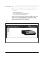
Figure 2-1 shows the module buttons on the StormTracker-Site Manager main
menu.
Figure 2-1
StormTracker-Site Manager module buttons
Document conventions
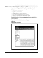
In this document, module names are italicized, operation link names are
underlined, and dialog names are in "quotation marks." Figure 2-2 on page 2-3
shows the Database module as an example.
Software Release 3.00 StormTracker-Site Manager and Administration User Guide 08-01148-01-200
StormTracker-Site Manager and Administration software modules 2-3
Figure 2-2
Database module operations and dialogs
Database module
CO Add/Search operation
"CO Modem Configuration" dialog linked to CO Add/Search operation
Software Release 3.00 StormTracker-Site Manager and Administration User Guide 08-01148-01-200
2-4 StormTracker-Site Manager and Administration software modules
Home
The Home module page contains the links to the four software groups that
reside on the BitStorm Server.
Figure 2-3 shows the Home module page with the four software groups.
Note: The Home module page on non-YesWare-VBN systems will not
have the link to the YesWare-VBN software group.
Figure 2-3
Home module page
Software Release 3.00 StormTracker-Site Manager and Administration User Guide 08-01148-01-200
StormTracker-Site Manager and Administration software modules 2-5
Database
The Database module is used to discover and provision EtherLoop™ CO and
CPE modems and their associated ports. In addition, this module contains the
operations to export/import EtherLoop™ databases and provision IP DSLAM
shelves containing IP-manageble interfaces. Figure 2-4 shows the Database
module page.
Figure 2-4
Database module page
Software Release 3.00 StormTracker-Site Manager and Administration User Guide 08-01148-01-200
2-6 StormTracker-Site Manager and Administration software modules
EtherCraft
The EtherCraft module is used to control and monitor EtherLoop modems
from a remote PC/workstation using a Web browser. EtherCraft can be used to
check modem status and monitor performance, set privacy filters, enable and
disable CO/CPE modem ports, and get and clear logs. Figure 2-5 shows the
EtherCraft module page.
Figure 2-5
EtherCraft module page
Software Release 3.00 StormTracker-Site Manager and Administration User Guide 08-01148-01-200
StormTracker-Site Manager and Administration software modules 2-7
Downloader
The Downloader module is used to download firmware upgrades to the
EtherLoop modem database from a file located on the administrator’s
workstation or on a reachable network workstation. Figure 2-6 shows the
Downloader module page.
Figure 2-6
Downloader module page
Software Release 3.00 StormTracker-Site Manager and Administration User Guide 08-01148-01-200
2-8 StormTracker-Site Manager and Administration software modules
SNMP
EtherLoop modems do not support the Simple Network Management Protocol
(SNMP) directly. However, the modems do support the proprietary Modex
protocol, and the BitStorm Server supports both SNMP and Modex. Through
the BitStorm Server’s SNMP and the Modex Daemon functions, the
StormTracker-Site Manager implements both protocols and thus serves as the
SNMP proxy agent for the EtherLoop modems.
The SNMP proxy agent on the BitStorm Server accepts commands from an
SNMP Network Management Station (NMS) running a third-party SNMP
manager such as HP OpenView. The SNMP proxy agent takes the commands
and retrieves statistics about the operation and performance of EtherLoop
modems attached to the network using the Modex Daemon.
The SNMP module can be used to startand stop the SNMP proxy agent, and to
configure the MIB to generate SNMP traps to a designated IP address. In
addition, the SNMP Browser operation can be used to query the StormTrackerSite Manager database for EtherLoop modem information.
Figure 2-7 shows the SNMP module page.
Note: This document does not cover the usage requirements for SNMP on
the BitStorm Server. See the BitStorm Server SNMP User Guide for more
information on using the StormTracker-Site Manager’s SNMP
capabilities.
Figure 2-7
SNMP module page
Software Release 3.00 StormTracker-Site Manager and Administration User Guide 08-01148-01-200
StormTracker-Site Manager and Administration software modules 2-9
Modex Daemon
The Modex Daemon module controls all direct communication between the
EtherLoop modems and the BitStorm Server. It is started at bootup and runs
continuously. The daemon executes functions on the EtherLoop modems such
as the following:
• SNMP get/set commands
• EtherCraft modem status polling and controls
• EtherLoop modem firmware downloads
The Modex Daemon module contains operations to start and stop the daemon
without having to re-start the BitStorm Server, and to configure which
BitStorm Server interface (ETH 0 or ETH 1) the Modex daemon will use.
Figure 2-8 shows the Modex Daemon module page.
Figure 2-8
Modex Daemon module page
Software Release 3.00 StormTracker-Site Manager and Administration User Guide 08-01148-01-200
2-10 StormTracker-Site Manager and Administration software modules
StormTracker-Spectrum Manager
As mentioned in Chapter 1, the Spectrum Manager module is used to adjust
EtherLoop modem signal transmission to maximize protection from
EtherLoop signal interference, and/or to maximize bandwidth available for
EtherLoop modem signal transmission.
The StormTracker-Spectrum Manager software is an optional BitStorm
Server component and is purchased separately from the BitStorm Server, and
is not covered by this document. The StormTracker-Spectrum Manager User
Guide contains the complete instructions for using the StormTrackerSpectrum Manager software.
Figure 2-9 shows the Spectrum Manager module page. This module is
accessible through either the BitStorm Server Home module page or through
the Spectrum Manager module button in the StormTracker-Site Manager
module group.
Figure 2-9
Spectrum Manager module page
Software Release 3.00 StormTracker-Site Manager and Administration User Guide 08-01148-01-200
StormTracker-Site Manager and Administration software modules 2-11
BitStorm Server Administration software module
As mentioned in Chapter 1, the BitStorm Server Administration software is
used to manage the BitStorm Server and supports the following major
functions:
• shutdown and restart the server
• upgrade the server software
• configure the server network connections
• create users and manage user access to the server
• software license management and licensing updates
The Administration software currently consists of a single module. This
module is accessible by clicking the Administration link the BitStorm Server
Home module page.
Figure 2-10 shows the Administration module page.
Figure 2-10
Administration module page
Software Release 3.00 StormTracker-Site Manager and Administration User Guide 08-01148-01-200
2-12 StormTracker-Site Manager and Administration software modules
Help
The Help module contains information on all tasks done using the BitStorm
Server software.
Figure 2-8 shows an example help topic on a Help module page.
Figure 2-11
Help module page
Software Release 3.00 StormTracker-Site Manager and Administration User Guide 08-01148-01-200
3-1
BitStorm Server host network
configuration
3-
This chapter describes the methods for connecting to the BitStorm Server and
using the StormTracker Configuration Manager to configure the BitStorm
Server on the host network.
Chapter topic list
This chapter includes the following topics.
Topic
See
BitStorm Server
page 3-2
BitStorm Server console connection methods
page 3-4
BitStorm Server interface: StormTracker Configuration Manager
page 3-7
Chapter task list
This section includes the following tasks.
Procedure
Task
See
3-1
Configuring the BitStorm Server host network
interface
page 3-10
3-2
Setting the BitStorm Server date and time
page 3-14
3-3
Setting the DNS nameserver(s) for the BitStorm page 3-16
Server
Software Release 3.00 StormTracker-Site Manager and Administration User Guide 08-01148-01-200
3-2 BitStorm Server host network configuration
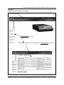
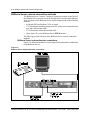
BitStorm Server
The BitStorm Server is used to provision and manage services to the YesWare
system infrastructure and clients. The BitStorm Server resides as a standard
"host" on a local TCP/IP Ethernet host network.
Figure 3-1 shows the BitStorm Server unit.
Figure 3-1
BitStorm Server unit
Front View
Back View
BitStorm Server functional components
The BitStorm Server unit has the following functional components:
• two Ethernet 10Base-T network interface cards (ETH 0 and ETH 1)
• two RS-232 serial ports (COM1 and COM2)
• 110/120 V AC power connector
• monitor and keyboard connectors
Site Manager network and YesWare-VBN interfaces - ETH 0 and ETH 1
The two Ethernet 10/100 Base-T network interface cards (NICs) in the
BitStorm Server (ETH 0 and ETH 1) provide the connectivity for the
YesWare-VBN to access the Internet through a host network. The ETH 0
interface connects the BitStorm Server to the Site Manager host network. The
ETH 1 interface connects visitors on YesWare’s Visitor-Based Network
(VBN) to the BitStorm Server for access to YesWare services.
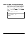
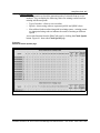
Figure 3-2 on page 3-3 shows the component connections on the back of the
BitStorm Server unit. Table 3-1 on page 3-3 describes the function of each
component.
Software Release 3.00 StormTracker-Site Manager and Administration User Guide 08-01148-01-200
BitStorm Server host network configuration 3-3
Figure 3-2
BitStorm Server connections
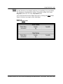
Table 3-1
BitStorm Server component connector functions
BitStorm Server Connector
Description/Function
Primary Power Switch
Controls power to unit. Secondary switch on front used as reset.
AC Power Connector
110/120 V AC input.
Keyboard
Standard PS2 keyboard interface.
USB Connector (not used)
Universal Serial Bus (USB) device interface.
COM 1
RS232 serial interface to Property Management System (PMS) or
serial printer.
COM 2
RS232 serial interface for VT-100 terminal (or terminal emulator) used
with BitStorm Server console interface.
Mouse (not used)
PS2 mouse interface.
Printer Port (not used)
Parallel printer interface.
Monitor
15-pin D-Sub monitor interface for VGA, SVGA or later model.
Modem (not used)
Analog modem connector
ETH 0
Ethernet 10/100Base-T interface to host network (LAN or WAN).
ETH 1
Ethernet 10/100Base-T interface to YesWare’s InterProxy clients.
Software Release 3.00 StormTracker-Site Manager and Administration User Guide 08-01148-01-200
3-4 BitStorm Server host network configuration
BitStorm Server console connection methods
The BitStorm Server "console" consists of connectors located on the back of
the BitStorm Server used to access the StormTracker Configuration Manager.
You can connect to the BitStorm Server console using any one of the following
methods:
• keyboard (PS2) and monitor (VGA or better)
• VT-100 terminal emulation program on a PC with a serial communications
port and a null-modem cable
• VT-100 terminal with a null-modem cable
• telnet from a PC to the BitStorm Server ETH 0 interface
The following sections illustrate these BitStorm Server console connection
methods.
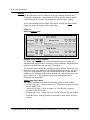
BitStorm Server keyboard/monitor connections
Figure 3-3 shows the method for connecting a keyboard/monitor combination
to the BitStorm Server.
Figure 3-3
BitStorm Server keyboard/monitor connections
Software Release 3.00 StormTracker-Site Manager and Administration User Guide 08-01148-01-200
BitStorm Server host network configuration 3-5
BitStorm Server PC/VT-100 connection
Figure 3-4 shows the method for connecting a PC with a VT-100 terminal
emulator or a VT-100 terminal to the BitStorm Server serial port (COM 2).
Table 3-2 lists the COM 2 VT-100 terminal communication settings.
Table 3-2
COM 2 VT100 terminal communication settings
Setting
Value
Baud Rate
9600
Start Bits
8
Parity
None
Stop Bits
1
Figure 3-4
BitStorm Server PC or VT-100 terminal console connection
Software Release 3.00 StormTracker-Site Manager and Administration User Guide 08-01148-01-200
3-6 BitStorm Server host network configuration
BitStorm Server telnet connection
For the initial configuration of the BitStorm Server, you can telnet to the
StormTracker Configuration Manager by connecting directly to the ETH 0
interface using a Category 5 cross-over cable. You can also telnet to the
StormTracker Configuration Manager over an existing network connection to
the ETH 0 interface to change configuration settings. Figure 3-5 on page 3-6
shows the methods for connecting to the StormTracker Configuration
Manager over telnet.
CAUTION - Possible network conflict
The BitStorm Server ETH 0 interface has a default TCP/IP address configuration
which could conflict with the host network. DO NOT connect the ETH 0 interface to
a host network until you have re-configured the ETH 0 interface with a TCP/IP
configuration that is valid for the host network.
Figure 3-5
BitStorm Server telnet connections
Telnet / Direct PC-toBitStorm Server
connection
Telnet / Network-toBitStorm Server
connection
Software Release 3.00 StormTracker-Site Manager and Administration User Guide 08-01148-01-200
BitStorm Server host network configuration 3-7
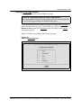
BitStorm Server interface: StormTracker Configuration Manager
The BitStorm Server console interface is called the StormTracker
Configuration Manager, a command-based interface used to configure the
BitStorm Server on the host network. The StormTracker Configuration
Manager can also be used to conduct low-level system diagnostics such as
"ping" tests and to view route-table and ETH 0/ETH 1 port assignments.
StormTracker Configuration Manager login default
Figure 3-6 shows the "login" prompt of the StormTracker Configuration
Manager. The default login name is admin and the password is etherloop
(case-sensitive).
Figure 3-6
StormTracker Configuration Manager login prompt
Software Release 3.00 StormTracker-Site Manager and Administration User Guide 08-01148-01-200
3-8 BitStorm Server host network configuration
StormTracker Configuration Manager welcome screen and prompt
Figure 3-7 shows the"Welcome" screen and OSM># prompt you should see
after entering the login name and password. Table 3-3 on page 3-9 lists and
defines the commands available in the StormTracker Configuration Manager.
Procedure 3-1 on page 3-10 describes the procedure for using the
StormTracker Configuration Manager to configure BitStorm Server on the
host network.
Figure 3-7
StormTracker Configuration Manager Welcome screen and command prompt
Software Release 3.00 StormTracker-Site Manager and Administration User Guide 08-01148-01-200
BitStorm Server host network configuration 3-9
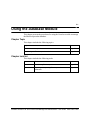
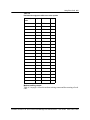
StormTracker Configuration Manager commands
Table 3-3 lists the StormTracker Configuration Manager commands used to
configure the BitStorm Server.
Table 3-3
StormTracker Configuration Manager commands
Command
Function
Syntax
help
Displays this list of commands.
help
route
Display BitStorm Server routing table.
route
port
Display BitStorm Server ETH 0 and ETH 1 port
settings.
port
ping
Test basic communications between the BitStorm
Server, client computers, and the host network.
ping [IP address or DNS name]
passwd
passwd
Change admin user password. For security
purposes, use this command to change the default
password after the first login.
configure
Configure the ETH 0 interface network IP address, configure
gateway, BitStorm Server host name (see
See Procedure 3-1 on page 3-10.
nameserver command below), and time zone.
nameserver Specify the IP address of the nameserver the
BitStorm Server will use.
(optional)
nameserver
(displays current nameserver
settings)
nameserver [front/last/del]
(adds or deletes nameservers)
date
Display and set system date and time
date
reboot
Shut down and re-start the BitStorm Server. Always reboot
use this command or the Web interface to re-boot
the BitStorm Server. Never use only the power
switch for a re-boot, as an uncontrolled
shutdown/re-start could corrupt the StormTracker
Configuration Manager software.
shutdown
Shut down the BitStorm Server. Always use this
command or the Web interface to shut down the
BitStorm Server. Never use only the BitStorm
Server power switch for a shutdown.
exit
exit
Close the StormTracker Configuration Manager
and exit to the login prompt. To prevent
unauthorized access to the BitStorm Server,
always use this command after configuration tasks
are done.
timezone
Change the time zone used by the BitStorm Server. timezone
shutdown
Software Release 3.00 StormTracker-Site Manager and Administration User Guide 08-01148-01-200
3-10 BitStorm Server host network configuration
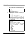
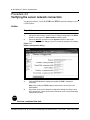
Procedure 3-1
Configuring the BitStorm Server host network
interface
This procedure explains how to configure the BitStorm Server host network
interface (ETH 0) using the StormTracker Configuration Manager.
Requirements
To perform this procedure, you need the following:
•
valid TCP/IP configuration for the BitStorm Server ETH 0 network
interface, including the following:
— IP address
— network mask (subnet) address
— network gateway address
•
•
•
host name for the BitStorm Server
DNS nameserver IP address
time zone information for the BitStorm Server host network
Action
Step Action
1
Connect to the YesWare console using one of the methods described in
“BitStorm Server console connection methods” on page 3-4.
2
Connect the BitStorm Server power plug to an appropriate power source, and
flip the power switch ON.
After the BitStorm Server completes its power-on initialization sequence, the
YesWare login prompt should appear as follows:
3
Enter the BitStorm Server login name and password.
—continued—
Software Release 3.00 StormTracker-Site Manager and Administration User Guide 08-01148-01-200
BitStorm Server host network configuration 3-11
Procedure 3-1 (continued)
Configuring the BitStorm Server host network interface
Step Action
The StormTracker Configuration Manager "welcome" screen and command
prompt appear as shown in Figure 3-8.
Figure 3-8
StormTracker Configuration Manager "welcome" screen
4
At the command prompt (OSM#>), type configure and press <ENTER>. The
system displays the following:
5
Enter the valid host network IP address assigned to the BitStorm Server ETH
0 network interface. The system should appear similar to the following:
—continued—
Software Release 3.00 StormTracker-Site Manager and Administration User Guide 08-01148-01-200
3-12 BitStorm Server host network configuration
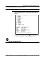
Procedure 3-1 (continued)
Configuring the BitStorm Server host network interface
Step Action
6
Enter the valid network mask (subnet) address assigned to the BitStorm
Server ETH 0 network interface. The system should appear similar to the
following:
7
Enter the valid gateway IP address assigned to the BitStorm Server ETH 0
network interface. The system should appear similar to the following:
8
Enter the host name assigned to the BitStorm Server ETH 0 network
interface. If the BitStorm Server will use the Domain Name System (DNS),
the BitStorm Server must have a valid DNS host name. The system should
appear similar to the following:
—continued—
Software Release 3.00 StormTracker-Site Manager and Administration User Guide 08-01148-01-200
BitStorm Server host network configuration 3-13
Procedure 3-1 (continued)
Configuring the BitStorm Server host network interface
Step Action
9
Select the time zone from the list in which the BitStorm Server resides, and
enter the corresponding number. The system should appear similar to the
following:
10
If the configuration settings are correct, type y and press <ENTER>.
Go to Procedure 3-2 on page 3-14 to set the system date and time, and
Procedure 3-3 on page 3-16 to configure the DNS nameserver.
STOP
You have completed this task.
Software Release 3.00 StormTracker-Site Manager and Administration User Guide 08-01148-01-200
3-14 BitStorm Server host network configuration
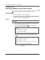
Procedure 3-2
Setting the BitStorm Server date and time
This procedure explains how to use the StormTracker Configuration Manager
date command to set the date and time for the BitStorm Server.
Requirements
To perform this procedure, you need the following:
•
a connection to the BitStorm Server ETH 0 network interface using one of
the methods described in “BitStorm Server console connection methods”
on page 3-4. host name for the BitStorm Server
Action
Step Action
1
Login to the BitStorm Server (the steps for logging into the BitStorm Server
are presented in Procedure 3-1 on page 3-10).
2
At the command prompt (OSM#>), type date and press <ENTER>. The
system should appear similar to the following:
3
Type y and press <ENTER>. The system should appear similar to the
following:
—continued—
Software Release 3.00 StormTracker-Site Manager and Administration User Guide 08-01148-01-200
BitStorm Server host network configuration 3-15
Procedure 3-2 (continued)
Setting the BitStorm Server date and time
Step Action
4
Enter the system date and local time. The system should appear similar to
the following:
STOP
You have completed this task.
Software Release 3.00 StormTracker-Site Manager and Administration User Guide 08-01148-01-200
3-16 BitStorm Server host network configuration
Procedure 3-3
Setting the DNS nameserver(s) for the BitStorm
Server
Use this procedure to identify the DNS nameserver used by the BitStorm
Server. The StormTracker Configuration Manager nameserver command can
be used to display, add or delete the IP address(es) of the DNS nameserver(s)
supporting the BitStorm Server. Nameserver addresses can be added to the
beginning or the end of the nameserver list. This procedure describes each of
these command capabilities.
Requirements
To perform this procedure, you need the following:
•
•
a connection to the BitStorm Server ETH 0 network interface using one of
the methods described in “BitStorm Server console connection methods”
on page 3-4. host name for the BitStorm Server
a valid DNS nameserver IP address
Valid host and domain name required
The BitStorm Server must also have a valid DNS host/domain name
(host.domain.domain) defined using the StormTracker Configuration Manager
configure command. See Procedure 3-1 on page 3-10.
Action
Step Action
1
Login to the BitStorm Server (the steps for logging into the BitStorm Server
are presented in Procedure 3-1 on page 3-10).
2
To display the existing nameserver addresses, type nameserver at the
command prompt (OSM#>), and press <ENTER>. The system should
appear similar to the following:
—continued—
Software Release 3.00 StormTracker-Site Manager and Administration User Guide 08-01148-01-200
BitStorm Server host network configuration 3-17
Procedure 3-3 (continued)
Setting the DNS nameserver(s) for the BitStorm Server
Step Action
3
To add a nameserver to the beginning of the list of existing nameserver
addresses, type nameserver front at the command prompt (OSM#>), and
press <ENTER>. The system should appear similar to the following:
4
To add a nameserver to the end of the list of existing nameserver addresses,
type nameserver last at the command prompt (OSM#>), and press
<ENTER>. The system should appear similar to the following:
5
To remove a nameserver from the list of existing nameserver addresses, type
nameserver del at the command prompt (OSM#>), and press <ENTER>. The
system should appear similar to the following:
STOP
You have completed this task.
Software Release 3.00 StormTracker-Site Manager and Administration User Guide 08-01148-01-200
3-18 BitStorm Server host network configuration
Software Release 3.00 StormTracker-Site Manager and Administration User Guide 08-01148-01-200
4-1
BitStorm™ Server administration
4-
This chapter describes the operations of the Administration module and the
procedures to prepare and verify the settings in the BitStorm Server software
to support .
Chapter topic list
This chapter includes the following topics.
Topic
See
Using the Administration module
page 4-2
Chapter task list
This chapter includes the following tasks.
Procedure
Task
See
4-1
Using the BitStorm Server and YesWare modules for page 4-8
the first time
4-2
Setting up system users and passwords
page 4-11
4-3
Verifying the server network connection
page 4-12
Software Release 3.00 StormTracker-Site Manager and Administration User Guide 08-01148-01-200
4-2 BitStorm™ Server administration
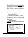
Using the Administration module
The Administration software is used to manage the BitStorm Server.
• create users and manage user access to the server
• software license management and licensing updates
Figure 4-1 shows the Administration main page. The following sections cover
the user requirements to perform the Administration operations.
Figure 4-1: Administration main page
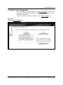
Software Release 3.00 StormTracker-Site Manager and Administration User Guide 08-01148-01-200
BitStorm™ Server administration 4-3
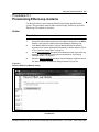
Administration / System function
The System function of the Administration software group supports the
following operations:
• Install/Upgrade
• Restart System
• Shutdown
• Network
The table below describes each of these operations.
Operation
Description
Install/Upgrade
Upgrade the software mofules on the BitStorm Server.
Restart System
Restart the BitStorm Server.
Shutdown
Shutdown the BitStorm Server.
Network
View and/or modfy the network configuration
Install/Upgrade page
Figure 4-2 shows the Install/Upgrade page. System administrators must obtain
an upgrade load file from Elastic Networks, and load the file on a local
workstation. The administrator then use this screen to browse to the upgrade
file and use it to upgrade the software modules on the BitStorm Server. This
operation does not upgrade the EtherLoop modem firmware.
Figure 4-2: Install/Upgrade page
Software Release 3.00 StormTracker-Site Manager and Administration User Guide 08-01148-01-200
4-4 BitStorm™ Server administration
Restart System page
Figure 4-3 shows the Restart System page. System administrators should
always use this command or the equivalent in the StormTracker-Configuration
Manager to restart the BitStorm Server. If at all possible, never use only the
power switch to restart the BitStorm Server, as this could corrupt the unit’s file
system.
Figure 4-3: Restart System page
Shutdown page
Figure 4-4 shows the Shutdown page. System administrators should always
use this command or the equivalent in the StormTracker-Configuration
Manager to shutdown the BitStorm Server. If at all possible, never use only the
power switch to shutdown the BitStorm Server, as this could corrupt the unit’s
file system.
Figure 4-4: Shutdown page
Software Release 3.00 StormTracker-Site Manager and Administration User Guide 08-01148-01-200
BitStorm™ Server administration 4-5
Network page
Figure 4-5 shows the Network page. System administrators should always use
this command or the equivalent in the StormTracker-Configuration Manager
to shutdown the BitStorm Server. If at all possible, never use only the power
switch to shutdown the BitStorm Server, as this could corrupt the unit’s file
system.
Figure 4-5: Network page
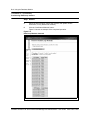
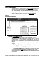
Table 4-1 defines each of the entries in the Network page.
Table 4-1: Network Configuration page
Field
Description
Hostname
The host name given by the LAN administrator to the BitStorm Server on
the host network.
IP Address - primary port
(eth0)
ETH 0 is the BitStorm Server’s interface to the host LAN. This field is the IP
address given by the LAN administrator to the BitStorm Server on the host
network.
Network Mask - primary port The Network Mask for ETH 0 is given by the LAN administrator to the
(eth0)
BitStorm Server on the host network.
Gateway Address
The Network Mask given by the LAN administrator to the BitStorm Server
on the host network.
IP Address - secondary port ETH 1 is the BitStorm Server’s interface to the YesWare-VBN. This field is
(eth1)
the VBN IP address assigned by the BitStorm Server administrator.
Network Mask - secondary
port (eth1)
This field is the VBN Network Mask assigned by the BitStorm Server
administrator.
Software Release 3.00 StormTracker-Site Manager and Administration User Guide 08-01148-01-200
4-6 BitStorm™ Server administration
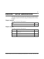
Administration / User Administration function
The User Administration function of the Administration software group
supports the following operations:
• Add User
• Change Password
• Reset Password
• Delete User
The table below describes each of these operations.
Operation
Description
Add User
Add new user accounts to the BitStorm Server.
Change Password
Change the password of the active user (your own).
Reset Password
Change the password of the other users.
Delete User
Delete user accounts to the BitStorm Server.
The BitStorm Server administrator should use the the Change Password
operation to change the manager/manager login/password immediately after
the first use of the system. Also, note that the BitStorm Server has no method
of tracking user accounts and passwords. Records of accounts and passwords
must be kept separate from the BitStorm Server.
Software Release 3.00 StormTracker-Site Manager and Administration User Guide 08-01148-01-200
BitStorm™ Server administration 4-7
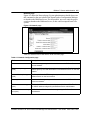
Administration / License function
The License function of the Administration software group is used when new
software is purchased for the BitStorm Server as an "add-on," and the License
agreement needs to be updated. For example, if an administrator might
purchase YesWare-VBN software for a BitStorm Server that previously had
only StormTracker-Site Manager. For the YesWare-VBN software to become
functional, the administrator would have to come to the License / Update page,
scroll down to the bottom of the License Agreement, click the "Update"
button, and enter the new License Key.
Figure 4-6 shows the License / Update page.
Figure 4-6: License / Update page
Software Release 3.00 StormTracker-Site Manager and Administration User Guide 08-01148-01-200
4-8 BitStorm™ Server administration
Procedure 4-1
Using the BitStorm Server and YesWare modules for
the first time
This procedure contains the requirements and steps involved in using YesWare
for the first time.
Requirements
This section describes the requirements for accessing the YesWare web
interface.
Connecting to the ETH 0 interface
To access the YesWare web interface, you must have access to the network
where the BitStorm Server ETH 0 interface resides. This can be done with a
PC connected over a network, internetwork, simple passive hub, or through a
direct connection to the BitStorm Server ETH 0 interface. See Chapter 3 for
more information.
Direct PC connection to ETH 0
To connect a PC directly to the ETH 0 interface, a Category 5 Ethernet crossover
cable must be used and the PC must be configured as a TCP/IP node on the same
LAN and subnet as the ETH 0 interface.
Browsing to the ETH 0 URL
All YesWare modules are web-based, and are launched by browsing to the IP
address configured for the BitStorm Server ETH 0 network interface. Before
using the YesWare modules described in this manual, you must know the IP
address configured for the ETH 0 interface.
BitStorm Server default-configured ETH 0 IP address
To access the BitStorm Server, use the IP address configured using the console
interface (see Chapter 3) or the default-configured ETH 0 address.
The BitStorm Server is configured before shipping with the following ETH 0 IP
address: 192.168.1.2
Finding an unknown ETH 0 IP address configuration
If the IP configuration set for ETH 0 is unknown, login to the StormTracker
Configuration Manager and use the port command to display the ETH 0
settings (ETH 1 values are also displayed). See Chapter 3 for a description of
the port command.
Note: The VT-100 may need to be adjusted to increase the window size
("buffer" setting) in order to see all the port data.
—continued—
Software Release 3.00 StormTracker-Site Manager and Administration User Guide 08-01148-01-200
BitStorm™ Server administration 4-9
Procedure 4-1 (continued)
Using the BitStorm Server and YesWare modules for the first time
Action
Step Action
1
Launch the PC web browser (Internet Explorer or Netscape Navigator).
2
Specify the ETH 0 Universal Resource Locator (URL),
Note: The URL must include the ETH 0 IP address followed by the
"yesware/jsp/" directory, as in the following example (for a BitStorm Server at
ETH 0 IP address 10.255.254.2):
10.255.254.2/YesWare/jsp/
The "YesWare" in the URL is case-sensitive (Y/W, not y/w). Also, if the
"/YesWare/jsp/" is not included in the ETH 0 URL, the system will return a
denial of access. If the ETH 0 URL is entered correctly, the BitStorm Server
Home page appears.
3
Click the Administration link to launch the the licensing agreement page.
4
Read the licensing agreement and click the "Accept" button. The "Store
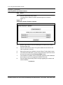
License Key" dialog appears as shown in Figure 4-7.
Figure 4-7
Store License Key dialog
5
Enter the 20-digit license key shipped with the server and click the "Store"
button.
—continued—
Software Release 3.00 StormTracker-Site Manager and Administration User Guide 08-01148-01-200
4-10 BitStorm™ Server administration
Procedure 4-1 (continued)
Using the BitStorm Server and YesWare modules for the first time
Step Action
At this point, you have access to the Administration and StormTracker-Site
Manager software groups. If you close your browser and later try to return to
the Administration or StormTracker-Site Manager software groups, a login
dialog appears as shown in :
Web interface login user name and password default
The default-configured user name/password login for all BitStorm Server
software groups is manager/manager.
Figure 4-8
Administration and StormTracker-Site Manager Login dialog
6
To access the YesWare group, click the Home module button and select the
YesWare link on the Home page. The YesWare login dialog appears as
shown in Figure 4-9.
Figure 4-9
YesWare Login dialog
STOP
You have completed this task.
Software Release 3.00 StormTracker-Site Manager and Administration User Guide 08-01148-01-200
BitStorm™ Server administration 4-11
Procedure 4-2
Setting up system users and passwords
Use this procedure to create users and change/add passwords for the system.
Action
Step Action
1
Using a PC web browser, browse to the IP address configured for the ETH 0
interface, and login to the Administration software group.
2
Use the operations in the User Administration function add users and
change passwords as required by your system. Figure 4-11 shows an
example of the "Add New User Account" dialog.
Note: Use the Change Password operation to change the manager/manager
login/password immediately after the first use of the system. The Reset
Password operation is used to change the passwords of other users in the
system.
Figure 4-10
Add New User Account dialog
3
Record the user account information according to local office procedures.
STOP
You have completed this task.
Software Release 3.00 StormTracker-Site Manager and Administration User Guide 08-01148-01-200
4-12 BitStorm™ Server administration
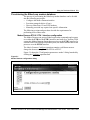
Procedure 4-3
Verifying the server network connection
Use this procedure to verify the ETH 0 and ETH 1 network settings to serve
a VBN system.
Action
Step Action
1
Using a PC web browser, browse to the IP address configured for the ETH 0
interface, and login to the Administration software group.
2
Select the Network operation from the System function to launch the
"Network Configuration" dialog. Figure 4-11 shows an example of this dialog.
Figure 4-11
Network Configuration dialog
3
Verify the ETH 0 network settings and modify the ETH 1 settings as
necessary.
Note: Only modify the ETH 0 settings if instructed to do so by the LAN
administrator.
4
Record the values in the "Network Configuration" dialog according to local
office procedures. These values will be needed for some of the provisioning
tasks performed later.
STOP
You have completed this task.
Software Release 3.00 StormTracker-Site Manager and Administration User Guide 08-01148-01-200
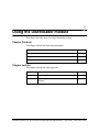
5-1
Using the Database Module
5-
This chapter presents the procedures for using the Database module to manage
the EtherLoop modem database.
Chapter Topic
This chapter includes the following topics.
Topic
See
Database module operations
page 5-2
Provisioning the EtherLoop modem database
page 5-3
Chapter task list
This chapter includes the following tasks.
Procedure
Task
See
5-1
Provisioning EtherLoop modems
page 5-5
5-2
Exporting and importing EtherLoop modem
databases
page 5-8
Software Release 3.00 StormTracker-Site Manager and Administration User Guide 08-01148-01-200
5-2 Using the Database Module
Database module operations
The Database module contains the operations used to create and manage the
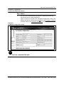
EtherLoop modem database. Table 5-1 summarizes the purpose of these
operations in the Database module.
Table 5-1
Servers and Proxies module functions
Function name
Operation purpose
Discover Modems
This operation is used to automatically detect all EtherLoop
modems in the BitStorm Server system.
Validate DB
This operation is used to verify that all EtherLoop CPE
modems in the BitStorm Server system have valid information
in the database (no duplicate locations or CO modem ports,
etc.).
Clear DB
This operation is used to clear all EtherLoop modem
information in the BitStorm Server system database.
CO Add/Search
This operation is used to manually add EtherLoop CO
modems to the database and to search for previously
provisioned CO modems.
CO View/Edit
This operation is used to view all CO modem information in
the database and to manually provision/edit site-specific
information.
CPE Add/Search
This operation is used to manually add EtherLoop CPE
modems to the database and to search for previously
provisioned CPE modems.
CPE View/Edit
This operation is used to view all CPE modem information in
the database and to manually provision/edit site-specific
information.
Shelf Add/Search
This operation is used to provision the IP addresses of
manageable EtherLoop modem shelves and to search for
previously provisioned shelves.
Shelf View/Edit
This operation is used to view the provisioned EtherLoop
modem shelves and to edit the shelf information.
Export to File
This operation is used to export the EtherLoop database to a
comma-separated value (CSV) file.
Import from File
This operation is used to import the EtherLoop database from
a previously exported CSV database file.
Software Release 3.00 StormTracker-Site Manager and Administration User Guide 08-01148-01-200
Using the Database Module 5-3
Provisioning the EtherLoop modem database
The process of provisioning the EtherLoop modem database can be divided
into the following major tasks:
• Configure the Modex Daemon interface
• Provision managed shelves (if any)
• Discover EtherLoop CO and CPE modems
• Manually provision any required site-specific information.
The following sections and procedure describe the requirements for
performing each of these tasks.
Modex Daemon ETH 0 / ETH 1 interface configuration
The Modex Daemon can process EtherLoop modem commands and requests
over either the ETH 0 or the ETH 1 interface (not both). In a YesWare-VBN
system, the Modex Daemon directs the processes over the ETH 1 interface. In
a StormTracker-Site Manager OAM&P system, the Modex daemon directs the
processes over the ETH 0 interface.
The Modex Daemon Configure operation contains a pull-down menu to
change the daemon setting to either ETH 0 or ETH 1.
Figure 5-1 shows the "Configuration parameters: modex" dialog launched by
clicking the Configure operation link.
Figure 5-1
Modex Daemon configuration dialog
Software Release 3.00 StormTracker-Site Manager and Administration User Guide 08-01148-01-200
5-4 Using the Database Module
Unmanaged vs. managed modem shelves
"Unmanaged" shelves contain a "passive" or unprovisioned card in the
processor slot that simply passes EtherLoop traffic between the modem cards
and the BitStorm Server. To use the automated Discover Modems operation,
an unmanaged shelf must reside on the same LAN segment as the BitStorm
Server interface (ETH 0 or ETH 1). No shelf provisioning is required.
"Managed" EtherLoop modem shelves are components such as the
BitStorm™ MIU processor card in the BitStorm 1900 IP DSLAM and the
MicroBurst™ mini-IP DSLAM that contain interfaces that can be managed
remotely (over a WAN) using the StormTracker-Site Manager software.
EtherLoop modems in managed shelves can be discovered using the Discover
Modems operation regardless of where the modem shelf resides, as long as the
shelf is on a reachable TCP/IP network.
Provisioning managed shelves
To provision a managed shelf, the following is required:
• The modem shelf interface (BitStorm MIU or MicroBurst shelf) must be
configured with an IP address on a network that is reachable over a LAN
or WAN from the BitStorm Server ETH 0.
• The shelf IP address must be provisioned using the Shelf Add/Search
operation in the Database module.
Once these two tasks are complete, the Discover Modems operation can be
used to automatically detect all EtherLoop CO and CPE modems within the
"domain" of the modem shelf interface. All CO and CPE modems in managed
shelves will appear in the StormTracker-Site Manager software modules
such as EtherCraft in a [MAC Address]@[Shelf IP address] format as in the
following example:
00:30:52:01:AF:[email protected]
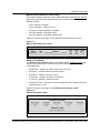
Figure 5-2 shows the "Shelf Configuration" dialog launched by clicking the
Shelf Add/Search operation link.
Figure 5-2
Shelf Configuration dialog
Software Release 3.00 StormTracker-Site Manager and Administration User Guide 08-01148-01-200
Using the Database Module 5-5
Procedure 5-1
Provisioning EtherLoop modems
Use this procedure to provision any EtherLoop modems installed on the
system. This procedure must be done to before using YesWare to provision
EtherLoop CO modems as switches.
Action
Step Action
1
Using a PC web browser, browse to the IP address configured for the ETH 0
interface, and login to the StormTracker-Site Manager software group.
2
In the Modex Daemon module, configure the Modex daemon interface
according to the system application as described in “Modex Daemon ETH 0
/ ETH 1 interface configuration” on page 5-3.
3
Use the Shelf Add/Search operation in the Database module to provision any
managed modem shelves in the system as described in “Provisioning
managed shelves” on page 5-4.
4
Select the Discover Modems operation from the Database module to launch
the "Discover EtherLoop Modems" dialog as shown in Figure 5-3.
Figure 5-3
Discover EtherLoop Modems dialog
—continued—
Software Release 3.00 StormTracker-Site Manager and Administration User Guide 08-01148-01-200
5-6 Using the Database Module
Procedure 5-1 (continued)
Provisioning EtherLoop modems
Step Action
5
Select the desired option (detect new modems and update modem
information, or only detect new modems).
6
Click the "AutoDetect Modems" button.
Figure 5-4 shows an example of the completed operation.
Figure 5-4
EtherLoop Modems detected
—continued—
Software Release 3.00 StormTracker-Site Manager and Administration User Guide 08-01148-01-200
Using the Database Module 5-7
Procedure 5-1 (continued)\
Provisioning EtherLoop modems
Step Action
7
Use the CO and CPE add/search operations to manually provision any
required site-specific modem parameters.
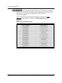
Figure 5-5 shows an example of the "CO Modem Configuration" dialog. This
dialog is launched by clicking either the edit link in the CO Modem View/Edit
operation dialog or the CO Modem Add/Search operation link.
Figure 5-5
CO Modem Configuration dialog
STOP
You have completed this task.
Software Release 3.00 StormTracker-Site Manager and Administration User Guide 08-01148-01-200
5-8 Using the Database Module
Procedure 5-2
Exporting and importing EtherLoop modem
databases
This procedure describes how to use the Export to File and Import from File
operations to export and import an EtherLoop modem database.
Using the Database / Export to File function
The Database / Export to File function exports provisioned database data from
the CO/CPE modem database to a file. You must export and download the data
to a file on a workstation to import it into the database of a Site Manager. The
downloaded file is a comma-separated-value file that can be edited using an
Excel or compatible spreadsheet.
Editing data in an exported modem database
Row data such as IP address, shelf, and slot can be modified, and rows (i.e.
modems) can be added, but do not change table names, column names, or
column positions. Save the modified file in comma-separated-value format if you
will be importing it back into a StormTracker-Site Manager database.
Using the Database / Import from File function
Imported data is merged into the existing database. To completely replace the
contents of the database with the imported data, first erase the database via the
'Clear DB' Database operation, then reselect 'Import from File'.
Only import a file that was exported using the 'Export to File operation. If you
edit the exported file, be sure to save it as a text file in comma-separated-value
(.csv) or tab-separated-value (.tsv or .txt) format.
—continued—
Software Release 3.00 StormTracker-Site Manager and Administration User Guide 08-01148-01-200
Using the Database Module 5-9
Procedure 5-2 (continued)
Exporting and importing EtherLoop modem databases
Action
Step Action
Exporting the modem database
1
Browse to the IP address of the BitStorm Server containing the desired
EtherLoop CO/CPE modem database.
2
Select the StormTracker-Site Manager software group and Database from
the StormTracker-Site Manager module menu.
3
Select the Export to file function, and click on the "Retrieve the exported
database" link.
Note: To view the exported data, left-click on the link. (If a dialog box appears
with the options 'Open...' and 'Save...', select 'Open' to view, or 'Save’ to
download).
4
To download the exported file, right-click on the "Retrieve the exported
database" and select the 'Save to target...' menu item. Save the file to a
desired location on your workstation or network.
Importing the modem database
5
Browse to the IP address of the BitStorm Server controlling the system.
6
Select the StormTracker-Site Manager software group and Database from
the StormTracker-Site Manager module menu.
7
Select the Import from File function, and enter or browse to the file containing
the exported database.
8
Select the "Import and Provision" or "Import Only" button, depending on your
requirements.
Import from File / Import and Provision vs. Import Only
Click 'Import and Provision' to automatically provision modems with the
imported IP address, shelf and slot. Click 'Import Only' to import CO/CPE
modem database without provisioning the modems on the Site Manager.
The ’Import Only’ option is useful if you need to make changes to the
database (such as changing/adding IP addresses) before provisioning the
modems into the system Site Manager database.
If the function is executed, the system displays "File has been imported
successfully."
STOP
You have completed this task.
Software Release 3.00 StormTracker-Site Manager and Administration User Guide 08-01148-01-200
5-10 Using the Database Module
Software Release 3.00 StormTracker-Site Manager and Administration User Guide 08-01148-01-200
6-1
Using EtherCraft
6-
This chapter describes the features and capabilities of the EtherCraft module.
EtherCraft is a diagnostics and performance monitoring tool for monitoring
EtherLoop modem status and performance. EtherCraft can examine all
modems or selected modems that have been provisioned using the Database
module. EtherCraft can only be used after the EtherLoop modem database has
been provisioned.
Chapter Contents
This chapter includes the following information.
Topic
See
EtherCraft OAM&P features
page 6-2
Modem management
page 6-4
Log Management
page 6-16
Privacy Management
page 6-18
CO modem port management
page 6-19
CPE modem port management
page 6-20
Software Release 3.00 StormTracker-Site Manager and Administration User Guide 08-01148-01-200
6-2 Using EtherCraft
EtherCraft OAM&P features
The Site Manager EtherCraft module supports the following EtherLoop
modem OAM&P features:
• modem monitoring and performance management
• communications privacy management
• modem activity log management
The following sections contain a brief overview of these features. The
remainder of this chapter details the operation and use of the functions
contained in these features.
EtherLoop modem monitoring and performance management
EtherCraft’s Modem Status operation provides the ability to perform a variety
of modem monitoring activities, including:
• Check modem speeds
• Display comprehensive tables showing modem performance including
modems speeds, training counts, retraining, Ethernet metrics, and HDLC
metrics
• View modem firmware version information
• Clear or get modem logs
• Display lists of currently active modems
• Reset modems
“Modem management” on page 6-4 describes the operation and use of the
Modem Status operation. Table 6-1 lists the sections in this chapter describing
each of the Modem Status operation dialogs.
Table 6-1
Modem Mgmt function descriptions
Modem Status function
See
Check Speeds
page 6-7
Modem Details
page 6-8
Client Addresses
page 6-12
Status
page 6-13
Version
page 6-14
Reset Modems
page 6-15
Software Release 3.00 StormTracker-Site Manager and Administration User Guide 08-01148-01-200
Using EtherCraft 6-3
View Logs
EtherCraft’s View Logs operation provides the ability to view, download or
delete the entries to the folowing EtherLoop logs:
• IPBOA ("legacy" name for current Modem Details logs)
• Client Address
• Status
• Version
Log files are stored/downloaded in a comma-separated value (*.csv) file
format. Upon retrieval, the log files are automatically converted into a
Microsoft Excel file that can be saved on the local workstation or network.
“Log Management” on page 6-16 describes the operation and use of the Log
Mgmt feature.
Privacy Mgmt
EtherCraft’s Privacy Mgmt operation provides the ability to secure
communications between EtherLoop modems using each individual
EtherLoop modem’s MAC filtering capability. EtherLoop MAC filtering
ensures that a particular client cannot see traffic destined for other clients.
EtherLoop MAC filters prevent or allow communications based on the MAC
addresses provisioned in a modem’s Filter table. If MAC addresses are
provisioned in Privacy Mgmt for a CPE/CE modem, traffic from all other
clients on the EtherLoop system are prevented from appearing at the CPE/CE
modem. In addition, only registered hosts connected to the CPE/CE modem
can use the connection.
“Privacy Management” on page 6-18 describes the operation and use of the
Privacy Mgmt feature.
Software Release 3.00 StormTracker-Site Manager and Administration User Guide 08-01148-01-200
6-4 Using EtherCraft
Modem management
The first step in using EtherCraft is to select the modem(s) to monitor.
EtherCraft provides the following modem selection capabilities:
•
•
•
•
Time delay entry, to specify the time delay to refresh data a specified
number of seconds.
Monitoring of all EtherLoop modems
Monitoring selected modems using choices from lists of Client and Server
modems
Specification of the delay time between modem queries
EtherLoop modem speeds and training counts
EtherCraft presents EtherLoop modem speedsusing tables that contain codes
representing 24 possible modem speed levels (0-23). Modem training counts
are calculated at each speed and the results of the training counts are shown
using a code (seeTable 6-3 on page 6-6). For example, if a modem is trained at
a speed of 2857 Kbps (Speed Code 17) and the speed is found to be acceptable,
a training Code of 10 is displayed to indicate the results of the training.
Note: With this release, only speeds 0-19 are available.
EtherCraft speeds tables
Table 6-2 on page 6-5 lists the modem speed codes and the estimated
throughput for the corresponding QAM16 and QPSK speed values.
Software Release 3.00 StormTracker-Site Manager and Administration User Guide 08-01148-01-200
Using EtherCraft 6-5
Table 6-2
Estimated throughput at different modem speeds
Modem Speed ksps
Code
Modulation
kbps
0
62.50
QPSK
125
1
89.29
QPSK
178
2
125.00 QPSK
250
3
62.50
250
4
178.57 QPSK
357
5
89.29
357
6
250.00 QPSK
500
7
125.00 16 QAM
500
8
357.14 QPSK
714
9
178.57 16 QAM
714
10
500.00 QPSK
1000
11
250.00 16 QAM
1000
12
714.29 QPSK
1428
13
357.14 16 QAM
1428
14
833.33 QPSK
1666
15
1000
2000
16
500.00 16 QAM
2000
17
714.29 16 QAM
2857
18
833.33 16 QAM
3333
19
1000
4000
16 QAM
16 QAM
QPSK
16 QAM
Modem training counts
Table 6-3 on page 6-6 lists the modem training counts and the meaning of each
code.
Software Release 3.00 StormTracker-Site Manager and Administration User Guide 08-01148-01-200
6-6 Using EtherCraft
Table 6-3
Check Speed training count interpretation
Code
Description
15
Modem has been trained, speed has been used and
the LQF is > or = 98%
11 thru14
Modem has been trained, speed has a high LQF but
has burned off at least once.
10
Modem has been trained, the speed has not been
used, or the modem has used the speed and the LQF
is between 85-98%
1 thru 9
Modem has been trained, but burned off at least once
because of LQF or SNR problems
0
Modem has not been trained, or once modem was
trained was burned off because of poor LQR or SNR
-1 thru -5
Modem has failed to this this many times. The
modem will not attempt to retrain a speed with a -5 or
-3 training count. Once per hour the modem will set
all untrained speeds to -4 to allow another training
attempt for that speed.
-6
Modem has been marked as untrainable because the
firmware determined the apparent distance between
modems was too long to support this speed
-7
Modem has been marked as unusable.
-10
Modem is currently being trained
NA
Modem was unavailable to determine its training
count at that particular speed
Software Release 3.00 StormTracker-Site Manager and Administration User Guide 08-01148-01-200
Using EtherCraft 6-7
Check Speeds
Use this operation to check the transmit speeds of selected client or server
modems. You can display the following values for training results based on
training at different speeds.
•
•
•
Type of modem—client or server modem.
Speeds—shown using codes to represent QAM16 and QPSK values
Mac address for the modem along with its training counts—training counts
are interpreted using codes to indicate the results of training at different
speeds
Access this function from the EtherCraft page by clicking the Check Speeds
button. Figure 6-1 shows the Check Speeds page.
Figure 6-1
EtherCraft Check Speeds page
Software Release 3.00 StormTracker-Site Manager and Administration User Guide 08-01148-01-200
6-8 Using EtherCraft
Modem Details
The Modem Details function of EtherCraft displays comprehensive modem
data. Figure 6-2 shows an example of the EtherCraft Modem Details page.
Note: The Modem Details function was formerly called IP BOA
The following sections present a detailed look at the information available on
the Modem Details page.
Figure 6-2
EtherCraft / Modem Details
Software Release 3.00 StormTracker-Site Manager and Administration User Guide 08-01148-01-200
Using EtherCraft 6-9
Modem identification and version table
The modem identification and version table (first table on the Modem Details
page) shows the following identification and version information for each
modem selected:
•
•
•
•
•
MAC address of modem
Type of modem—client or server
Firmware version installed on modem
Revision number of modem board
Revision number of modem analog board
Figure 6-3 shows an example of the identification and version section.
Figure 6-3
Modem identification and version
Ethernet Port Metrics
The Ethernet Port Metrics table (second table on the Modem Details page)
includes a measurement of the following on the Ethernet side of modem
communications:
• RX Frames - number of frames (or packets) received
• RX Bytes - amount of data received in bytes
• RX Errors - number of receive errors
• TX Frames - number of frames transmitted
• TX Errors - number of transmit errors
• Modem Up Time - amount of time the modem has been running since the
last power-up or reset.
Figure 6-3 shows an example of the Ethernet Port Metrics table:
Figure 6-4
Ethernet Port Metrics table
Software Release 3.00 StormTracker-Site Manager and Administration User Guide 08-01148-01-200
6-10 Using EtherCraft
Speeds tables, modem speeds and training counts
Speeds tables follow the Ethernet Port Metrics table, and present values for
these transmit and receive parameters:
• Server _Tcount—Transmit speed of CO/SE modems
• Client_Tcount—Transmit speed of CPE/CE modems
• Retrain_RX—Receive retrain count; value is ‘-’ if run on CPE/CE modem
• Retrain_TX—Transmit retrain count; value is ‘-’ if run on CPE/CE modem
•
•
•
•
Tx_Atten - Attenuation in dB from the maximum transmit output power on
the CO/SE modem
Client_TxAtten -Attenuation in dB from the maximum transmit output
power on the CPE/CE modem
Rx_Gain - Gain in dB the modem had to apply to the receive channel in
order to hear the far end modem
Preamp - ain in one of four coarse settings (3, 11, 19, 27dB) applied to the
receive channel to enable it to hear the far end modem
A speeds table is displayed for each modem port. For example, EtherCraft
displays 12 speeds tables for ELMo 120 modems, numbered Port 0-Port 11.
Figure 6-5 shows an example of a speed table for Port 6 of an ELMo 120
modem.
Figure 6-5
Speeds table example
Software Release 3.00 StormTracker-Site Manager and Administration User Guide 08-01148-01-200
Using EtherCraft 6-11
HDLC Port Metrics
An HDLC Metrics table is associated with each speeds table displayed for the
modem port. HDLC Metrics include a measurement on the side of the phone
link between modems. The HDLC Metrics table displays the following:
• RX Frames—number of frames (or packets) received
• RX Bytes—amount of data received in bytes
• RX Errors—number of receive errors
• RX Blocks - number of blocks received
• TX Frames—the number of frames transmitted
• Retries - number of re-transmission attempts
• Data Frames - number of data frames transmitted
• Discard Frames - number of HDLC discard frames
• Free Buffers - available storage for data to compensate for differences in
transmission speeds or timing
• Local LQF - local line quality factor on a scale of 100
•
•
Remote LQF - remote line quality factor on a scale of 100
Apparent Distance - estimate of distance between server (CO/SE) and
client (CPE/CE) modem to the nearest 1000 feet (displayed in Kft)
Figure 6-6 shows an example of an HDLC Metrics table.
Figure 6-6
HDLC Port Metrics table example
Software Release 3.00 StormTracker-Site Manager and Administration User Guide 08-01148-01-200
6-12 Using EtherCraft
Client Addresses
Use this function to display the MAC addresses of clients that correspond to
selected server modems. The addresses are displayed in columns by type of
modem. If no client modem is assigned, the system displays
"No_Client_Modem."
Access this function from the EtherCraft page by clicking the Client
Addresses button. Figure 6-7 shows the Client Addresses page.
Figure 6-7
EtherCraft Client Addresses page
Software Release 3.00 StormTracker-Site Manager and Administration User Guide 08-01148-01-200
Using EtherCraft 6-13
Status
Use this function to test whether modems are responding or are unavailable.
The modems are listed by MAC address. The status is either "Ok" in the
Responds field or an "X" in the Unavailable field.
Access this function from the EtherCraft page by clicking the Status button.
Figure 6-8 shows an example of the Status page.
Figure 6-8
EtherCraft Status page
Software Release 3.00 StormTracker-Site Manager and Administration User Guide 08-01148-01-200
6-14 Using EtherCraft
Version
Use this function to retrieve firmware code page (memory location) and
FPGA page information, current firmware version, and the modem printed
circuit board (PCB) revision. The modems are listed by MAC address.
Access this function from the EtherCraft page by clicking the Status button.
Figure 6-8 shows an example of the Status page.
Figure 6-9
EtherCraft Version page
Purpose of the Version function
The EtherCraft Version screen is useful for modem support, testing, and
administration., and provides a useful way track performance and troubleshoot
modems as the hardware and firmware is enhanced.
The Version screen indicates the code page (memory location) that is active for
the modem code page and FPGA (field programmable gate array) code page.
FPGAs are programmable logic chips with a high density of gates that the
modem uses in signal processing. In the modems, the value for the active code
page is either 0 or 1. The code page swaps with each upgrade that is
downloaded to the modem.
Version page field values
The version information includes the following values for each modem:
• Active Code Page—values are either 0 or 1 for the active memory location
for the modem code
• Active FPGA Page—values are either 0 or 1 for the active memory
location for the FPGA code
• Firmware Revision—current firmware version being used by the modem
• Board Revision—modem printed circuit board revision for the selected
modem
Software Release 3.00 StormTracker-Site Manager and Administration User Guide 08-01148-01-200
Using EtherCraft 6-15
Reset Modems
Use this function to reset selected modems. Resetting the modems clears
current activity from the modem and restarts modem operation.
CAUTION - Reset Modems causes loss of service
This procedure will cause temporary loss of service. Do only at low-traffic periods
Access this function from the EtherCraft page by clicking the Reset Modems
button. On the Clear Logs page, click the logs you want to retrieve or click
Return to start to clear your selections on the Get Logs page without
retrieving the log files.
Figure 6-11 shows an example of the Reset Modems page.
Figure 6-10
EtherCraft Reset Modems page
Software Release 3.00 StormTracker-Site Manager and Administration User Guide 08-01148-01-200
6-16 Using EtherCraft
Log Management
Use this feature to download or delete selected EtherCraft logs. The Log Mgmt
feature can retrieve or delete entries to the following logs:
• IPBOA ("legacy" name for current Modem Details function)
• Client Address
• Status
• Version
Log files are stored in a comma-separated value (*.csv) file format. Upon
retrieval, the log files are automatically converted into a Microsoft Excel file
that can be saved on the local workstation or network.
Using the Get Logs function
Access this function from the EtherCraft page by clicking the Get Logs
button. On the log retrieval page, click the logs you want to retrieve or click
Return to start to clear your selections on the Get Logs page without
retrieving the log files.
Figure 6-11 shows an example of the Get Logs page.
Figure 6-11
EtherCraft Get Logs page
Software Release 3.00 StormTracker-Site Manager and Administration User Guide 08-01148-01-200
Using EtherCraft 6-17
Using the Clear Logs function
Use this function to clear selected EtherCraft logs.
CAUTION - Removing EtherCraft logs is permanent
When clearing EtherCraft logs no backup is made for the logs. By clearing the logs
you remove entries permanently from the EtherCraft log files.
Access this function from the EtherCraft page by clicking the Clear Logs
button. On the Clear Logs page, click the logs you want to remove or click
Return to start to clear your selections on the Clear logs screen without
clearing the log files.
Figure 6-12 shows an example of the Clear Logs page.
Figure 6-12
EtherCraft Clear Logs page
Software Release 3.00 StormTracker-Site Manager and Administration User Guide 08-01148-01-200
6-18 Using EtherCraft
Privacy Management
Access this feature by clicking the EtherCraft Privacy Mgmt operation. This
feature provides the ability to manage each individual EtherLoop modem’s
MAC filtering capability. An EtherLoop modem "privacy filter" is a MAC
address entry stored in a modem that allows Ethernet traffic to and from only
the gateway whose address matches the entry in the MAC filter table.
Figure 6-13 shows an example of the EtherCraft Privacy Mgmt page.
Figure 6-13
EtherCraft Privacy Mgmt page
Using the Privacy Mgmt feature
Separate MAC filter tables exist for CO and CPE modems. If no MAC
addresses appear in the MAC Filter table for a particular modem, it will pass
all Ethernet traffic. If any MAC addresses appear in the MAC Filter table for
a particular modem, the modem will only accept Ethernet packets from those
addresses.
To add or remove a privacy filter, select the modem(s) to modify and do the
following:
• Click Display Filter Tables to see the MAC address entries for the
modems listed. The table appears at the bottom of the screen.
• Enter a MAC address in the MAC Filter Address field.
• Click the Add or Remove button to add or remove it from the Filter Table.
It is possible to store up to eight addresses per modem, allowing multiple
gateways to be used. The Reset Filter Tables button returns the filter table to
default settings.
Software Release 3.00 StormTracker-Site Manager and Administration User Guide 08-01148-01-200
Using EtherCraft 6-19
CO modem port management
Access this feature by clicking the EtherCraft CO Port Mgmt operation. This
feature provides the ability to enable or disable each individual port on the
multiport CO modems.
Figure 6-14 shows an example of the EtherCraft CO Port Mgmt page.
Figure 6-14
EtherCraft CO Port Mgmt page
Software Release 3.00 StormTracker-Site Manager and Administration User Guide 08-01148-01-200
6-20 Using EtherCraft
CPE modem port management
Access this feature by clicking the EtherCraft CPE Port Mgmt operation. This
feature provides the ability to enable or disable each individual CPE modem.
Figure 6-15 shows an example of the EtherCraft CPE Port Mgmt page.
Figure 6-15
EtherCraft CPE Port Mgmt page
Software Release 3.00 StormTracker-Site Manager and Administration User Guide 08-01148-01-200
7-1
Using the Downloader module
7-
This chapter describes how to use the Downloader module.
Chapter Contents
This chapter includes the following information.
Topic
See
Downloader purpose and function
page 7-2
Using Downloader
page 7-2
Downloader status and logs
page 7-2
Chapter task list
This chapter includes the following tasks.
Procedure
Task
See
7-1
Upgrading EtherLoop modem firmware
page 7-3
7-2
Upgrading from Generation 1 to Generation 2 modem page 7-6
firmware
Software Release 3.00 StormTracker-Site Manager and Administration User Guide 08-01148-01-200
7-2 Using the Downloader module
Downloader purpose and function
The Downloader module is used to download firmware and FPGA (field
programmable gate array) code for any number of Elastic system modems.
These modems are selected by querying the modem database. The
Downloader module examines the file header when told to download a certain
file to the modem to verify the authenticity, type, and reliability of the file.
Downloader monitors and displays the progress of a download and alerts the
operator if any problems occurred during the download.
Using Downloader
EtherLoop modem firmware upgrades can use either FPGA (field
programmable gate array) code or modem firmware. The overall process of
upgrading EtherLoop modem firmware consists of uploading the new
firmware to the YWS from a diskette or a location on a reachable network, and
then downloading the firmware to the modems managed by the system YWS.
Procedure 7-1 on page 7-3 describes the steps required to upgrade the
firmware and/or FPGA code on a YWS.
Downloader options
When using Downloader, you will select the following options:
•
Database. This is the database where modem MAC addresses are stored.
Currently, "System Inventory" is the only selection.
•
Modem(s) to which you will be downloading or uploading. The
available MAC addresses for the System Inventory Database include:
— CO Modems: All of the CO/SE modems available in the currently
selected database.
— CPE Modems: All of the CPE/CE modems available in the currently
selected database.
CAUTION - Avoid firmware version conflicts
CO/SE and CPE/CE modems can be selected individually or in groups for
the firmware upgrade. To avoid firmware version conflicts, always upgrade
modem pairs (CO/CPE) simultaneously. This can be done automatically by
selecting the option to "Auto-select all modems in the same Server/Client
group" in the Downloader Main Menu.
•
•
Firmware/FPGA. This is the file containing the firmware for each of
these firmware types to download to the selected modems.
Shelf Devices. Select any shelf devices provisioned.
Downloader status and logs
Downloader’s View Last Status and View Logs functions in allow you to view
the status of the last download or upload, or view the history log of all
downloads performed.
Software Release 3.00 StormTracker-Site Manager and Administration User Guide 08-01148-01-200
Using the Downloader module 7-3
Procedure 7-1
Upgrading EtherLoop modem firmware
Use this procedure to upgrade the EtherLoop modem firmware using the
Downloader module.
Requirements
To do this procedure, you need the following:
•
A file containing the new modem firmware and/or FPGA code on a 3.5inch diskette, local workstation or reachable network location.
Action
Step
Action
1
From the YesWare Main Menu, choose Downloader.
The Downloader Main Menu appears as shown in Figure 7-1.
Figure 7-1
Downloader Main Menu
—continued—
Software Release 3.00 StormTracker-Site Manager and Administration User Guide 08-01148-01-200
7-4 Using the Downloader module
Procedure 7-1 (continued)
Upgrading EtherLoop modem firmware
Step
Action
2
Click the "Upload New Files" button.
The Downloader / Modem Firmware Uploader appears as shown in
Figure 7-2.
Figure 7-2
Downloader / Modem Firmware Uploader
3
Browse to the location of the file containing the new load for the modem
firmware/FPGA code.
4
Click the "Upload Files" button. The system installs the new load into the
YWS "downloader" directory.
5
When all files have been uploaded, click the "Return To Main Menu" button.
6
In the Downloader Main Menu, use the "Files To Download" pull-down menus
and select the newly-uploaded Firmware/FPGA load(s).
7
In the "Modems To Update" section of the page, select the modem database
and modems to receive the upgraded firmware/FPGA code.
8
Click the "Begin Downloading" button to begin upgrading the modems and
modem database.
—continued—
Software Release 3.00 StormTracker-Site Manager and Administration User Guide 08-01148-01-200
Using the Downloader module 7-5
Procedure 7-1 (continued)
Upgrading EtherLoop modem firmware
Step
Action
When the download is complete, the system displays a Download Status
page with the following information:
•
status of download (complete)
•
start and end times of download
•
file name of firmware code used in download
•
number of modems that receiving download
•
percent of file transfers completed (%)
•
percent of modem programming completed (%)
•
number of failed downloads
•
number of modem resets completed
In addition, a second table on the Download Status page displays the
following results for any failed downloads:
•
modem MAC address(es)
•
modem type (CO or CPE)
•
download type (Firmware/FPGA Code)
•
reason for download failure
STOP
You have completed this task.
Software Release 3.00 StormTracker-Site Manager and Administration User Guide 08-01148-01-200
7-6 Using the Downloader module
Procedure 7-2
Upgrading from Generation 1 to Generation 2 modem
firmware
Use this procedure to upgrade ELMo 8 and Elite EtherLoop modem firmware
from Generation 1 to Generation 2.
Requirements
To do this procedure, you need the following:
• A file containing the Generation 2 modem firmware on a 3.5-inch diskette,
local workstation or reachable network location. Generation 2 firmware fil
names all begin with "02_". The firmware required for this procedure
includes two files with the following file name format:
— 02_xx_xx_boot.bin
— 02_xx_xx_e1.bin
EtherLoop modem firmware files named 02_xx_xx_mp.bin are multiplexer
firmware files and are upgraded using the standard firmware upgrade
procedure described in Procedure 7-1 on page 7-3. There is no Gen. 1
multiplexer firmware.
Special procedure requirements
The following should be noted about this procedure:
•
•
•
Gen-1 to Gen-2 firmware upgrades can take up to 15 minutes per modem
pair. Do not stop the procedure until the "complete" window appears as
described in this procedure.
The web browser of the PC performing the upgrade must be left with the
Downloader / Gen-1 to Gen-2 Upgrade Menu as the active browser
window. No other web browser windows should bel launched during the
upgrade procedure.
Always ensure the "Auto-select both modems of a Server/Client pair" box
is checked and upgrade modem firmware in the assigned CO/CPE pairs.
—continued—
Software Release 3.00 StormTracker-Site Manager and Administration User Guide 08-01148-01-200
Using the Downloader module 7-7
Procedure 7-2 (continued)
Upgrading from Generation 1 to Generation 2 modem firmware
Action
Step
Action
1
From the Downloader main menu, click the "Upload New Files" button to
launch the Modem Firmware Uploader dialog as shown in Figure 7-2.
Figure 7-3
Downloader / Modem Firmware Uploader
2
Browse to the location of the file containing the new load for the modem
firmware files.
3
Click the "Upload Files" button. The system installs the new load into the
YWS "downloader" directory.
4
When all files have been uploaded, click the "Return To Main Menu" button.
—continued—
Software Release 3.00 StormTracker-Site Manager and Administration User Guide 08-01148-01-200
7-8 Using the Downloader module
Procedure 7-2 (continued)
Upgrading from Generation 1 to Generation 2 modem firmware
Step
Action
5
In the Downloader Main Menu, select "Gen-1 to Gen-2" upgrade to launch the
Gen-1 to Gen-2 Upgrade Menu.See Figure 7-4.
Figure 7-4
Gen-1 to Gen-2 Upgrade Menu
6
Use the "Target Gen-2 Code File" pull-down menu and select the newlyuploaded Gen-2 firmware load. The remaining Files To Download
("Transition Gen-1 Code File," "Transition FPGA File," and "Transition
Bootcode File") firmware loads are autofilled by the system.
7
In the "Gen-1 Modems To Convert" section of the page, select the modem
database and modems to receive the upgraded firmware code.
8
Click the "Begin Gen-2 Upgrade" button to begin upgrading the modems and
modem database.
—continued—
Software Release 3.00 StormTracker-Site Manager and Administration User Guide 08-01148-01-200
Using the Downloader module 7-9
Procedure 7-2 (continued)
Upgrading from Generation 1 to Generation 2 modem firmware
Step
Action
When the Gen-2 upgrade is complete, the system displays a Downloader
Status page as shown in Figure 7-5.
Figure 7-5
Firmware Gen-2 upgrade complete
STOP
You have completed this task.
Software Release 3.00 StormTracker-Site Manager and Administration User Guide 08-01148-01-200
7-10 Using the Downloader module
Software Release 3.00 StormTracker-Site Manager and Administration User Guide 08-01148-01-200
Elastic Networks
StormTracker-Site Manager
and Administration
User Guide
Software Release 3.00
Publication Number: 08-01148-01-200
Document Revision 2.00
© 2001 Elastic Networks
All rights reserved
The information contained in this document is subject to
change without notice. Elastic Networks reserves the right
to make changes to equipment design or program
components, as progress in engineering, manufacturing
methods, or other circumstances may warrant.
EtherLoop is a trademark of Elastic Networks.
Publication Date: March 2001
Printed in the United States of America