1
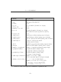
8.3. REGULATOR SELECTION
Device
Voltage
GSM Module
3.8V
Microprocessor
5.0V
LEDs
5.0V
LCD display
5.0V
LM35 Temp sensor
5.0V
TOTAL POWER
Ave Current
0.2% × 850mA
12mA b
1mA c
3mA max
130µA
a
Ave Power
1.7mW
60mW
5mW
15mW d
0.65mW
85mW
Table 8.1: Power requirements of the uplink module.
All values measured unless otherwise stated.
a
GSM module is usually idle. Assuming power-up time of two and a half minutes per
day.
b
PIC 18F4620 5.0V operation at 8MHz HS oscillator enabled.
Red High Efficiency (1mA) LEDs driven by 5.0V logic outputs through a suitable
resistor with average 50% duty cycle.
d
Worst-case scenario from device datasheet.
c
8.3
Regulator Selection
In order to extract the maximum useful life from the battery and prevent
overheating in the sealed enclosure, the converters should be highly efficient.
Linear regulators, when dropping from 12V to 3.8V, have a conversion efficiency
of less than 32%. Matters do not improve much at 5V with less than 42%
of consumed energy being useful. Linear regulators are thus immediately
dismissed due to their inefficiency in this application.
Switched-mode converters exhibit much higher efficiencies — over 95%
is possible with commercial, off-the-shelf buck converters1 . The primary
drawback of these circuits is the switching noise which is produced on the
supply rails. A further concern is the typical operating frequency of 100kHz
to 200kHz. This is precisely the operating frequency of the RFID reader
and will inevitably result in interference. Many devices were considered with
mixed results. Consult Appendix D for a full list of all devices considered.
Oulined below are details of two evaluated buck switching converters.
1
e.g. Maxim’s range of switched mode DC-DC buck converters at www.maxim-ic.com.
90