1
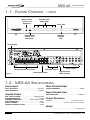
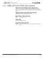
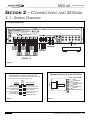
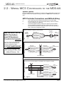
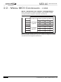
MDS-6A
Integrated Multi-ZZone Controller
INSTALLATION MANUAL
AND
USER’S GUIDE
TM
MDS-6A
MDS-6A
TABLE
OF
INSTALLATION MANUAL
CONTENTS
SECTION 1
Introduction
1.1 Feature Overview . . . . . . . . . . . . . . . . . . . . . . . . . . . .5
1.2 MDS-6A Specifications. . . . . . . . . . . . . . . . . . . . . . . . .6
1.3 MDS-6A Front Panel Adjustments . . . . . . . . . . . . . . . .7
SECTION 2
Connections and Settings
2.1 System Overview . . . . . . . . . . . . . . . . . . . . . . . . . . . .8
2.2 Wiring MCS Controllers to the MDS-6A . . . . . . . . . . . .9
2.3 Source and IR Connections . . . . . . . . . . . . . . . . . . . .11
SECTION 3
Troubleshooting
3.1 MCS Controller Operation . . . . . . . . . . . . . . . . . . . . .12
3.2 Infrared . . . . . . . . . . . . . . . . . . . . . . . . . . . . . . . . . .13
3.3 Audio Source Control . . . . . . . . . . . . . . . . . . . . . . . .13
LIMITED WARRANTY . . . . . . . . . . . . . . . . . . . . . . .Back Page
Page 2
© Channel Plus, Inc. 2004 • All rights reserved. 4/04
MDS-6A
INSTALLATION MANUAL
IMPORTANT SAFETY INFORMATION
Read Information—All the safety and operating information should be read before the appliance is operated.
Follow Information—All operating and use information should be followed.
Retain Information—The safety and operating information should be retained for future reference.
Heed Warnings—All warnings on the appliance and in the operating instructions should be heeded.
Wall Mounting—Mounting of this appliance should be done only by an authorized installer.
Ventilation—The appliances should be situated so that their location or position does not interfere with their proper ventilation. These
appliances should never be placed near or over a radiator or heat register. These appliances should not be placed in a built-in installation such
as a bookcase or cabinet that may impede the flow of air through the ventilation openings.
Non-Use Periods—Appliances that are left unattended and unused for long periods of time should be de-energized.
Power Sources—The appliances should be connected to a power supply only of the type described in the operating instructions or as
marked on each appliance. If you are not sure of the type of power supply to your home, consult your authorized Channel Plus dealer or local
power company.
Grounding or Polarization—These audio products must be connected to a grounding-type alternating-current circuit on a dedicated circuit breaker. This is a safety feature. The green safety wire from the A.C. circuit must be connected.
Water and Moisture—To reduce the risk of electric shock or fire, these appliances should not be used near water––for example, near a
bathtub, washbowl, kitchen sink, laundry tub, in a wet basement, or near a swimming pool.
© Channel Plus, Inc 2004 • All rights reserved. 4/04
Page 3
MDS-6A
INSTALLATION MANUAL
Power Cord Protection—A.C.Power supply circuits should be routed by a certified electrician only, in accordance with the NEC standards.
Telephones—Avoid using a telephone (other than a cordless type) during an electrical storm. There may be a remote risk of electrical shock
from lightning. Do not use a telephone to report a gas leak if the leak is in the vicinity of the Channel Plus electronic equipment because of risk of
fire or explosion.
Cleaning—Turn off the circuit breaker to this audio product before cleaning. Do not use liquid or aerosol cleaners. Use a damp cloth for cleaning.
Power Lines—An outdoor antenna should be located away from power lines. When installing an outside antenna system, extreme care
should be taken to avoid touching power lines or circuits, as contact with them may be fatal.
Outdoor Antenna Grounding—If an outside antenna or cable system is connected to these audio products, be sure the antenna
or cable system is grounded so as to provide some protection against voltage surges and built-up static charges. Section 810 of the U.S. National
Electrical Code, and Section 54 of the Canadian Electrical Code, provide information with
respect to proper grounding of the mast and supporting structure, grounding of the lead-in wire Grounding
to an antenna discharge unit, size of grounding conductors, location of antenna-discharge unit, Diagram
connection to grounding electrodes, and requirements for the grounding electrode. See the
ANTENNA
grounding diagram (right).
LEAD-IN WIRE
Overloading—Do not overload wall outlets and extension cords, as this could result in
GROUND
CLAMPS
fire or electric shock.
ANTENNA LEAD-IN WIRE
(CEC SECTION 54-200)
(NEC SECTION 810-20)
Object and Liquid Entry—Never insert objects of any kind through the openings
ELECTRIC
SERVICE
EQUIPMENT
of these appliances, as they may touch dangerous voltage points or short-out parts that could
result in a fire or electric shock. Care should be taken so that objects do not fall and liquids are
not spilled into the appliance through openings in the enclosure.
Servicing—Do not attempt to service these appliances yourself, as opening or removing
GROUNDING CONDUCTORS
(CEC SECTION 54-200)
(NEC SECTION 810-21)
GROUND CLAMPS
NEC - NATIONAL ELECTRICAL CODE
CEC - CANADIAN ELECTRICAL CODE
POWER SERVICE GROUNDING
ELECTRODE SYSTEM
(CEC SECTION 10-700)
(NEC ARTICLE 250, PART H)
covers may expose you to dangerous voltage or other hazards. Refer all servicing to qualified
service personnel.
Damage Requiring Service—These appliances should be serviced by qualified service personnel when:
•
•
•
•
•
A power supply connection or a plug has been damaged or
If liquid has been spilled into the appliance or objects have fallen into the appliance or
The appliance has been exposed to water or moisture or
The appliance does not appear to operate normally or exhibits a marked change in performance or
The appliance has been dropped or the enclosure damaged.
Replacement Parts—When replacement parts are required, be sure the service technician has used replacement parts specified by the
manufacturer or that have the same characteristics as the original part. Unauthorized substitutions may result in fire, electric shock, or other hazards.
Safety Check—Upon completion of any service or repairs to this audio product, ask the service technician to perform safety checks to
determine that the audio product is in proper operating condition.
Lightning—For added protection for these audio products during an electrical storm, or when they are left unattended and unused for long
periods of time, turn off the circuit breaker, and disconnect the antenna or cable system. This will prevent damage to the audio products due to
lightning and power-line surges.
FEDERAL COMMUNICATIONS COMMISSION (FCC) NOTICE:
This device complies with Part 15 of the FCC Rules. Operation is subject to the following conditions: (1) This
device may not cause harmful interference and (2) this device must accept any interference received, including
interference that may cause undesired operation.
Page 4
© Channel Plus, Inc. 2004 • All rights reserved. 4/04
MDS-6A
INSTALLATION MANUAL
SECTION 1 - INTRODUCTION
1.1 - FEATURE OVERVIEW
6 Sources / 6 Zones
The MDS-6A enables you to independently listen to and control up to six different audio sources (i.e. Tuner, CD, Tape Deck - and the audio signals from your
VCR, DVD, and Satellite Receiver) in six distinct listening areas or “zones”.
12 Channel x 40 WPC Power Amplifier
The MDS-6A features 12 channels of amplification capable of delivering 40
watts per channel into 8 ohms. The MDS-6A provides more than enough clean,
dynamic power to drive a house full of speakers all day long!
Compatible with MCS Zone Controllers and IR Receivers
The MDS-6A’s zones can be controlled using MCS-1A Zone Controllers,
MCS-2A Programmable Zone Controllers, and/or IR Receivers. Add multiple
MCS Controllers and/or IR Receivers for maximum flexibility.
User Feedback to All System Controllers
Unlike other basic multi-zone systems, the MDS-6A receives IR data and transmits feedback to MCS Controllers. These features inform the user of which
Source is currently selected, Zone ON/OFF Status, Mute, Do-Not-Disturb,
Whole-House Music Status, and more!
MCS Controller RJ-45 Jacks and Removable Speaker
Terminals for Easy Connectivity
In addition to the six plug 'n play RJ45 jacks for MCS Controllers and IR
Receivers, the MDS-6A features installer-friendly removable speaker terminals
which accept up to 14 AWG wire.
6 Source-Specific IR Output Ports Plus 1”ALL” Port
Six source-specific IR output ports enable multiple ‘same make/model’ components to be used without conflict or interference. An IR ALL port is also provided.
© Channel Plus, Inc 2004 • All rights reserved. 4/04
Page 5
MDS-6A
1.1 - FEATURE OVERVIEW -
INSTALLATION MANUAL
CONT.
Zone ON / OFF
Status LEDs
Music-on-Hold
Volume Level
Adjustment
Power LED
MDS-6A
TM
Page/Doorbell
Volume Level
Adjustment
IR Activity
Indicator
LED
Power Switch
Modular Speaker Connectors
Figure 1
Source Inputs
IR Emitter Outputs
Page/Doorbell/
Music on Hold
Zone Keypad Inputs
1.2 - MDS-6A SPECIFICATIONS
Source Inputs
Music On Hold Output
INPUT SENSITIVITY......................................................0-2V RMS
INPUT IMPEDANCE.........................................................47KOhm
OUTPUT IMPEDANCE.......................................................1KOhm
Amplifier Output
MAX. OUTPUT POWER.......................................40W @ 8 Ohms
SPEAKER IMPEDANCE....................................................8 Ohms
FREQUENCY RESPONSE........................20Hz to 20kHz, +/-1dB
THD+NOISE(@1KHz)..........................................................0.02%
SIGNAL-TO-NOISE..............................................................>95dB
CROSSTALK (ZONE TO ZONE).........................................>70dB
Page & Doorbell Input
INPUT IMPEDANCE.......................................................47KOhms
Chassis Dimensions
L x D x H.....................................................17 in. X12.5 in. X 4 in
.................................................43.18 cm. X31.75 cm. X 10.16 cm
Weight
............................................................................... 21 Lbs/9.53 Kg
Page 6
© Channel Plus, Inc. 2004 • All rights reserved. 4/04
MDS-6A
INSTALLATION MANUAL
1.3 - MDS-6A FRONT PANEL ADJUSTMENTS
Music-On-Hold Output Gain Adjustment
As shown on page 6, this potentiometer adjusts the gain of the Music-On-Hold signal
(Source #1) going to the Music-On-Hold input of a phone system or other communication
device.
Page/Doorbell Input Gain Adjustment
Adjusts the input level of the Page and Doorbell signal.
Zone Status LED Indicators
SOLID
Indicates the zone is on.
Power LED
Indicates the MDS-6A is powered up.
IR Activity Indicator LED
WINKING
© Channel Plus, Inc 2004 • All rights reserved. 4/04
Indicates that IR data is being received from a keypad or IR Receiver in a
zone.
Page 7
MDS-6A
SECTION 2 - CONNECTIONS
AND
2.1- SYSTEM OVERVIEW
INSTALLATION MANUAL
SETTINGS
SYSTEM OVERVIEW
WARNING
REPLACE FUSE WITH SAME
TYPE AND RATING ONLY
POWER
INTERT E K
T4AL TYPE FUSE
CM
C
US
L I ST E D
9700721
MODEL: MDS-6A
RISK OF ELECTRIC SHOCK
MUSIC DISTRIBUTION SYSTEM
DO NOT OPEN
WARNING: DO NOT REMOVE COVER.
AVIS
NO USER SERVICEABLE PARTS INSIDE.
REFER SERVICE TO CHANNEL PLUS
RISQUE DE CHOC ELECTRIQUE
SERVICE TECHNICIAN.
NE PAS OUVRIR
HOME SYSTEMS WITH AUDIO AND/OR VIDEO CONTROL CAPABILITIES.
ETL LISTED PRODUCT CONFORMS TO UL STD 6500 2ND EDITION
CERTIFIED TO CAN/CSA E60065-00
120VAC
60 Hz
440 W
FUSE
IR
EMITTERS
Sources x 6
MCS
KEYPADS
In-Wall & In-Ceiling Speakers
ZONES 1-6
Figure 2
MDS-6A/MCS Controller RJ45 PIN-OUT
Standard Channel Plus RJ-45 Pin-Out
The MDS-6A RJ-45 keypad jacks and all MCS Controller
RJ-45 jacks have the exact same pin-out.
Figure 3
Page 8
MCS Controller
Blue (N/C)
White/Blue (IR)
Orange (Clone Data)
White/Orange (RS485+)
Green (RS485-)
White/Green (+12VDC)
Brown (Ground)
White/Brown (N/C)
FRONT
MDS-6A
(N/C)Blue
(IR) White/Blue
(Clone Data) Orange
(RS485+) White/Orange
(RS485-)Green
(+12VDC) White/Green
(Ground)Brown
(N/C)White/Brown
RJ45
Jack
Pin #
1
2
3
4
5
6
7
8
PIN # COLOR CODE
1
2
3
4
5
6
7
8
TAB
BLUE
WHITE/BLUE
ORANGE
WHITE/ORANGE
GREEN
WHITE/GREEN
BROWN
WHITE/BROWN
CABLE
Figure 4
© Channel Plus, Inc. 2004 • All rights reserved. 4/04
MDS-6A
INSTALLATION MANUAL
2.2 - WIRING MCS CONTROLLERS
TO THE
MDS-6A
System Specs
Each of the MDS-6A’s Zone Controller RJ-45 Jacks provides 12VDC/300mA. These Zone
Keypad connections are capable of driving a maximum of TWO MCS Controllers per
zone.
MCS Controller Connections and MDS-6A Wiring
1.
2.
CAT-5 should be used for all MCS Controller wire runs (max 500ft).
MCS Controller wire runs can be terminated directly to RJ45 connectors
and then plugged into the MDS-6A.
Use RJ45-to-Pigtails Interface Cables and a point-to-point punchdown
block to facilitate the termination of MCS Controller wire runs. Use of a
punchdown block eliminates crimping and pinout errors while providing a
neat, on-wall wire management solution.
3.
MCS Controller to MDS-6A Connections
IMPORTANT NOTE
Each ZONE KEYPAD INPUT RJ45 jack
on the MDS-6A provides 12VDC/300mA.
You may choose to load each of the
MDS-6A’s ZONE KEYPAD INPUTS
with any combination of MCS
Controllers and/or IR Receivers as long
as the TOTAL CURRENT CONSUMPTION DOES NOT EXCEED 300mA.
MCS Controller (w/ IRTUBE) = 125mA
Additional IR Receivers = 10mA
A.
RJ45
Pigtail
MCS
Controller
CAT-5
RJ45
Pigtail
MCS Controller to MDS-6A Connections w/ Punchdown Block
ZONE KEYPAD INPUTS
MCS Controllers
and IR Receivers
Butt Splice
or
Equivalent
Blue (N/C)
White/Blue (IR)
Orange (Clone Data)
White/Orange(RS485+)
Green(RS485-)
White/Green (+12V)
Brown (GND)
White/Brown (N/C)
ZONE
KEYPAD
INPUTS
Blue (N/C)
White/Blue (IR)
Orange (Clone Data)
White/Orange (RS485+)
Green (RS485-)
White/Green (+12V)
Brown (GND)
White/Brown (N/C)
Blue (N/C)
MCS
White/Blue(IR)
CONTROLLER
Orange (Clone Data)
White/Orange (RS485+)
Green(RS485-)
White/Green(+12V)
Brown (GND)
White/Brown (N/C)
Punchdown Block
B.
CONNECTING TWO MCS CONTROLLERS IN ONE ZONE
ZONE KEYPAD INPUTS
Connect the IR, Ground, RS485+, and RS485- wires together in parallel
Punchdown Block
C.
© Channel Plus, Inc 2004 • All rights reserved. 4/04
Figure 6
White/Blue (IR)
Orange (Clone Data)
White/Orange (RS485+)
Green (RS485-)
White/Green(+12V)
Brown (GND)
MCS
Controller
White/Blue(IR)
Orange (Clone Data)
White/Orange (RS485+)
Green (RS485-)
White/Green (+12V)
Brown (GND)
MCS
Controller
Page 9
MDS-6A
2.2 - WIRING MCS CONTROLLERS -
INSTALLATION MANUAL
CONT.
MCS Controller DIP Switch Configuration
When connecting MCS Controllers to the MDS-6A, all dip switches on all MCS
Controllers should be configured to reflect their correct Zone ID.
Figure 7
DIP SWITCH #
MDS-6A ZONE
1
2
3
4
5
6
2
3
4
X
ON
ON
ON
X
OFF
ON
ON
OFF
ON
ON
OFF
OFF
ON
ON
OFF
ON
ON
OFF
OFF
1
#1 OFF=Back
X
Light ON
X
#1 ON=Back
Light OFF
X
X
NOTE: If more than one MCS Controller is to be installed in a single zone, all wiring
should be paralleled (as illustrated in Figure 6C on the previous page) and both MCS
Controllers should be assigned the same Zone ID.
Page 10
© Channel Plus, Inc. 2004 • All rights reserved. 4/04
MDS-6A
INSTALLATION MANUAL
2.3 - SOURCE
AND
IR CONNECTIONS
Source and IR Connections
The MDS-6A has six pairs of line-level audio inputs for the connection of up to six audio
sources.
Each audio source has a corresponding source-specific IR output for the connection of IR
emitters. Source-specific IR outputs allow multiple sources of the same make and model
to be controlled independently.
The MDS-6A also has an IR ALL port that can be used to control other system components.
Figure 9
© Channel Plus, Inc 2004 • All rights reserved. 4/04
Page 11
MDS-6A
INSTALLATION MANUAL
SECTION 3 - TROUBLESHOOTING
3.1 - MCS CONTROLLER OPERATION
SYMPTOM
MCS Controller totally inoperative (no
functions, no LEDs).
POSSIBLE CAUSE
POSSIBLE SOLUTION
1. +12V and/or GND wires are not
terminated correctly.
1. Confirm connections
2. Max number of keypads per
Zone or MDS-6A exceeded
2. Confirm load
1. RS485+/- wires are terminated
incorrectly
1. Confirm connections
2. MCS Controller dip switches are
incorrect
2. Confirm MCS Controller dip switch
settings
MCS Controller LEDs are lit, but will
not control MDS-6A or sources.
1. IR (PIN 2) and/or GND (PIN 7)
not connected
1. Confirm connections
MCS Controller LEDs are lit, controls
MDS-6A, but won't control sources.
1. MCS-2A Controller not
programmed
1. Program MCS-2A Controller
MCS Controller controls MDS-6A &
sources, but LEDs won't correctly track
sources.
2. Ensure that IR emitters are connected
to source and connected to the correct IR outputs
2. IR emitters not connected
properly
MCS Controller controls wrong zone.
1. MCS Controller connected to
incorrect Zone Input
1. Connect to correct Zone Input
MCS Controller’s MUTE button turns
Yellow/No Paging or Whole-House
Music features
1. Zone is in Do-Not-Disturb
1. Press and hold VOL DOWN then
press MUTE on MCS Controller to
turn off the DND feature.
Page 12
© Channel Plus, Inc. 2004 • All rights reserved. 4/04
MDS-6A
INSTALLATION MANUAL
3.2 - INFRARED
SYMPTOM
POSSIBLE CAUSE
POSSIBLE SOLUTION
No IR pass-through from IR Receiver.
1. IR Receiver not connected
1. Confirm IR Receiver Connection
Activity LED on MDS-6A flickers
constantly or continuously lit.
1. IR flooding
1a. Shade IR window with hand. If LEDs
cease to flicker or go off, flooding
due to ambient light may be the
cause.
1b. Move IR Receiver away from light
source, or cover inside of IR window
with a small piece of plain white
paper. If IR activity LEDs remain lit,
inductive interference is another
possible cause.
1c. Check proximity to light dimmers or
high-voltage lines.
2. Incorrect termination of +12VDC
and/or IR Send wires
2. Confirm connections. It is possible
that the +12VDC is inadvertently
connected to the IR Send wire.
3.3 - AUDIO SOURCE CONTROL
No Source Control w/ MCS-2A
No Audio when Source is selected
1. IR emitters are plugged into the
wrong ports
1. Confirm IR port connections
2. MCS-2A Controller not
programmed
2. Program MCS-2A Controller
1. Audio source not turned on
1. Ensure source is powered up and
playing audio.
2. Zone is in MUTE
2. Press "MUTE" on MCS Controller
© Channel Plus, Inc 2004 • All rights reserved. 4/04
Page 13
MDS-6A
INSTALLATION MANUAL
NOTES:
Page 14
© Channel Plus, Inc. 2004 • All rights reserved. 4/04
MDS-6A
INSTALLATION MANUAL
NOTES:
© Channel Plus, Inc 2004 • All rights reserved. 4/04
Page 15
MDS-6A
INSTALLATION MANUAL
Limited Warranty
Linear LLC warrants this product to be free from defects in material and workmanship for 2 years. The
time period will be measured using the date code labeled on the product. Linear LLC is not responsible
for damage to the product resulting from the buyer's improper handling, stocking or warehousing of the
product. Any implied warranty arising from the sale of the product including implied warranties of merchantability and fitness for purpose are limited. Linear LLC shall not be responsible for any losses, damages or expenses, whether direct, consequential, or incidental arising from the use or the inability to
use the product. Some states and countries do not allow limitations or how long an implied warranty
lasts or the exclusion or limitation or incidental or consequential damages, so the above exclusions may
not apply. The Linear LLC warranty gives specific legal rights in addition to other rights, which may exist
and vary from state to state and country to country.
The warranty is limited to repair or replacement of products returned, freight prepaid, to Linear LLC,
there is NO PROVISION FOR LABOR COST OR OTHER REIMBURSEMENTS OF ANY KIND.
1. Failures due to product abuse, such as negligence, improper use, and electrical surge including dam
age from lightning, water damage or other damage due to natural disasters are not covered by the
warranty. The most common form of product abuse is surge damage caused by lightning.
2. The warranty shall also be voided by any tampering with the date code, labels or other markings on
the product.
3. Products that are damaged in transit to Linear LLC due to improper packaging or by the carrier (shipping company) will not be covered under the warranty. If the product was damaged or lost
by the carrier, it is the sender's responsibility to create a claim against the carrier.
4. The user is responsible for all labor costs associated with removing, reinstalling and returning the
product to Linear LLC.
Linear LLC, at its option, will repair or replace the defective product. Replacements will be made from
B-Stock, if an exact replacement is not available, Linear LLC, at its option, will select the nearest equivalent product. The user is responsible for freight charges to Linear LLC. Linear LLC will return warranted repaired or replacements by UPS Ground or an equivalent service. A customer may pay the additional costs for second-day or next-day service.
All products returned for warranty service require a Return Product Authorization Number (RPA#).
Contact Linear Technical Services at 1-800-999-5225 for an RPA# and other important details.
Linear LLC
2055 Corte Del Nogal, Carlsbad, CA 92009, USA
760-438-7000 800-999-5225 fax: 760-931-1340
www.channelplus.com
©2004 Linear LLC, Carlsbad, CA, USA
P/N 9900479 REV: C