1
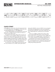
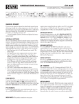
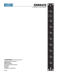
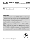
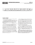
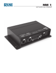
MLM42S
2
2
2
2
2
MIC & LINE MIXER
IMPORTANT SAFETY INSTRUCTIONS
1. Read these instructions.
2. Keep these instructions.
3. Heed all warnings.
4. Follow all instructions.
5. Do not use this apparatus near water.
6. Clean only with a dry cloth.
7. Do not block any ventilation openings. Install in accordance with manufacturer’s instructions.
8. Do not install near any heat sources such as radiators, registers, stoves, or other apparatus (including amplifiers) that produce heat.
9. Do not defeat the safety purpose of the polarized or grounding-type plug. A polarized plug has two blades with one wider than the other. A
grounding-type plug has two blades and a third grounding prong. The wide blade or third prong is provided for your safety. If the provided plug
does not fit into your outlet, consult an electrician for replacement of the obsolete outlet.
10. Protect the power cord and plug from being walked on or pinched particularly at plugs, convenience receptacles, and the point where it exits from
the apparatus.
11. Only use attachments and accessories specified by Rane.
12. Use only with the cart, stand, tripod, bracket, or table specified by the manufacturer, or sold with the apparatus. When a cart is used, use caution
when moving the cart/apparatus combination to avoid injury from tip-over.
13. Unplug this apparatus during lightning storms or when unused for long periods of time.
14. Refer all servicing to qualified service personnel. Servicing is required when the apparatus has been damaged in any way, such as power supply
cord or plug is damaged, liquid has been spilled or objects have fallen into the apparatus, the apparatus has been exposed to rain or moisture, does
not operate normally, or has been dropped.
15. The plug on the power cord is the AC mains disconnect device and must remain readily operable. To completely disconnect this apparatus from
the AC mains, disconnect the power supply cord plug from the AC receptacle.
16. This apparatus shall be connected to a mains socket outlet with a protective earthing connection.
17. When permanently connected, an all-pole mains switch with a contact separation of at least 3 mm in each pole shall be incorporated in the
electrical installation of the building.
18. If rackmounting, provide adequate ventilation. Equipment may be located above or below this apparatus, but some equipment (like large power
amplifiers) may cause an unacceptable amount of hum or may generate too much heat and degrade the performance of this apparatus.
19. This apparatus may be installed in an industry standard equipment rack. Use screws through all mounting holes to provide the best support.
WARNING: To reduce the risk of fire or electric shock, do not expose this apparatus to rain or moisture. Apparatus shall not be exposed to dripping
or splashing and no objects filled with liquids, such as vases, shall be placed on the apparatus.
WARNING
The symbols shown below are internationally accepted symbols
that warn of potential hazards with electrical products.
CAUTION
RISK OF ELECTRIC SHOCK
DO NOT OPEN
ATTENTION: RISQUE DE CHOCS ELECTRIQUE - NE PAS OUVRIR
To reduce the risk of electrical shock, do not open the unit. No user
serviceable parts inside. Refer servicing to qualified service personnel.
This symbol indicates that a dangerous voltage
constituting a risk of electric shock is present
within this unit.
This symbol indicates that there are important
operating and maintenance instructions in the
literature accompanying this unit.
WARNING: This product may contain chemicals known to the State of California to cause cancer, or birth defects or other reproductive harm.
NOTE: This equipment has been tested and found to comply with the limits for a Class B digital device, pursuant to part 15 of the FCC Rules.
These limits are designed to provide reasonable protection against harmful interference in a residential installation. This equipment generates, uses
and can radiate radio frequency energy and, if not installed and used in accordance with the instructions, may cause harmful interference to radio
communications. However, there is no guarantee that interference will not occur in a particular installation. If this equipment does cause harmful
interference to radio or television reception, which can be determined by turning the equipment off and on, the user is encouraged to try to correct
the interference by one or more of the following measures:
• Reorient or relocate the receiving antenna.
• Increase the separation between the equipment and receiver.
• Connect the equipment into an outlet on a circuit different from that to which the receiver is connected.
• Consult the dealer or an experienced radio/TV technician for help.
CAUTION: Changes or modifications not expressly approved by Rane Corporation could void the user's authority to operate the equipment.
This Class B digital apparatus complies with Canadian ICES-003.
Cet appareil numérique de la classe B est conforme à la norme NMB-003 du Canada.
INSTRUCTIONS DE SÉCURITÉ
1. Lisez ces instructions.
2. Gardez précieusement ces instructions.
3. Respectez les avertissements.
4. Suivez toutes les instructions.
5. Ne pas utiliser près d’une source d’eau.
6. Ne nettoyer qu’avec un chiffon doux.
7. N’obstruer aucune évacuation d’air. Effectuez l’installation en suivant les instructions du fabricant.
8. Ne pas disposer près d’une source de chaleur, c-à-d tout appareil produisant de la chaleur sans exception.
9. Ne pas modifier le cordon d’alimentation. Un cordon polarisé possède 2 lames, l’une plus large que l’autre. Un cordon avec tresse de masse possède
2 lames plus une 3è pour la terre. La lame large ou la tresse de masse assurent votre sécurité. Si le cordon fourni ne correspond pas à votre prise,
contactez votre électricien.
10. Faites en sorte que le cordon ne soit pas piétiné, ni au niveau du fil, ni au niveau de ses broches, ni au niveau des connecteurs de vos appareils.
11. N’utilisez que des accessoires recommandés par Rane.
12. N’utilisez que les éléments de transport, stands, pieds ou tables spécifiés par le fabricant ou vendu avec l’appareil. Quand vous utlisez une valise de
transport, prenez soin de vous déplacer avec cet équipement avec prudence afin d’éviter tout risque de blessure.
13. Débranchez cet appareil pendant un orage ou si vous ne l’utilisez pas pendant un certain temps.
14. Adressez-vous à du personnel qualifié pour tout service après vente. Celui-ci est nécessaire dans n’importe quel cas où l’appareil est abimé : si le
cordon ou les fiches sont endommagés, si du liquide a été renversé ou si des objets sont tombés sur l’appareil, si celui-ci a été exposé à la pluie ou
l’humidité, s’il ne fonctionne pas correctement ou est tombé.
15. La fiche du cordon d’alimentation sert à brancher le courant alternatif AC et doit absolument rester accessible. Pour déconnecter totalement
l’appareil du secteur, débranchez le câble d’alimentation de la prise secteur.
16. Cet appareil doit être branché à une prise terre avec protection.
17. Quand il est branché de manière permanente, un disjoncteur tripolaire normalisé doit être incorporé dans l’installation électrique de l’immeuble.
18. En cas de montage en rack, laissez un espace suffisant pour la ventilation. Vous pouvez disposer d’autres appareils au-dessus ou en-dessous de celuici, mais certains (tels que de gros amplificateurs) peuvent provoquer un buzz ou générer trop de chaleur au risque d’endommager votre appareil et
dégrader ses performances.
19. Cet appareil peut-être installé dans une baie standard ou un chassis normalisé pour un montage en rack. Visser chaque trou de chaque oreille de
rack pour une meilleure fixation et sécurité.
ATTENTION: afin d’éviter tout risque de feu ou de choc électrique, gardez cet appareil éloigné de toute source d’humidité et d’éclaboussures quelles
qu’elles soient. L’appareil doit également être éloigné de tout objet possédant du liquide (boisson en bouteilles, vases,…).
ATTENTION
CAUTION
RISK OF ELECTRIC SHOCK
DO NOT OPEN
ATTENTION: RISQUE DE CHOCS ELECTRIQUE - NE PAS OUVRIR
Afin d’éviter tout risque de choc électrique, ne pas ouvrir l’appareil.
Aucune pièce ne peut être changée par l’utilisateur. Contactez un
SAV qualifié pour toute intervention.
Les symboles ci-dessous sont reconnus internationalement
comme prévenant tout risque électrique.
Ce symbole indique que cette unité utilise un
voltage élevé constituant un risque de choc
électrique.
Ce symbole indique la présence d’instructions
d’utilisation et de maintenance importantes dans le
document fourni.
REMARQUE: Cet équipement a été testé et approuvé conforme aux limites pour un appareil numérique de classe B, conformément au chapitre 15
des règles de la FCC. Ces limites sont établis pour fournir une protection raisonnable contre tout risque d’interférences et peuvent provoquer une
énergie de radiofréquence s'il n'est pas installé et utilisé conformément aux instructions, peut également provoquer des interférences aux niveaux
des équipements de communication. Cependant, il n'existe aucune garantie que de telles interférences ne se produiront pas dans une installation
particulière. Si cet équipement provoque des interférences en réception radio ou télévision, ceci peut être detecté en mettant l'équipement sous/hors
tension, l'utilisateur est encouragé à essayer de corriger cette interférence par une ou plusieurs des mesures suivantes:
• Réorienter ou déplacer l'antenne de réception.
• Augmenter la distance entre l'équipement et le récepteur.
• Connecter l'équipement à une sortie sur un circuit différent de celui sur lequel le récepteur est branché.
• Consulter un revendeur ou un technicien radio / TV expérimenté.
ATTENTION: Les changements ou modifications non expressément approuvés par Rane Corporation peuvent annuler l'autorité de l'utilisateur à
manipuler cet équipement et rendre ainsi nulles toutes les conditions de garantie.
Cet appareil numérique de classe B est conforme à la norme Canadienne ICES-003.
Cet appareil numérique de classe B est conforme à la norme Canadienne NMB-003.
OPERATORS MANUAL
MLM42S
MIC & LINE MIXER
1
+6
+6
0
0
OFF
OFF
4
LOW
MID
2
HIGH
OL
+6
0
0
OFF
OFF
4
8
0
2
+6
6
10
LEVEL
LOW
MID
2
HIGH
OL
+6
0
0
OFF
OFF
4
8
0
3
+6
6
10
LEVEL
LOW
MID
2
HIGH
OL
+6
0
0
OFF
OFF
10
LEVEL
EFFECTS
4
8
0
4
+6
6
LOW
MID
OUTPUT
6
4
6
0
10
MLM42S
2
HIGH
8
0
OL
10
LEVEL
2
DRY
WET
OL
MIC/LINE MIXER
8
LEVEL
POWER
QUICK START
Sure this seems like a simple enough box. 4 Inputs, 2 Outputs
and an Effects Loop. Fine. But at least read this section to get
the best signal out of your unit and avoid potential problems.
We'll be quick, promise!
Each Input section features microphone-level XLR and linelevel ¼" TRS Inputs. Use only one Input for each channel. Both
Inputs are balanced.
If you are using condenser mics, flip the PHANTOM
POWER switches to the ON position. For dynamic mics and
line-level devices, leave these switches OFF. Phantom Power only
affects the XLR Inputs, not the ¼" TRS Inputs.
WEAR PARTS: This product contains no wear parts.
If an Input Overload indicator lights, this is your clue to
turn down its GAIN trim on the rear of the unit.
The Output Overload indicator shows the sum of the 4 Input channels, but is located before the OUTPUT LEVEL control. Therefore, the OUTPUT LEVEL control cannot correct
an Output Overload condition. Instead, turn down the LEVEL
of one or more of the Input channels. The Output Overload
indicator should remain off.
The OUTPUT MIC/LINE switch changes the balanced
XLR and TRS Outputs to either LINE-level or MIC-level. Be
aware of what sort of signal your mixer or amplifier wants to see
before you scare yourself.
FRONT PANEL DESCRIPTION
3
+6
+6
4
0
2
OFF
HIGH
EFFECTS
4
0
8
0
OL
4
+6
6
LOW
2
OFF
MID
4
6
MLM42S
0
OFF
10
LEVEL
OUTPUT
6
HIGH
8
0
OL
10
2
DRY
WET
LEVEL
1 2 3
0
OL
MIC/LINE MIXER
8
10
LEVEL
4 5 6
POWER
7
1 LOW / MID / HIGH tone controls on each input channel are Accelerated-Slope™, delivering more control, constant phase response, and less interaction between bands than normal tone controls. The LOW/MID corner frequency is 300 Hz. The MID/
HIGH corner frequency is 4 kHz. Each band allows 6 dB of boost and full cut.
2 Input Overload indicators should remain off during the loudest expected program material. If you see one light up, turn down
the rear panel Input GAIN.
3 Input LEVEL controls set the volume for each channel. These work along with the rear panel GAIN controls for maximum
signal. To achieve the smoothest mix possible, set the GAIN control on the rear panel to allow near full range operation of the mix
Level control without lighting up the Input Overload indicator.
4 EFFECTS DRY / WET control adjusts the mix between the sum of the four Inputs (DRY) and the Effects Return jack (WET).
When used with an external effects processor, the DRY/WET pan control adjusts how much processed, versus unprocessed, signal
appears in the final output mix. See the EFFECTS LOOP section on page Manual-4 for more uses.
5 Output Overload indicator is located before the Output Level control. Therefore, the Output Level control cannot be used to
correct an Output Overload condition. An Output Overload condition is corrected by turning down one or more of the Input
LEVELs. Your goal is to keep this indicator off.
6 OUTPUT LEVEL control determines the level going to all Outputs.
7 POWER indicator. When the yellow LED is lit, the MLM42S is ready to go.
Manual-2
REAR PANEL DESCRIPTION
MLM42S
MADE IN U.S.A. RANE CORP.
100-240 V
50/60 Hz 7 WATTS
OUTPUT
COMMERCIAL
AUDIO
EQUIPMENT
24TJ
EFFECTS
A
4
RETURN
3
GAIN
SEND
R
B
8
BALANCED
LINE MIC
UNBALANCED
5
67
UNBALANCED
BALANCED
LINE
OR
4
ON
MIC
PHANTOM
POWER
123
1 INPUTS 1 through 4 feature MIC-level XLR and LINE-level ¼" TRS connectors. Use only one of these Inputs for each channel.
Both Inputs are balanced. A mono ¼" TS plug may be inserted into the LINE input if necessary, but better results come from a
balanced TRS plug. See the RaneNote, “Sound System Interconnection” included with this manual.
2 GAIN trim control sets the inital gain of the Input so the front panel LEVEL control has the most latitude without distortion.
When the XLR MIC Input is used, the range of the GAIN is 12 to 50 dB and Phantom Power may be selected. When the TRS
LINE Input is used, the range of the GAIN is 0 to 12 dB and Phantom Power is disabled.
3 PHANTOM POWER switch provides 15 volts to condenser microphones plugged in the MIC Input.
4 EFFECTS SEND & RETURN loop connects external effects processors or expands to other mixers. See page Manual-4.
5 ¼" TRS and XLR Balanced OUTPUT jacks are provided for convenience. Both connectors may be used simulaneously.
6 OUTPUT LINE / MIC switch changes both balanced XLR and ¼" TRS Outputs to either LINE-level or MIC-level. Many
DJ mixers have microphone engage and talk-over functions associated with the microphone inputs. By connecting the MLM42S
directly to one of these microphone inputs, you are able to take advantage of these features.
7 A & B Unbalanced RCA Outputs provide connection to line-level inputs. The Outputs of A and B are identical.
8 Universal Voltage Input: via a miniature IEC 60320 C6 appliance inlet. This mates with an IEC 60320 C5 line cord (USA
domestic). Do not lift the ground connection!
Manual-3
BALANCED
LINE
OR
EFFECTS LOOP
The Effects loop provides a means of processing the mix of the
four Inputs. Send and Return are unbalanced ¼" TS (tip/sleeve),
so keep cable runs to these jacks as short as possible to avoid hum
and noise (under 10 feet [3 meters]). Typical effects processors
include reverb, gate, compressor, limiter, EQ, etc.
The mix of the four Inputs appears on the EFFECTS SEND
Output. This Output provides the input to the external processor.
The EFFECTS RETURN Input receives the output from
the effects processor. To prevent loss of signal when a plug is not
installed in the RETURN jack, this jack is a switching type. The
SEND is internally connected to the RETURN when a plug
is not inserted. The DRY/WET pan control allows the user to
control how much processed verses unprocessed signal appears in
the final output mix.
An alternative use for the EFFECTS loop is for Expand Output and Expand Input. For example, if you wish to use two mixers, the SEND Output of the first mixer can drive the RETURN
Input of the second mixer. The relative mix level of mixer one
versus mixer two is determined by the DRY/WET pan control of
the second mixer.
Other applications for the EFFECTS loop may use only the
SEND Output or only the RETURN Input. For example, a
drum machine, keyboard or other mono source may be connected to the RETURN Input. The relative mix of the 4 Inputs
versus the source present at the RETURN Input is determined
by the DRY/WET pan control. The SEND may be used as a
direct Output for recording.
MIC
4
MIC
3
MIC
2
MIC
1
(CHOOSE ONE,
SEND OR RETURN)
IN 1
IN 2
IN 3
IN 4
(OR)
MLM42S
SEND
RETURN
IN 3
IN 4
OUT LEFT
OUT RIGHT
FROM
KEYBOARD
AMPLIFIER OR
MAIN MIXER
OR
CD PLAYER
TO
RECORDER
OUT A
OUT B
LEFT LINE IN
RIGHT LINE IN
4 Mic Mixer, or 2 Mics and a CD Player;
Send to a Recorder, or Return a 5th Input from another mono source.
MIC
4
MIC
3
MIC
2
MIC
1
IN 1
IN 2
IN 3
IN 4
MIC
8
MIC
7
MIC
6
MLM42S
SEND
MIC
5
IN 1
IN 2
IN 3
IN 4
MLM42S
SEND
RETURN
RECORDER
RCA
OUT A
OUT B
LEFT LINE IN
RIGHT LINE IN
MAIN MIXER
XLR
OUT
MIC IN
Connecting two MLM42S's for 8 Mic Inputs
©Rane Corporation 10802 47th Ave. W., Mukilteo WA 98275-5000 USA TEL 425-355-6000 FAX 425-347-7757 WEB rane.com
Manual-4
Declaration of Conformity
Application of
Council directive(s):
Standard(s) to which
conformity is declared:
2001/95/EC
2002/96/EC
2004/108/EC
2006/95/EC
2011/65/EU
EN60065: 2002/A1:2006/A11:2008/A2:2010/A12:2011
EN55103-1:2009
EN55103-2:2009
EN50581:2012
ENVIRONMENT E2
CE MARK FIRST AFFIXED IN 2007
SERIAL NUMBERS 850000 - 950000
Manufacturer:
Rane Corporation
10802 47th Avenue West
Mukilteo WA 98275-5000 USA
This equipment has been tested and found to be in compliance with all applicable standards and regulations applying to the
EU’s Low Voltage (LV) directive 2006/95/EC, and Electromagnetic Compatibility (EMC) directive 2004/108/EC. In order
for the customer to maintain compliance with this regulation, high quality shielded cable must be used for interconnection
to other equipment. Modification of the equipment, other than that expressly outlined by the manufacturer, is not allowed
under this directive. The user of this equipment shall accept full responsibility for compliance with the LV directive and
EMC directive in the event that the equipment is modified without written consent of the manufacturer. This declaration
of conformity is issued under the sole responsibility of Rane Corporation.
Type of Equipment: Professional Audio Signal Processing
Brand: Rane
Model: MLM42S
Immunity Results:
THD+N re: 4 dBu, 400 Hz, BW=20-20kHz
Test Description
Results
Conditions
RF Electromagnetic Fields Immunity
80 MHz -1000 MHz, 1 kHz AM, 80% depth, 3V/m
< -77 dB
80 MHz - 200 MHz
< -58 dB200 MHz - 1000 MHz
Conducted RF Disturbances Immunity
150 kHz - 80 MHz, 1 kHz AM, 80% depth, 3V rms
< -77 dB
Power Lines
< -77 dBSignal Lines
Magnetic Fields Immunity
50 Hz - 10 kHz, 4.0 - 0.4 A/m
< -77 dB
I, the undersigned, hereby declare that the equipment specified above conforms
to the Directive(s) and Standard(s) shown above.
(Signature)
Roy Gill
Compliance Engineer
(Full Name)
(Position)
May 31, 2007
Mukilteo WA USA
(Date)
(Place)