1
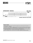
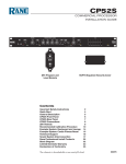
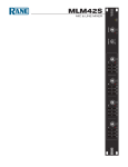
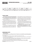
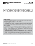
OPERATORS MANUAL
VP 12
VOICE PROCESSOR
QUICK START
Even if you don’t like to read manuals, read this part. We’ll
make it quick and painless. We promise.
Turn down (fully counterclockwise) the MIC INPUT GAIN
and both MAIN and AUX OUTPUT LEVEL controls. Set
the LOW CUT FILTER to 10 (fully CCW) and the HI CUT
FILTER to 40k (fully CW). Depress all BYPASS switches on
the front panel.
If you are using a mic, connect it to the MIC IN jack located
on the rear of the unit. If your mic requires phantom power,
press the rear panel 48V PHANTOM POWER switch. If you
are using a line level source (like the output of a wireless mic
receiver), connect its output to either the ¼" TRS jack or the
screw terminals located on the rear of the unit labeled LINE/
EXPAND IN. Leave all jumpers located on the long screw terminal patch strip in the original factory shipped position. These
positions guarantee you access to all the features of the VP 12.
Connect the Outputs of the VP 12 to your mixer board or
recorder. The switch located directly next to the XLR MAIN
OUT jack converts the MAIN OUTs to either a MIC or LINE
level output, depending on your driving requirements. The AUX
OUT of the VP 12 is only line level.
WEAR PARTS: This product contains no wear parts.
Plug the included power supply (see italics below) into the
VP 12. The yellow PWR LED will illuminate if all is well. Now
warn everyone else around, and yell into your mic the loudest
sound you expect during your session or performance. While
doing this adjust the INPUT GAIN control so that the loudest
sounds will occasionally illuminate the OL LED. If you are using the LINE IN, adjust the output level of the previous device
to occasionally illuminate the OL LED of the VP 12 when the
loudest signal you expect to hear is present.
Adjust the VP 12 OUTPUT LEVEL controls to match
the device you are driving. Now taking one processing section
at a time, release its BYPASS switch and adjust the processing
controls. Any number of processing sections may be IN or BYPASSED to isolate different parameters. For details on setting
these properly see OPERATING INSTRUCTIONS on the last
two pages.
Never connect anything except an approved Rane power
supply to the thing that looks like a telephone jack on the rear
of the VP 12. This is an AC input and requires special attention if you do not have an operational power supply EXACTLY like the one originally packed with your unit.
Manual-
FRONT PANEL DESCRIPTION
1 OL (overload) indicator LED. Illuminates (red) any time the signal is within 4 dB of overloading. Five locations are monitored.
See the block diagram with the schematics elsewhere in this manual.
2 PWR (power) indicator LED. Illuminates (yellow) when power is connected. Use only an approved RANE AC remote supply
such as an RS 1 (included) or RAP 10.
3 MIC INPUT GAIN control. Increases mic input gain as it is rotated clockwise. It’s range is 15 dB of gain at full CCW rotation
to 60 dB at full CW rotation.
4 MIC INPUT SELECT switch. In the LINE position, the signal entering LINE/EXPAND IN is active. In the MIC position the
signal entering the MIC IN is active. In the BOTH position both LINE and MIC signals are summed together. Level matching
between LINE and MIC signals must be done externally in the SUM BOTH position.
5 LOW CUT filter. Defines the low cut-off frequency. In the full CCW position the LOW CUT filter is essentially out of the
signal path.
6 HI CUT filter. This control defines the high cut-off frequency. In the full CW position the HI CUT filter is essentially out of the
signal path.
7 DE-ESS BYPASS switch. When this switch is in the DE-ESS function of the VP 12 is not functional and the DE-ESS controls
will do nothing. DE-ESS is active in the out position.
8 DE-ESS FREQUENCY. This control determines the range of frequency that the DE-ESS circuit is sensitive to. In practice it
is best to set this to the highest frequency that will provide the amount of DE-ESSING you require and no lower. The lower the
frequency setting the less transparent the DE-ESSING function becomes.
9 DE-ESS RATIO. This three-position switch determines the rate at which the DE-ESS filter responds to expected sibilance. The
NORM setting is best for most situations.
0 DE-ESS THRESHOLD control and LED. This control sets the signal level in dBu above which the DE-ESS function becomes
active. When the LED is lit, the threshold has been exceeded and the DE-ESSER is doing its thing.
Manual-
q GATE/EXPANDER and COMPRESSOR BYPASS switch. When this switch is in the GATE/EXPANDER and COMPRESSOR functions are inactive and the corresponding controls do nothing. With the switch in the out position these circuits are
active.
w GATE/EXPANDER THRESHOLD control and LED. This sets the input level below which the GATE/EXPANDER function
operates. The LED illuminates any time the signal falls below the threshold set by the control.
e GATE RATIO switch. This switch determines the ratio to be applied to the GATE/EXPANDER function. Higher ratios mean
steeper drop-off slopes, lower ratios are usually more transparent.
r COMPRESSOR THRESHOLD control and LED. This determines the input level above which the compressor functions.
Full CW rotation disables the COMPRESSOR entirely.This LED illuminates any time the signal exceeds the threshold set by the
control.
t COMPRESSOR RATIO control. This determines the slope of compression once the threshold has been exceeded. Full CCW
rotation effectively disables the compressor.
y GAIN REDUCTION METER. This seven-segment meter indicates the amount of signal reduction, below unity, applied to
the audio signal by both the GATE/EXPANDER and COMPRESSOR. The GATE/EXPANDER & COMPRESSOR BYPASS
switch has no effect on this meter, as it still shows gain reduction at current settings.
u EQ bypass switch. When this switch is in, the EQ section is not functional and the corresponding controls do nothing. In the
out position the EQ is active.
i EQ FREQUENCY control. This determines the center frequency of the bandpass equalizer.
o EQ FREQUENCY RANGE switch. This is a multiplier for the EQ FREQUENCY control. This allows each EQ to cover the
full audio range and still provide excellent resolution with a single EQ FREQUENCY control.
p EQ LEVEL control. This determines the amount of boost or cut applied to the audio signal. When this control is in the center
detent, this band of EQ is has no effect on the signal path. When this control is in grounded center detent, the band of the EQ is
out of the circuit.
Manual-
REAR PANEL DESCRIPTION
POST
PROCESSOR
IN
POWER
COMMON
COMPRESSOR/GATE
PATCH
SIDE CHAIN
PATCH
EQ
PATCH
DE-ESS
PATCH
PRE
PROCESSOR
OUT
VP 12
BALANCED WIRING:
PIN 2/TIP=POSITIVE
PIN 3/RING=NEGATIVE
PIN 1/SLEEVE=CHASSIS GND
LINE/EXPAND IN
(USE ONLY ONE)
MADE IN U.S.A.
RANE CORP.
48V PHANTOM
POWER
MAIN OUT LEVEL
BALANCED
600mA
CLASS 2 EQUIPMENT
LINE
MIC
MAIN OUT
+
-
CHAS
GND
-
AUX OUT
+
CHAS
GND
OUT
IN
OUT
CHAS
GND
IN
OUT
IN
OUT
IN
CHAS
GND
ACN001.187.837
+
CHAS
GND
-
MIC IN
1 GROUND connector. Since the VP 12 is powered from a remote AC supply which does not carry chassis ground through to the
grounding pin of the AC line cord, this screw has been provided in case your system does not have another earth grounding means
such as through rack rails, etc. Its use or disuse should be determined by your specific application.
2 REMOTE AC POWER input. The VP 12 is supplied from the factory with a Model RS 1 Remote Power Supply suitable for
connection to this input jack. The power requirements of the VP 12 call for an 18-24 volt AC center-tapped transformer only. This
is not a telephone jack. Never use a power supply with your VP 12 other than the one supplied or an exact replacement obtained from or
approved by Rane Corporation. Using any other type of supply may damage the unit and void the warranty. Two years parts and
labor is worth safeguarding, don’t you think? A three year warranty is available by completing and mailing in the warranty card,
before something goes wrong.
3 MAIN OUT LEVEL switch. Sets the output level for the MAIN output, LINE or MIC level.
4 MAIN and AUX OUTPUT XLR jacks. Are fully balanced outputs, controlled by the front panel OUTPUT LEVEL. Pin 2 is
positive, pin 3 is negative and pin 1 is chassis ground. When driving high impedance loads, both screw terminals and XLR jacks
can be used at the same time.
5 MAIN and AUX screw terminal outputs. Deliver the same outputs as the XLR connectors above.
6 Screw terminal patch strip. Configured from the factory with all functions active, in the same order as the front panel. These
terminals allow the disabling or re-arranging of functions. This also allows a function block, such as the EQ, to patch into and out
of the VP 12 to an external processor or mixing channel. The factory jumper positions are illustrated below.
7 LINE/EXPAND IN screw terminals and ¼" TRS jack. This is a line level balanced input. Tip is positive, ring is negative and
sleeve is chassis ground. Do not use both screw terminals and the ¼" TRS jack simultaneously. They do not sum.
8 MIC input. A fully balanced Mic level input. Pin 2 is positive, pin 3 is negative and pin 1 is chassis ground.
9 48V PHANTOM POWER switch and LED. When this switch is in, 48 VDC is fed to the MIC IN jack and the LED is lit.
POST
PROCESSOR
IN
CHAS
GND
COMPRESSOR/GATE
PATCH
SIDE CHAIN
PATCH
EQ
PATCH
OUT
IN
OUT
CHAS
GND
IN
OUT
DE-ESS
PATCH
IN
VP 12 Factory Jumper Positions
Manual-
OUT
PRE
PROCESSOR
OUT
IN
CHAS
GND
VP 12 CONNECTION
OPERATING INSTRUCTIONS
When connecting the VP 12 to other components in your
system leave the power supply for last. This gives you a chance to
make mistakes and correct them before any damage is done to
your fragile speakers and nerves.
The MIC input of the VP 12 is balanced and accepts a
standard XLR cable from the MIC of your choice. As with all
Rane products and AES standards, pin 2 is used for “hot” or “+”
polarity, pin 3 is “return” or “–” and pin 1 is chassis ground. If
you are not using PHANTOM POWER you may use either pin
1 or case for shield ground on the VP 12 input. However, if you
are using PHANTOM POWER, pin 1 must be shield grounded
to provide a complete electrical circuit.
The LINE/EXPAND input of the VP 12 is also balanced, as
a TRS jack or screw terminals. Choose one, these do not sum.
The tip is “+”, the ring is “–”, and the sleeve is chassis ground.
Unbalanced wiring such as a standard ¼" TS plug may also
work, but with possible compromises in level adjustments.
Outputs on the VP 12 are fully balanced. As expected, pin
2 is “hot” or “+”, pin 3 is “return” or “–” and pin 1 is chassis
ground. If unbalanced operation is required then simply connect
to the “+” and ground connections on the screw terminals, or
leave pin 3 unconnected on the XLR output connectors.
Refer to the RaneNote “Sound System Interconnection”
included with this manual for further information on wiring.
As with any piece of gear that includes this many features,
you can quite easily mess up the sound that you really meant to
improve. The features of the VP 12 are arranged in an order from
the factory, if followed, can make setting up properly an easy
operation. It is easier to start with all BYPASS switches in the in
position, and add one process at a time. If a particular processing
section does nothing to improve the sound, BYPASS it!
INPUT SECTION
If you are using the MIC input only, set the front panel
switch to the MIC position. When setting up the MIC input
section, always take as much gain as possible right at the input.
Therefore, the highest level audio from the MIC INPUT should
just barely light the OL LED. We call this tickling the overload.
This may be illegal in your jurisdiction so please check your local
authorities. If only the LINE/EXPAND input is to be used, set
the front panel switch to LINE. Adjust the output level on the
previous device to just light the OL LED of the VP 12 when
receiving the largest signal you expect. Make sure that the previous device is not being overloaded by checking its OL sensor. To
use both the MIC input and LINE/EXPAND input, set up each
input as described above, then set the INPUT SELECT switch
to sum BOTH. Verify no OL condition exists with the loudest
signal fed to both inputs simultaneously.
CUT FILTERS
Cut filters can improve the signal to noise performance of
your equipment. For example, rolling off some of the low end by
adjusting the LOW CUT FILTER gets rid of the noise caused by
wind blowing across your MIC. Or if previous equipment is less
than perfect when it comes to high frequency hiss, roll it off by
adjusting the HI CUT FILTER.
DE-ESSER
The DE-ESSER can be somewhat tricky to set up but here
are some helpful hints. The DE-ESSER can be set for multiple
people with moderate control, or if one person speaks with some
nasty sibilance, the DE-ESSER offers even more control. To get
started, set the DE-ESSER controls for a frequency of 6 kHz,
RATIO of NORM, and a THRESHOLD of -30. Make sure the
BYPASS switch is out. Now speak the sibilance mantra, “Silly
Sally (or Sam depending on your gender bias) sells sea shells by
the sea shore”, into the mic. While saying this (over and over
until those listening make terrible threats) look at the front of the
VP 12 and monitor the DE-ESS THRESHOLD LED. The DEESSER does nothing until that LED lights up. Notice the sound
quality coming out of your system when the LED is on. Your
mission is to adjust the controls so that sibilance is controlled,
but does not degrade the sound quality. All frequencies above the
setting on the FREQUENCY control are being level monitored.
A setting of 9 kHz is for very light DE-ESSING, 700 Hz is for
extreme DE-ESSING. The RATIO switch sets the amount of
band limiting for a given signal level above the threshold. The
THRESHOLD control establishes the signal level point that
must be exceeded before DE-ESSING occurs. A setting of 20
defeats the DE-ESSING function.
Manual-
GATE/EXPANDER and COMPRESSOR
A noise GATE (sometimes referred to as a downward expander) extends the dynamic range of the signal by effectively
lowering the noise floor. All signals that are lower in level than
the setting on the GATE/EXPANDER THRESHOLD control
are attenutated at the selected ratio. When the RATIO switch is
set for 1.5:1, a 1 dB reduction in input level results in a 1.5 dB reduction in output level. For a 2:1 setting, a the same 1 dB input
level reduction results in a 2 dB reduction in output level.
A good place to start with the GATE/EXPANDER is to
insure the BYPASS switch is out. Set the THRESHOLD control
to about -40 and the ratio to 1.5:1. Now apply the smallest signal
that you want to be processed by subsequent stages. An example
would be to talk softly into the MIC input. While talking,
notice that the THRESHOLD LED goes off and the GAIN
REDUCTION METER shows no gain reduction — this is
good. If the threshold LED stays on when talking softly, then
turn the THRESHOLD control CCW. The THRESHOLD
control is properly set when the lowest level signal to process
makes the THRESHOLD LED go off, and when that low
signal is removed the THRESHOLD LED comes back on, and
the GAIN REDUCTION meter shows gain reduction. Set the
GATE RATIO switch for the lowest ratio that provides the
amount of control desired. A setting of 1.5:1 allows for gentle
gain reduction below the threshold while a setting of 3:1 is more
detectable. For minimum effect set the GATE RATIO switch to
1.5:1 and set the THRESHOLD for -50.
The Compressor is familiar to anyone who has used Rane’s
darn cool DC 24 DYNAMIC CONTROLLER. While the
GATE/EXPANDER controls those signals lower in level than
your threshold setting, the COMPRESSOR controls those
signals above your COMPRESSOR THRESHOLD setting.
Once again, make sure that the BYPASS switch is out. Set the
COMPRESSOR THRESHOLD control to 20 and the COMPRESSOR RATIO to about 1.6:1. Now apply the largest signal
to be unaffected by the COMPRESSOR. This establishes the
highest signal level that will not be affected by the compressor
circuit. Adjust the THRESHOLD control CCW while talking
loudly or yelling. Stop adjusting the THRESHOLD control
when the THRESHOLD LED comes on. This is a good starting
point. A setting of 20 on the COMPRESSOR THRESHOLD
removes it’s effectiveness. The RATIO control sets the severity of
compression. A setting of 1:1 means no compressing (even if the
threshold LED is on), while a setting of 10:1 is very much like a
limiter, and will result in only a 1 dB increase in output level for
a 10 dB increase in input level.
EQUALIZER
If you have used Rane’s PE 17 equalizer, then the EQ in the
VP 12 will look familiar. Adjust the FREQUENCY control
to the desired frequency, adjust the BW control for a range of
frequencies, and then adjust the LEVEL to either boost or cut.
For simple tone contours all you need to do is adjust the BW
control to a larger number like 2.0, and now you have affected a
broad range of frequencies. BW is measured in octaves, and each
doubling or halving of a frequency equals one octave. Adjusting the FREQUENCY range switch selects multiples of the
FREQUENCY control, allowing each band to cover the full 20
Hz to 20 kHz range while maintaining resolution of the FREQUENCY control.
The two bands are in series. This allows the two EQ sections
to add together. For a serious notch, for instance, adjust both sets
of controls to the same settings. Both LEVEL controls set at -15
dB deliver one serious -30 dB notch.
OUTPUT METER and LEVEL CONTROLS
The six segment output meter indicates the level coming
out of the VP 12. It is calibrated in dBu and is referenced to a
balanced output. If the output wiring is unbalanced, your actual
output will be 6 dB lower than that shown on the meter.
The LEVEL controls utilize a concentric potentiometer to
control two separate outputs or zones. The farthest out (inner)
knob controls the MAIN OUTPUT and the farthest in (outer)
knob controls the AUX OUTPUT.
©Rane Corporation 10802 47th Ave. W., Mukilteo WA 98275-5098 TEL 425-355-6000 FAX 425-347-7757 WEB www.rane.com
Manual-
103144