1
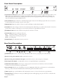
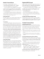
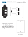
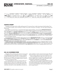
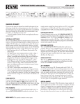
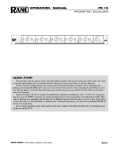
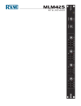
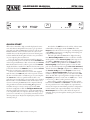
HARDWARE MANUAL
RPM 26z
PROGRAMMABLE MULTIPROCESSOR
1
2
INPUT
LOCK
A
AES3
B
1
2
3
4
5
6
OUTPUT
24
PRESET
RPM 26z
PROGRAMMABLE
MULTIPROCESSOR
VIP
ETHERNET STATUS
POWER
QUICK START
This section is intended to help you make the physical connections and software manipulations necessary to get up and running with your sleek new RPM 26z. If you don’t read the entire
Hardware Manual, at least read this section. It is also recommended that you read the Quick Start section of the Drag Net
Software Manual. If the Drag Net software is not yet installed
on your computer, please install it now.
To be safe, leave the audio connections until last. Begin by
connecting the IEC power cord. Observe that the POWER LED
on the front panel illuminates. After a few seconds, the STATUS
LED should turn from red to yellow to green, and the PRESET
display should have a number in it (00, if it’s the first time you’ve
powered the device). If the POWER comes on, but the STATUS
LED does not turn green, contact the factory.
Connect one end of the Ethernet crossover cable (supplied
with the unit) to the 10Base-T jack on the rear panel. Connect
the other end of the cable to an Ethernet port on your computer.
The LINK LED on the rear panel should be lit. If it is not,
verify that you are indeed using a crossover cable, not a standard
Ethernet cable. A standard Ethernet cable should only be used
if you are connecting the RPM 26z and a computer indirectly
using an Ethernet switch. Launch the Drag Net application
and follow the steps to create a new project and new RPM
26z device configuration. Click the Configure Hardware IP
shortcut and follow the instructions to set the unit’s IP address
to be compatible with your computer’s Network settings. Tip: If
you aren't sure what IP to use, try the address 192.168.69.69 and
subnet 255.255.255.0. This finds the default factory address without
manually setting it.
WEAR PARTS: This product contains no wear parts.
Now click on the Poll button in the toolbar. A device name
and IP address should appear under the Live folder in the
Project window. If a device does not appear, consult Drag Net’s
online Help for instructions on configuring and verifying your
computer’s Network settings.
The audio path within the RPM 26z is displayed in Drag
Net’s Device Configuration window as a collection of blocks
wired together to form a Processing Map. These maps are created offline as Storage configurations, which are then transferred to a Live unit. Drag blocks from the Palette onto the
Processing Map and wire them together to create the audio
path. Save this file frequently using the File > Save command.
Transfer the selected Storage configuration to a Live unit using
the Transfer Config button in the Project window. A new,
minty green Device Configuration window opens once the
transfer is complete, indicating you are now online with a Live
device. Double-click a processing block to display and adjust its
Properties (parameters) in real time on a Live device — there
is no need to go offline to make parameter changes.
Once you have a useful configuration in the unit, connect
balanced audio INPUTS and OUTPUTS to the Euroblocks on
the rear panel, then turn on the amplifier. As a precautionary
measure, all outputs are muted during and after a configuration
transfer. Unmute each output individually, or use the handy
Mute Outputs button in the toolbar. Once all outputs are
unmuted, audio passes through the unit along the connections
you defined.
Manual-1
Front Panel Description
1
2
LOCK
A
B
1
3
2
4
5
24
6
RPM 26z
PROGRAMMABLE
MULTIPROCESSOR
INPUT
AES3
OUTPUT
PRESET
VIP
1
2
1
3
4
ETHERNET STATUS
POWER
5 6 7
1 Signal/Overload LED meters indicate the presence of significant audio signal or overload for Inputs and Outputs. These 3-color
meters indicate the available headroom once the analog signal has been converted to digital: -4 dBFS (red, near clipping), -12
dBFS (yellow, high normal level), and -48 dBFS (green, low level). The analog signal level depends on the input and output settings and is displayed in Drag Net’s Meter window.
2 AES3 LOCK LED lights solidly when a valid AES3 digital signal is detected on the AES3 input jack. There does not need to be
an audio signal present at the input, only the “carrier” signal.
3 PRESET LED displays the number of the most recently recalled Preset, numbered 0 through 24.
4 VIP LED flashes when a change is detected on the Versatile Input Port (VIP). This port is used for direct electrical connections to
potentiometers, switches or other logic ports. See Control Connections on page Manual-4 for details.
5 ETHERNET LED flashes when an Ethernet data packet for this device is received.
6 STATUS LED reflects the overall status of the unit:
Red
- initializing (briefly) or possible internal error.
Yellow - working, but not currently processing audio.
Green - processing audio.
7 POWER LED lights solidly when the unit is powered on.
Rear Panel Description
RPM 26z
MADE IN U.S.A.
RANE CORP.
COMMERCIAL AUDIO
EQUIPMENT 24TJ
10Base-T
AES3 INPUT
VERSATILE INPUT PORT
0-5V
+5V
100 mA
DEFAULT
1
6
5
4
3
2
1
2
1
2
3
4
5
6
7
8 REF GND
+ –
+ –
+ –
+ –
+ –
+ –
+ –
+ –
1
2
3
4
5
6
7
8 REF GND
+ –
+ –
+ –
+ –
+ –
+ –
+ –
+ –
THIS DEVICE
COMPLIES WITH PART
15 OF THE FCC RULES
FOR A CLASS 'B'
COMPUTING DEVICE.
LAN LINK
ACN 001 345 482
8
INPUTS
1
R
100-240V
50/60 Hz 20 WATTS
OUTPUTS
7
6
4
5
3
2
1 POWER IEC jack connects to AC line voltage, 100-240 VAC ±10%. Use the 3-prong IEC power cable (included).
2 Balanced analog audio INPUTS 1 and 2 on Euroblock connectors.
3 Balanced analog audio OUTPUTS 1 through 6 on Euroblock connectors. Same wiring notes as the Inputs.
4 AES3 digital audio INPUT is an XLR female connector. See Digital AES3 Input on page Manual-3.
5 VERSATILE INPUT PORT provides 8 logic or voltage inputs for remote level control and Preset recall on a Euroblock
connector. See Control Connections on page Manual-4.
6 LAN and LINK reflect the state of the Ethernet connection. LINK lights solidly when a valid connection to another Ethernet
device (e.g., a PC) is detected. LAN flashes when communicating with another Ethernet device.
7 10Base-T jack accepts a standard Ethernet cable with a RJ-45 connector. See Control Connections on page Manual-4.
8 DEFAULT button recalls Preset 1 when pressed. Holding this button while applying power puts the unit into a codeload mode
for updating firmware.
Manual-2
Audio Connections
Digital (AES3) Input
For each Input or Output Euroblock connector:
• Connect the (positive) audio line to the ‘+’ terminal.
• Connect the (negative) audio line to the ‘–’ terminal.
• Connect the cable shield to the ground terminal.
For those installations where the RPM 26z’s internal shieldto-chassis connection causes interference, connect each shield
directly to the chassis PEM nut located above each Euroblock
connector, keeping the shield wrapped around the audio conductors as much as possible.
For optimum Electromagnetic Interference (EMI) immunity,
connect the shields at both ends of the cable. See the RaneNote
“Sound System Interconnection” for more information on system
connections and proper grounding practices.
AES3 is a popular 2-channel (stereo) digital audio interface commonly found on professional digital audio equipment (digital
mixers, DAT machines, etc.). Each channel of the AES3 digital
stream is treated independently within the RPM 26z.
See the RaneNote “Interfacing AES3 and S/PDIF”, available
from Rane’s web site (www.rane.com/library.html), for more
information about interfacing consumer S/PDIF gear to the
professional AES3 standard.
Use the AES3 Input to:
• Connect from the AES3 Ouput of an RPM 88/44/22.
• Connect directly from the AES3 output of a digital mixer.
• Connect to an external A/D converter, effectively adding two
more analog inputs.
Analog Input Stage
Each analog input uses a two-stage gain approach. The first stage
contains a variable gain preamp. The second stage contains a
Digital Trim control located immediately after the A/D converter.
Incoming Sample Rate and Word Length
The AES3 input has a built-in sample rate converter capable of
accepting incoming sample rates up to 96 kHz. Sample rates exceeding the RPM 26z’s internal 48 kHz sample rate are automatically downsampled. Word lengths up to 24-bits are accepted.
Input Clipping
If you’ve set the Analog Gain so the input stage is not clipping, it is not possible to clip the A/D converter, since there is no
additional gain between the initial input stage and the A/D converter. The Digital Trim control, located after the A/D converter,
can be set to clip the signal to your heart’s content, so adjusting
this trim to provide the hottest signal to the DSPs without clipping is the most important step when setting up gain structure.
For this reason, a dedicated meter displaying the signal level being passed to the DSPs is provided in each Analog Input block.
If the DSPs are working with a clipped signal, the audio is (as
expected) distorted and none too pretty, but it is not a drastic,
damaging sound. And while it’s technically possible to write a
DSP algorithm to emulate the glorious clipping distortion of
vacuum tubes, it’s not particularly useful for an installed sound
system, where the DSP power could be put to better use removing that annoying 500 Hz feedback from the podium mic. Plus,
they don’t yet make DSP chips with gold-plated substrates for
those celestial highs and that moist, supple midrange.
Analog Output Stage
Each analog output also uses a two-stage gain approach, which
differs slightly from that of the analog input stage. The first stage
is a Digital Trim control located immediately before the D/A
converter. The second stage is an analog trim control located immediately after the D/A converter. Attenuation is handled in the
analog domain, while boosting (when the incoming digital signal
is low) is handled in the digital domain. Boosting and attenuating using this two-stage approach helps maintain the RPM 26z’s
excellent noise performance.
Control Connections
Versatile Input Port (VIP)
Eight logic input pins are provided, each capable of accepting
DC voltage between 0-5 VDC. VIP pins are used with contact
closure switches for Preset recall, or with potentiometers for
remote Level control. The functionality (Preset recall versus
control) of each pin is assignable as part of the Device Configuration.
• The maximum allowable voltage on any VIP pin is 5.3 VDC.
• Use of twisted pair cable is recommended for better noise immunity.
• If an external device is used to generate a 0 to 5 volt signal,
connect the ground of the external device to the GND pin of
the VIP.
Preset Recall Using Contact Closure Switches
The minimum “low” voltage required to detect a contact closure
and change Presets is 2.5 V. Since the internal pull up is 100 kΩ
to +5 V, it is possible to calculate the maximum allowable cable
length, provided the wire resistance per foot (or meter) is known.
Example:
To be safe, let’s allow a maximum of 80 kΩ worth of cable
resistance. This value keeps the voltage divider formed by the
100 kΩ internal resistance and 80 kΩ cable resistance from
dropping below 2.5 V.
(5 V * 100 kΩ) / (100 kΩ + 80 kΩ) = 2.777 V
If the cable resistance is 30 Ω per 1,000 feet (305 meters)
(1,000 ft / 30 Ω) * 80,000 Ω = 2,666,666 ft (813 km)
Thus, you can only use 2,666,666 feet (505 miles) of twisted
pair cable before the Preset recall functionality becomes intermittent (assuming the cable is properly twisted and not run
through excessive magnetic or electric fields).
Manual-3
Remote Level Control Using Potentiometers
The VIP inherently prefers linear taper 10 kΩ potentiometers,
which provide a nice audio taper “feel” for the end user. When
used with suitable twisted pair wiring, the 10 kΩ value also offers acceptable noise immunity and very long cable lengths.
AMX and Crestron Control
There are two ways to control a Drag Net device from an AMX
or Crestron system. Use either Ethernet connectivity or use the
rear panel Versatile Input Port (VIP). Each of the 8 VIP pins
supports either switch closure Preset recall or zero-to-five volt
control of Level.
Many AMX/Crestron applications require simple Level control and/or Preset recall. This is most easily accomplished using
the VIP (Versatile Input Port) found on all Drag Net devices.
VIP Preset Recall
Connect a switch closure or relay to a VIP pin and short it to
the ground (GND) pin to recall the corresponding Preset. For
example, shorting VIP pin 1 to the GND terminal recalls Preset
1; pin 2 recalls Preset 2, etc. There are more details about this
functionality in the Drag Net Help file and on our Drag Net
web page. Be certain to appropriately set the VIP Allocation in
Drag Net's Parameter Window.
If GND contention of two or more pins simultaneously
occurs, the highest-numbered VIP pin takes precedence. For
example, if pin 3 is shorted to GND and pin 6 is then shorted
to GND, Preset 6 is recalled. If pin 3 is closed and then pin 2,
nothing happens -- Preset 2 is not recalled. This permits a hierarchy of Presets when using VIP pin closures for tiered priority
paging. Since there are only eight VIP pins, you can only recall
up to eight Presets using switch closures.
There are two ways to recall more than eight presets.
1. Use the Drag Net software Recall button which is only intended for the system installer/designer.
2. Use an Ethernet command from an AMX or Crestron Ethernet-equipped product.
[When using Drag Net's Auto Mixer/Ducker block, you have
the ability to link a VIP pin closure to a push-to-talk switch in a
paging or boardroom application. When using the Ducker block
in these applications, the VIP pins act independently provided
you Group the appropriate VIP pin with the Auto Mixer/Ducker's Input in Drag Net's Remote Map. Again, see our Drag Net
Applications for examples.]
VIP CONNECTION
(examples for VIP pin 1)
REF
pin 1
20 kΩ (linear)
pin 1
GND
Contact
Closure
GND
Potentiometer
Level Control
VIP Level control
Connect a zero to five volt DC voltage to a VIP pin from an
AMX or Crestron card to adjust any or all Level blocks placed in
the Processing Map. Use Groups in Drag Net's Remote Map to
link one or more Level blocks so they track each other when using a VIP pin. Be certain to appropriately set the VIP Allocation
in Drag Net's Parameter Window. When using VIP pins with
Level blocks, set the minimum and maximum for each Level
block by double-clicking it while it's in a Remote Map Group.
This keeps the max and min burdens within the Drag Net device
— but only when using the VIP pin to control Levels, not when
adjusting Levels from Ethernet commands.
You can use up to eight voltage control inputs linked to
Level(s) using the rear panel VIP pins. Combinations of Preset
switches & voltage Level “pots” are possible as long as combined,
they do not exceed the eight pins provided.
Since you can Group any or all Level blocks in Drag Net's
Remote Map, it's much easier to implement a stereo level control
since the Drag Net device is burdened with the task of tracking
many Levels. You can use this to your advantage when using VIP
pins to adjust multiple zones or levels. Since you can place the
Level block anywhere within the Drag Net Processing Map, you
can Group Level blocks at the input, at the output or anywhere
in-between — just place the Level block where you want it.
Ethernet control
To download the AMX or Crestron control code and documentation, visit www.rane.com/dragnet
Ethernet Port
The Ethernet port is used to configure, monitor, and control the
RPM 26z via standard 10Base-T Ethernet communication. Use
an Ethernet crossover cable (one is included with each unit) to
connect the RPM 26z directly to a computer. Use a standard
(non-crossover) Ethernet cable if the RPM 26z and computer are
connected indirectly using an Ethernet repeater hub or switch.
All devices connected to the Ethernet port, including
repeater hubs, switches, and the computer’s Network Interface
Card (NIC) must support 10Base-T communication.
©Rane Corporation 10802 47th Ave. W., Mukilteo WA 98275-5098 USA TEL 425-355-6000 FAX 425-347-7757 WEB www.rane.com
Manual-4
111216