1
VISTA XM
SERIES
TECHNICAL REFERENCE
MANUAL
WWW.DIYALARMFORUM.COM
CONGRATULATIONS
- and WELCOME to the VISTA XM FAMILY!
The purpose of this TECHNICAL REFERENCE MANUAL is to give you, the installer, a
better understandingof the operationand capabilities of the VISTA XM Seriesof products.
From the most basic configuration to the most complex, this manual will help you fully
understand each option, step-by-step. The manual defines the system components,
provides spec.ific wiring and programming instructions (complemented with numerous
diagrams) and describesthe system’soperation. In addition, a comprehensiveglossary is
included to help avoid confusion with the system’sstate of the art terminology.
As always, ADEMCO is there for YOU! Our SALES and TECHNICAL SUPPORT staff
are eagerto assistyou in any way they can, so don’t hesitateto call, for any reason!
East Coast Technical Support: l-800-645-7492 (8 a.m.-6 p.m. EXT.)
West Coast Technical Support: 1-800-458-9469 (8 a.m.-5 p.m. P.S.T.)
Again, CONGRATULATIONS, andWELCOME ABOARD!
1 NOTE: THIS ISSUE HAS BEEN SUBSTANTIALLY REVISED.
ADEbfCO’s
VISTA
XM
SERIES
TECHNICAL
REFERENCE
MANUAL
WWW.DIYALARMFORUM.COM
1
3
TABLE OF CONTENTS
I.
II.
GENERAL
HARDWARE
A
B.
C.
D.
E.
F.
G.
H.
Ill.
IV.
V.
1:
11
11
12
.15
16
17
SYSTEM
.21
I:
25
30
.36
CONFIGURATION
(ZONES) .........................................................
BASIC 9 HARD-WIRED ZONES ................................................................................
ZONE EXPANSION MODULE ..................................................................................
P-WIRE POLLING LOOP EXPANSION ......................................................................
WIRELESS ZONE EXPANSION ...............................................................................
ZONE EXPANSION COMBlNATlONS .............. . ........................................................
SYSTEM
VIII. SYSTEM
........................................97
PROCEDURES
37
36
41
43
.45
47
48
..............................................................................49
49
.49
54
THE SYSTEM ...............................................................................55
OPERATION
.........................................................................................
57
SECURI-W ACCESS CODES ....................................................................................
KEYPAD FUNCTIONS ...........................................................................................
TROUBLE CONDITIONS ..........................................................................................
RECALLING ALARM/TROUBLE MESSAGES.. ..........................................................
SYSTEM
A.
8.
(PERIPHERALS)
MOUNTING THE 4140XM CABINET ...........................................................................
MOUNTING THE 413OXM/513OXM CONTROLS.. ......................................................
ADJUSTING THE ALPHA CONSOLE LCD VIEW ANGLE ...........................................
POWERING
A.
B.
C.
D.
CONFIGURATION
REMOTE CONSOLES ..............................................................................................
EXTERNAL SOUNDERS ..........................................................................................
SMOKE DETECTOR CONFlGURATlONS ..................................................................
PASSIVE INFRARED MOTlON DETECTORS (PIRs) ...................................................
PHONE LINE INTERFACE.. .....................................................................................
AUXILIARY VOLTAGE TRIGGERS .............................................................................
REMOTE KEYSWITCH OPERATlON 8 WIRING ..........................................................
MOUNTING
A.
B.
C.
IX.
OVERVIEW .......................................................................................9
VlSTA XM CONTROL PANELS ...................................................................................
REMOTE CONSOLES 8 KEYSWlTCH.. .....................................................................
DIALERS .................................................................................................................
2.WIRE SMOKE DETECTORS.. ................................................................................
P-WIRE POLLING LOOP DEVICES ............................................................................
WIRELESS DEVlCES.. ............................................................................................
SOUNDERS .............................................................................................................
MISCELLANEOUS ACCESSORIES.. ........................................................................
A.
B.
C.
D.
E.
k
VII.
....................................................................................7
ZONE TYPE DEFINITIONS ................................................................................19
A.
B.
C.
D.
E.
VI.
INFORMATION
COMMUNICATIONS
.........................................................................63
DIGKAL COMMUNICATOR OPERATION ..................................................................
COMMUNICATION FORMATS ..................................................................................
ADEMCO’s
57
..4 9
.61
62
VISTA Xbf SERIES TECHNXCAL
REFERENCE
MANUAL
WWW.DIYALARMFORUM.COM
.63
.64
4
TABLE OF CONTENTS (cont.)
X.
PROGRAMMING
A.
;:
ii:
E
H:
I;
K-.
L.
ri
0.
THE SYSTEM ........................................................-.........-....71
GENERAL INFORMAnON ........................................................................................
SECURITY ACCESS CODES.. ..................................................................................
ZONE DEFINlTlONS .................................................................................................
RF OPTIONS ............................................................................................................
SYSTEM OPTIONS ..................................................................................................
SOUNDER OPTIONS ..............................................................................................
TELEPHONE OPTIONS ...........................................................................................
REPORTING OPTIONS ............................................................................................
SELECT REPORTING FORMAT.. .............................................................................
3+1/4+1 STANDARD OR EXPANDED REPORT SELECTION .....................................
ZONE CHANNEL ASSIGNMENTS .............................................................................
REPORT CODES .....................................................................................................
4+2 EXPANDED FORMAT EVENT/ID CODES ...........................................................
DOWNLOADING OPTIONS .......................................................................................
PROGRAMMING ZONE DESCRIPTIONS ..................................................................
Xl.
DOWNLOADING..
XII.
TESTING
XIII. SPECIAL
THE
XV.
SYSTEM.. .................................................................................103
UL REQUIREMENTS..
........................................................................................I 13
SUMMARY-
113
114
.115
.116
118
OF TERMS.. ..................................................................................I 19
XVI. SPECIFICATIONS
XVII.
...................................................................105
CONSOLES.. .........................................................................................................
HARD-WIRED ZONES, 1-9.. ....................................................................................
RPMs.. ..................................................................................................................
WIRELESS ...........................................................................................................
COMMUNICATIONS ...............................................................................................
GLOSSARY
i:
94
.95
...................................................................................................99
XIV. TROUBLESHOOTING
A.
B.
C.
D.
E.
71
75
76
78
. 0
.83
04
-87
.88
89
91
...............................................................................................123
OF CONNECTIONS
& PROGRAMMING
DEFAULTS.129
A. SUMMARY OF CONNECTIONS.. ............................................................................
8. PROGRAMMING DEFAULT VALUES ......................................................................
ADEMCO’s
VISTA
XM SERIES
TECHNICAL
REFERENCE
MANUAL
WWW.DIYALARMFORUM.COM
.129
132
5
LIST OF DIAGRAMS
1.
2A.
28.
3.
4.
5.
6.
7.
8.
9.
10.
11.
12.
13.
14.
15.
16.
17.
18.
19.
20.
21.
22.
23.
24.
25.
26.
27.
28.
29.
30.
31.
32.
33.
34.
35.
36.
37.
38.
39.
40.
41.
42.
43.
44.
45.
21
P-WIRE SMOKE DETECTOR HOOK-UP ..............................................................................................
22
ZONES 2-8 EOLR SUPERVISED CONFIGURATION ............................................................................
.22
ZONES 2-8 CLOSED-CIRCUlT UNSUPERVISED CONFIGURATIONS.. ................................................
.23
ZONE 9 FAST RESPONSE - UNSUPERVISED ONLY.. .......................................................................
-24
4152LMB INSTALLATION 8 WIRING ..................................................................................................
-25
ZONE EXPANSION DIAGRAMS .........................................................................................................
26
4197 POWER CONNECTIONS ...........................................................................................................
-27
LEFT/RIGHT
ZONES
...........................................................................................................
419OWl-l
. ............................................
.28
4208 SUMMARY OF CONNECTIONS.. ..................................................
.31
4280 AND 4280-8 RF RECEIVERS ....................................................................................................
33
SINGLE WIRELESS RECEIVER CONFIGURATION ..............................................................................
...........................................................
33
TWO WIRELESS RECEIVERS REDUNDANT CONFIGURATION
34
TWO WIRELESS RECEIVERS TO INCREASE COVERAGE. ................................................................
.36
ZONE EXPANSION COMBINATION CONFIGURATIONS ......................................................................
.37
CONSOLE
HOOK-UP..
.......................................................................................................
REMOTE
.38
SOUNDER OPTIONS FOR 4140XM CONTROL ..................................................................................
39
SOUNDER OPTIONS FOR 5130XM OR 4130XM CONTROLS ..............................................................
.39
4148 RELAY MODULE.. ....................................................................................................................
40
TWO 702 SIRENS IN SERIES ..............................................................................................................
40
TWO 719 SIRENS IN PARALLEL.. ......................................................................................................
...4 1
ZONE 1 EOLR SUPERVISED FOR BWIRE SMOKE DETECTORS ....................................................
.41
ZONES 2-8 EOLR SUPERVISED FOR 4-WIRE SMOKE DETECTORS .................................................
.42
P-WIRE POLLING LOOP SMOKE DETECTORS.. ................................................................................
.42
RF SMOKE DETECTORS.. ................................................................................................................
.43
4196 POLLING LOOP PIR .................................................................................................................
4275 POLLING LOOP PIR ...............................................................................................................
...4 4
.44
5775 WIRELESS PIR.. .......................................................................................................................
INSTALLING THE 4171XT-XM DIALER WlTH THE 4130XM15130XM CONTROLS ................................. .45
.46
PHONE LINEAND GROUND START CONNECTlONS .........................................................................
4171XT-XMI4171XM AUXILIARY VOLTAGE TRIGGERS ......................................................................
.47
.48
KEYSWlTCH WIRING .........................................................................................................................
SURFACE MOUNT INSTALLATIONS ..................................................................................................
50
51
FLUSH MOUNTING - BASIC ...............................................................................................................
INSERTING THE NAMEPLATE ..........................................................................................................
..5 2
.53
FLUSH MOUNTING WlTH TRIM RING ..................................................................................................
54
PRE-WIRUNEW CONSTRUCTION.. ....................................................................................................
55
POWER FLOW CHART .......................................................................................................................
POWER PACK AND BAlTERY CONNECTlONS ..................................................................................
58
I 05
4140ATX UL GRADE A INSTALLATION.. ............................................................................................
.I06
UL GRADE AA 4140ATX CONNECTED TO 698UL DERIVED CHANNELSTU.. ....................................
I 07
UL GRADE AA TAMPER CIRCUIT WITH A 698UL STU.. .......................................................................
UL GRADE A4140ATX CONNECTED TO A 7621AD LONG RANGE RADIO TRANSMllTER ................. 108
UL GRADE AA INSTALLATION USING A 445 HIGH LINE SECURITY TRANSMITTER.. .......................... .109
UL GRADE A CENTRAL STATION INSTALLATION USING A 346 POLICE CONNECTlON ..................... ,110
414OXM SUMMARY OF CONNECTIONS DIAGRAM .............................................................................
130
131
4130XM15130XM SUMMARY OF CONNECTIONS ...............................................................................
ADt?btCO’r
VISTA XM SERIES TECHNICAL
REFERENCE
btANVAL
WWW.DIYALARMFORUM.COM
6
LIST OF TABLES
1.
2.
3.
4.
5.
6.
7.
8.
9.
10.
11.
12.
13.
14.
15.
DIP SWlTCH TABLE, POLLING LOOP DEVICES.. ................................................................................
DIP SWITCH TABLE, WIRELESS DEVICES ...........................................................................................
BATTERY STANDBY TABLE ................................................................................................................
CONTACT ID REPORTlNG CODE DEFlNlTlONS ...................................................................................
LOW SPEED DIGITAL COMMUNICATOR MESSAGE FORMATS.. .........................................................
SUMMARY OF PROGRAMMING COMMANDS ......................................................................................
INDEX TO PROGRAMMING FIELDS .....................................................................................................
VOCABULARY OF WORDS STORED IN MEMORY ................................................................................
AUXILIARY CURRENT DRAW WORKSHEET.. ......................................................................................
POLLING LOOP CURRENT DRAW WORKSHEET.. .............................................................................
STANDARD PRE-PROGRAMMED DEFAULTS.. ........................... .......................................................
STANDARD LOW SPEED 3+1/4+1 PRE-PROGRAMMING.. .................................................................
EXPANDED LOW SPEED 3+1&l PRE-PROGRAMMING.. .................................................................
ADEMCO HIGH SPEED PRE-PROGRAMMING ....................................................................................
4+2 EXPANDED FORMAT PRE-PROGRAMMING ................................................................................
-29
35
55
.66
.70
.73
.74
98
.129
.129
.132
.143
.145
.147
.149
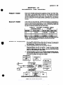
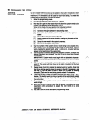
SEVEN STEPS TO EASY INSTALLATION
The following steps are required to properly install a VISTA XM system:
STEP
1
STEP
2
STEP
3
STEP
4
STEP
6
STEP
6
STEP
7
ADVlSORtES
MODEL
NUMBERS
Become familiar with the system by reading the GENERAL INFORMATION section.
Determine the hardware required for the installation by reviewing section II:
HARDWARE OVERVIEW.
Determine the system’s zone configuration and wiring requirements by reviewing
section Ill: ZONE TYPE DEFINITIONS, section IV: SYSTEM CONFIGURATION
(ZONES) and section V: SYSTEM CONFIGURATION (PERIPHERALS). If the
installation is UL rated, check the special UL requirements in section XIII.
Once the wiring is completed, mount the Control and make power connections
following the instructions provided in section VI: MOUNTING PROCEDURES and
section VII:’ POWERING THE SYSTEM.
Learn how the system operates, including security codes and keypad functions by
reading section VIII: SYSTEM OPERATION.
lf the system is to be supervised by a central monitoring station, read section IX:
SYSTEM COMMUNlCATlON for descriptions of reporting formats and a list of
communication programming default tables.
Program the system via the keypad or by downloading from a remote location,
following the instructions in section X: PROGRAMMING THE SYSTEM and section Xl:
DOWNLOADING (if applicable).
Test the system and teach the user how to perform all commands, following the
procedures in section XII: TESTING THE SYSTEM.
If problems occur, refer to section XIV: TROUBLESHOOTING.
Throughout this manual, information that requires special attention is highlighted in
the ADVISORIES paragraphs. This information includes system limitations, caveats
and other information vital to the proper operation of the system. Be sure to read
these paragraphs carefully.
Unless otherwise noted, product model numbers listed in this manual refer to
Ademco products.
ADEMCO’s
VISTA
XM
SERIES
TECHNICAL
REFERENCE
Mi NVAL
WWW.DIYALARMFORUM.COM
7-Y
SECTIONI
7
SECTION I
GENERAL INFORMATION
THE
a-
VISTA
CONTROLS
The VISTA XM Controls are microprocessor based programmable systems
which provide up to 9 wired zones of protection, expandable to 64 zones
(wired and/or wireless) when connected to a 2-wire polling bop. The VISTA
XM Series includes the 4130XM, 5130XM. and 4140XM Controls and the
4137 8 5137 Remote Consoles, which are look-alikes to the 4130XM 8
5130XM respectively. Connections to the Control are made via a plug-in
connector, which can be removed without disturbing any of the field wiring.
The phone lines are connected to a separate block located on the
communicator board (4171 XT-XM or 4171XM; ordered separately wtth the
413OXMI 5130XM; 4171 XT-XM included with the 4140XM).
The 4140XM is housed in a metal cabinet, measuring 12’ x 12” x 3’, and
requires the use of either the 4137 fixed message or 5137 alpha-numeric
(allowing use of the 4140XM’s built-in vocabulary) remote consoles. and can
also be used with the 4146 keystation. A SPDT relay, rated @ 2.8 amps, is
built-in for use with a No. 702, or No. 719 (or equivalent) exterior sounder. For
UL mercantile installations, the 414OAlX can be used. The 4140ATX is the
same as the 4140XM, but features a larger, heavier gauge cabinet and a
cabinet tamper switch.
The 4130XM is a self-contained Control with an LCD using 2 numeric digits
for zone identification, and a set of pre-designated English language
prompts, for system status (ex: ‘READY’, “NOT READY). A built-in 85dB UL
listed sounder is also included. The Control can be surface or flush mounted.
The 5130XM is also a selt-contained Control, but with a O-line, 32character
(16 characters per tine), back-lit, programmable alpha-numeric LCD. Unlike
the 4130XM, the 5130XM (and 4140XM. when used with the 5137 console)
contains a bultt-in 220 word vocabulary from which to choose words for
describing each zone in friendly English language. In addition. up to 5
custom word entries to suit the individual needs of each installation can also
be programmed. Like the 4130XM, the 5130XM contains a built-in 85dB UL
listed sounder and can be surface or flush mounted.
PROGRAMMING
The Control can be programmed either on the job site directly from the
keypad, or remotely by using the ADEMCO 4130PC DOWNLOADING
SOFTWARE, an IBM (or compatible) computer, and a HAYES 1200
Smartmodem. (See the PROGRAMMING section for a complete explanation).
All programmed options are stored in non-volatile EEROM memory. This
means that old fashioned PROM chips are no longer needed, and the
program can be changed over and over again, as the needs of a particular
system grow. It also means that the program cannot be bst or changed In any
way if power to the Control is bst. Even if completely powered down for long
periods of time, the program will remain intact.
For installer convenience, the Control is pre-programmed with a set of
‘standam values that is designed to meet the needs of many installations.
These values, however, can be changed to suit the needs of any particular
installation.
Specific programming instructions
are provided in the
PROGRAMMING section of this manual.
l
4140XM
l
4130XM
.
5130XM
EASY
ADEMCO'x
VISTA XM SERIES
TECHNIcAt
REFERENCE
MANUAL
WWW.DIYALARMFORUM.COM
8
GENERAL
INFORMATION
.n
MEMORY-OF-ALARM
The VISTA Controls provide a memory-of-alarm feature, which, upon
disarming the system, automatically displays all zones that were in an alarm
condition while the system was armed. To cancel this display, the user simply
enters the security code and presses the OFF key. In addition, a 10 day
alarWtrouble history is maintained by the system, which helps the installer or
central station to identify problem sensors. To activate this feature, enter the
security code + the [O] key. To clear the display, enter the security code and
press the OFF key. Note that once the 10 day alanwtrouble history display
has been cleared, it is also cleared from the system’s memory.
BUILT-IN
USER’S MANUAL/
DESCRIPTOR
REVIEW
For end-user wnvenience. the 5130XM and 4140XM (with 5137) contain a
“built-in Users Manual. By depressing and holding any of the function keys
on the console for 5 seconds, a brief explanation of that particular function
scrolls across the ALPHA-NUMERIC display. For example, if the user forgets
how to bypass a zone, he or she simply depresses the key marked
“BYPASS and holds it for 5 seconds. The information will then scroll across
the display, explaining how to bypass a zone.
In addition, all programmed zone descriptors can be displayed (one at a time)
by pressing and holding the READY key until the key’s instructions appear (5
seconds), then releasing the key. This serves as a check for installers to be
sure all descriptors are entered properly. This feature is also helpful to the
user when there is a need to know the zone number of a particular sensor (as
when bypassing zones).
COMMUNICATIONS
The system can be monitored by a central station, via the switched telephone
network. Upon alarms, programmed communicator reports will be transmitted
up to the programmed maximum (swinger suppression) in one armed interval.
Restoral reports will be sent when the zone is restored for a time greater than
#s physical response time (less than 1 second). In addiiion, the system also
sends system status reports(AC loss, system trouble, etc.). The system also
provides voltage triggers for other communication
devices, such as
Ademco’s Long Range Radio system.
:--. .
..--..
ADEbiCO’s
VISTA
XM SERIES
TECHNICAL
REFERENCE
MANUAL
WWW.DIYALARMFORUM.COM
SECl7ON II
9
SECTION II
HARDWARE OVERVIEW
COMMON
A. VISTA XM SERIES CONTROL PANELS -
FEATURES
Basic 9 wired zones, expandable to 84 zones (wired, and/of wireless).
22 user codes.
Downloadable (office or site initiated).
Independent auxiliary voitage trigger outputs for FIRE, PANIC, BURG,
and OPEN/CLOSE.
ADEMCO High Speed, 4+2, traditional low speed, ADEMCO’s Express
and the new Contact ID communication formats available.
l
l
l
l
l
l
VISTA
4140XM
l
9
Q
L
W’L
XM
l
l
.
l
l
l
.
l
l
l
5130XM
’
l
l
l
l
.
ADEMCO’s
Mounted)
XM FIXED-WORD
CONSOLE/CONTROL
Se!-contained, compact design.
Surface or Flush mounted (hardware included).
Liquid Crystal Dispiay (LCD) with P-digit numeric zone identification and
pre-designated
English language prompts for system status (ex:
-READY-, l NOT READY=).
Built-in UL sounder (85 dB Ql 0 leet).
Removeable wiring harness for easy installation and service.
VISTA
l
(Cabinet
Housed in a metal cabinet measuring 12” x 12” x 3’.
700 mA continuous auxiliary power.
Built-in SPDT alarm relay rated for 2.8 amps @28 v&s.
Alpha-Numeric zone descriptors (with 5137 remote console) with a buiftin 220 word dictionary, plus an additional 5 custom word entries and an
installer’s message can be programmed (ex: ABC Alarms Call 1-800-l 234567).
Removeable terminal strip for easy installation and service.
Up to a 6AH battery can be used for maximum standby time (gel cell
only!).
Built-in ‘User’s Manual” and ‘Descriptor Review Mode’ (with 5137 remote
console).
VISTA
l
XM CONTROL
XM ALPHA
CONSOLE/CONTROL
Self-contained, compact design.
Surface or Flush mounted (hardware included).
a-line. 32-character. Alpha-Numeric Liquid Crystal Display (LCD),
programmable for English language descriptors of each zone (ex:
“JOHNNY’S ROOM”).
Builtin ‘User’s ManuaP and ‘Descriptor Review Mode’.
Built-in UL sounder (85 dB @ 10 feet).
Removeable wiring harness for easy installation and service.
VISTA XM SERIES TECHNICAL
REFERENCE
MANUAL
WWW.DIYALARMFORUM.COM
10
HARDWARE
OVERVIEW
l
B. REMOTE CONSOLES & KEYSWITCH -
4137
49WIRE,
4130XM
LOOK-ALIKE
CONSOLE
Equrpped with a liquid crystal display (LCD) using P-digit numerics for
zone identification, and a set of predesignated English language
prompts, such as ‘READY’. ‘NOT READY. etc. for system status.
A built-in alarm sounder is also included, which eliminates the need for a
separate indoor sounder.
The 4137 can be used with the 4130XM. 5130XM, and 4140XM
Controls.
l
l
l
4.WIRE,
l
.
.
5130XM
LOOK-ALIKE
CONSOLE
Equipped with a programmable O-line, 32-character (16 characters per
line), back-fit, ALPHA-NUMERIC LCD for complete zone identification in
English tanguage (if descriptors are programmed).
An alarm sounder is built in, eliminating the need for a separate indoor
sounder.
The 5137 can be used with the 5130XM and 4140XM Controls.
,-,
l
4146
REMOTE
l
l
l
KEYSWITCH
KIT
The remote plate contains 2 LED’s for system status, and houses a
spring-loaded keyswitch for arming and disarming the system.
An optional tamper switch (No. 112) can be added, if desired.
All of the VISTA XM Controls can accommodate one No. 4146 remote
plate. (More than one can be used if 688-12 switching modules are used
to boost the LED drive outputs for ARMED and READY status.)
.n.
ADEMCO’s
VISTA XM SERIES
TECHNICAL
REFERENCE
MANUAL
WWW.DIYALARMFORUM.COM
HARDWARE
l
DIALER
4171XM
l
l
.
l
.
l
l
l
l
l
l
l
-
l
l
1400
2400
2400TH
ADEMCO’s
C. DIALERS (for 9 zone configuration)
(for expanded
zone
configuration)
For use with either the 4130XM or 5130XM (factory installed with
4140XM).,
Expansion, up to 54 zones (when interfaced wfth the 4152LMB).
Auxiliary voltage triggers for FIRE, PANIC, BURG, and OPEN/CLOSE.
Full Download capabilities (site or office initiated).
ADEMCO High Speed, ADEMCO Express, Contact ID, 4+2, and
traditional low speed. formats.
Ground Start compatible.
D. 2-WIRE SMOKE DETECTORS -
l
Up to three P-wire BRK smoke detectors can be used. Compatible detectors
include:
2-wire, IONlZATtON.
l
2-wire, PHOTOELECTRIC
l
P-wire, PHOTOELECTRIC with 135O F (57” C) heat detector.
l
-.
’
11
For use with either the 4130XM or 5130XM in the basic 9 zone
configuration.
Auxiliary voftage triggers for FIRE, PANIC, BURG, and OPEN/CLOSE.
‘Site-initiiefl
Downbading.
ADEMCO High Speed, ADEMCO Express, Contact ID, 4+2, and
traditional low speed formats.
Ground Start compatible.
DIALER
417IXT-XM
OVERVIEW
VISTA XM SERIES TECHNICAL
REFERENCE
MANUAL
WWW.DIYALARMFORUM.COM
12
XARDWARE
OVERVIEW
l
E. 20WIRE POLLING LOOP DEVICES -
4152LMB
POLLING
MODULE
When interfaced with the 4171XT-XM dialer board, polling loop and/or
wifeless zone expansion to 64 zones can be accomplished using RPMs
(Remote Point Modules) and/or the 4280 RF receiver module with
ALERT Ill transmitters.
l
4280
LOOP
RF RECEIVER
MODULE
(63 zones)
200 foot range.
Connected to the 4152LMB via a O-wire polling loop, the 4280 can be
used with up to 63 wireless transmitters (ALERT Ill ). plus a wireless
keypad.
House ID ‘SNIFFER’ Mode to ‘sniff out” all other house ID’s from
neighboring systems in the local area.
Transmitter ‘SNIFFER‘ Mode to ‘sniff out’ any transmitters which are
using your House ID.
Up to two 4280s can be used in a system for redundancy, or to increase
the area of coverage.
Powered directly from the polling loop, or separately from auxiliary power.
NOTE: If two 4280s are used. the second 4280 must be powered from
auxiliary power
4280-8
RF RECEIVER
l
l
.
l
l
.
l
l
.
.
l
ADEMCO’s
(8 zones)
200 foot range.
Connected to the 4152LMB via a P-wire polling loop, the 4280% can he
used with up to 8 wireless transmitters (ALERT Ill type).
House ID ‘SNIFFER” Mode to -sniff out’ all other house ID’s in the local
area.
Transmitter ‘SNIFFER’ Mode to ‘sniff out’ any transmitters which are
using your House ID.
Up to two 42808s can be used for redundancy, or to increase the area of
coverage.
Powered directly from the polling loop, or separately from auxiliary power.
NOTE: If two 4280%~ are used, the second 4280-8 must be powered
from auxiliary power
EIGHT ZONE
4208
MODULE
,Y---.
POLLING
LOOP
EXPANSION
MODULE
Connected to the 4152LMB via a P-wire polling bop and is used with up
to 8 hard-wired devices.
Set DIP switches to identify 8 zones.
The first two zones can be either normal or fast response (DIP switch
selectable).
All zones are EOLR supervised (first six zones = 4.7K, last two zones =
30K).
NOTE: Does not support O-wire smoke detectors.
VISTA XM SERIES
TECHNICAL
REFERENCE
MANUAL
WWW.DIYALARMFORUM.COM
,-,
HARDWARE
l
4190WH
TWO-ZONE
l
l
l
4139WH
4139GY
4139BR
(White) or
(Gray) or
(Brown)
MODULE
MOUNTED
REED CONTACT
(Compact)
Compact surface mounted magnetic reed contact with built-in RPM. The
4201 programmer must be used to program this contact.
Connected to 4152LMB via a P-wire polling loop.
l
SURFACE
MOUNTED
REED CONTACT
(Wide
Gap)
Wide Gap Surface mounted reed contact with built-in RPM; DIP switch
programmable.
Connected to 4152LMB via a a-wire polling hop.
l
l
4191WH
POINT
13
DIP switch programmable. The left zone can be EOLR supervised, if
necessary, and can accept either open or closed circuit ‘sensors. The
rtght zone is unsupervised and can accept closed circuil sensors only.
Connected to 4152LMB via a O-wire polling bop.
SURFACE
l
l
REMOTE
OVERVIEW
RECESSED
.
l
REED
CONTACT
Recessed (l/2- dia.) magnetic reed contact with built-in RPM. The 4201
programmer must be used to program this contact.
Connected to 4152LMB via a O-wire polling loop.
RPM PROGRAMMER
Portable Programmer for the 4139 and 4191 contacts.
l
RECESSED
l
l
REED CONTACT
.
.
ADEMCO’s
DOOR ADAPTER
Plastic adapter plug for the 4191 WH. Should be used when instalting the
amtact into a metal frame.
PHOTOELECTRIC
4192SD
STEEL
SMOKE
DETECTOR
One piece photoelectric smoke detector with built-in RPM; DIP switch
programmable.
Connected to 4152LMB via a P-wire polling bop.
VISTA XM SERIES TECHNICAL
REFERENCE
MANUAL
WWW.DIYALARMFORUM.COM
.
14
.
HARDWARE
OVERVIEW
4192SDT
PHOTOELECTRIC
SMOKE
W/HEAT DETECTOR
One piece photoelectric smoke detector with 135OF (57°C) Heat
Detector. The built-in RPM is DIP switch programmable.
Connected to 4152LMB via a P-wire polling loop.
l
l
l
4192CP
IONIZATION
l
DETECTOR
QUAD ELEMENT PASSIVE INFRARED
DETECTOR
. PIR with built-in RPM; DIP switch programmable: included are mirrors for
4196
both Wide Angle and Long Range applications: Has a separate right zone
which can accept closed circuit sensors only (no EOLR supervision).
Connected to 4152LMB via a 2-wire polling loop.
l
.
SMOKE
One piece products of combustion ionization detector with built-in RPM;
DIP switch programmable.
Connected to 4152LMB via a O-wire polling bop.
l
l
DETECTOR
4275
DUAL
l
l
l
l
ELEMENT
PASSIVE
INFRARED
DETECTOR
PIR with built-in RPM: DIP switch programmable: included are mirrors for
both Wide Angle and Curtain/Long Range applications.
Connected to 4152LMB via a a-wire polling loop.
Built-in pulse count capability (selectable).
Can use the 1875PA Pet Alley mirror.
POLLING LOOP EXTENDER MODULE
. If the 2-wire polling bop must be greater than the recommended length
l
ADEMCO’s
(4000’ maximum), the 4197 ts required. By installing the 4197 at the end
of the first loop, you can now continue your polling loop. If more than 84
mA needs to be drawn from the polling loop to power RPM% use of the
4197 provides another bop with 84mA available.
Connected to the O-wire polling bop and is powered from auxiliary power
or by a separate 729 power supply with battery backup.
VISTA XM SERIES TECHNlCAL
REFERENCE
MANUAL
WWW.DIYALARMFORUM.COM
HARDWARE
TRANSMITTER
BATTERIES
.
.
5701
5706
All transmitters use 9 volt batteries. Either Alkaline type or Kodak lithium
batteries may.be used. Lithium batteries should last 4-7 years under normal
use and have a shell life of 7 years. Transmitters will transmit a ‘Low Battev
signal when battery has 30 days of life remaining.
0I 1
El
H
PANIC
TRANSMITTER
Programmable for either silent or audible 24 hour atann (can be DIP switch
programmed for zones 62 or 63).
l
PHOTOELECTRIC
l
SLIMLINE
l
DOOR/WINDOW
.
5715WH (white)
or 5715BR (brown)
DETECTOR
TRANSMUTER
Can be used with any closed circuit sensor. NOTE: Can be used on any
zone. 1 through 63 but, if programmed for 3247, there will be a 3 minute
lockout between transmissions.
DOOR/WINDOW
5711WM
SMOKE
One piece photoelectric smoke detector with built-in transmitter (DIP
switch programmable for zones 48 through 55).
Built-in 85 dB piezoelectric alarm sounder
Built-in audible low battery warning.
l
l
15
F. WIRELESS DEVICES -
l
l
OVERVIEW
TRANSMlTTER
W/REED
SWITCH
Sfimline doorlwindow transmitter with a built-in reed switch (magnet
included). Can be used with any closed circuit sensor. NOTE: Can be
used on any zone, 1 through 63, but, if programmed from 3247, there
will be a 3 minute lock-out between transmissions.
UNIVERSAL
TRANSMITTER
. DIP switch selectable for fast response, open or closed circuit sensor
usage, and has a tamper protected cover. Use in applications where
open circuit Heat Detectors are needed or where fast response devices
are needed. NOTE: Can be used on any zone, 1 through 63, but, if
programmed from 3247, there will be a 3 minute lock-out between
transmissions.
.
WIRELESS
5727
l
Wireless keypad that can be used to turn the burglary protection on and
off with built-in panic function, [‘I + [#I, for either a silent or audible 24
hour alarm. There is an LED indication to verify transmission bcated in the
1’1 READY key. (Each time a key is depressed the LED flashes). The
keypad is identified as zone 00 when it transmits low battery messages.
The Panic is identified as 99’.
WIRELESS
l
l
ADEMCO’s
KEYPAD
PASSIVE
INFRARED
DETECTOR
Wireless Dual Element Passive Infrared (PIR). DIP switch programmable
for zones 32 through 47. NOTE: There is a 3 minute lock-out between
transmissions to preserve battery life.
Built-in pulse count capability (selectable).
VISTA XM SERIES TECHNICAL
REFERENCE
MANUAL
WWW.DIYALARMFORUM.COM
16
HARDWARE
OVERVIEW
702
l
G. SOUNDERS -
OUTDOOR
SIREN
Self-contained siren (driver built-in) and weatherproof for outdoor use.
Can be wired for either a steady or yelp sound, and is rated at 120 dB @
10 feet. This siren can also be tamper protected, or can be mounted in a
metal cabinet (716). which can be tamper protected. Must be used with
the 4148 Relay Module when using the 4130XM or 5130XM Control.
l
OUTDOOR
SIREN
(Compact)
Compact, self-contained siren (driver built-in), and weatherproof for
outdoor use. Can be wired for either a steady or yelp sound, and is rated
at 90 dB @ 10 feet. A 708BE cabinet is available, which can be tamper
protected it necessary. Must be used with the 4148 Relay Module when
using the 4130XM or 5130XM Control.
l
HIGH
INTENSITY
SOUNDER
.Compact high intensity sounder rated at 123 dB @ 10 feet. This sounder
emits an ‘ear-piercing”, .high frequency .sound; can be mounted indoors
(bracket included)., or outdoors (can be mounted in 708BE cabinet)
l
702 SIREN JUNCTION
BOX KIT
.,-.
Siren junction box Kit. Recommended for use with the self-contained
controls where a 702 siren is desired. The kit includes a 4134-12 metal
cabinet with 4148 relay mounted inside, a 702 self-contained siren, and a
12 voll4.0 AH battery.
l
MOTOR BELL & BOX
9
l
PA400B
PA400R
(beige)
(red)
or
INDOOR
l
ADEMCO’s
AMSECO motorbell 8 box, 81 dB @ lo’.
VISTA
PIE20
SOUNDER
BRK indoor piezo sounder (red or beige), 90 dB @ 10
XM SERIES TECHNICAL
REFERENCE
MANUAL
WWW.DIYALARMFORUM.COM
.’
SECTION III
19
SECTION III
ZONE TYPE DEFINITIONS
GENERAL
INFORMATION
The VISTA System albws up to 64 zones of hard-wire, polling loop andlor
wireless protection. Each zone must be assigned to a zone type, which
defines the way in which the system responds to faults in that zone. In
addition, there are three keypad activated zones (PANIC keys) identified as
zones 95.96 8 99, a polling bop supervision zone (zone 97) and two RF
supenrisory zones for each 4260 installed (zones 66-92).
TYPE 1
ENTRY/EXIT
#I
Used for the primary entry/exit route (ex: front door, main entrance). The
zone becomes active when the exit delay time has elapsed. Upon entry
through this zone, the system must be disarmed before the entry delay time
has elapsed or else an alarm will occur. The console will beep multiple times
upon entry (as a retinder to disarm the system).
TYPE
2
ENTRY/EXIT
#2
Used for a secondary entry/exit route (ex: Garage door, loading dock door,
basement door), where more time might be needed to get to and from the
keypad. The function of this zone type is similar to that of entry/exit #l,
except that the delay times for this zone must be greater than that of #l .
TYPE 3
e
PERIMETER
BURGLARY
Used for exterior doors and/or windows which require an instant alarm when
violated.
TYPE 4
INTERIOR
BURGLARY
(FOLLOWER)
Used for areas where an entry delay is required only if an entry/exit delay
zone is faulted first. Usually assigned to zones such as a foyer or lobby
(containing motion detectors) through which users must pass to reach the
keypad to disarm the system. If an entry/exit zone is not faulted first, an
instant alarm occurs upon the faulting of the follower zone. Designed to
provide instant tntrusion alarm in the event an intruder hides on the premises
prior to the system being armed or gains access to the premises through an
unprotected area. This zone will always have the same exit delay time as
programmed for entry/exit #l , and will have the same entry delay time as the
entry/exit delay zone faulted first, entry/exit #l or #2.
TYPE 5
DAY/NIGHT
BURGLARY
Used for zones which contain a foil-protected door or window (such as in a
store), or to a zone covering a ‘sensitive’ area such as a stock room, drug
supply room, etc., or other controlled access area where immediate
notification of an entry is desired. During the disarmed state (day), the system
will provide latched Console annunciation, rapid beeping, zone ID and
CHECK display, (and central station report, tf desired) of openings or troubles
(such as sensor malfunctions or foil breaks). During the armed state (night),
violations will initiate an alarm, the internal (console) and external (if used)
alarm sounders will activate, and the communicator will report alarms.
ADEMCO’s
VISTA XM SERIES
TECHNICAL
REFERENCE
MANUAL
WWW.DIYALARMFORUM.COM
20
ZONE
TYPE DEFINITIONS
.*-..
TYPE 6
24 HOUR SILENT
ALARM
This zone type is generally assigned to a zone containing a Hold-up or Panic
button that is designed to initiate an alarm report to the Central Station, but
which produces no visual displays or alarm sounds (ex: banks, jewelry
counters). Sensors assigned to this zone, when faulted, will only initiate a
programmed-communicator report.
TYPE 7
24 HOUR AUDIBLE
This type also assigned to a zone containing a Panic button, but which will
initiate an audible alarm in addition to an alarm report to the Central Station
(ex: bedside panic). Faulting a zone of this type will initiate a kud audible
alarm externally and at the console, an LCD display, and a programmed
communicator report.
24 HOUR AUXILIARY
TYPE 8
This type is assigned to a zone containing a button for use in personal
emergencies or to a zone containing monitoring devices such as water
sensors, temperature sensors, etc. Designed to initiate an alarm report to the
Central Station and only provides Console alarm sounds and alarm displays.
Fautttng a zone of this type will initiate a steady alarm sound at the console, an
ALARM display, and a programmed communicator report.
TYPE 9
SUPERVISED
FIRE
Used for zones containing smoke detectors, heat detectors, pull stations,
etc. An open in this zone will initiite a trouble signal. A short in this zone will
initiate a fire alarm (pulsed external sounder and report to central station).
NOTE: Zone 1 can support up to three O-wire smoke detectors when
configured for use with a 13,000 ohm EOLR. Wired zones 1 through 8 (and
lo-94 if used) can support 4-wire smoke detectors when configured for
EOLR’s. but a manual power reset switch must be installed in order to reset
the smoke detectors after an alarm. Zones lo-94 can also use individually
identifiable a-wire polling loop smoke detectors (Zones 48-55 can use
wireless photoelectric smoke detectors). Zone 9 cannot be used for fire at
any time. Fire zones cannot be bypassed.
TYPE
10
INTERIOR
BURGLARY
(DELAYED)
This type’ is similar to type 4. except that entry delay begins whenever
sensors in this zone are viotated, regardless of whether or not an entry/exit
delay zone was fautted first. This zone has the same delay times as entry/exit
#l and does not become active until after the exit delay time has elapsed.
Afterwards. if this zone is violated. entry time starts, and the system must be
disarmed before entry time elapses or an alarm will occur.
ADEMCO’s
VISTA
XM SERIES
TECHNICAL
REFERENCE
MANUAL
WWW.DIYALARMFORUM.COM
HARDWARE
NP1212
H. MISCELLANEOUS
OVERVIEW
17
ACCESSORIES -
12 volt, 1.2 AH gel cell battery.
(YUASA)
484 (ADEMCO)
12 volt, 1.3 AH gel cell battery.
NP412 (YUASA)
12 volt, 4.0 AH gel cell battery.
12V4P
12 volt, 4.0 AH gel cell battery.
(PANASONIC)
NP812 (YUASA)
12 volt, 6.0 AH gel cell battery.
12V65P
12 volt, 6.5 AH gel cell battery.
(PANASONIC)
1350
Plug-In DC power pack for the 4130XM15130XM or for provldlng
supplemental power to 413715137 consoles.
1360
Plug-In DC power pack for the 4140XM only.
413OPC
DOWNLOADING software on 5-l/4”
413OPC-3
DOWNLOADING software on 3-112” floppy dlsk.
HAYES1200
Modem for DOWNLOADING.
4132
Battery back box for 1.2 AH battery (for 4130XM or 6130XM).
4132LG
Battery back box for 4.0 AH battery (for 413OXM or 6130XM).
4132-12
Battery Klt - Includes 4132 back box and 1.2 AH battery for
4130XM15130XM.
4132-40
Battery Kit - Includes 4132LG back box and 4.0 AH battery for
4130XM/513OXM.
4134-8
Metal Cabinet (8 Inch) w/Terminal Strlp for 4130XM15130XM
4134-l
4134-15
2
Metal Cablnet (12 Inch) w/Relay
termlnal strlp for 4130XM15130XM.
floppy disk.
Module
Metal Cablnet (12 Inch) for 4130XM/5130XM.
WWW.DIYALARMFORUM.COM
(No.
4148) and
18
HARDWARE
OVERVIEW
4133
ROUGH-IN RING
. Pre-wire rough-in ring, used in new construction to designate where the
.-..
plasterboard (for later mounting of a 4130XM, 5130XM, 4137. or 5137) is
to be cut, before the walls are up.
ROUGH-IN RING COVER PLATE
4136
Blank metal cover plate for the No. 4133 rough-in ring. Use this plate to
cover the hole after the walls are up, until the Control or console is
mounted.
l
4141-15
(4141.30)
WIRING HARNESS
. 15’ (30’) wiring harness for the self-contained VISTA XM Controls. Use
this harness to remote your field connections rather than terminating
directly behind the control panel. Use with the No. 4145 Splice Box Kii.
4143
EXPANSION RING
Expansion Ring (‘8elly Band’) for surface mounting the self-contained
VISTA XM Control with the dialer board and 4152LMB connected.
l
4144
-TERMINAL STRIP
. Plug-in terminal strip for the 4130XM or 5130XM. can be used in place of
the harness.
4145
SPLICE BOX KIT
Recommended for use with the 4141-15 or 4141-30 harness. The kit
includes a No. 205 8” x 10’ x 3” metal cabinet, a No. 207 adapter plate,
and two No. 312 terminal strips.
l
4148
SIREN RELAY MODULE
l
417lTR
SPDT relay module, rated for 2.8 amps @ 28 VDC, for use with the selfcontained VISTA XM Controls when either a No. 702 or No. 719 is
desired. This relay is also used in the 4134-12 cabinet and the 4149
Siren Junction Kit.
AUXILIARY. VOLTAGE TRIGGER WIRING HARNESS
.
5-wire harness required for connection to the 4171 XT-XM auxiliary trigger
outputs.
659EN
TELEPHONE LINE FAULT MONITOR
675
GROUND START MODULE
ADEMCO’s
VISTA
XM SERIES
TECHNICAL
REFERENCE
MANUAL
WWW.DIYALARMFORUM.COM
,-.
SECTION
SECTJON IV
SYSTEM CONFIGURATION
-
(ZONES)
A. BASIC 9 HARD-WIRED ZONES -
GENERAL
INFORMATION
The standard system supports up to 9 hard-wired zones. Zones l-8 can be
either supervised (using EOLRs) or unsupervised, and zone 1 can support 2wire smoke detectors. Zone 9 is used for fast response devices and is
unsupervised.
This zone has a 350 milfisecond response and can be assigned to any zone
type and can be set up for EOLR supervision or for closed-circuit
unsupervised use. This zone is the only zone that can support 2-wire smoke
detectors (up to 3 detectors) using an EOLR configuration.
If EOLR supervision is required, wnnect all closed-circuit sensors in series
with one another to TBl-2, (4130XM/5130XM
use RED/YELLOW 8
WHITE/BROWN wires) with the 13,000 ohm resistor in series with the loop, at
the tast device and then return the toop to TB24.
If no supervision is required, simply maintain a closed loop with all sensors
connected in series with the loop, between TBl-1 and TBl-2 (or
WHITE/BROWN 8 ORANGE). If the sensors used are open-circuit devices,
such as smoke detectors, each one must be in parallel to the next using the
EOLR configuration. The EOLR must then be placed across the last wired
detector, as shown:
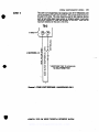
ZONE 1
a
IV 21
‘USE BRK SMOKE DETECYORS ONLY:
1400 lONKAllON
2400 PHOTOELECTRIC
24WTti PHOTO Wf125o HEAT SENSOR
414oXM
USES TERMINAL BLOCK
413oXM/513oXM
USES COLORED WIRES
ORANOE
I
I\
wmw
I+) RED/YELLOW
(A)
BROWN
I
13.ooo OHM
END OF LINE
RESISTOR
I
I
1
ZONE 1 (A) two-WIRE IBU~KE OEYECYOR HOOK-UP
(B)
(B) ALTERNATE NORNALLY CLOSED
CONRGURATION
Diagram 1. P-WIRE SMOKE DETECTOR HOOK-UP
ADEblCO’r
VISTA XM SERIES TECHNICAL
REFERENCE
MANUAL
WWW.DIYALARMFORUM.COM
22
SYSTEM
ZONES
CONFIGURATION
2 THROUGH
(ZONES)
8
These zones have a 350 milliiecond response and can be assigned to any
zone type. They can be EOLR supervised or closed circuit unsupervised, as
required (program field ‘41 determines whether or not these zones will use
the 1,000 ohm EOLR: Enter [l] in field ‘41 to disable the use of EOLR’s on
zones 2 through 8). If programmed for use with EOLR’s. both closed-circuit
and open-circuit devices can be used with the 1.000 ohm EOLR resistor in
series with the bop at the last device, as shown in A below. If the use of
EOLR’s is disabled (‘41-l), only closed-circuft devices can be used, as
shown in B below. Note that the maximum resistance per zone is 300 ohms.
T&l
m-2
Dlsgram 2A. ZONES 2-3 EOLR SUPERVISED CONFIGURATION
Dlagmm 28. ZONES 2-8 CLOSED-CIRCUIT UNSUPERVISED CONFIGURATIONS
,--
ADEMCO’r
VISTA
XM ShtXES
TECHNIGU
REFERENCE
MANUAL
WWW.DIYALARMFORUM.COM
SYSTEM CONF~GURATIGN
ZONE 9
(ZONES)
23
This zone is an unsupervised, fast response zone (5-10 milliseconds), and
can be assigned to any zone type except fire. Only closed-circuit devices can
be used in this zone. This zone should be used for fast response devices
such as fast acting glass break sensors or vibration sensors. Avoid using
mechanical magnetic or relay type contacts in this zone. Note that the
maximum resistance for this zone is 100 ohms.
TB-2
33
4140XM c
Qi
14
9
‘-RESPONSE TIME: 10 milliseconds
NO EOLR PERMITTED!
Diagram 3. ZONE 9 FAST RESPONSE - UNSUPERVISED ONLY
ADEMCO~
VISTA xbz SERIES TEcBNICAL
i&iUtENc~
MANUAL
WWW.DIYALARMFORUM.COM
24
SYSTEM
CONFIGURATION
(ZONES)
-
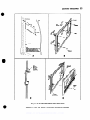
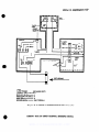
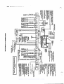
B. ZONE EXPANSION MODULE(Required
GENERAL
INFORMATION
for zones
10 through
64)
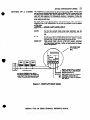
To expand the system using a P-wire Polling Loop an&or wireless devices, a
4171XT-XM dialer board, and a 4152LMB Loop Module must be installed as
shown below. (The 4171 XT-XM is factory installed in the 4140XM.)
Remove the Control’s back cover and discard. Insert three small standoffs
(supplied) into the three holes on the Control board (marked A. B & C on the
diagram), pressing each until they ‘snap’ into place. Insert the 1Spin male-tomale adapter (supplied) into the interface socket pin holes on the underside
of the Dialer board as shown.
Guide the adapter pins into the pin holes on the Control bvoard, while
aligning the standoffs with their respective holes in the Dialer board. Be sure
the adapter pins are properly entering the Control board holes, and press
down until the pins are fully seated and the standoffs “snap” into place.
Note the 8 square-shaped connector pins on’the dialer board. Position the
4152LMB board over that board so that these pins engage the mating
sockets (header) on the underside of the 4152LMB. Press the 4152LMB
down until the pins are fully seated. Secure the No. 4152LMB by means of 3
screws (supplied).
Wires from the 4208 Zone Expander, RPMs, and 4280 are connected to
Terminals 1 8 2 on the 4152LMB. For information regarding polling loop or
wireless expansion, refer to those sections which follow.
4171XT-XM
INSTALLATION
4152LMB
INSTALLATION
I
INSTALLING LOOP MOOULE
INSTAIUNG DIALER BOARD
Dlagmm 4.4152LMB INSTALLATION AND WIRING
ADEMCO’s
VISTA
XM SERIES TECHNICAL
REFERENCE
MANUAL
WWW.DIYALARMFORUM.COM
..
SYSTEbi
-
CONFIGUBATION
(ZONES)
25
C. 2-WIRE POLLING LOOP EXPANSION (ZONES
10 THROUGH
64)
To expand the system using a P-wire polling bop and remote point modules
(RPMs), a 4171XT-XM dialer board, and a 4152LMB loop module must be
installed, as de&bed in the ZONE EXPANSION MODULE section.
Any of the RPMs can be used, in any combination, to expand the system to a
maximum of 64 zones. For a complete list of available devices, see the
HARDWARE OVERVIEW section
The polling bop can be run in various ways, as shown. Choose the way that
best suits your needs, but make sure that polarity is correct throughout the
system. If polarity is reversed at any point, a Ioop short” will occur (displayed
as 197”). Calculate the total current required by completing the Polling Loop
Current Draw Worksheet found in the Summary of Connections section.
GENERAL
INFORMATION
BASIC9
HARDWIRED ZONES
Dlagmm 5A. ZONE EXPANSION USING RPM8
Diagram SB. VARIOUS POUING LOOP CONFlGURATlONS
Wire each of the RPMs In parallel to the P-wire polling loop, making sure no
more than the maximum allowable wire length is used per individual polling
bop run, as follows:
#22gauge@65o’max
#20 gauge @9w max
#18 gauge @lSOol max
#16 gauge @2400’ max
NOTE: Twisted pair recommended for all no-1 wire NCIE.
IMPORTANT:
The maximum combined polling loop run is 4000’. If
uslng shielded wire, the maximum.is 2000’. lf bnger wire
runs are needed, a 4197 Loop Extender module must m
be used.
ADEMCO’S
VISTA XM SERIES TECENICAL
REFERENCE
MANUAL
WWW.DIYALARMFORUM.COM
,
26
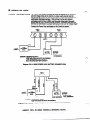
SYSTEM
4197
CONFIGURATION
LOOP
EXTENDER
(ZONES)
If longer polling bop wire runs are needed or more than MmA current is
being drawn on the polling loop, a 4197 Loop Extender Module must be
used. Diagram 6 shows typical connections. Note that power from a local
power supply is not approved for UL installation.
EnENDED
POLLING LOOP
4197 POLLING EXTrNDER POWERED PROM PANEL
VISTA
NOTECONNECT
TERMINALS 2
AND 3 AS SHOWN
CONTROL
n.
POWER SUPPLY: (CONNECT TO AN UNINTERRUPTED 12Ot!. 6OHz POWER SOURCE THAT IS ON
INPUT POLLING LOOP
EXTENOED POLLING LOOP
4197 POWERED PROM LOCAL POWER SUPPLY AND BARERY
Dlrgmm 6.4167 POWER CONNECTIONS
NOTE: Twisted pair recommended tor all normal wire runs.
CAUTfON: lf an intercom system is Being used, the polling loop wires must
be as far from the intercom wiring as possible (minimum 6’). If this spacing
cannot be achieved, shielded wire must be used. It this is not done,
interference on the Intercom system might occur. Also note that the
maximum total wire length supported is cut in half when shielded wire is used.
ADVISORY
The maximum allowable current draw on the polling loop is 64mA. Refer to
the Polling Loop Current Draw Worksheet (found in the SUMMARY OF
CONNECTIONS section) for current draws of various polling loop devices.-If
more than 64mA is being drawn, use of the 4197 provides another loop with
64mA available.
..--.
ADEMCO’s
VISTA
XM SERIES
TRCHNICAL
REFERENCE
MANUAL
WWW.DIYALARMFORUM.COM
SYSTEM CONFIGIfRAl7ON
a
SE-KING
UP A 4190WH
(ZONES)
27
The 4190WH is a O-zone (known as left and rtght zones) RPM. The lett zone
can be used tor cbsedcimult devices, with or without EOLR supervision. and
for open-circuit devices, with EOLR supervision. The left zone can also be
used wlth fast-response (10 millisecond) devices, if necessary. Follow the
chart below for cutting the correct jumpers and choosing the correct resistor
when using the left zone.
The right zone is for closed-circuit, unsupervised use only, and has a
response time of 400 milliseconds. Do not cut any jumpers or use a resistor
on this zone.
JUMPFRS
USACj&&EFT Zu
ONI Y\
RED:
WHITE:
BLUE:
NONE CUT:
Cut tar fast-response (10 millisecond).
Cut tar low current mode (reed type switches); use the
30,000 ohm resistor, provided. Must be cut if BLUE jumper is
cut.
Cut tor use with no EOLR (closed-circuit only). Doing this
automatically puts an internal 30,000 ohm resistor in series
with the zone, so the whitejumper must also be cut.
High current mode: Use the 4.700 ohm resistor, provided,
with mechanical switches in either an open-circuit or closedcircuit configuration.
EXPLODED VIEW
RIGHT LOOP: FOR N.C. SERIES
CIRCUITS ONLY. USE SEALED
(REED) CONTACTS.
LEFT LOOP: FOR N.C. CIRCUIT
(INTERNAL EOLR) OR N.C.
AND/OR N.O. CIRCUIT (UCTERNAL EOLR).
ALWAYS OBSERVE POLARITY.
ALWAYS CONNECT IN PARALLEL.
. SEE TEXT FOR WIRE GAUGE AND
WIRE LENGTH REQUIREMENTS.
l
l
Diagmm 7. 4190WH LEFT/RIGHT ZONES
ADEMCO’s
WSYA XM SERIES
TECHNICAL
REFERENCE
MANUAL
WWW.DIYALARMFORUM.COM
28
SYSTEM
SETTING
CONFIGURATION
(ZONES)
UP THE 4208
The 4208 is an 8 zone RPM which is connected directly to the polling loop.
Each zone is end-of-line-resistor supervised and can be used with either
open-circuit or closed-circuit devices. Zone numbers used with the 4208 are
pre-assigned in groups of 8 (except the first group) beginning with zone 10,
and are set via the unit%DIP switches. Note that if more than one 4208 is
used, the system limits the number of zones supported by the first group of
addresses to 7 (zones lo-16 available). If only one 4208 is used, the first
group of addresses can be expanded to 8 zones (zones lo-17 available) by
entering a 1 in program field ‘86. See the PROGRAMMING section tar
information regarding this programming option. See the PROGRAMMING
section for information regarding the use of more than one 4208.
The first two zones are DIP switch programmable for fast response (10
millisecond). Zones connected to this module are factory set for 400
millisecond response. The first six zones are high current zones for use with
mechanical sensors. The last two zones can support only low current sensors
(reed switches, etc.).
IMPORTANT!:
The 4208 does not support P-wire smoke detectors.
PR?ZFAM
SWITCH
NOTES
4700 Ohms
LOOP 21
4700 Ohms
LOOP 3
I
4700 Ohms
LOOP 4 1
4700 Ohms
-0OP 5
4700 Ohms
I
NOTES:
A. Uses both sealed (reed) and unsealed (mechanical) ContOctS.
8. Requires an external 4700 Ohm end-of-line resistor (small W watt.
YELLOW-VIOLET-RED
color bands).
C. Selectable fast or slow response (both loops as a pair).
0. Uses 1 milliamp 01 current each.
E. Uses only sealed (reed) contacts.
F. Requires en external 36.660 Ohm end-o&line resistor (large. H watt.
ORANGE-BLACK-ORANGE
color bands).
G. Uses 100 microsmps 01 current each.
H. Make certain that the maximum current lrom the control’s polling
loop is not exceeded.
1. If set for zones S-16. loop #l is lost on the 4206.
Diegmm 6. 4208 SUMMARY OF CONNECTIONS
ADEMCO’s
VISTA XU SERIES
TECHNZCAL
REFERENCE
MANUAL
WWW.DIYALARMFORUM.COM
SYSTEM CONFIGURATION
TABLE
1.
DIP SWITCH TABLES
ADEMCO’s
FOR POLLING
VISTA XM SERIES TECHNICAL
REFERENCE
(ZONES)
LOOP DEVICES
MANUAL
WWW.DIYALARMFORUM.COM
2
9
30
SYSTEM
CONFIGURATION
(ZONES,
.-\
-
0. WIRELESS ZONE EXiANSlON
(ZONES
1 THROUGH
-
63)
GENERAL
INFORMATION
To expand the system using ALERT III wireless transmitters, a 4171XT-XM
dialer board, and a 4152LMB loop module must be installed, as described in
the ZONE EXPANSION MODULE section, and either one or two 4280s (or
4280-8% if only 8 wireless zones are required) must be connected to the
polling loop. Note that the 4280 draws 40mA current. If two receivers are
used, power for the second receiver should be taken from the auxiliary power
connection on the main Control.
NOTE: Unless stated otherwise, references to the 4280 Receiver represent
the 4280 andlor 4280-8 Receivers.
The 4280 RF receiver is a component of the VISTA XM system which
recognizes alarms, status messages and keypad control messages from
ALERT Ill transmitters at 345MHz (U.S.A.). These messages are processed
and relayed to the VISTA XM control panel via a P-wire polling loop. Using a
4280 allows expansion of up to 83 RF zones, plus a wireless keypad (5727).
RANGE
The 4280 RF receiver can receive signals from wifeless transmitters within a
nominal range of 200 feet. This gives you greater expandability in installations
where hard wire might not be feasible.
SUPERVISION
Each transmitter (except 5701 and 5727) is supervfsed by a check-in signal
that is sent to the receiver at 70-90 minute intervals. If at least one Check-in is
not received from a transmitter within a programmed interval, the keypad will
display the transmitter number and ‘CHECK’ will be displayed. See the
section under PROGRAMMING RF OPTIONS. 1’31, for this selection.
Each transmitter (including 5701 and 5727) is also supervised for low battery
conditions, and will transmit a low battery signal to the 4280 when the battery
has approximately 30 days of life remaining. See PROGRAMMING RF
OPTIONS. 1’28, for LOW BATTERY AUDIBLE ANNUNCIATION selection.
NOTE: After replacing a low or dead battery, activate the transmitter and enter
the security code + OFF to clear its memory of the “Low Battev signal.
The 4280 itself is also supervised three ways:
1. If the cover of the 4280 is removed, an ALARM or TROUBLE will be
displayed depending upon the response programmed in fields 1’08 and
1’09.
2. If the connection is broken between the 4280 and the control panel, an
ALARM or -TROUBLE will be displayed depending on the response
programmed in programming fields 1’08 l? 1’09. This response is usually
that of a DAY/NIGHT or 24 hour type.
3. If, within a programmed interval of time, the 4280 does not hear from any
of its transmitters, an ALARM or TROUBLE will be displayed depending
on the response programmed in fields 1’08 8 1’09. The interval is
programmed in 1’30.
The 4280 responds only to transmitters with the same house ID (DIP switch
programmable
from 01-31). This prevents system interference from
transmitters in other nearby systems. To make sure you do not choose a
House ID that is in use nearby, put the system in the Sniffer Mode, which is
descrfbed later in this section.
HOUSE
IDENTIFICATION
ADEMCO’s
VISTA
XM
SERIES
TECHNICAL
REFERENCE
MANUAL
WWW.DIYALARMFORUM.COM
,,-.
-
;-.
SYSTEM CONFIGURATtON
(ZONES)
31
TRANSMITTER
IDENTIFICATION
Each transmitter has its wn unique ID number (Zone #), which is DIP switch
programmable in each unit. Whenever a transmission takes place, either for
an alarm, fault, check-in or lw battery, this ID number is sent along with the
message to the 4280 which, in turn, relays this information to the control
panel, which displays the condition and zone number on the keypad. See
the DIP switch selection chart at the end of this section, for individual
transmitter settings.
SNIFFER
To check for house fDs being used in nearby systems, set the DIP switches in
the 4280 for a House ID of ‘00’ (all switches up), then enter your ‘Installer
Code’ + [#I + (21. The 4280 will now ‘sniff” out any House IDS in the area and
display them. Keeping the 4280 in this mode for about 2 hours will give a
good indication of the house ID’s being used. To exit the Sniffer Mode,
simply key your installer code + OFF, then set your house ID to one not
displayed in the Sniffer Mode’.
MODE
To check that all transmitters have been set for the proper house ID, set the
4280 to the proper house ID and enter the Installer code + [#] + 131. All
transmitter ID numbers that have the house ID set for the 4280 will be
displayed when each transmitter number checks in (up to 2 hours). A faster
way to do this is to faulf each transmitter, which causes a transmission to be
sent to the 4280. Check that the ID number is displayed when the transmitter
is faulted.
BUILT-IN *‘GO/NO GO”
TEST MODE
(Patented)
This mode helps determine the best location for each transmitter and is
activated by putting the system in the TEST mode and removing the 4280%
cover. The receiver’s sensitivity is reduced by half. Once transmitters are
placed in their desired locations and the approximate length of wire to be run
to sensors is connected to the transmittefs screw terminals, open circuit each
transmitter. Do no? conduct this test with your hand wrapped around the
transmitter.
4280
SET-UP
ERRORS
If a single 4280 is used, the keypad will beep three times to indicate signal
reception. If two 4280s are used, the keypad will beep once if the first 4280
received the signal, twice if the second 4280 received the signal and three
tfmes if both receivers heard the signal (which is desirable for redundant
configurations).
If the keypad does not beep, reorient or move the transmitter to another
location.
To exit this mode, replace the 4280’s cover, then enter the installer code and
press OFF. Note that the Receiver’s sensitivity is fully restored when the
wver is replaced.
All RF zones must be designated as such in their respective programming
fields. tf using a 4280-8, on/y up to 8 zones can be enabled as RF zones. If
more than 8 zones are enabled, the message ‘SET-UP ERROR’
(5130XMI5137) or ‘E8’ (4130XMI4137) will be displayed.
WWW.DIYALARMFORUM.COM
32
SYSTEM
CONFIGURATION
(ZONES)
.--.
ADVISORIES
Do not place transmitters on or near metal objects. This will decrease
range ancVor block transmissions.
2. Place the 4280 in a high, centrally located area for best reception. Do not
place receiver on or near metal objects.
3. The 4280 receiver nust be at least 10 feet from the Control panel or any
remote consoles to avoid interference from their microprocessor.
4. When connecting a door/window contact to a 5711, 5711WM. or 5715
transmitter, avoid a wire length of 20-24 inches. This particular length
decreases range. A shorter or longer length has no effect.
WIRELESS
ZONE TYPES
Each RF zone can be programmed to respond as any zone type such as
ENTRY/EXIT, INTERIOR, PERIMETER, etc. (see the section under ZONE
TYPES for a complete explanation of each zone type). Desired alarm
responses can be broken down as follows:
1.
JRANSMTTTFRS
Wf
ZONf NPF
Entry/Exit Burg
Perimeter Burg
Interior Burg
i through 63
1 through 63
1 through 63
32 through 47 (5775)
1 through 63 ‘(5715)
48 through 55 * (5706)
1 through 63’
62 or 63 “** (5701)
1 through 63
1 through 63
l
l
l
l
Are
l
24 Hour Panic (silent or audible)
Day/Night Burglary
24 Hour Auxiliary
NOTES:
Transmitters set for an ID of 32 through 47 will have a 3 minute bckout between transmissions.
..
Transmitter ID’s 48 through 55 have highest signal priority.
...
Transmitter ID’s 62 and 63 are unsupervised to allow removal of the
5701 otf premises - signal priority is lower than that of fire, but higher
than burglary.
l
l
l
ADEMCO’s
VISTA
XM
SERIES
TECHNICAL
REFERENCE
MANUAL
WWW.DIYALARMFORUM.COM
.-..
SYSTEM CONFIGURATION
SINGLE
RECEIVER
RECEIVER CONFIGURATION
For additional security, some installations might warrant a redundant
configuration. This means that 2 receivers, connected to the same P-wire
polling loop, are used and set to the same house ID. Each of these receivers
listens to all of the transmitters on the job, but If one receiver happens to fail
or is sabotaged, or a path from one or more transmitters is inadvertently
blocked by a metal object, the other one will still be there to detect aiarms.
and fautts, and to supervise the transmitters. Roth 4280s (or 4280-8s) are
fully supervised so that ff one does fail or is deliberately sabotaged, you’ll
know about it.
cI----_
-.
NH
Diagram 11. TWO WIRELESS RECEIVERS REDUNDANT
ADEMCO’s
33
A single 4280 RF receiver can uniquely identify up to 64 transmitters within a
nominal 200’ range, without the work of hard-wiring a brge premises, and is
suitabfe for many instaiiatiins.
Diagmm 10. SlNGLE.WlRELESS
USING TWO
RECEIVERS
FOR
REDUNDANCY
CWNESJ
VISTA iSA4 SERIES TECIiNKAL
CONFIGURATION
REFERENCE
MANUAL
WWW.DIYALARMFORUM.COM
34
SYSTEM
CONFXCVRATXON
USING TWO
RECEIVERS
TO
INCREASE
COVERAGE
(ZONES)
For installations where the area to be protected goes well beyond the 200
range of the system, or the building configuration preventsgetting the rated
range in ail paths to transmitters, a second receiver can be installed. The first
4280 is bcated at one end of the premises and the second 4280 at the other
with both 4280s connected to the same P-wire polling loop.
AREA 12
Dlsgmm 12. TWO WIRELESS RECEIVERS TO INCREASE COVERAGE
ADVISORIES
1. if dual 4280s or 4280-8s are used:
A. Both must be at least 10 feet from each other, as well as from the
vista XM Control panel and remote consoles.
B. One of the 4280s or 4286-8s must be powered from Aux. power
(see SPECIFICATIONS).
C. The house IDS must be the same.
0. Using two Receivers &es not increase the number of transmitters
the system can support (62 transmitters, plus a wireless keypad).
2. Follow the chart below for max. polling loop runs:
V22 gauge @65fY max
320 gauge @95V max
‘#I8 gauge @lSOO’ max
‘#16 gauge @ 2400’ max
Note:
Twisted pair recommended for ail normal runs.
IMPORTANT:
The maximum combined polling loop run is 4000’. If using
shielded wire, the maximum is 2000’.
CAUTION: if an intercom system is being used, the polling loop wires must
be as far from the intercom wiring as possible (minimum 6’). if this spacing
cannot be accomplished. shielded wire must be used. If this is not done,
interference on the intercom system might occur! Also note that the
maximum total wire supported is cut in hall when shielded wire is used.
ADEXCO’s
VISTA
XM SERIES
TECHNXCAL
REFERENCE
MANUAL
WWW.DIYALARMFORUM.COM
,-.
SYSTEM CONFIGURATION
TABLE
2.
DIP SWITCH TABLES
FOR WIRELESS
DEVICES
HOUSE I.D. SWITCH
SETTING FOR ALL
WIRELESS DEVICES.
ADEMCO’s
VISTA XM SERIES TECHNICAL
REFERENCE
MANUAL
WWW.DIYALARMFORUM.COM
(ZONES)
35
36
SYSTEM
CONFIGURATION
-
(ZONES)
E. ZONE EXPANSION COMBINATIONS
INTRODUCTION
-
One of the VISTA system’s strengths is flexibility. VISTA permits the use of
homerun hard-wire, polling loop and wireless technologies
in any
combination.. The first 9 zones can be efther ail hard-wired. ail wireless (using
a 4280 RF receiver with ALERT iii transmitters), or a combination of both
technologies. Zones 10 through 64 can use either ail polling ioop devices, ail
wireless (RF) devices,or a combination of both technologies.
The selecting of wireless or polling loop zones is programmed in fields 1’18
to 1’25. To enable a zone as a wireless (RF) zone simply enter a “1’ in the
tocation for that zone, as shown:
Ex: SELECT RF (ZONES 1-8)
12345678
01110001
In the above example, zones 2,3,4, and 8 are programmed to be wireless
(RF) zones; zones 1,s. 6 and 7 are hard-wired.
WIRELESS
PERIPHERALS
SMOKE
4280
OR
4280-8
RF
RECEIVER
a
41520
LM@
I
a
*
RPM DEVICES
&
n POLLtNG LOOP
.
f
RPM
RPM
\
BASIC 9 HARD-WIRED ZONES
b
b
COMBINATION CONFIGURATION:
USING HARDWIRE, P-WIRE POLLING LOOP
AND WIRELESS TECHNOLOGIES
Diagram 13. ZONE EXPANSION COMBINATION CONFIGURATIONS
1. Any zone from l-63 can be designated as an RF zone.
2. Be careful when designating RF zones. If you want a zone to be either
hard-wired or on the polling loop, but accidentally enable it as RF, the
system will ignore that zone. RF enable overrides hard-wire!
ADVISORIES
,-..
ADEMCO’s
VISTA Xh4 SERIES
TECHNICAL
REFERENCE
MANUAL
WWW.DIYALARMFORUM.COM
SECTXON V
SYSTEM
37
SECTION V
CONFIGURATION
(PERIPHERALS)
-
GEP;IERAL
A. REMOTE CONSOLES Both the 4130XM and the 5130XM supply up to 28OmA (2OOmA for UL
certificated installations) of auxiliary power for remote consoles and/or other
auxiliary devices such as motion detectors or 4-wire smoke detectors. The
4140XM supplies up to 700mA for non-UL usage and up to 400mA for UL
applications. You must keep this in mind when adding remote consoles so
you don’t “overdraw’ current from the panel. This would result in a battery
which is never fully charged, or possibly a blown auxiliary power fuse.
In the event you need more than the allowed number of remote consoles,
you can use a second #1350 power pack to power up to 7 extra 4137s or up
to 4 extra 5137s. Instead of using the panel’s auxiliary power connection to
the red and black console lead, connect the Positive (+) terminal of the 1350
to the blue console lead, and the Negative (-) to the black lead. As long as AC
power is present, these extra consoles are active. If AC is lost , the system’s
back-up battery will take over and only the consoles powered from auxiliary
power will be active.
NOTE:
lf using a 4140XM, make sure you power at least 1 remote console
from auxiliary power, otherwise there would be no means of controlling the
panel during an AC loss.
- For use with the 4130XM. 4140XM or 5130XM Controls
-6OmAcurrentdraw
- Power up to 4 consoles from the 4130XM and 5130XM (non-UL)
- Power up to 7 consoles from the 4140XM.(nonUL)
4137
l
5137
- For use wlth the 414OXM or 5130XM Controls
-8OmAcurrentdrawnormal
- 90 mA current draw wlth backlighting on
- Power up to 7 consoles
Diagram 14. REMOTE CONSOLE HOOK-UP
ADEMCO’s
VISTA XM SERIES TRCIiNlCAL
REFERENCE
WWW.DIYALARMFORUM.COM
A¶Ah’UAL
se;
38
--SYSrEM
CONFIGURATION
(PERIPHERALS)
--k3*--x4%-
.i
‘&
’;
7 B. EXTERNAL S-OUNDEFS :
~-i.
. i
._
4140XM
-.
_ --~.-.I
The 4140XM is housed in a metal cabinet and contains a built-in relay, rated at
2.8 pps. The oirtputof..this reliy is a positive (+) trigger from terminal 8 on
TB2, tith the negative from TB2-15. Up to two 702s can be used, wired in
series as shown in A; up to two 719s in parallel as shown in B: ;
‘USECONFIGURATIQN(A) OR (8)
SEPAAATELY...NOT
TOGETHER!
I.
a.
(-1
(B)
‘.
(+I %N
t-1
(+) :;&J
_
IN “PARALLEL”
.DiegmIh 15. SOUNDER OPTIONS FOR 4140~.k CbkiROL
-
....
-.*.
-.
-5
/iDEMCOis
V&A
-“ihi
SE&
‘TE&NKAL
<:
RhERENCE
MANUAL
WWW.DIYALARMFORUM.COM
SYSTEM CONFIGURATtON
(PERIPEERALS)
39
The 4130XM15130XM self-contained Controls have an external sounder
output of lOOmA, (negative-going (-) trigger) from the brown lead. The
continuous positive (+) is taken from the red/black lead. From this output you
could use up to two 740 High Intensity BOUnd8rS, wired in parallel, or one
Amseco Motor Bell, ABB1031, or up to eight indoor Pier0 SoUnd8K. BRK
PA4OOB in parallel, as shown:
4130XM/5130XM
FROM 513OXM OR
413oXM CONTROL
(8)
UPT02
0 OR (D)
740s
wo0mEacoyBlNA1IoNs1 740 IN PARALLEL WITH 3 BRK PA400
Dlagram 16. SOUNDER OPTIONS FOR 5130XM OR 413OXMCONTROLS
4148
RELAY
MODULE
Other sounders, such as the 702 and 719 S8kontained sirens can be used
with the 4130XM/5130XM, but the addition of the 4148 Relay Module is
necessary because these sirens (or equivalent) draw more than the allowable
1OOmAof current. Connect the 4149 module, to the control, as shown:
.
?
VISTA
CONTROL
-1TO SOUNDER
+
BROWN
t-r TRlGaER
TRIGGER
12VDC
3AFASTBLOFUSE
POWERFUSE
4 AH MIN
BATTERY
m
4148 RELAY MODULE l
VISTA XM SERIES
TECHNICAL
REFERENCE
l TIKI 4148 IS NOT UL
APPROVED FOR USE
THE 413OXMI!33OXM.
Dlagmm 17. 4148 RELAY MODULE
ADEMCO’s
NOTE:THE 4148
MODULEMUSTBE
LOCATU) As CLOSE
As POSSIBLETO
BATTERY
MANUAL
WWW.DIYALARMFORUM.COM
WnH
40
702
SYSTEM
CONFIGURATION
SIREN
(PERIPHERALS)
Up to two 702s can be used, wired in series. as shown:
3A FAST BLO
TWO WO2 SIRENS IN “SERIES” ON A 413OXY OR
SlSOXM CONTROL USING A 84148 RELAY MODULE
-
TO VISTA STANDBY 6AlTERY
(12VMOAH MINIMUM)
Y
I
A
Diagram 18. TWO 702 SIRENS IN SERIES
719
SIREN
UP t0 two 719s can be used,. wired in parallel, as s,hown:
TO VISTA STANDBY BATTERY (12VII.O
..-\.
.
Diagram 18. TWO 719 SIRENS IN PARALLEL
1. Going beyond the above mentioned limits will result in a blown auxiliary
power or relay tuse.
2. The 4148 relay is rated at 2.8 Amps @ 28 VDC max. If sounders or drivers
other than the ones mentioned above are used, make sure the maximum
current draw does not exceed 2.8 Amps.
CAUTION: These sounders are polarized (+) and (-)! If polarity is reversed,
the sounder will not work!
:--.
ADEMCO’s
VISTA
XM SERIES
TECHNICAL
REFERENCE
MANUAL
WWW.DIYALARMFORUM.COM
:
STSTEbi CONFIGURATION
-
C. SMOKE DETECTOR CONFIGURATIONS
ZONE 1
(PERIPIH3bU.S~
41
-
When programmed as an EOLR supervised FIRE zone (type 09 in program
field ‘02) up to three O-wire smoke detectors can be used. Recommended
are the BRK1400 ionization detector, 2400 Photoelectric smoke detector,
and the 24OOTH Photoelectric smoke detector with 135°F heat sensor.
FOLLOW INSTRUCTIONS FOR INDIYIDUAL SMOKE DlTEClDRS
AND WIRING.
*USE BAK MODEL 1400.2400. OR 240Vt.H ONLYI
FOR PROPER INSTAUATION
l
Diagram 20. ZONE 1 EOLR SUPERVISED FOR O-WIRESMOKE DETECTORS
ADVISORY
ZONES
If the EOLR is not at the end of the loop, the zone is not fully supervised. The
system will not respond to an open circuit within the zone.
2 THROUGH
8
These zones can suppart as many 4-wire Smoke detectors as can be
powered, when programmed as a FIRE zone, type 09, in program field ‘02.
There are only two requirements: (1) The zones must be configured for
EOLR supervision, and (2) A normally-closed, momentary Switch must be
Installed in series with the power to the detectors in order to allow reset of the
smoke detectors after an alarm. The detectors must be wired in parallel, with
the EOLR at the last detector, for full supervision. as shown:
ANY ZONE.2THRUS
.
TB2
USE OF RELAY
SMOKE
DETECTORS
I
II
II
lmo OHM
END OF LINE
RESISTOR
FOLLOW INSTRUCTIONS FOR INDIVIDUAL SUDKE DEMXDRS
FDR CtRtXJll AND PDWER
FOR PRDPER INSYALLATIDN AND WIRING
D&gram 21. ZONES 2-8 EOLR SUPERVISED FOR CWIRE SMOKE DETECTORS
ADEMCO’s
VISTA XM SERIES TECIYNICAL
REFERENCE
WWW.DIYALARMFORUM.COM
MANUAL
42
SYSTEM
CONFIGURATION
(PERIPHERALS)
,-,
POLLING LOOP
SMOKE DETECTORS
(4192S0,
4192SDT
OR 4192CP)
Can be added to the g-wire Polling Loop via the 4152LME loop module, on
zones 10 through 84 (as programmed in fields ‘05, 1’02, 1’03, 1’04 and
l’OS).These
detectors
have a built-in RPM which is DIP switch
programmable. They are wired in parallel to the polling loop, and do not need>
auxiliary power or a separate reset switch. The polling bDp provides power
and reset signals to the detectors,as well as alarm and trouble signals from
the detectors.
4152LMB
POLLING
LOOP
I
6.WIRE
FOUlNO
LOOP
UIOKE
DEl’SCTOR6
Diagram 22. P-WIRE POLLING LOOP SMOKE DETECTORS
ADVISORIES
1. The maximum polling kop runs are as follows:
#I22 gauge @ 650’ max.
#20 gauge @ 950’ max.
818 gauge @ 1500’ max.
#16 gauge @ 2400’ max.
IMPORTANT!:
The maximum combined polling loop run is 4000’. If
using shielded wire, the max. is 2000’.
2. Twisted pair is recommended lor all normal runs, but ii an intercom system
exists, or is being planned, you must keep the poking loop at least 8’
from the Intercom wiring, or use shielded wire. If not, you might
experience intercom interterence.
l
l
l
l
WIRELESS
SMOKE
DETECTORS
(5706)
Can be used on zones 48 through 55 as long as that zone is enabled for RF
usage in program fields 1’23 and/or 1’24, and are programmed as FIRE
zones, type 09, in fields 1’03 an&or 1’04. These detectors have buiit-in
transmitters and are powered from a single 9 volt battery. A 4280 RF receiver
must be connected to the a-wire polling loop driven by the 4152LMB loop
module. These transmitter/detectors are DIP switch programmable and are
fully supervised for bw battery and check-in.
MODULE
4260 RF RECEIVER
+
*
e
(+I(-)
‘UP TO 0 #Nemo
oElFcTonscAN
BEUSLD.
QQOO
POLLING LOOP f-1
I
B%iE
-A
a
POLLING LOOP (-1
63
f---Y
5706
Diagram 23. RF SMOKE DETECTORS SMoKE
ADEMCO’s
VISTA
XM
SERIES
TECHNICAL
REFERENCE
MANUAL
WWW.DIYALARMFORUM.COM
SYSTEM CONFIGURATION
-
43
0. PASSIVE INFRARED MOTION DETECTORS -
GENERAL
INFORMATION
POLLING
(4196)
(PERIPHERALS)
Select a mounting site with the following notes in mind: Best coverage will be
obtained if the mounting site is selected such that the likely direction of
intruder motion is across the pattern of protection.
Avoid locating the unit where central heating radiators, flames or heating
outlet ducts are within the protective zones.
Avoid locating the unit in direct sunlight or directly above strong sources of
heat.
Avoid locating the unit on unstable surfaces.
Avoid running alarm wiring close to heavy duty electrical cables.
Make wire connections as shown:
LOOP PIR
The 4196 is a quad element passive infrared detector with a buitl-in RPM that
is connected directly to the- polling loop. It provides up to 40 feet of
protection, using a wide angle mirror, or up to 70 feet of corridor protection
using the long range mirror (both mirrors are provided with the unit). A right
zone is available for use with closed-circuit devices and can be programmed
for a different zone type than the PIR. The 4196 can be flat wall mounted or
comer mounted, using the mounting plate provided. Programming of the
unit’s address ID is accomplished via the units DIP switches (see Table 1 in
the preceding section). Refer to the instructions accompanying the 4196 for
patterns of coverage and procedures for changing mirrors.
4196 PIR W/BUILT-IN
RPM
LiiFEl
WIDE ANGLE
MIRROR
LONG RANGE
MIRROR
(SET FOR ID NO. 8)
THIS RIGHT LOOP IS ALWAYS
NORMALLY CLOSED, UNSUPERVISED!
DO NOT USE EOLR!
Diagram 24. 4196 POLLING LOOP PIR
ADEbfCO’s
VISTA XM SERIES TECtjlNICAL
REFERENCE
WWW.DIYALARMFORUM.COM
MANUAL
44
SYSTEM
CONF~GURATXON
fPERIPIfi?RALS)
.A.
POLLING
(4275)
LOOP
PIR
The 4275 is a dual element passive infrared detector, with a built-in RPM, that
is connected directly to the P-wire polling loop. It provides up to 45’ of
protection, using the wide angle mirror, or up to 70’ of narrow (corridor or
curtain) protection, using the long range mirror (both mirrors are provided).
The PIR can be mounted flat on the wall or comer mounted, with the
mounting plate provided. Programming is done via the DIP switches (see
Table 1 in the preceding section). Refer to the instructions accompanying the
4275 for patterns of coverage and procedures for changing mirrors.
Connect as shown:
.-
Dlrgmm 25. 4275 POLLING LOOP PIR
WIRELESS
(5775)
PIR
The 5775 is a battery operated, wireless, dual element passive infrared
motion detector and provides wide angle protection with a range of up to 35’.
The PIR features a pulse count option and can be mounted flat on the wall or
corner mounted. Programming of house ID, transmitter ID and pulse count
option is done via the unit’s DIP switch. Note that there is a 3 minute delay
between transmissions to preserve battery life. Refer to the instructions
accompanying the 5775 for additional details.
OFF ON
Dtagmm 26. 5775 WIRELESS PIR
ADEMCO’s
VISTA X-M SERIES
TECHNICAL
REFERENCE
MANUAL
WWW.DIYALARMFORUM.COM
SYSTEM CONFIGURATION
4171 XT-XM/4171
INSTALLATION
(PERIPBERAU
4s
E. PHONE LINE INTERFACE The 4171XT-XM is factory installed in the 4140XM Control. For the
4130XM/5130XM Controls, connect the 4171 XT-XM or 4171XM as shown
below. Note that If any zone expansion is being used, the Dialer board is
already installed (see ZONE EXPANSION section).
XM
DIGITAL
coMuuwIcAlIoN
INTERFACE
13CIN INTERFACE
coNWEclOn
IAo*CIER
BOARD
/
e
PiNS INSERTED FAOU
BELOW1
I3FIN YALE.16
NALE ADAPTER
\I
\
QwlyUNlCAllON
INlERFACE
PIN W)LES
Diagram 27. INSTALLING THE 4171XT-XM DIALER TO THE 413OXW5130XMCONTROLS
ADEMCO’s
VISTA XiU SERIES TECXNICAL
REFERENCE
MANUAL
WWW.DIYALARMFORUM.COM
46
SYSTEbf
CONFIGURATXON
(PERIPHERALS)
n
4171 XT-XMI4171
TERMINAL
DESIGNATIONS
XM
Terminal 1.
This is a programmable outm (See 1’46). it can be used as a
ground start output with the 675 Ground Start Module, as an
output to produce console audible warnings on a remote
sounder (ex: No. 70612), or as an open/close trigger for use
wfth other communications media.
NOTES:
The 675 is not UL listed.
Only one of the above options can be chosen.
ff either GROUND START, or CONSOLE AUDIBLE is
chosen, Auxiliary Voltage Trigger pin 4 may not be used.
l
l
l
Terminal
Terminal
Terminal
Terminal
Connect
2.
INCOMING PHONE LINE (Tip)
3.
INCOWlING PHONE LINE (RING).
4.
LOCAL HANDSETS (RING).
5.
LOCAL HANDSETS (TIP).
the green flying lead to a proper earth ground.
WARNING:
To prevent the risk of shock, disconnect phone lines at telco
jack before servicing the unit.
INCOMING
TELCO LINES
INCOMING “TIP”
1:’
,
,
,
z
0
,
A
,-..--.,
,
T
-,
,
USE RJ31X
FCORD NO.
MO-366.
/
lOl@l@lO
w
\
\
/
/
i
-
PHONE LINE
CONNECTOR BLOCK
BLACK
‘~‘~*ORANGE
LOCAL PHONES
6 (-) AUX POWER (TB2-13 OR RED/BL .ACK)
JUMPER
MUST BE CUT!
Diagram 26. PHONE LINE AND GROUND START CONNECTIONS
ADEbfCO’s
VISTA
XM SERIES
TECHNICAL
REFERENCE
MANUAL
WWW.DIYALARMFORUM.COM
SYSTEM CONFIGURATION
F. AUX. VOLTAGE TRIGGER OUTPUTS -
-
PIN
47
(PERIPHERALS)
Pin 1: Fire
Pin 2: Panic
Pin 3: Burglary
Pin 4: Open/Close (refer to ‘Phone Line Interface’)
Pin 5: Ground Terminal 1
IMPORTANT!:
The 4171TR Trigger cable must be used for connection to
these outputs.
tf the Keyswitch arming is enabled in field ‘15, then pin 1 is used for
NOTE:
the ARMED LED and pin 2 is used for the READY LED. Voltage
triggers are reset when the system is disarmed (Code + OFF) or
after the timeout interval.
Note that the 16 second Dialer delay (if programmed in field ‘88)
does not affect voltage triggers.
These triggers are atways
activated instantly.
CONNECTIONS
PHONE LINE
CONNECT GREEN
WIRE TO EARTH GROUND
(4171XT-XM
l
l
l
eoe
l
ONLY)
e
\
\ -/
y----
‘EXPLODED
VIEW
1
VOLTAGE
BLACK tGROlJND1
TRIGGERS
NOfE: IF KEYSWITCH
OPTION IS SELECTED.
AUXILIARY ALARM OUTPUT
TRIGGERS ARE NOT AVAILABLE.
GROUND
(-1
oPEN/cLosE(+)5voLTso\mAolJTPuToN~
-(ARMED
BURGLARY/AUDIBLE
PANIC/AUXILIARY
(READY LED) SILENT
PANIC/DURESS
1 (+) 5 VOLTS @ ImA
OLlTPUT ON ALARM’
\
I
LED)-FIRE
‘IF HIGHER CURRENT OUTPUT
NECESSARY. USE 685-12
SWITCHING MODULE
Diagram 29.4171XT AUXILIARY VOLTAGE TRIGGERS
ADEMCO’s
VISTA XM SERIES
TECHNXCAL
REFERENCE
MANUAL
WWW.DIYALARMFORUM.COM
IS
48
SYSTEM
CONFIGVRATXON
-
(PERIPRERALS)
.-.
G. REMOTE KEYSWITCH OPERATION & WIRING -
ADVISORY
If the keyswftch option is selected (field ‘15) the alarm trigger outputs are
disabled.
An optional Remote Keyswttch, can be used for remote arming and disarming
of the system. If used, and programmed by the installer (‘15=1), a normallyopen momentary switch is connected across a 1000 Ohm resistor on zone 7
of the control panel (Zone 7 must be given up as a protection zone but must
still be assigned a zone type). A momentary short across this zone will arm the
system in the .AWAY’ mode. If the short is held for more than 3 seconds, the
system will arm in the -STAY mode. (All zones designated as zone types 4 or
10 will be automatically bypassed). After the system has been armed, the
next time zone 7 is shorted, the system will disarm.
An optional closed-circuit tamper switch (model 112) can be wired in series
with zone 7. so that, if the switchplate is removed from the wall, the tamper will
open, disabling keyswitch operation until the system is next disarmed from
the console.
NOTES:
1. When keyswitch is selected, a 1000 ohm resistor must be used
regardless of whether.or not zones 2-8 are selected to use end of line
resistors.
2. Only one keyswitch with LEDs can be supported by the system’s power
supply. If more than one keyswitch is to be used, a 688-12 switching
module must be used to boost the signals used to drive the LEDs.
LED indications are defined as follows:
.’-
-.
DY
DISARMED & READY
ARMED AWAY
:-.
Diagrem 300.KEYSWITCH WIRING
ADEMCO’r
VISTA X&i SERIES
TECHNICAL
REFERENCE
MANUAL
WWW.DIYALARMFORUM.COM
SECTION VI
49
SECTION VI
MOUNTING PROCEDURES
-
A. MOUNTING THE 4140XM CABINET Using two screws, mount the 4140XM cabinet to a wall. If mounting to
sheetrock or concrete, anchors should also be used. wire connections can
now be made to the terminal strips.
-
B. MOUNTING THE 4130XM6130XM CONTROLS & 413715137 REMOTE CONSOLES
Note that field wiring to these wntrvlsIwnsoles must be completed before the wnttvWwnsoles can be mounted.
TWO
There are two methods of mounting consoles - Surface Mounting and Flush
Mounting. If a ‘rough-in’ ring (4133) has been installed in the wall in a new
construction application, only the flush mounting method k applicable.
Note : The four mounting tabs on the right-hand side of the 4133 rough-in
ring must be broken off before flush mounting can be implemented.
METHODS
SELECTING
SURFACE
SITES
Proper selection of mounting location and height is important for optimum
viewabifity of the LCD display on the console. A bcatfon in which lighting k
dire&y above the console should be avoided, since this can shadow the
dkptay. For optimum viewing, the console should also be mounted so that
the display k slightly below eye level to ensure that the system’s users will
look down at the display. For Alpha Console users, refer to the VIEWING
ANGLE ADJUSTMENT paragraph later in this section for instructions for
adjusting theviewing angle of the LCD.
MOUNTING
1. Use the template provided (on a separate sheet) to mark the posltiins on
2.
3.
4.
5.
6.
7.
ADEMCO’s
the wall for the screw mounting holes and the cutout for the interface
wiring. Use wall anchors for the screws and make the cut-out in the wall no
larger than indicated on the template. DO NOT use a Xerox copy of the
tenplate. as it will increase in size by about 1O?h.
Pull the interface wiring in the wall through the cut-out.
Remove the console’s back cover. The securing screw at the front of the
wnsole must be removed to release the back cover (see Diagram 31 for
scrqw focatiin).
Pass the interface wiring through.the opening in the back cover and
through ttre 4143 Expansion Ring (lf used), then mount the back cover
to the wall surface wlth screws. See Diagram 31.
Splice the interface wiring to the console wires (or to the wires on the
interface connector supplied wfth 4137s). A wiring diagram k provided in
the SYSTEM CONFIGURATION (PERIPHERALS) section. Insulated
solderless wire splices (eg. 311) may be used for spfiiing. Check wire
connections carefully before splicing.
Attacf’r the main tidy of the console to the wall-mounted bar& cover. The
console is prop&y attached when ff snaps into pface. Use the securing
screw (previously removed) to secure the console to the back oover (see
Diagram 31 for location of screw hole), then Insert the small name plate
supplied into the recessed opening to cover the screw head (see
Diagram 33).
See Diagram 31 B for mercantile/industrfal mounting wfth metal cabinet.
VISTA XM SERIES TECHNICAL
REFERENCE
MANUAL
WWW.DIYALARMFORUM.COM
50
SPkea
MOVNTXNG
PROCEDURES
tointwlsce winng
in the wall
=A
---..
Plug-inWiring Hamess Mth 18
Pm-SmPPed leads (stanoam)
No.4141-15 tts)a414l-m(m)w
Notas:
HanmssGaenwns plug
d!feceyml0 ll?s ConlfOl
l
For this type of mounting the battery
back-up power will be supplied from a
remote location. unless the installer
can:
- cut a small hole in the wall for a
No. 4132 Battery Back Box
OR
- utilize a triple gang electrical box in
the wall behind the unit to hold the
battery
OR
- mount No. 4132 Battery Back Box to an
inside wall of a closet behind the
control.
l The No. 4144 Terminal Board plugs
directly into the back of the control and
will also fit inside the Expansion Ring.
/
No. 4144 Plug-in Terminal
Boardfor localfieldwillng
termination point
Control
/Back cover ot VISTA
that IS mounted to the wall
Applications:
\
l
\
L=
a
l
VISTA Control wlh No.
4171 XM or XT-XM Digital
Communlcatfon Interface
1’
I I
Plaster wire lath construction walls
Don’t want to cut large hole in wall
No. 4143 Expansion Ring
for surface mounting with
Diir boafd instatled.
Ofient as shown.
Diagram 31A. SURFACE MOUNT INSTALLATIONS - PROFESSIONAL OFFICE/RESIDENTIAL
Notes:
l The No. 4134 Surface Mount Metal
\
Cabinet is available in tow sizes; an 6”
x 8’ x 2” version (No. 4134-67 and a
larger 12” x 12’ x 3. version (NO.
4134-l 5-) that can hold various
modules in addition to the battery.
Also available is the 4134-l 2” (12 x 12
x 3) with 4146 relay module for use
with the 702 or 719 siren.
No 4134-S Metal Surtace Mount Cabinet
Knockouts for the interface wiring have
also been provided on the rear and
sides of the cabinet.
l
\
wlrlaowispmvieeafof
mounting the VISTA
Control andCommunciatof
on the trrmt ot the unit
Applications:
l
l
‘TenntilRr@s(tihm
wrap push-in wiring) are
omwaaafoffietawinna
J
I
when using lhe larger No. 4134-l 5 C&met. there is
&so mom tot a No. 675 Gtomt San Module. No
659EN Tew Lme Faull Mamor. No. 4208 Zone
\
Battery sRs inscte cabinet
Concrete, Brick or Cement/Cinder
Block wall construction
Wherever else keypad is normally
mounted on cabinet
nm4130XM85130XMan3
ULmercemite
listed. For UL mercantile jobs use me
414oATx.
“Not Listed
Expanderand/or other modules.
Diagram 316. SURFACE MOUNTING - FOR MERCANTILE/INDUSTRIAL
INSTALLATIONS (WITH 4134-8 METAL CABINET)
ADEMCO’s
VISTA XM SERIES TECHNICAL
REFERENCE
MANUAL
WWW.DIYALARMFORUM.COM
,.-.-
bfOUNTING
PROCRDURES
!i 1
1. Mount the Control as !ollows. insert securing screw (previously
removed)
in screw hole at Wont of Control (see Diagram
33) and attach
metal clip (et the rear) as shown Wow. Turn the screw until the clip
enters the guide point about H ot an inch.
2. InSen the strarght end ot the tlat sprmg into the SlOlal me other
side 01 the Control. as shown.
6. With the metal clip in the vertrcal position. mount the Control By
hooking the spring behmd the right edge of the opening so that it
holas the Control agamsl the insde of the wall. as shown at (A). Now
turn the screw (from the lront of the Control) The clip will lum until II
hrts the clip stop and will then draw the Control forward (B). Conlmue
turning the screw untrl the Control IS flush against the wall then. makmg sure that the Control is strarght. tighten the screw further to
secure the Control firmly in poswon. DO NOT OVERTIGNTEN!
4. Insert the amatl VtBTA XT nameplate aupptied into the mceswd
openingtocoverthescrewhead~the~tdtheCantrrDI,ah
previody shown in Diagmm 33.
YETALCUF
SPRING (NOTE
END)
IS Too TNICK.
BREAKOFFTHESCORED
WING
NOTE:
4-s is-x r-sww
WALLOPENING
ISAEOUIRED FOR
FLUS4YOUNTING
l
l
l
l
l
l
I
No. 311 Wii Bptices permit meter probe insertion at one and.
standard plu~411wiring hmess comes wifh prfmripped leads for ease of
installation.
If End-of-Line Resistors (EOLRs) will not be mounted at the zone sensor
fuMesI from the control. there is e software option to delete their use on
zones 2-8. H-r,
since this eliminates zone supervision for short circuit& it is not ~ndeb(onlyN.C.typecontactscenbeusedilEOLRs
are not used).
A wire ID tag has been incfuUed for the tiiing of wire assignments.
Controfs can support UPto 3 P-wire smoke detectors on zone 1. (BRK 1400.
2400 or 24OOTH).
A larger No. 4162LG Battery Back Box is evaitatrtetor holding two 6V. 4.OAH
kad acid batteries (No. YA-NP46).
Diagram 32. FLUSH MOUNTING - BASIC
WWW.DIYALARMFORUM.COM
52
MOUNTING
PROCEDURES
.-.
FLUSH MOUNTING
WlTH TRIM RING
lf a “rough-in’ ring (4133) has been previously installed in the wall (during new
construction; see Diagram 35) disregard step 1 and proceed to step 2, since
the required opening for the console is already present. If a wall plate (4136)
is installed over the rough-in ring, remove the plate to expose the opening.
Note: The four mounting tabs on the right-hand side of the 4133 rough-in
ring must be broken off before flush mounting can be performed.
1. Cut out a 4-314’ high by 6” wide opening in the wall between studs, no
less than 1-l/2g from either stud. See Diagram 34 (A). Use the template
provided to mark the cut-out.
2. Insert the four l-1/2’ long #6 screws through the mounting holes in the
supplied Trim Ring and then attach the four metal securing clips, as
shown in Diagram 34 (B). Use only two or three tums of each screw,
allowing the metal clips to hang freely. The clips must not protrude
beyond the sides of the Trim Ring or you will not be able to install the Trim
Ring into the cutout in the next step.
3. Install the trim ring into the opening in the wall with the hinge clasps to the
right, as in Diagram 34 (D). Making sure the trim ring is straight, tighten
each clip screw, making sure that the attached clip slides down into its
guide track. As each screw is tightened, the clip will be drawn up against
the wall (see Diagram 34 (C)). Tighten each screw until the trim ring is
securely held against the wall. DO NOT OVERTIGHTEN.
4. Referring to Diagram 34 (D). install the Console as follows: engage the
hinge clasps on the trim ring with the notches located in the back (righthand side) of the Console’s front panel. Swing the left side of the panel
toward the trim ring (the panel will pivot on the hinge clasps), and press
firmly until the panel “snaps. closed.
5. Use the panel securing screw (supplied with the Console) to secure the
left side of the panel, as shown in Diagram 34 (D). Insert nameplate into
the recessed area to cover the securing screw (see Diagram 33).
.f---.
INSERT NAMEPLATE
INTO RECESSED
AREA (COVERS SCREWI
SECURING
SCREW
.-.
Diagram 33. INSERTING THE NAMEPLATE
ADEMC04
VISTA XM SERIES
TECHNICAL
REFERENCE
MANUAL
WWW.DIYALARMFORUM.COM
MOUNTING
Diagram 34. FLUSH MOUNTING WITH TRIM RING
ADEMCO’s
VISTA XM SERIES TECHNICAL
REFERENCE
MANUAL
WWW.DIYALARMFORUM.COM
PROCEDURES
53
54
MOUNTING
PROCEDURES
II
I
No. 4133 Rough-m Ring
for phsterkheet rook walls
FhfdWiWlQatlaChHft0
loo0 in Rounh-m Rii
less Steel Cover Plate
for Rough-in Ring
NOttbSZ
l The No. 4133 Rough-in Ring should
only be installed as shown, with the
right angle bend on the left-hand
side. This positions a bend in the
ring’s opening at the top of the control, shielding the control from
flaking plaster and sheet rock gypsum that could fall into it otherwise.
A loop is provided on the right angle
bend to which a wire tii can be
attached to clamp the field wiring in
place for convenient access when
the alarm system is installed.
l The No. 4136 Cover Plate is used in
installations where the builder is only
sold the alarm wiring, and the sale of the
individual alarm system is a final purchaser option. The cover plate will
remain in place if the alarm system is
never sold.
Applications:
l Residential
0 Professional office
Diagram 35. PRE-WIRE/NEW CONSTRUCTION
-
-
C. ADJUSTING
5130XM/5137
THE ALPHA CONSOLE LCD VIEWING ANGLE Insert the end of the small, key-shaped tool (supplied) into the small hole to
the left of the console display window (the adjustment screw is recessed in
this hole). Turn the adjjstmem screw to the left or right until optimum viewing
is achieved. Be sure to take the height of the users into account when
making thii adjustment.
ONLY
ADEMCO’s
VISTA XM SERIES TECHNKAL
REFERENCE
MANUAL
WWW.DIYALARMFORUM.COM
SECnON
VII
55
SECTION VII
POWERING TH.E SYSTEM
PRIMARY
POWER
Power to the 414OXM Control panel is supplied by a Plug-In DC Power Pack,
1360, which is rated at 850 mA @ 18 volts DC. The 4130XM and 5130XM
Controls are supplied by a 1350 Plug-In DC Power Pack rated at 700mA @IS
volts DC. Since these power packs supply unregulated DC, and because
they are polartzed (+) 8 (-), caution must be taken when wiring them to the
Controls .
BACK-UP
POWER
In the event of an AC power toss, all VISTA XM Controls are supported by a
back-up, rechargeable gel cell battery. (see the HARDWARE OVERVIEW
section for a Gsl of recommended batteries). Up to a 6.0 amp-hour battery can
be used, for maximum standby time (see chart below).
TABLE
AMP-HRS
1.2
4.0
3.
BAi7ERY
4130XM/5130XM
200 mA Draw
STANDBY
TABLE
4140XM
400 mA Draw 700mA Draw
3.0 hrs.’
not used
10.0 hrs.
5.0 hrs.’
8.0 hrs.
I
not used
3 hrs.
15.0 hrs.
6.0
5 hrs.
NOTE: The above figures are approximate, and may vary depending upon
the age, quality, and capacity of the batteryat the time of the AC loss.
‘Required for UL installations.
POWER-UP
PROCEDUREI.
VVrrethe 1350 (1360) DC Power Pack first (before the battery), making
sure polarity is correct and the terminal strip (or harness) is connected to
the Control panel. Do not plug in at this time.
2. Connect all auxitiary devices, such as consoles, PM. etc.
3. Plug the 1350 into an AC outlet. Check that the Auxiliary Voltage
measures between 13.5 and 14.0 volts DC. tt under 13.5 volts, too much
current is being drawn from the Control. See the SPECIFICATIONS
section for the current draw of each device.
4. Connect the battery as shown in the POWER CONNECTIONS diagrams.
Do not connect the battery lf Auxiliary Vottage is below 13.5 volts. as this
will prevent the battery Irom being fully charged.
Dbgmm 36. POWER FLOW CHART
WWW.DIYALARMFORUM.COM
56
POWERZNG
THE
SYSTEM
,--.
POWER
CONNECTIONS
The Power Pack should be located as close as possible to the Control to
prevent voltage drops to the Control. A proper earth ground must be
provided for the system in order to protect the system from lightning and
damage. TB2 terminal 3 is the earth ground
electrostatii dirge
connection point for the 4140XM, and the white flying lead is the earth
ground lead fix the 4130XhU5130XM Controls. Connect a lead from this
terminal (or white lead) to a proper earth ground. Be sure the vottage trigger
outputs and Dir
board are also connected to a proper earth ground.
Connect the Power Pack and battery to the Control as shown:
TB2
\
T02
3
4
QOOOJ
s
I
6
I
EARTH
GROUND
18 MC
@BsomA
(+I
wi6a
DC POWER
PACK
(+I
t-1
12 VOLT
GEL CELL
f-1
STANDBY
BAnERY
b
wAl4 mqulfd for
UL imtallations)
CAlJTlOw: ‘OBSERVE FOLARIlV!
‘KEEP WIRE RUNS AS SHORT AS POSSIBLE!
‘4eOAH MINIMUM BAmERY CAPACITY
‘B.OAll MAXIMUM BATTERY CAPACllY
Diagmm 37A. 4140XM POWER PACK BAmRY
CONNECTIONS
VISTA
CONTROL
STANDBY
BAmERY
S.&H MAXIMUM!
CALmoM
0BBERvEPolARm
KEEP WIRE RUNS AS SHORT AS POSSIBLE1
Dirgmm 37B.M30XM/4130XY P&l%
ADEMCO’s
VISTA
XM SERIES
PACK AND BATTERY CONNECTIONS
TECHNXCAL
REFERENCE
MANUAL
WWW.DIYALARMFORUM.COM
/--=.
SECTION VIII
57
Ski-ION
VIII
SYSTEM OPERATION
-
A. SECURITY ACCESS CODES The VISTA XM System allows up to 22 security access codes to be assigned,
each identified by a user ID number. These codes are used to perform
system functions. In addition, the system can be programmed to send
open/close reports which identify the user by access code ID number (15
maximum for tmcfftional formats).
INSTALLER’S
(USER
CODE
#l)
The installer programs the Installefs Code initially as part of the programming
procedure (see PROGRAMMING THE SYSTEM), and this code is the only
code that permits re-entty into the programming mode (unless ‘98 has been
previously used to exit the programming mode, see below). The Installers
Code can also be used to perform normal system functions, but cannot
assign temporary codes.
The system also provides an Installer Code lock-out feature, which prevents
the use of the Installers Code from re-accessing the Programming mode after
the initial programming. This feature is activated by pressing ‘98 to exit
Programming mode. The only way to access Programming mode once this
feature is activated, is by powering down the system and powering up again,
and then pressing both the and # keys at the same time within 30 seconds
of power up. fl m-access to Programming mode using the lnstalleh Code is
desired after initial programming, then exit Programming mode by pressing
‘99.
NOTE: As shipped from the factory, an initial Installer’s code is preprogrammed, and can be changed by the installer to any code desired (field
‘00). me pre-programmed codes are as follows:
4130XM I 4-1-3-O
4140XM w 4-l -4-O
5130XM = 5-1-3-O
l
MASTER
(USER
CODE
The Master Code is the code intended for use by the primary user of the
system when performing system functions, and is a permanent code. The
factory default master code is l-2-34. For addiiional security. the Master
Code can be used to assign up to twenty temporary codes, which can be
used by secondary users of the system who do not have a need to know the
Master Code (supervisors, employees, cleaning personnel. tenants, etc.).
Each user (ID number 0322) can be assigned a temporary code which can be
individually eliminated or changed at any time.
The installer is considered user 1. The person to whom the Master code is
assigned is considered user 2. In some applications (commercial installations,
for example), user 2 (with Master Code) will be the primary user of the system.
In other applications, user 2 (with Master Code) may not actually be the end
user of the system (apartment building owner, for example).
Note that the Master Code (assigned to user 2) and all temporary codes can
be used Interchangeably when performing system functions (a system armed
with a useb temporary code can be disarmed with the Master Code or
another use6 temporary code).
Temporary user 3 also has the ability to assign and eliminate other temporary
user codes (users 4-21). User 22 can only be assigned or changed by user 2.
t2)
ADEMCO’s
VISTA XU SERIES
.
TECHNICAL
REFERENCE
MANUAL
WWW.DIYALARMFORUM.COM
58
SYSTEM
OPERATION
.-.
TEMPORARY
(USERS
DURESS
CODES
%3 - A22)
CODE
Temporary Security codes can be assigned and deleted by user 2 (with
Master Code) or user 3 as follows:
User 2: Master Code + CODE key + User # (0322) + Temporary Code
User 3: User 3’s CODE + CODE key + User # (04-21) + Temporary Code
User numbers must be entered as O-digit entries. Single digit user numbers
must, therefore, always be preceded by a ‘0” (example, 03. 04, 05, etc.).
Make sure the end user understands this requirement.
User 2 can assign temporary codes to all users, 3-22. User 3 can assign
temporary codes only to users 4-21. The system will emit a single beep when
each temporary code has been successfully entered.
Note: When a temporary code is inadvertently repeated for different users, or
one user’s code is anothers duress code (see below), the lower .user number
will take priority.
To delete temporary codes, do the following:
Master Code + CODE key + User # + Master Code
Note that user 3 cannot delete the temporary code assigned to user 22.
IMPORTANT!:
Unless Ademco Contact ID reporting is used, only user
codes #1 - #15 can uniquely report to the central station using the
communication formats provided. Users #16 - #22 will report as User #15, if
enabled for open/close reporting, for the other repotting formats.
The VISTA System duress code is a means of sending a silent alarm to a
central monitoring station if the user is being forced to disarm (or arm) the
system under threat. This feature is only useful if the system is connected to
a central station. When the system’s Auxiliary Voltage Triggers are
connected to another communication’s media (Derived Channel/Long Range
Radio), note that duress is signalled on the same trigger that signals silent
panic (whereas duress has its own unique report when digitally
communicated).
The duress code is simply the usual security code, but with the fourth digit
increased by 1. For example, if the security code is ‘1 2 3 4’, the duress
code is ‘1 2 3 S. When used, the system will disarm (or arm), but will also
send a silent alarm to the central station. There will be no indication at the
console that an alarm was sent.
Note that duress codes are not available for security codes ending in the digit
‘9’.
IMPORTANT!:
Users of temporary codes should be instructed to enter
their codes carefully, to avoid the possibility of accidentally entering the
duress code.
Do not assign sequential temporary codes 1 digit apart from each other (8x.
4096, 4097, 4098) as this will cause a Duress to be sent each time (one
users code is another useI’s duress code).
n
._
;
ADEMCO~
VISTA xm
SERIES
TECHNICAL
REFERENCE
MANUAL
WWW.DIYALARMFORUM.COM
,Y----.
‘.
SYSTEM OPERAnON
-
59
B. KEYPAD FUNCTIONS -
INTRODUCTION
The VISTA XM system provides four modes of burglary protection: STAY,
AWAY, INSTANT, and MAXIMUM. In addition, if any zones are faufted pffor fo
arming (NOT READY wncfitiin). the console can dspfay them one at a time,
and specific zones can be sefecfivefy bypassed.
When an alarm occurs, wnsofe sounding and external sounding will occur,
and the zone(s) in alarm will be displayed on the console. Pressing any key
will silence the wnsole sounder for 10 seconds. Disarming the system will
silence both console and external sounders. When the system is disarmed,
any zones that were in an alarm condition during the armed period will bs
displayed (memory of alarm). To clear thisdisplay. simply repeat the disarm
sequence (enter the securfty code and press the OFF key).
The VISTA XM consoles also feature chime annunciation, and 3 panic key
pairs (for silent, audibie, fire or personal emergency alarms) which can notify
the central station of an atann wndiion, if that service is connected.
Note that ff QUICK ARM is enabled (field ‘29). the [#] key can be pressed
instead of entering the security code, for any of the arming procedures listed
below (Away, Stay, Instant, Maximum).
DISARMED
NOT READY
Before armlng, the system must be In the READY wndition.(all zones must
be intact). If the ‘NOT READY message appears, press the READY r] key to
display all faulted zones.
ARMING:
This mode arms all protection zones, interior and perimeter and provides
entry/exit delays.
Enter the security code and press the AWAY key.
(CODE
ARMING:
(CODE
This mode arms perimeter zones only, allowing free movement inside, and
provides entry/exit delays.
Enter the secutfty code and press the STAY key.
INSTANT
+ INSTANT)
ARMING:
(CODE
STAY
+ STAY)
ARMING:
(CODE
AWAY
+ AWAY)
MAXIMUM
+ MAXIMUM)
DISARMING
(CODE
This mode Is simiiar to AWAY mode. but MAXIMUM mode eliminates the entry
delays. Exit delay remains.
Enter the security wde and press the MAXIMUM key.
To disarm the system and silence aiann sounder.
Enter the security wde and press the OFF key.
+ OFF)
BYPASSING
This mode Is similar to STAY mode, but INSTANT mode eliminates the entry
delays. Exit delay remains.
Enter the sewrity code and press the INSTANT key.
ZONES
(CODE + BYPASS
ZONE NUMBER)
+
Ammcob
If desired, the system can be armed with one or more zones left unprotected
(bypassed). To bypass zones, first be sure the system is disarmed. Enter the
security code, press the BYPASS key, and then enter all the zone number(s)
(using 2-digit entries) that are to be bypassed. Single digit zone numbers
must be preceded by a zero (i.e. 01 for zone 1, etc.). After all entries are
made, the console will display the bypassed zones one at a time. Once zones
have been displayed, the system can be armed as usual. Failure to wait for
the sequential display can result in the loss of the bypasses. Bypasses are
removed when the system is .disarmed. Note that Fire zones cannot be
bypassed.
To display bypassed zones (before arming the system), enter the security
code and press the BYPASS key. All bypassed zones will be displayed
sequentially.
VISTA xm
SERIES TECHNICAL
REFERENCE
MANUAL
WWW.DIYALARMFORUM.COM
60
SYSTEM
CHIME
(CODE
OPERATION
MODE
The system can be set to annunciate any opening of entry/exit or perimeter
zones (doors, windows) while the system is disarmed. Enter the security
zone and press the CHIME key. Repeat to turn chime mode off.
+ CHIME)
VIEWING
MESSAGES
FROM THE
CENTRAL
STATION
For 513OXM or 414fIXM with 5137 consoles only.
Users may occasionally receive messages on the console display from their
central monitoring station. When this occurs, the console will display
‘Message. Press 0 for 5 sets.‘. Instruct the user to press and hold the 0 key
to display the central station’s message. Note that the system must be in the
READY state to view these messages.
USING THE BUILT-IN
USER’S GUIDE
For 5130XM or 4140XM with 5137 consoles only.
An abbreviated Use6 Manual is stored in the system’s memory, and can be
particularly useful to the end user if the printed User’s Manual is not
conveniently accessible when the user needs to perform a seldom used and
unfamiliar system procedure. The Built-in User’s Guide is displayed by simply
pressing any of the function keys (e.g., OFF, AWAY, STAY, MAXIMUM,
BYPASS, INSTANT, CODE, TEST, READY, #, and CHIME) for approximately
5 seconds and then releasing it. Abbreviated instructions relative to the key
that has been pressed will then be displayed (2 lines of text are displayed at a
time). This function is available when the system is in the armed or the
disarmed state.
DISPLAYING
DESCRIPTORS
For 5130XM or 4140XM with 5137 consoles only.
The Alpha Consoles can display all programmed descriptors, which is useful
to the installer when checking entries, and can be helpful to the user when
there is a need to identify zones. To display descriptors, press and hold the
READY key until the built-in instructions for that key appear, then release the
key. The zone descriptors will appear one at a time, for about 2-3 seconds
each. For faster viewing, press the READY key to display the next descriptor
in numerical order and so on. When all descriptors have been displayed, the
Control will exit display mode. To exit display mode before all descriptors
have been displayed, enter tne security code and press the OFF key.
PANIC
KEYS
_-
There are three pairs of keys (I’ + 11, [# + 31, [’ + #]) that, if programmed, can
be used to manually initiate alarms and send a report to the central station.
Each pair of keys can be individually programmed for 24 Hour Silent, Audible
or Auxiliary (Emergency) responses. The panic function is activated when the
appropriate pair of keys are pressed at the same time. Refer to the ZONE
DEFlNlTlONS section for additional information regarding these functions.
The panic functions are identified by the system as follows:
pqF
For 5130XM14140XM wfth 5137 consoles, these panic keys can also be
programmed with an alpha descriptor.
IMPORTANT: For the Panic functions to be of practical value, the system
must be connected to a central station.
ADBMCO’s
VISTA
Xbf SERIES
TECHNICAL
REFERENCE
MANUAL
WWW.DIYALARMFORUM.COM
SYSTEM OPERATION
-
C. TROUBLE CbNDlTlONS
61
-
The word ‘CHECK” on the Console’s display, accompanied by a rapid ‘beeping’ at the Console, indicates that
there is a trouble condition in the system. The audible warning sound can be silenced by pressing any key.
Instruct users to call for servtce immediatety upon seeing any of the following messages.
“CHECK”
MESSAGES
A display of ‘CHECK’ accompanied by a display of one or more zone
descriptor(s) (513OXMl5137) or numeric zone ID(s) (4130XMI4137)
indicates that a problem exists with those zone(s). First, determine lf the
zone(s) displayed are intact and make them so if they are not. If the
problem has been corrected, key an OFF sequence (Code plus OFF) to
clear the display.
A display of the word *CHECK” accompanied by a numeric display of “97
indicates that a short exists on the Polling Loop and may eliminate some of
the protection. Fault -7” can be assigned an alpha descriptor when using
the 5130XM or 4140XM with the 5137 console.
A display of the word ‘CHECIC accompanied by a numeric display of ‘88’.
V9’, PO’, or 91’ indicates a 4280 Receiver problem. Refer to the
WIRELESS paragraphs in the TROUBLESHOOTING section for more
information. Faults ‘90’ 8 ‘91’ can be assigned alpha descriptors when
using the 5130XM or 4140XM with the 5137 console. Note that lf a
second 4280 is used, trouble conditions for it are identified by zone
numbers w & -89” which cannot be assigned alpha descriptors.
l
l
l
OTHER TROUBLE
CONDITIONS
o-
l
l
.
POWER
FAlLUdE
A display of %OMM. FAILURE’ (513OXMl5137) or ‘FC’ (413OXMI4137)
at the Console indicates that a failure occurred in the telephone
communication portion of your system.
A display of ‘LO BAT (5130XMI5137) or “BAT (4130XMI4137) and a
zone descriptor, accompanied by a once per minute beep at the Console
indicates that a tow battery condition exists in the wireless transmitter
displayed. The audible warning sound may be silenced by pressing any
key. A display of ‘SYSTEM LO BAT (5130XM15137) or ‘BAT with no
zone ID (413OXM/4137) indicates that a low battery condition exists with
the system’s backup battery.
A display of -4280 SET UP ERROR’ (5130XMI5137)
or ‘E8’
(413OXMI4137) at the console indicates that a 4280-8 receiver is being
used in a system wtth more than 8 RF zones programmed. 11this is not
corrected, none of the zones in the system will be protected. If more than
8 RF zones are desired. a 4280 Receiver must be used.
If the POWER indicator is off, and the message ‘AC LOSS (513OxM15137)
or -NO AC’ (413OXM14137) is displayed, the Console is operating on battery
power onty. Check the folbwing:
At the premises, check circuit breakers and fuses and reset or replace as
necessary.
Check to see that your system’s plug-in Power Pack has not been
accidentally pulled out.
Instruct the user to call a servtce representative immediatety if AC power
cannot be restored.
NOTE: The power indicator may extinguish immediately upon power failure,
but the display message could take up to 2 minutes to appear.
Conversely, the power indicator may light immediately upon power
being restored, but it could take up to 2 minutes after power is
restored for the display message to change.
l
l
l
ADEMCO’s
VISTA XM SERIES
TECHNXCAL
REFERENCE
MANUAL
WWW.DIYALARMFORUM.COM
62
SYSTEM
OPERATION
-
D. RECALLING ALARM & TROUBLE MESSAGES The System’s alarm memory retains all events for a period of 10 days. starting
at the time of the first event. Upon expiration of the 1Way period, all history
is automatically erased and the alarm memory will reset. The next 1O-day cycle
will begin when the next event occurs.
To display the 1Oday history, enter the security code and press the 0 key.
Recall by service personnel (using the entry indicated above) will display all
events that have occurred from the start of the lo-day cycle to the time of
recall. Note that Recall will end any lo-day cycle in progress. The LCD display
on the 4130XM14137 console will indicate the number of the zone in which
the event occurred (e.g., 01. 02. etc.). accompanied by the word CHECK
(trouble), ALARM and, tf appficable, FIRE, to describe the type of went that
occurred in the displayed zone. If a 5130XM15137 is used, an alpha
descriptor of the zone will be displayed in addition to its zone number. If mole
than one event had occurred, the events will be displayed in numerical
sequence. Each display will appear for 1-2 seconds, then the next event wilt
be displayed. When all events have been displayed, the displays are
repeated.
To exit Recall, enter the security code and press the OFF key. At this point,
all existing memory is erased and the alarm memory is reset. The 1O-day cycle
will start again only when the next event occurs.
--.
ADEMCO’a
VISTA
XM SERIES
TECHNICAL
REFERENCE
MANUAL
WWW.DIYALARMFORUM.COM
SECTlON Ix
63
SECTION IX
SYSTEM COMMUNICATIONS
-
A.
DIGITAL COMMUNICATOR
OPERATION -
4171XT=XM/4171XM
The 4171 XT-XM Dialer Board is required for polling loop andlor wireless zone
expansion, and for office initiated downloading, and is also used to
communicate with the central station via dial network telephone line, if that
service is desired.
The 4171 XM can be used if only central station
communication and site initiated downloading is desired. The 4171 XM does
not support system zone expansion or office initiated downloading.
When there is a report to be transmitted, the communicator first seizes the
line to prevent it from being blocked by outgoing calls or-by a phone left off
hook. A short hang-up is executed to insure that any outgoing calls are
disconnected. The communicator then goes off hook and begins to wait for
the PABX dial tone (if a PABX number is programmed) or the external
telephone company dial tone. The communicator waits up to 4 seconds for
the PABX dial tone or up to 5.11 or 30 seconds (whichever is programmed in
field ‘42) for the external dial tone.
If dial tone detect is disabled in field ‘43, the communicator will dial after the
programmed wait time in field ‘42 (5,11, or 30 sets.). lf detection is enabled,
the communicator will dial when it hears dial tone. But if dial tone is not heard,
:t will Qal after the programmed wait time (‘42).
CAUTION: 1. If the wmmunicator is connected to a telephone line inside a
PABX, be sure the PABX has a back-up power supply that can support the
PABX for 24 hours. Many PABXs are nor power backed up and connection to
such a PAEX will result in a communication failure lf power is lost.
2. Refer to phone line hook-up for proper line seizure connections.
NOTE:The system can be programmed to delay alarm reporting for 16
seconds (field “88), which can help avoid transmission of user-caused false
alarms by providing 16 seconds to disarm the system. If the alarm condition
remains after 16 seconds, the report will be sent.
TWO
Two different telephone numbers (primary and secondary: fields “33 8 ‘34)
can be programmed. Note that if a secondary phone number is used, a
secondary subscriber ID number must be assigned (see fields ‘32 8 ‘90).
The telephone number dialed depends on the report to be sent and on the
report routing option (dual, split or back-up reporting) that is enabled. If dual
reporting is enabled (field ‘51). all reports are transmitted to both numbers. If
split reporting is enabled (field 1’31). each report is transmitted to its
assigned number. Back-up reporting is also available, and is automatically
enabled tf a secondary phone number is programmed. Backup reporting
sends reports to the secondary number only if attempts to get through
to the primary number are unsuccessful.
After dialing the telephone number, the communicator will wait up to 30 or 60
seconds, whichever is programmed (field ‘45 8 ‘47), for the receiver’s
acknowledgment
tone (handshake).
The communicator
will begin
transmitting its reports when the acknowledgment tone is received. If the
acknowledgment tone is not detected during the programmed waiting
period, then the communicator will hang-up and pause for 30 seconds,
insuring that any incoming calls are disconnected before attempting to dial
again (Vu&Jam”). The communicator will make 8 attempts to transmft a report
to one or both telephone numbers, depending upon the report routing
Option programmed. After the eighth attempt, the communicator will hang-up
and a Comm Failure (513OXMS137) or FC message (4130XM14137) will be
displayea at the Console.
PHONE
NUMBERS
ADEhfCO’s
VISTA XM SERIES TECHNICAL
REFERENCE
MANUAL
WWW.DIYALARMFORUM.COM
64
SYSTEM
COMMUNICATIONS
REPORTS
Reports are transmitted using the programmed format. When a report is
transmitted, up to 4 message rounds are sent. After each round, the
communicator looks for the receiver’s kissoff tone. if the kissoff tone is not
detected, the communicator will pause for 2 seconds before transmitting the
next round. If kiss-off is not heard after the four rounds, the communicator will
hang up and redial to try again.
-
8.
IMPORTANT!:
COMMUNICATION
Up to 15 eventskones and uiers can be unlqueiy reported
using 3+114+114+2 Ademco Low Speed, SescoalRadionlcs
or Ademco Hlgh Speed (DTMF) formats.
Up to 27 events/zones
and 15 users can be uniquely
reported using 4+2 Express (685 Receiver requires Rev. 4.3
or higher software)
or 4+2 Expanded Zone reporting
(Ademco Low Speed, SescoalRadionics).
Up to 64 events/zones
and 22 users can be uniquely
reported uslng Ademco’s Contact ID format (685 Receivier
requires Rev. 4.4 or hlgher software).
l
l
l
TYPES
FORMATS -
The VISTA XM Controls can send reports in any of the following
communication formats:
3+1&l
ADEMCO LOW SPEED, 10 pps, standard or expanded.
3+1&l
SESCOA/RADIONICS, 20 pps, standard or expanded.
4+2, ADEMCO 10 pps or SESCOAlRADlONICS 2Opps. standard or expanded
4+2, EXPRESS (ADEMCO proprietary, DTMF)
CONTACT ID (ADEMCO proprietary, DTMF)
ADEMCO HIGH SPEED (DTMF)
l
l
l
l
l
.’n
l
ADEMCO
LOW
SPEED
ADEMCO LOW SPEED is a pulsed format which responds to a 1400 Hz
handshake and kiss-off, and transmits data with 1900Hz pulse tones @ 10
pulses per second (pps). A typical message consists of two rounds which
must be,verified by the receiver. If both rounds match, the message is
validated, and kissed off. A complete standard report consists of either a 3 or
4digit account number followed by a l-digit alarm code. Even though 2
rounds are sent, only the valid report is displayed on the receiver:
Ex:1234
3
In expanded reporting, two messages are sent, two rounds per message, the
first being the account number and alarm code, the second being the zone
(or channel) to which the alarm was assigned. A complete expanded report
consists of a 3 or a-digit account number followed by a ldigit alarm code,
then the alarm code is repeated, followed by the channel number:
Ex:l 234
3 (code3)
3 3 3 3 9 (channel9)
To enable Ademco Low Speed reporting, enter a 0 in “46. To enable
expanded lw speed, enter 1 in ‘55-•60 for the desired expanded reports.
Standard and expanded reporting in the SESCOAlRADlONlCS
format is
virtually the same as ADEMCO Lw Speed except for the following:
1. The handshake and kiss-off frequency is 2300 Hz.
2. The data is transmitted with 1800 Hz pulse tones.
3. The rate of transmission is 20 pps.
To enable SESCOAlRADlONlCS
reporting, enter a 1 in ‘46. To enable
expanded reporting, enter 1 in ‘55’60 for the desired expanded reports.
SESCOAIRADIONICS
ADEMCO’s
VISTA
XM SERIES
TECHNKAL
REFERENCE
MANUAL
WWW.DIYALARMFORUM.COM
A.
-.
’
SYSTEM
cOb4MVNICATlONS
65
4+2
REPORTING
A 4+2 report consists of a 4digit account number and a P-digit alarm code, or
event code.
4+2 reports can be accomplished in two ways:
1. Either in ADEMCO Low Speed (10 pps), or SESCOAGtADI~NlCS (20
pps) format.
2. Eiiher in ‘standard’ or “expanded- zone reporting.
The terms ‘standard” and “expanded’ have a slightly different meaning than
previously described. In 4+2, standard zone reporting sends a 4-digit
account number fotlowed by a P-digit code, where the first digit is the ALARM
code and the second digit is the channel to which the zone alarm was
assigned. A report would look as follows:
1 2 3 4 3 9 (code3, channel9)
In 4+2 expanded zone reporting a unique P-digit code for each zone ‘event”
(27 zones max) is reported. A 4digit account number followed by a P-digit
code is sent, where the first digit is the actual event, such as in ALARM,
RESTORE, or TROUBLE, etc., and the second digit of the code represents
the “zone’ where the event occurred. (but not necessarily the actual zone
number). Each code in itself is unique to a specific zone! A report might look
as follows:
1 2 3 4 5 9 (6 9” might be a unique “TROUBLE RESTORE, ZONE 25).
To enable 4+2 standard reporting enter a 1 in field l 54, and use fields ‘61
through ‘71 for programming channels and codes. Do not make any entries
in fields ‘72-‘81. To enable 4+2 expanded reporting, enter a 1 in field ‘53,
and use fields l 72 through ‘81 to program up to 27 zones for unique event
reporting. Do not make any entries in fields ‘61-‘71.
4+2
“EXPRESS”
ADEMCO’s new Express format provides the same intonation as the 4+2
Expanded format, but with three differences:
1. The data is transmitted in DTMF (Dual Tone Multi-Frequency, known as
“TouchTone’, at the rate of 10 characters per second). This greatly
decreases the time il takes a report to go through to central station. An
average 4+2 Low Speed report might take as long as 20 seconds to
complete its report, but 4+2 Express takes under 3 seconds!
2. -Two message rounds are eliminated by the use of a checksum digit.
‘Instead of the communicator sending 2 rounds per report. it sends only 1
round with a checksum digit at the end. Doing this also helps in
decreasing the time it takes for a report to be sent. (CHECKSUM is
explained further at the end of this section).
3. The handshake frequency is 1400 Hz followed by 2300 Hz, and the
kissoff frequency is 1400 Hz.
To enable 4+2 Express, enter a 2 in field ‘48, and a 1 in field ‘53. Then use
fields l 72 through ‘81 to program up to 27 zones for unique event reporting.
IMPORTANT:
1. Do not make any entries in fields ‘61-‘71.
2. If the installation uses zones 28-64 and this format is selected, events in
zones 28-64 will not be transmitted.
ADEMCO’s
VISTA
XM
SERlES
TECHNICAL
REFERENCE
WWW.DIYALARMFORUM.COM
MANUAL
66
SYSTEM
COMbWNICATZONS
,-.
CONTACT ID
REPORTING
Contact ID Reporting provides faster transmission speed and very specific
event code reporting, resulting in faster, more confident alarm decision
making by the central station, when compared to the other reporting formats
available (Ademco Low Speed, Sescoa. Radionics, etc.). This is the only
format that can identify all 64 protection zones by their unique zone (Contact)
ID numbers, and provides a l-digit event qualifier and 3digit. specifically
defined event code.which quickly identifies the condition being reported.
This format is supported by Ademw 685 Digital Receivers operating with
Rev. 4.4, or higher, software (Rev. 4.4 can only be supported in 685 Digital
Receivers equipped with the 68548 expanded memory card).
Contact ID reports in DTMF (Dual Tone Multi-Frequency @ 10 characters per
second) and responds to a 1400 Hz followed by 2300 Hz handshake, and a
1400 Hz kissoff. This format also uses checksum instead of two message
verification. A complete report takes under 3 seconds.
To enable contact ID reporting, enter a “1’ in field 1’32. To choose which
zones are to be reported enter random, non-zero values (01-l 5) in fields ‘61‘&t for zones 1 through 27, fields ‘65-‘68 for non-alarm reports and fields
1’35 - 1’39 for zones 28 through 64, and fields 1’42 and 1’43 to enable RF
Supervisory zones 88, 89. 90 8 91. (Note: A -Odl in any of these fields will
eliminate the report!). DO NOT enter the same value for all zones, as this will
affect how quickly swinger supression will disable communication.
ADVISORY
Ademco’s new Contact ID reportlng Is capable of uniquely
reportlng all 64 zones of Information, as well as openings and
closings for all 22 users, to central stations equipped wlth the
Ademco 685 receiver uslng software level 4.4 or higher. 685
software levels below 4.4 cannot support Contact ID reporting.
For Information regardlng updatlng the 685 receiver, contact
Ademco’s Technlcal Support group at 1-800-645-7492.
TABLE
Contact
cccc
Q
EEE
$zg
4.
CONTACT
ID REPORTING
121
122
12.3
131
132
133
134
135
142
143
150
301
302
305
z
ADEMCO’s
VISTA
.--..
--
ID Reporting takes the following format: CCCC 0 EEE GG 222 where:
Customer (subscriber) number.
P Event qualifier, where: Emnew event (1) and R= restore (3)
= Event code (3 hexadecimal digits), defined in the table below.
Atways 00.
f
Zone/contact ID number reporting the alarm (001-099) or user
number (001-022) for open/close reports. System status
messages (AC Loss, Walk Test, etc.) contain zeroes in the SSS
bcation.
EVENT CODES:
Code DNJUI.D~
110
CODE DEFINITIONS
-. :-
FmAbnn
SilentPanic
Panic
Perimeter Burglary
Interior Burglary
24 Hour Burglary
Entry/Exit Burglary
DaylNiht Burglary
Poking Loop Short Alarm
4162LMB Module Failure
244Hou~Auxiliary
Audible
Low System Battery
System Reset
Program Tamper
Code
Deflnltlon
342
343
380
381
383
304
401
403
406
407
408
Trouble-Poll Loop Short
Trouble&p. Mod. Trble
Trouble
409
Keyswitch
Loss of Supervision
OC By User
Power-Up Armed
cancel
Remote Ann (Downbad)
Quidc Arm
SERIES
TECHNICAL
OIC
601
Call back Requested
Bypass
Manually Triigered Test
602
Periodic Test
411
570
Battery Test Fail
XM
- RF
Sensor Tamper
RF Transmitter Low Battery
REFERENCE
MANUAL
WWW.DIYALARMFORUM.COM
.-..
SYSTEMCObfMVNXCATlONS
ADEMCO HIGH SPEED
REPORTING
67
ADEMCO’s High Speed format transmits data in DTMF at a rate of 10
characters per second. The handshake frequency is 1400 Hz followed by
2300 Hz, and the kissoff frequency is 1400 Hz. The message wntains 13
digits as follows: A 4digit acwunt number + eight channels of zone
information (l-8 or duress plus 9-15) + one status channel, which identifies
the type of events being reported in the eight zone locations. A typical High
Speed report will be kissed off in under 5 sewnds.
Channels 1 through 8 mlght have one of the followlng condltlons:
l
l=NEWEVENT
2 = OPENING (Status Channel Always = 2)
3 = RESTORE
4 = CLOSING (Status Channel Always = 4)
5 = NORMAL, NO EVENT TO REPORT
6 = PREVIOUSLY REPORTED, NOT YET RESTORED]
NOTE: Channel 1 will contain the user ID l-9, A-F if expanded OperrlClose
reporting is selected.
The status channel mlght have one of the followlng condltlons:
1 = DURESS (For Duress Plus Channels 9-15 Only)
2 = OPENING
3 - BYPASS (For Channels l-8 Only)
4 = CLOSING
5 = TROUBLE (For Channels l-8 Only)
6 = SYSTEM STATUS:
. AC LOSS in Channel 1
LOW BATTERY in Channel 2
. PROGRAM TAMPER in Channel 3
POWER ON RESET in Channel 4
7 = NORMAL AlARM STATUS (For Channels l-8 Only)
9 I TEST REPORT
l
l
A typical high speed report may look as follows:
1234 5115 5555 7 (Acct #1234 with alarms on channels 2 and 3)
To enable Ademw high speed reporting enter a 2 in field ‘46. To choose
which zones are to report, enter the channel you wish each zone to report on
(zone 1 = channel 01, etc.) in fields ‘81 - ‘64, 1’35-1’39. In fields ‘65 - ‘68.
enter 01 for desired reports (If 00 is entered, no report will be sent).
1. When using Ademco high speed, remember there are only 15 channels
available, plus a duress channel. If more than 15 zones are being used,
they will have to share channels.
2. With high speed reporting, channels 9-15 cannot report troubles or
bypasses. Use these channels for zones that will not have to repon these
conditions.
LIMITATIONS
ADBMCO’s
VISTA XM SERIES TECHNXCAL
REFERENCE
MANUAL
WWW.DIYALARMFORUM.COM
68
SYSTEM
High
I
Speed
2.
Message
Subacrlber
Msssaae
.I.
COMMUNICATIONS
Nle
Examples
Channel Number
1
Exr>lanatians
5.
At subscriir #5690. channels 2 and 5 go lnto
alarm (and inftiie a call) and channel 6, whii has
previously reported an alarm is still triggered.
Channel 2: NEW ALARM
Sa.
Channel 5: NEW ALARM
Channel 6: PREVIOUSLY REPORTED ALARM still in Sb.
effect)
5~.
Still at subscriber #5690, following the events of
example 1 above, channel 2 restores (initiiing the
5d.
call) and channels 5 and 6 remain in alarm:
Channel 2: NEW RESTORE
56.
Channels 5.6: PREVIOUSLY REPORTED
ALARMS still in effect)
51.
If a system trouble condffin OOCUfS,a separate
trouble message format exists as in the following:
For Loss of AC Reporting (Channel 1 is used)
For AC Restoral
For Low Battery Reporting (Channel 2 is used)
For Low Battery Restoral
For Program Tamper (Channel 3 is used)
For Power On Reset Reporting (Channel 4 is used)
3a. Subscriber #0135 bypasses faulted zone 3.
3b. Bypass restorals am transmltted when the restoral
takes place.
4a. If a trouble condition occurs in Zone 2 for subscr&r
115890. a trouble report is transmitted.
4b. Zone trouble restoral is transmitted as soon as tt
OCCUB.
ADRbfCO’x
VISTA
Xbf SERIES
TRCaNIcAL
RRFERRNCE
MANUAL
WWW.DIYALARMFORUM.COM
/h-.
s~srmf
COMMVNICATIONS
69
CHECKSUM
Checksum is a means of verffylng a comnmmicator report without sending two
meSSage rounds. The way this works is as follows:
When the oommunicator has to send a report it qkkfy totals allof the digits in
the report (Account Number + Report Code). lt then adds to that total another
diilt. so that the grand total is evenly divisible by 15. This ‘other digit is the
Checksum digit. For example:
12343isthereporttobesent:
1+2+3+4+3r13total
13 plus 7 (checksum digit) = ‘15’ Grand Total:
‘15’ is evenly diiislble by 15!
When the receiver gets the message, it sinq)ly adds up the individual
message diiits received and divides by 15. lf evenly divisible. the report is
valid!
Note: 3+1 Low Speed (standard or expanded), 4+2 Low Speed (standard or
expanded), and High Speed reporting can be enabled to report wlth
checksum instead of Pround verification by entering a -1’ in field l 49.4+2
Express, and Contact ID automatically send checksum, and do not have to
have this feature enabled.
LIMITATIONS
If reporting in 3+1 Low Speed format with checksum, be sure that the 695
Digital Receiver is also set for 3+1 with checksum, otherwise there might be
confusion as to the meaning of the reports. lf reporting in 4+1 Low Speed do
not enable checksum because ll will appear as a 4+2 report on the central
station’s receiver, and might cause confusion as to the meaning of the report!
ADEMCO’s
VISTA XM SERIES TECENICAL
REFERENCE
MANUAL
WWW.DIYALARMFORUM.COM
70
SYSTEM
TABLE
5.
COMMUNICATIONS
LOW SPEED
DlGlTAL
COMMUNICATION
MESSAGE
4+2
SSS(S) A
Trouble
-(S)
T
bW=
=(S)
B
AC Loss
sss(S) E
Low Battery
MS)
Open
Sss(S) 0
Close
sss(s)C
CanCel
Test
Power Up Reset
ProgramTamper
Restore:
sss(S)
SSS(S)
us
SwS)
=W)
BBB(B) Ch
=W)
E
EEE(E) AC
L
x
Te
p
M
sss(s) R
AC Loss
SSSOR
Low Battery
sss(S) R
TrOLltIle
sss(s)m
SSS(S) RB
Where:
SSS or SSSS = Subscriber ID
A
f gpcode
:h = ChannelNumber
T
= TmubleCode
B
=BvpgssE
= AC Loss Code (1st Dill)
AC f
ACiCyEe
(2rxf digit)
X
= PowerUpResetCode
rA o Program Tamper Code
ADEMCO’r
kb
:
Ye
ll
Rb-
VISTA
A
WA) Ch
=@I T
lmna
=W) B
FORMATS
e
SSSS ACh
SSSS TCh
SSSS BCh
ssss
EAC
=w
L
UYL) l.b
=w
0
oow)
u
=(s)
c
=w)
u
sss(S) x
SSS(S) Te
=m
p
sss(S) M
ssss
LLb
ssss
ou
ssss
cu
ssss
SSSS
ssss
SSSS
x0
Tee
PGI
Me
Ssso R
RRR(R) Ch
sss(S) R
RRR(R) AC
sss(s) R
RRR(R) Lb
SSS(S)Rt
RTRTRT(RT)Ch
SSS(s)Rb
RBRBRB(Rb)Ch
SSSS RCh
ssss
RAC
SSSS RLb
SSSS RtCh
SSSS RbCh
f
Low Battery Code (1st digit!
pwnmh\!
me (2nd dlgfl)
=
=
=
CbseCode
User Number
Test Code
Restore Code (Alarm, AC Loss, Low Battery)
Restore Code (Trouble)
Restore Code (Bypass)
XM SERXES TECRNICAL
REFERENCE
XAhWAL
WWW.DIYALARMFORUM.COM
SECTION X 71
SECTION X
PROGRAMMING THE SYSTEM
EEROM
A. GENERAL INFORMATION -
MEMORY
LOCAL/REMOTE
PROGRAMMING
System programming options are stored in non-removable, electrically
erasable, non-volatile EEROM memory (removal of power wlil not resul In the
bss of the Information). Consequently, lt is possible to program the system at
any time - even at the install&s premises prior to the actual installation. Simply
apply power temporarily to the Control and then program the unit as desired.
These options must be programmed for the particular installation to establish
itsspecific alarm and reporting features.
.
The Control can be programmed from the keypad or from a computer terminal
using the VISTA XM Downloading software (see DOWNLOADING section).
When programming from the 5130XMI5137 consoles, prompts for each field
description (only field number will be displayed on the 4130XMHl37
consoles) and field number will be displayed; also, each entry is displayed as
it is keyed in. After programming, values that have been entered in each field
can be reviewed and, if neccesssaty. modified.
PRE-PROGRAMMED
COMMUNICATION
FORMATS
The system is shipped with a set of standard preprogrammed values that are
designed to meet the needs of many installations. However, these can be
altered by the installer to suit the specific needs of a particular installation or
installatiin company. In addition, four sets of pm-programmed communicator
defautts are available which may be loaded by the Installer. each set designed
for a specific communication format (see SUMMARY OF CONNECTIONS
section for lit of values). These, too, may be altered to suit the needs of a
particular installation.
IMPORTANT!: If any of these communication preprogrammed formats are
to be used, they must be programmed (using the appropriate command)
before any other field programming is performed.
TWO SETS OF
PROGRAMMING
The programming fields are grouped into two sets of add&es.
The first set
of fields includes addresses ‘00 - l 90, and is accessible as soon as
programming mode is entered. When in the first set of fields, the
5130XMI5137 consoles will display ‘PROGRAM MODE’ and will put a
hyphen in front of the field address. while the 4130XMI4137 consoles will
simply display the fiild address.
The second set of field addresses is accessed by pressing ‘94. while in
programming mode, and are referred to In this document by a -1. in front of
the address (ex. 1’39). The alpha consoles (513OXM15137) will indicate this
by displaying the words “ALT PROGRAM MODE* on the top line of the
display, and displaying a .l’ in front of the field address (i.e. field ‘32 of the
second set of addresses is displayed as 132). The 4130XMI4137 consoles
will display the word CHECK when the second set of addresses is accessed.
The second set of fields includes addresses 1’00 - 1’49. To return to the
first set of fields, press ‘99. noting that the alpha consoles display the words
‘PROGRAM MODE”. and the word CHECK disappears from the 4130XMI
4137 displays.
0
FIELDS
ADEMCO’s
VISTA XM SERIES
TECHNICAL
REFERENCE
MANUAL
WWW.DIYALARMFORUM.COM
72
PROGRAMMING
TEE
PROGRAMMING
1. Enter
.--.
STEPS
ProgrammIng
2. Sat Standard
SYSTEM
mode
Defaults
Programming mode can be entered in one of two ways.
1) By depressing the r] and [#I keys at the same time within 30 seconds after
power is applied to me Control.
2) By keying the installer code, followed by depression of CODE + 0 + 0 keys.
The factory installer wde can be changed once in the program mode.
Immediately following entry into the program mode, the following will be
Program Mode
displayed on a 513OXMf5137:
l Flfl#Visw- 09
The 413OXMI4137 consoles dispfay: 00
Following the above display, the system is ready to be programmed for the
communication format parameters, or accept entries for the first address (00).
Once the Programming mode is entered, clear the system’s memory by
pressing 37. This ensures ail program fields are set to their factory set, preprogrammed values.
If the system is to be connected to a central station via telephone line, the
appropriate communication format settings should be programmed now.
VISTA provides four sets of preprogrammed communication formats, which,
lf used, fill all appropriate fields with preset values (see SUMMARY OF
CONNECTIONS section for Tit of values). These values can be modiii
later
as desired. To pre-program a particular communication format, use the
following chart:
3. Set Communlcatlon
Format Defaults
(If deslred)
~~~~~~
IMPORTANTl:
Pre-programming
of one of these formats
performed bet&i3 any other field entries are made.
4. Program
the data flelds
must be
To program the first set of fiilds (fields 00-90). simply press the r] key plus
the P-digit field address (for example, press ‘01 for field ‘01). then make the
required entry. To program the sewed set of fields (fields l*OO-1’49). press
l 94, and note that the alpha consoles display the words ALT PROGRAM
MODE, and the 413OXMI4137 consoles display the word CHECK. Once the
console indicates that it has accessed the second set of addresses, simply
press the r] key plus the P-digit field address (ex. ‘01 for field 1’01) and
make the required entry. To return to the first set of fiilds, press ‘99.
When a data field has been wnpletely programmed, the console WI %eep.
three times and then automatically display the next data field address in
numerical order. lf the number of digits that you enter ln the data fiilcl Is less
than the maximum pennltted (for example, phone number), the console
displays the fast entry and watts. To proceed, the next data field address to
be programmed must be entered manually (for example, press ‘05).
To review the contents of a data field, key # prus address (for example #05).
me fielcfs entries will be diifayed, but no changes can be made.
If an address is improperty entered, the console will display FC . If a program
entry is improperly entered (for example, a larger number than that whii is
permitted), the console display will go blank. In either case, simply m-enter
the correcf number.
5. In case of errors
ADEMCO’s
VISTA
XM SERIES
TECHNICAL
RRFERENCE
MANUAL
WWW.DIYALARMFORUM.COM
.
1
PROGRAMMING
THE
SYSTk?bi
?3
6. Enter Zone DescrIptIona
and Inatalle~a &wage
(5130XMISl37 only)
The 513gXM and 5137 consoles display English language descriptions of
zones. An lnstalle~s message can be programmed to display when the
system is ‘Ready’ to arm (ex. 7HE PETERSON’S READY TO ARM’). The
zone descriptions are programmed by the installer using the built-in
vocabulary of words (see PROGRAMMING
ZONE DESCRIPTIONS
paragraphs later In this sectton).
7. Exlt Progmmmlng
When all fields have been entered and checked, exit programming mode by
pressing either ‘98 or ‘99. A second entry of ‘99 is required If the exit is
being done from fields 1’00 and above. To prevent re-access to
Programming mode using the Installers code, use ‘98. The only way to reaccess Programming mode is by depressing both the r) and I#] keys at the
same time within 30 seconds of power up. Exiting by using ‘99 always allows
reentry into Programmfng mode using the Installers code. Either way of
exftii will allow access via downloading.
Mode
TABLE
6.
SUMMARY
OF PROGRAMMING
COMMANDS
COMMANb
N
ENTER PROGRAMMING MODE:
1. POWER UP, then depress [‘] and [#I at the same time within 30
seconds of powering up. OR
2. Initially, Key: 4 + 1 + 4 + 0 for the 4140XM (or 4+1+3+0 for 4130XM; or
S+1+3+fI for 513OXM) plus CODE key + 0 + 0. OR
3. After Installer Code is programmed, key: Installer Code + CODE key + 0 + 0.
Type 3 method of re-entry to the programming mode is inhibited if the
programming mode is extted via ‘93.
Type 1 method of entry can always be used. unless console
programming has been locked out by the remote downloader.
ACCESS SECOND SET OF
PROGRAMMING FIELDS
‘94 (once already in the programming mode)
ACCESS FIRST SET OF
PROGRAMMING FIELDS
FROM SECOND SET
‘99 (if already in second set of programming fields)
ADVANCE TO SPEClFlC FIELD:
r] + ADDRESS (e.g., 01, 10,21, etc.). Take
PROGRAM A FIELD:
r] + ADDRESS, followed by data entries.
ERASE A FIELD’S CONTENTS:
r] + ADDRESS + r] (only applies to Addresses 31 thru 34, and 90).
READ CONTENTS OF A FIELD:
[#J + ADDRESS
EXfT PROGRAMMING MODE:
‘99 (always allows re-entty to programming mode via Type 3 entry
method above), unless console programming has been locked out by
the remote downloader). A second entry of ‘99 is required ff the exit is
being done from fields 1’00 and above.
‘98 (inhibits m-entry to programming mode via Type 3 method). Must be
preceded by an entry of ‘99 H the exit is being done from fields 109 and
above.
Note: When the programming mode is exited, a l-minute set-up period
must elapse before the system can property function.
RESTORE STANDARD
PRE-PROGRAMMED SEt-llNGS:
ADEMCO’s
‘97 (pre-programmed values are shown next to the programming boxes).
VISTA Xh4 SERIES TECHNICAL
REFERENCE
MANUAL
WWW.DIYALARMFORUM.COM
74
PROGRAMMING
THE
SYSTEM
COMMUNICATION DEFAULT FOR
STANDARD LOW SPEED 3+1/4+1
‘94 (after entry into normal programming mode), then: ‘80
COMMUNICATION DEFAULT FOR
FOR EXPANDED 3+1&l
FORMAT
l 94 (after entry into normal programming mode). then: ‘81
COMMUNlCAllON DEFAULT FOR
ADEMCO HIGH SPEED (9 ZONES):
‘94 (after &ttty into normal programming mode), then 82
COMMUNICATION DEFAULT FOR
4+2 EXPANDED FORMAT (17 ZONES):
‘94 (after entry into normal programming mode), then: ‘33
ENTER ZONE DESCRIPTION AND INSTALLER
l 93 (only relevant if 5130XM or 5137 Console is being used).
MESSAGE PROGRAMMING MODE:
(Letters
TABLE 7. INDEX TO PROGRAMMING
FIELDS
refer to the sub-sections
of section X: PROGRAMMING
THE SYSTEM)
.-.
-.
ADEMCO’s
VISTA
XM
SERIES
TECHNICAL
REFERENCE
MANUAL
WWW.DIYALARMFORUM.COM
*.
:
PROGRAMbfING
TRE SYSTEM
75
must be ’
LIMPORTANT!:
Pre-programmlng
of the desired communlcetlon
format
performed
before programming
any other flelds. See step 3 of PROGRAMMING
STEPS paragraph for Instructions.
FACTORY DEFAULT VALUES ARE SHOWN NEXT TO THE BLANK PROGRAMMIND FIELB BOXES.
(NOTE THAT FlELOS 14, 20, 22, 66, 8fi, -106, 107, 114, lr5. 116, 117, 110 6 141 ARE NOT USED )
For a complete li8t of factory dofrult sottinge, in numrrlwl
ardor, aoo
SUMMARY OF CONNECTIONS l oction.
INSTALLER
10-Q)
CODE
8. SECURITY ACCESS CODES ‘00
COMMENTS: This bdigit code is resewed for installation company
use but can be used by the customer if needed. This is the only code
that can be used to enter the Program mode from the console. This
code cannot be used to enter secondary codes. This code is
disabled if programming mode is exited by a 38.
MASTER
(0-Q)
SECURtTY
CODE
‘01
I
1
1
1
r lI21314[
1
COMMENTS: Enter the 4 digit master securtty code. Use of a 9 in
fast position inhibtts the Duress feature. This code can assign
secondary codes 03-22.
OPEN/CLOSE
REPORTING
ENABLE BY USER CODE
‘52
[
1
User:
‘39
User:
2
3
4
5
6.7
1 I 01 01 Ol Ol Ol 01 01
8
I 9 110 111 112 113 114 1 ’ 1 1
01 Ol Ol 01 01 01 01 01
15 16
1’00
I
1.1
I 1 I 1
User:
17 16 19 20 21 22
1 01 01 01 01 01 01
COMMENTS:
Enter 1 for each user code which is to send
open/close reports to the central station. Note that user #7 must be
enabled if either (a) open/close reporting is desired for keyswitch
armfng or (b) close reporting is desired for ‘Quick Arm” and ‘Power
Up. arm, or (c) OpenlCtose reporting is desired for remote armWarm
via downloading.
Note that user codes 16-22 are sent as user #15 for traditional
communication formats. To receive all user codes, Adernco Contact
ID reporting must be used.
BABYSITTER
CODE
ENABLE (User 22)
1’50
El
I
COMMENTS: Enter 1 if user 22 is to be prohiied from disarming
the system unless the system was previously armed by user 22.
Enter 0 if user 22 is to be permitted to arm and disarm the system,
regardless of which user previously armed the system.
(O/l I
ADEMCO’s
VISTA XM SERIES TECHNICAL
REFERENCE
MANUAL
WWW.DIYALARMFORUM.COM
76
PROGRAMMING
TIiE
SYSTEM
RESPONSE
C. ZONE DEFINITIONS
TYPES
-
The followlng
Is a llst of the available
asslgnments for each zone:
00 - Assign for unused zones
response
type
01 = ENTRY/EXIT (Delay #l), Burglary
02 = ENTRYIEXlT (Delay #2), Burglary
03 = PERIMETER, Burglary
04 = INTERIOR, FOLLOWER, Burglary
05 = TROUBLE BY DAY/ALARM BY NIGHT. Burglary
06 = 24HOUR SILENT
07 = 24-HOUR AUDIBLE
08 = 24HOUR AUXIUARY
09 = FIRE
10 = INTERIOR, DELAY, Burglary
COMMENTS: For response type entries, enter the P-digit response type
using the numerical codes listed at the beginning of this section. To
designate a zone as a Right loop or an RF zone, enter a 1 in the
appropriate location. Right loops refer to the use of the right loop on a
4190WH and 4196. RF zones reter to the use of wireless devices. If
zones l-9 are to be used as wired zones, or if a zone is used as a wired
right loop zone, be careful not to select that zone for RF because it will
then be ignored, as the wireless option will take precedence. If zone 7 is
to be used for keyswitch ArnVDiiarm operation, enter 10 as lts response
type.
ZONES l-8 RESPONSE
SELECT RF
‘02
1.18
ZONE:
ZONES 9-16 RESPONSE
DESIGNATE RIGHT LOOP
SELECT RF
ZONES 17-24 RESPONSE
DESIGNATE RIGHT LOOP
SELECT RF
ZONES 25-27 RESPONSE
ZONES 28-32 RESPONSE
DESIGNATE RIGHT LOOP
SELECT RF
‘03
‘06
1’19
‘04
‘07
1’20
I
I
I
,
1
.
I
0
c
\
I
2
I
I
I
I
I
I
I
3
I
I
I
I
I
I
I
I
4
I
I
I
I
9
10
11
I
I
I I
I
I
I
I
I
I
I
I
I
I
I
I
5
6
7
I
I
I
I
.-.
0
I
I
.
I
12
13
14
15
16
I
I
I
I
I
20
21
22
23
24
.
I
c
‘05
1’01
‘08
1.21
17
I
xxx
18
I
xxx
19
I
xxx
01
II
I
I
I
II
I
I
25
26
27
28
29”
(97)
30”
(95)
I
I
A
I
I
,
I
I
,
31”
(96)
32”
(99)
“NOTE: Zones 29-32 do not apply to field ‘05. Instead. these
locations represent Loop shorl and keypad panic response
assignments 97 (short in wiring to expanders), 95, 96 8 99 (keypad
panics) respectively. Zones 29-32 are available for fields 1’01, l g6 &
1’21.
ZONES 33-40 RESPONSE
DESIGNATE RIGHT LOOP
SELECT RF
ADEMCO’a
1’02
l-1 0
1’22
VXSTA Xbf
I
I
I
I
I
I
I
I
I
I
33
SERIES
34
35
TECHNICAL
36
REFERENCE
37
38
MANUAL
WWW.DIYALARMFORUM.COM
I
I
I
39
’
Y--..
40
PROGRAMMING
ZONES 41-46 RESPONSE
DESIGNATE RIGHT LOOP
SELECT RF
ZONES 49-56 RESPONSE
DESIGNATE RIGHT LOOP
SELECT RF
ZONES 57-64 RESPONSE
DESIGNATE RIGHT LOOP
SELECT RF
1’03
1l l 1
1’28
I
I
I
I
I
I
1 l 04
1’12
1’24
1’05
1.13
1.25
l 66
ZONE EXPANDER
TYPE SELECTION
(O/l) (4206 Usage)
I
,
I
41
42
43
I
I
I
49
50
I
57
I
I
I
I
I
I
I
45
I
I
51
52
I
I
I
56
59
60
I
I
47
46
I
I
I
53
54
55
56
I
I
I
I
61
62
63
I
I
I
,
I
46
\
xx
I
0
4
t f
I
I
44
I
I
I
I
THE SYSTEM
64
IEI
COMMENTS: Enter 1 if only one No. 4206 Eight Zone Expander is
being used to expand the number of zones to 17. Enter 0 if more
than one No. 4206 is installed, or other zone expansion is being
used (see note below), or lf no zone expansion is used.
NOTE: See 2-Wire Polling Loop Expansion section for draper
confiiuration when more than one No. 4206 is used.
ASSIGN RESPONSE
1’06
TYPE FOR
4260 RECEIVER FAULTS
loo
IooIoolooloolooIooI
I[
66
(00-l 0)
1’09
1-1
lo
69
90
IO10 IO10 IO 1
91
COMMENTS:Enter O-digit response type. See 1’01 for types.
NOTE: Enter the response type (type 05 recommended) for 4260
transmitter supervisiin fautts (no transmitter signals received within
the check-in time, field 1’31) in fields ‘66 (for second 4260) and ‘90
(for first 4260).
Enter the response type (type 05 recommended) for 4260 polling
loop failures or cover tamper faults (no response to control panel poll
within check-in time, fiild 1’30) in fields l 69 (for second 4260) and
‘91 (for first 4260).
ADEMCO’s
VISTA
)yM SERIES
TECHNICAL
REFERENCE
MANUAL
WWW.DIYALARMFORUM.COM
78
PROGRAMMING
THE SYSTEM
FIRST 4260
RF EXPANDER SELECT
(011)
1’26
SECOND 4260
RF EXPANDER SELECT
(O/l 1
1’27
D. RF OPTIONS III
I
COMMENTS: Enter 1 if first 4260 is installed. Enter 0 if no 4280 is
installed.
I
I
COMMENTS: Enter 1 if 2nd 4260 is installed. Enter 0 if only one or
no 4260 is installed.
IMPORTANT!: If second 4260 is installed, cut Blue jumper on 2nd
4260.
RF TRANSMITTER
LOW BATTERY
ANNUNCIATION ENABLE
(O/l 1
1’26
RF .TRANSMllTER
LOW BATTERY
REPORT ENABLE
(O/l 1
1’29
4260 CHECK-IN
INTERVAL
1’30
I
I
COMMENTS: Enter 0 if audible beep and display annunciation upon
RF transmitter low battery condition is desired only in disarmed state.
Enter 1 if audible beep and display is desired in both armed and
disarmed states.
El
I
COMMENTS: Enter 1 if a trouble message for RF transmitter low
battery conditions is to be sent to the central station. Enter 0 if no
report for transmitter low battery is desired. Note that a trouble
message will be sent for a transmitter supervision failure independent
of this selection.
(02-15 or 00 for no check-in)
lolsl
1 1 I
COMMENTS: Enter the check-in monitoring interval in a-hour
increments; enter 02-15 (4-30 hours). Failure of a receiver to
receive any RF signal within the time entered will result in activation of
the response type programmed for zone 90 for the first 4260 (42606)-and zone 66 for the second 4260 and their related communication
reports.
NOTES: If a zero is programmed; super-&ion of the RF receiver will
be disabled (response types for zones 66 and 90 are disabled).
1.31
RF TRANSMITTER
CHECK-IN INTERVAL
1
I
[
ll
COMMENTS: Enter the check-in monitoring interval in P-hour
increments; enter 02-15 (4-30 hours). Failure of an individual
transmitter to send a supervision signal within the time entered will
result in a trouble response and related communication report.
NOTES: If a zero is programmed, this feature is disabled.
(02-15 or 00 for no check-in)
ADRbK!O’s
VISTA
Xbf SERIES
TECHNICAL
REFERENCE
MANUAL
WWW.DIYALARMFORUM.COM
PROGRAMMING
WIRELESS KEYPAD
1’44
TAMPER DETECTION ENABLE
(O/l 1
DISABLE
KEYPAD
(O/l )
WIRELESS
1’46
THE SYSTEM
79
I
0
COMMENTS: Enter 1 to enabte tamper detection on wireless
keypad. Enter 0 if tamper detection is not desired. If this feature is
enabled, any attempt to tamper by means of many trial entries at a
Wireless keypad will be blocked by the control panel. If more than 40
key depresssions are received wfthout a valid sequence (arm, disarm,
etc.), the Control panel will disable the wireless keypad. The inhibit is
removed once a valid key sequence is received from a wired keypad.
III
I
COMMENTS: Enter 1 if wireless keypad is not to be used (disable
keypad). Enter 0 if wireless keypad is used.
DISABLE TROUBLE
SOUNDER FOR
RF SUPERVISION
(O/l 1
1’49
El
I
COMMENTS: Enter 1 to disable trouble sounding for transmitter
check-in failure; enter 0 il audible sounding is desired.
ADEMCO’s
VISTA XM SERIES TECHNICAL
REFERENCE
MANUAL
WWW.DIYALARMFORUM.COM
80
PROGRAMMING
THE
SYSTEM
-
E. SYSTEM OPTIONS -
ENTRY DELAY #1
l 09
rj
mj
(01-15 times 15 seconds or 00 for no delay)
COMMENTS: Enter the entry delay time (multiply entry by 15
seconds for actual delay time), up to a maximum delay of 225
seconds (entry 15 times 15 seconds), for the zone assigned to Entry
Delay #l .
EXIT DELAY #l
‘10
rj
lolsl
(01-15 times 15 seconds or 00 for no delay)
COMMENTS: Enter the exit delay time (multiply entry by 15 seconds
for actual delay time), up to a maximum delay of 225 seconds. for the
zone assigned to Exit Delay #l .
ENTRY DELAY #2
‘11
171
lolsl
(01-15 times 15 seconds or 00 for no delay)
COMMENTS: Enter the entry delay time (multiply entry by 15
sewnds for actual delay time), up to a maximum delay of 225
seconds (entry 15 times 15 seconds), for the zone assigned to Entry
Delay #2. Note thaf this delay must be longer than Entry Delay #l.
EXIT DELAY #2
‘12
lolel
1 1 1
(01-l 5 times 15 seconds or 00 for no delay)
COMMENTS: Enter the exit delay time (muflipfy entry by 15 seconds
for actual delay time), up to a maximum delay of 225 seconds, for the
zone assigned to Exit Delay #k?. Note that this delay must be bnger
than Exit Delay #I.
ENTRY WARNING SOUND ‘67
(O/l 1
.P :
._
El
I
COMMENTS: Enter 0 for 3 short beeps, or 1 for slow beeps that
continue for the entire entry delay period.
1’45
ENABLE CONSOLE
ANNUNCIATION
DURING EXIT DELAY
I
I
COMMENTS: Enter 1 if beeps from the consoles during extt delay is
desired. Enter 0 for no console sound during exit delay.
(O/l 1
.-..
ADEMCO’s
VISTA XM SERIES TECENlCAL
REFERENCE
MANUAL
WWW.DIYALARMFORUM.COM
PROGRAMMING
KEYSWITCH ARM/DISARM
ENABLE
(O/l )
MULTIPLE ALARMS
(O/l 1
l 15
THE SYSTEM
81
I
I
COMMENTS: Enter 1 for keyswitch enable: other&se, enter 0.
Requires the use of zone 7 wired bop (zone 7 no longer available as
protectiin zone when used for keyswltch operation).
NOTE: Zone type 10 nust have been entered for Zone 7 in field ‘02.
Reports opening&losing
by user #7 ff reporting is enabled in field
‘52. lf this field is enabled (enter l), the fire and panic alan voltage
triggers automatically become ARMING and READY status outputs
for support of the Keyswltch LEDs.
‘23
El
I
COMMENTS: Enter 1 to enable the system to permit multiile audible
alarms from a protection zone during one armed interval (as opposed
to only one alarm). Enter 0 for only one alarm. Note that multiple
alarm soundings will not occur more frequently than allowed by the
alarm time-out). This selection has no impact on the number of
communication messages transmitted.
DISABLE 4190WH
‘24
TAMPER DETECTION IN
EXPANSION ZONES lo-64
I
I
COMMENTS: Only applicable if No. 4190WH RPMs are used to
provide expansion zones. Enter 1 to disable tamper detection.
Enter 0 to enable tamper detection (opening of the 4190WH case).
TEST INTERVAL
(O/l/2/3)
‘27
El
II
COMMENTS: Enter the test interval as follows: Enter 0 for no report,
1 for every 12 hours. 2 for every 24 hours or 3 for every 166 hours (1
week). Must be used in conjunction with data fields l 63 and ‘66
(location 5). This field enables the automatic battery test. At the
interval selected, AC power will be dropped and the battery will be
tested under auxiliary current load for about 10 minutes. It a test
report is desired, enter a test code in field ‘66. location 5..
TEST INITIATION TIME
l 63
rl
ll
COMMENTS: Enter the time in hours from the time that the
programming mode is exited that the first test report shall be
transmltted, and/or first battery test initiated. 00 entry signifies
immediately upon exiting. 01 - 31 represents the range in hours
that can be selected. See field ‘66 for assigning the Test Report
code.
(01-31)
POWER UP IN
PREVIOUS STATE
(O/l 1
‘26
I
I
COMMENTS: Ente?l if it is desired that upon power-up (after a lowbattery is sensed), the system will assume the system status prior to
power down. Enter 0 if it is desired that the system will atways power
up in a disarmed state. When the system powers up armed, an alarm
will occur 3 minutes after arming if a zone is faulted. When so armed,
reports closing as User #7 if open/close reporting for User #7 was
enabled in Address ‘52.
ADEMCO’s
VISTA Xbf SERIES
TECHNICAL
REFERENCE
MANUAL
WWW.DIYALARMFORUM.COM
82
PROGRAXbflNG
Tim
SYSTEM
929
QUICK ARM
(O/l1
COMMENTS: Enter 1 to enable arming of the burglary system in any
mode by using the # key instead of the securfty code (just # key
depression followed by the command AWAY, STAY, INSTANT or
MAXIMUM). When armed AWAY or MAXIMUM, reports closing as
User #7 lf opeNclose reporting for User #7 was enabled tn field ‘62.
brterOilQuid<Armisnotdesifed.(The4-dig~codemubtbeusedto
disarm)
INHIBIT BYPASS
ZONE BETWEEN
l 38
OF ONE
1 AND 31
I
(01-31)
I
1
Em
COMMENTS: Entering a zone number (01-31 only) prevents that
zone from being bypassed by the user. Enter 00 tf this feature k not
desired. This selection does not affect fire zones, which can never
be bypassed.
‘41
USE OF END-OF-LINE
RESISTORS ON WIRED
El
I
ZONES 2-6
w 1
AUXILIARY
FUNCTION
(O/1/2)
II
I
./---.
COMMENTS: Enter 0 tf en&f-line resistors are to be used. Enter 1
it endof-line resistors are not to be used (normally closed loops that
detect onty an open and do not require endof-line resistors).
1’46
OUTPUT
SELECT
El
I
COMMENTS: Enter 0 tf ground start output is required; enter 1 lf the
auxiliiry output will be used to produce an openlclose trigger; enter
2 it the auxiliary output will be used to produce console-like
sounding at an auxiliary sounder (ex. 706-l 2).
NOTE: Only one of the above optiins can be active withii a system.
ADEbiCO’s
VISTA
XiU SERIES
TECXNICAL
REFERENCE
MANUAL
WWW.DIYALARMFORUM.COM
,---.
PROGRAbfMING
ALARM SOUNDER
DURATION
F. SOUNDER OPTIoNS
‘13
THE SYSTEM
83
-
lo14)
-II
COMMENTS: Enter the length of time an external sounder or the
console’s sounder will sound for ail audible alarms (multiply entry Ol15 by 2 minutes for actual duration)
(01-S times 2 minutes)
CONFIRMATION OF
ARMING DING ENABLE
(O/l 1
‘18
AC POWER LOSS
SOUNDING
(011)
‘17
El
I
COMMENTS: Enter 1 to enable haff second external alarm sounding
(‘ding’) at either the end of exit delay #l , if OpenlCiOSe reporting is
not selected, or when kissoff is received from central station if
Open/Close reporting is programmed. Enter 0 to disable the “ding”.
El
I
COMMENTS: Enter 1 if sounding at the console (rapid beeping)
when AC power is lost is desired. Enter 0 if no AC power loss
sounding is desired.
CONTROL ALARM
SOUNDER DISABLE
(O/l 1
DISABLE FIRE TIME-OUT
(011)
va
I
I
COMMENTS: Must be zero for 4140XM. For 4130XM1513OXM. enter
1 to disable internal alarm sounder. Does not apply to remote
consoles.
l 21
I
I
COMMENTS: Enter 1 to disable (no timeout) the sounder time-out
feature for any zone designated as a fire zone so that fire sounding
continues until the system is reset
CONTROL ALARM
SOUND SELECTION
(O/l )
ADEMCO’r
‘26
I
0
lol
COMMENTS: For 4130XM/5130XM, enter 1 for a sweeping sound
at the Control upon alarm. Enter 0 for steady sound. This field does
not apply to the 4140XM nor to the 413715137 consoles.
VISTA
Xbf SERIES
TECHNICAL
REFERENCE
WWW.DIYALARMFORUM.COM
MANUAL
84
PROGRAMMING
THE SYSTEM
TOUCHTONE OR
ROTARY DIAL
(O/l 1
;-\
G. TELEPHONE OPTIONS ‘30
El
I
COMMENTS:
dialing.
Enter 1 for TouchTone
dialing. Enter 0 for Rotary
IMPORTANT!: Do not select a dialing method that is not legally
permitted by the telephone company for the particular subscriber. If
selecting TouchTone. make sure the subscriber has requested and
is paying for TouchTone service.
NOTE: Whether or not TouchTone dialing for call placement k
permitted, communication by the use of DTMF signalling (Ademco
Hi Speed) will still take place.
TELEPHONE ROTARY
BACK-UP ENABLE
(011)
1’33
PABX ACCESS CODE
‘31
III
I
COMMENTS: Enter 1 to enable Rotary back-up if communicator k
not successful on dialing using TouchTone DTMF on first attempt.
Enter 0 if thtt optiin k not be to be used.
(up to four n-digit entries)
1-1
COMMENTS: If not required. enter nothing and proceed to next
address; otherwise, enter prefix needed to obtain an outside Telco
line. Thii field may be used alternatively to enter a prefii that can
suppress the Telco’s call waiting feature from interfertng with
outgoing transmissions. This prefix is only useful if the Telco option
to suppress call waling has been obtained by your customer. The
prefix to be used Is 01010700 if rotary dialing is being used or
140700 If TouchTone dialing k being used.
Enter up to 4 diiits. Each diiit requires a 2digit entry so as to allow
entry of hexadecimal digits (B-F). Use the following chart to
deternine the entry for each digit. Only enter diiits required. Do not
fill unused spaces. Erase the field by entering ‘31’.
0
:
3
00
01
:
A
8:
:
PRIMARY SUBSCRIBER
ACCOUNT NUMBER
‘32
:
xi
;
8;
Ear;
FW#l
;-.
08
09
E0 NoT usE)
12
13
14
15
1-1
COMMENTS: Enter 3 or 4 digits. Each diiit requires a P-digitentry eo
as~aibwenhyofhexadedmaidigPs(&F).Ifa3digitnumberktobe
used, only enter data in the first 6 locations, leaving the last two
unfilled.
Use the chart in field l 31 to determine the entry for each diit. Erase
the field by entering ‘32’.
(three or four 2digit entries)
..-.
ADEMCO’s
VISTA Xb4 SERIES TECIINICAL
REFERENCE
UANUAL
WWW.DIYALARMFORUM.COM
J’ROGRAMMING
SECONDARY SUBSCRIBER
ACCOUNT NUMBER
(three or four PdiiH entries)
‘90
PRIMARY PHONE NUMBER
‘33
I I
I
I I
I I
I
TXE SYSTEM
85
[
COMMENTS: Enter 3 or 4 diglts. Each digit requires a 2digit entry so
as to allow entry of hexadecimal dig& (B-F). If a 3digit number is to
be used, only enter data in the first 6 locations, leaving the last two
unfilled. Use the chart in field ‘31 to determine the entry for each
digit. Erase the field by entering ‘90’.
NOTE: This field must be programmed ff a secondary phone number
is used (field ‘34). This acwunt number can be the same as the
primary account number.
(o-9)
I
COMMENTS: Enter up to 12 digits, O-9. Do not fill unused spaces.
Erase the field by entering ‘33’
NOTE: Back-up reporting (8 calls are made to the secondary phone
number H no acknowledgment is received after 8 attempts to the
primary number) is automatic only if there is a secondary phone
number entered.
SECONDARY PHONE No.
‘34
I
I
I
I
I
I
I-I
I
I
I
I
[
COMMENTS: Enter up to 12 digits, O-9. Do not fill unused spaces.
Erase the field by entering ‘34’.
If this field is programmed, a
secondary subscriber account number (field ‘90) must also be
programmed (can be the same as the primary account number).
(O-9)
DUAL REPORTING
‘51
lol
I
COMMENTS: Enter 1 if it is desired that all reports are sent to both
primary and secondary phone numbers. If dual reporting is desired
and Ademw High Speed format is to be used at all, it must be
selected as both the primary and secondary transmission formats.
NOTE: Dual reporting cannot be used if Split reporting is selected in
field 1’34.
(O/l 1
COMMUNICATOR SPLiT
REPORT SELECTION
1’34
(O/1/2)
m-
1
COMMENTS: Enter 0, 1, or 2, in accordance with the following:
0 = split reporting disabled; 1 = alarm, alarm restore 8 cancel reports
sent to primary Teiw number, ail others to secondary Telco number;
2 = open/close 8 test reports sent to secondary Teico number and ail
other reports to primary.
DIAL TONE PAUSE
‘42
lol
I
COMMENTS: Enter the desired wait time for dial tone detection as
follows: Enter single digit, 0 = 5 seconds: 1 = 11 seconds; or 2 = 30
seconds.
(O/l/2)
DIAL TONE DETECTION
‘43
El
I
COMMENTS: Enter 1 if true dial tone detection is desired. Enter 0 if
only a delay before dialing (same as programmed in field ‘42) is
desired. The latter may be necessary in high-noise environment
Teiw networks where noise can be confused with dial tone, resutting
in premature dialing.
ADEMCO’s
VISTA XM SERIES
TECHNICAL
REFERENCE
WWW.DIYALARMFORUM.COM
MANUAL
86
PROGRAMMING
YHE SYSYEM
- - PRihiA&Y ACK WAK-
“46
_. c:
n.z>.~
W)
::
IL.i
0
.;*;.
.-
-m-
7-
-.c
:110’.:ly.
;A*
:”
.‘~.
-;
‘:
-
COMdENTS: ‘iEnter 0 if 30 se&&d central station receiver
adt~~$geJ@i’~me
for primafy phone number is desired. Enter 1
for 60 +?Jnd-ad<nowledge wait time. For UL installation, select 30
~s+mds~~
_
.!
I. .
I
.
COMMENTS: Enter 0 if 30 second central station receiver
acknowleqige..?atjime for secondary phone number. is desired.
Enter 1 ‘for 6Q+-e~xl acknowledge wait time. For UL installations,
select 30 seconds.
.-r
:.a:..
*j&8
.- BWGLAky
A&ARg:
‘CO4MUNl6ATION
DELAY
~,
-
.f
‘.-
161
I
COMMENTS; FnJerp for m. tj$,iayon burglav~alarm w~mmunicatiin,
or 1 for 1O-secondde@y(no’delay on ‘%I-hotir repoti j.
-. .
. .
-
:
--
;
.’
.
I_.
.-L
._
..
,
i.
- , ‘7
;ii-’
ADibfkO’s
r
_
.
7
.
,-..
VISTA
Xbf SE-RIES YRCHNICAL
_
REFERENCE
MANUAL
WWW.DIYALARMFORUM.COM
i
PROGRAMMING
‘40
I
I
iolbl
1
COMMENTS: Enter the reporting wde (l-9, 0,
attempts to change the programming of the
downloading or on-site. Enter code as two-digit
this feature, enter 00.
NOTE: If 4+2 expanded reporting is being used,
the second digit of the power up code (‘81).
(01-15 or 00 for no report)
‘82
ALARM COUNT
;;oWU$ER
SUPPRESSION).
s
SINGLE MESSAGE
l 49
TRANSMISSION WITH
CHECKSUM VERIFICATION
(O/l 1
8001WATS LINES USAGE l 84
(HIGH SPEED KISSOFF DELAY)
(O/l 1
‘26
DISABLE DURESS
REPORTING IN ADEMCO
HIGH SPEED FORMAT
w 1
ADEMCO’s
87
H. REPORTING OPTIONS -
PROGRAMMING/
gz;;LOAD
TAMPER
THE SYSTEM
VISTA
I
I
1
B-F) to be sent for
system either by
entry. To disable
the second digit is
lolsl
COMMENTS: Enter 00-16.
This option limits the number of
messages (Alarms or Troubles) sent for a specific channel in an
armed period (Swinger Suppression) before additional reports from
that channel are inhibited. This selection is system-wide.
NOTE: lf zero is selected, ail Alarm or Trouble codes are reported. For
UL installations, select “00’.
El
I
COMMENTS: Enter 1 to send a verification digit to validate the
message at the receiver without having to send two message
rounds.
NOTE: Selection applies to both primary and secondary phone
numbers, and is valid for 3+1,4+2, and Ademco High Speed reports.
El
I
COMMENTS:
Enter 1 if Ademco High Speed, 4+2 Express or
Contact ID reporting will be transmitted on 8OOMIATS lines, where
satellite links may cause a delay before kissoff. Enter 0 if other
fomIats are being used, or if focal teiw lines are being used.
lol
I
COMMENTS: Only applicable if Ademco High Speed Format is being
used. Enter 1 to disable duress reporting or 0 to enable duress
reporting.
XM
SERIES
TECHNICAL
REFERENCE
WWW.DIYALARMFORUM.COM
MANUAL
88
PROCRAMhfING
THE
-
SYSTEM
1. SELECT REPORTING FORMAT -
PRIMARY
SEC: NDARY
TRANSMISSION
‘46
FORMATS
l 46
III
lol
El
I
(O/l/2)
COMMENTS: Enter selection of Ademw Low Speed format,
SESCOAIRadionics, or Ademco High Speed format as follows: 0 Adem& tow Speed, 1 = SESCOAIRadionics, or 2 I Ademco High
Speed for up to 15 (all 64 tt non-unique reporting is acceptable)
zoneyand 4+2 DTMF for up to 27 zones.
NOI&: If Ademco High Speed reporting is selected, the Non-Alarm
reports desired mrst be selected in Addresses ‘40, and ?61thru ‘66
by entering any non-zero code for the desired reports.
SESCOA (O-9)/
‘60
RADIONICS (O-9, Hex B-F)
W/l )
4+2 REPORTING BY ZONE ‘53
(maxlmum of 27 zones
uniquely reported)
(O/l 1
4+2 BY CHANNEL
‘54
REPORTING
;MclmUm of 15 channels)
lol
1
COMMENTS:
Enter 0 tf Radionics tormat is to be used wtth
hexadecimal O-9, B-F repotting. Enter 1 tt SESCOA format is to be
used with only numerk reporting (O-9).
NOTE: Selection applies to both primary and secondary phone
numbers.
lol
I
COMMENTS: Enter 1 if 4+2 reporting by zone for a zone expanded
system is desired, otherwise enter 0. If this reporting format is
selected, skip fields ‘51’71 and continue programming at fiild l 72.
NOTE: 4+2 reporltng will only send unique reports for zones up to
27. Zones higher than 27 wilt not be reported.
IMPORTANT!: If Ademco High Speed format had been selected tn
Addresses ‘46 or ‘46 and thii field’s selection ts made, a high speed
4+2 transmission using DTMF/TouchTone communication can be
obtained which is compattble with Ademco No. 666 Diiital Receivers
using Level 4.3 sottware or higher.
I
0
COMMENTS: Enter 1 if 4+2 reporting is desired,enter 0 lf 3+1/4+1
or Ademco High Speed reporting is to be used. This selection is
overridden by the selection of 4+2 reporting in field ‘63. lf the 4-r-2
format of field ‘64 is selected, Fields ‘65’71 should be ptogrammed,
but fields ‘72 through ‘61 should be ski.
1’32
ADEMCO CONTACT
REPORTING ENABLE
I
I
COMMENTS: Enter 1 to enable Ademco Contact Reporting; enter 0
to disable.
NOTE: All 64 zones and 22 users can be reported to AdenWS 666
Receiver with level 4.4 or higher software.
ADEMCO’s
VISTA Xbf SERIBS
TECXNICM.
REFERENCE
MANUAL
WWW.DIYALARMFORUM.COM
PROGRAMMING
-
THE SYSTEM
89
J. 3+1/4+1 STANDARD or EXPANDED REPORT SELECTION -
ALARM
REPORT
‘56
I
I
COMMENTS: Enter 0 for standard report (code only), or 1 for
expanded report (code followed by channel).
(011)
RESTORE
REPORT
‘66
COMMENTS: Enter 0 (Standard Report) or 1 (Expanded Report).
When a zone of protection alarm, bypass, or trouble report is
transmitted, a restore report for any of those conditions is not issued
unless ail like conditions within a channel are restored. When
Expanded is selected, the channel number is transmitted in the last
position of the second transmission line (for Low Battery and AC
Loss, the 2nd digit of these code reports is transmitted). Restore
reports for each zone type alarm are individually selectable (see fields
‘69 through l 71).
NOTE: Selection applies to both primary and secondary phone
numbers.
(011)
BYPASS
El
I
‘57
REPORT
lol
I
COMMENTS: Enter 0 (Standard Report) or 1 (Expanded Report).
Bypassing a zone results in a bypass report and in a restore report
when ail bypasses are removed. Fire zones and the non-bypassable
zone (field ‘38) cannot be bypassed. When Expanded is selected,
the channel is transmitted in the last position of the second
transmission line. Zone ID is not transmitted.
NOTE: Selection applies to both primary and secondary phone
numbers.
TROUBLE
REPORT
‘58
COMMENTS: Enter 0 (Standard Report) or 1 (Expanded Report).
When Expanded is selected, the channel is transmitted in the last
position of the 2nd transmission line. Zone ID is not transmitted.
NOTE: Selection applies to both primary and secondary phone
numbers.
(O/l 1
OPEN/CLOSE
I
I
REPORT
‘59
El
I
COMMENTS: Enter 0 (Standard Report) or 1 (Expanded Report).
When Expanded is selected, user ID (O-9, B-F) is transmitted in the
last position of the 2nd transmission line. For users 15-22, code ‘F” is
transmitted in Expanded format. OpenlCiose reporting is selectable
by user number (see fields ‘52, ‘39 8 (l)‘OO, in the ACCESS
CODES section).
NOTE: Selection applies to both primary and secondary phone
numbers.
(O/l 1
ADEhiCO’s
VISTA XM SERIES TECHNICAL
REFERENCE
WWW.DIYALARMFORUM.COM
MANUAL
90 PROGRAMMING
THE
LOW.BATTBRY,
ACLOSS
AND TEST- RERORT
_I.‘~-'.
(O/l) I -i
SYSTEM
‘60
n
; ., -.I
1
.! uI ‘?
:a
COMMENTS: Enter 0 (Standard Report) or 1 (Expanded. Report).
When Expanded’%. selected, ‘an additional ‘p&gjammable code is
transmitted in- theLiast position of the second transmission line
(except for Test which has an automatic 0 as the second digit).
NOTEi Selection applies to both primary and secondary phone
numbers, ..
--
,.
ZONE
RESTORE
ENABLE
REPORTTYPES
‘69
I
.
TYPE:
(O/l 1
I
I
1 11 11.11
1
I
13
1234
] 11 01 01 OJ
.: 7.1.i:..
.mE*m
.
5-6
.
910
7
8
I
COMMENTS:. Enables Restore reporting for individual zone types
Enter 1 to select restore reporting for the zone type; enter 0 to
inhibit restore reports.
:_
_.
;.. ,:, =..i
ADEMdOt
V&A.
iM
SERiES
TRCIiNICAL
REFERENCE
MANUAL
WWW.DIYALARMFORUM.COM
PROGRAMMING
-
THE SYSTEM
91
I
1
K. ZONE CHANNEL ASSIGNMENTS -
CHANNEL ASSIGNMENTS
FOR ZONES l-8
‘61
I
I
ZONE:
FOR ZONES 9-16
‘62
FOR ZONES 17=24
1
r
'
I
I
I
2
1
1
ZONE:
9
10
ZONE:
17
16
I
1
I
4
3
1
I
1
11
'
I
I
I
5
1
6
'
1
13
12
'
I
I
7
1
'
I
6
1
'
14
15
16
22
23
24
I
‘63
FOR ZONES 25-27 61
‘64
DURESS 61 KEYPAD PANICS
FOR ZONES 28-32
I
1
I
I
I
19
I
I
ZONE:
27
20
I
I
21
I
I
I
’
I
DURESS.SHORT la'
I
I
I
38#
'61
36
39
40
46
47
46
[
1’35
ZONE:
FOR ZONES 33-40
26
29
30
31
32
ZONE:
33
34
35
36
37
ZONE:
41
42
43
44
1 l 36
FOR ZONES 41-48
1'37
FOR ZONES 49-56
1’38
I
ZONE:
FOR ZONES Sir-64
1’39
I
49
I
ZONE:
4280 RECEIVER
FAULTS
I
I
I
I
I
50
I
57
I
I
51
I
56
I
I
45
I
52
I
59
I
I
I
53
I
60
I
I
54
I
I
61
I
62
I
I
55
I
I
63
I
[
56
I
I
1
64
1.42
1’43
4280 RECEIVER
FAULTS (cont.)
2nd 4280
Supv.Fautt
66
I
I
I
2nd 4280
noTx
Check-in
89
I
1st 4280
supv.
Fault
90
I
I
[
1st 4280
nolx
ChMk-ill
91
COMMENTS: Enter all channel IDS as double digits (00-15). Disable
= 00 (no channel reporting).
NOTE: Non-zero codes must be entered when traditional Ademco
High Speed or Contact ID reporting format is used.
When Contact ID reporting is used, the zone to channel assignments
should be distributed among channels 1-15 to prevent the swinger
suppression feature (field ‘82) from falsely shutting down reports
due to many different events occurring on the same channel.
ADEMCO’s
VISTA XM SERIES
TECHNICAL
REFERENCE
MANUAL
WWW.DIYALARMFORUM.COM
92
PROGRAMMING
(3+1/4+1,
ALARM
THE
SYSTEM
4+2 STANDARD,
REPORT
CODES
‘66
FOR EACH CHANNEL
CHANNELS 1-8
CHANNELS
NON-ALARM
-
L. REPORT CODES -
ADEMCO
1
CHANNEL:
9-15
‘66
l 67
I
I
’
9
CODES (cont.)
I
I
2
1
I I
AC LOSS
NON-ALARM
I
1
1
CHANNEL:
CODES
I
HIGH SPEED
’
10
I
3
1
I I
I
11
& CONTACT
I
I
4
1
I
I
5
’
12
I I
I
I I
I
ID FORMATS)
I
6
I
1
13
I
I
I
I
7
1
14
I
I
1
I
1
8
t
15
I
I
1
AC LOSS TROUBLE TROUBLE BYPASS EYPASS RESTORE
2tldDlGlT
RESTORE
RESTORE CODEFOR
ALARM. AC LOSS.
Low&AT
‘68
OPEN
CLOSE
Low
LCIW
TEST
BATTERY 8AllERY
2 nd DIGIT
POWER CANCEL
UP
COOE
COMMENTS: Enter all reporting codes as double digits. Disable = 89’
(no code reporting)
NOTE: Non-zero codes must be entered when tradifionaf Ademco
High Speed or contact reporting fomrat is used.
01-l
04=4
07~7
lo=0 13-D
02=2
05=5
08~6
ll=B
14tE
03=3
05=6
09-9
12-C 15=F
For AC LOSS and LOW BATTERY, you musf enter a non-tern code
as the second digit, regardless of .the reporting format selected (e.g.
Ademco High Speed. 3+1/4+1, etc.).
When 4+2 by zone (field ‘54) format is used. the 2nd digit of the
Power Up and Cancel codes is always 3‘.
After a power up reset, oratter exiting the Program mode, the Power
Up-code will be sent.
If the system is shut down by using a security code while a burglary
alarm is sounding, the Cancel code will be sent. (Not sent for 24hour
zones.) A Cancel in traditional Ademco High Speed format is identical
to an Cpening Report for user 15 and should not be used together.
ADEMCO’s
VISTA
Xhf SERIES
TECZiNZCAL
REFERENCE
MANUAL
WWW.DIYALARMFORUM.COM
PROGRAMMING
-
M.
93
THE SYSTEM
4+2 EXPANDED FORMAT EVENT/ID CODES -
ZONES l-8 EVENT CODE
(18t dlglt of reporting code)
‘72
ALARM
TROUBLE BYPASS ALARM
TROUELE BYPASS
RESTORE
RESTORE
RESTORE
ZONES 1-8 ID CODE
l 76
(2nd dlglt of reporting code)
2
1
ZONES 9-16 EVENT CODE
(1st dlglt of reporting code)
4
5
6
7
8
‘73
AlARM
‘77
ZONES 9-16 ID CODE
(2nd dlglt of reporting code)
I
t
TROUBLE BYPASS AIAAM TROUBLE BYPASS
RESTORE RESTORE RESTORE
I
I
1
ZONES 17-24 EVENT CODE ‘74
(1st dlglt of reporting code)
I
1
ALARM
‘78
ZONES 17-24 ID CODE
(2nd dlglt of reportlng cod&)
)
I
I
I
I
II
1
12
I
I
I
I
13
I
I
I
I
I
14
I
I
I
I
15
I
1
16
1
TROUBLE BYPASS ALARM TROUBLE BYPASS
RESTORE RESTORE RESTORE
I
I
I
I
18
I
I
19
I
20
I
I
I
21
I
22
I
I
23
I
[
24
’ 1 ’ 1 ’ 1 ’ 1 ’ 1 ’ I
ALARM
(1st dlglt of reporting code)
‘79
I
I
I
17
ZONES 25-27 DURESS,
‘76
SHORT 6 PANICS EVENT CODE
I
IO
9
ZONES 25-27 DURESS,
SHORT 61 PANICS ID CODE
3
I
I
;
25
TROUBLE BYPASS ALARM TROUBLE BYPASS
RESTORE RESTORE RESTORE
I
I
I
I
26
I
27
I
I
I
I
I
DURESS
I
I
SHORT
16’
I
I
[
36t
‘6#
(2nd dlglt of reporting code)
NON-ALARM
CODES
l 80
1
1 I
CLOSE
‘81
1 I
CLOSE
2ND d@
1
1
I
OPEN
1
PWR UP
1
1
I
OPEN
NDdet
1
I
I
I
I
I
I
LOW BAT L.BAT
2NDw
1
1
1
I
1
I
I
1 I
LOW BAT L.BAT
TEST
RESTORE R.2NDdgt
1
1
PW UP AC LOSS AC LOSS AC RES
2ND dgt
2NIFdgt
1
1
1
I
1
1
TEST
2ND
1
AC RES. CANCEL CANCEL
2ND dgt
NDdgt
COMMENTS:.Enter all reporting codes as double digits. Disable =
00 (no code reporting) if both 1st and 2nd digits are so programmed.
First digit of Close Report must be C (hex 12) and first digit of Open
Report must be B (hex ll), if English printout of open/close is
desired on Ademco 685 Receiver or if opening/closing by user is to
be processed on an Ademco Automation System.
The second digit of both the Close and Open Reports represents
the user ID for the Installation Company Security Code. User No. 2 is
automatically assigned an ID one higher than this code (e.g. if 01 is
keyed, User 2 reports as 2. User3 as 3, etc.)
Power Up is transmitted after a power reset or after exiting the
Program Mode. Cancel is transmitted if system is shut down while a
burglary alarm iS sounding.
AZ)EMCO’$
VZSTA XM
SERIES
TECXNZCAL
REFERENCE
MANUAL
WWW.DIYALARMFORUM.COM
(
dgt
94
PROGRAMMZNG
THE
SYSTEM
-
N.
CENTRAL STATION
DOWNLOAD PHONE #
DOWNLOADING
l 35
OPTIONS -
111
COMMENTS: Only applicableif downloadingwill be utilized. Enter
up to 12 digits (9-S). Do not fill unused spaces. Erase the field by
entering ‘35’.
(O-9)
CENTRAL STATION
ID NUMBER
(0-9/A-F)
‘36
DOWNLOAD
COMMAND ENABLES
(O/l 1
‘37
I
I
I
I
I
I
I
I
I
I
I
I
I
I I
t
1
COMMENTS: Only applicableif downloadingwill be utilized. Make
entries as P-digit numbersas follows:
oo=o
04-4 08=6 12=c
01-l
05-5 0909 13=D
02=2 06-8 10-A 14-E
03-3 07-7 11-B 15-F
1
-1
DUUERSHUTDOWN
SYSTEMSHUTDDWN
NOTUSED
REMOTEBYPASS
REMDlEDfSARM
REMOTE ARM
UPLOADPROGRAM
DOWNLOAD
PROGRAM
.-
COMMENTS Each of the various remote (from the central station)
functions can either be enabled or disabled. Dlsabling a function
means that the central station will not be able to performthat tunctfon
with respect to thls system. Enter 1 to enable a function, and 0 to
disable a function. For UL installations, all entries must be 0.
RING DETECTION COUNT l 44
FOR DOWNLOADING
(01-14 or 15 for answering machine)
AZJEMCO’s
VISTA
lolol
ICOMMENTS: Only applicable if central station intiiiated downloading
will be used. Enter 00 to disable ring detection. Enter 01-14 for ring
counts of 1-14. Enter 15 to select mode that gets around telephone
answering machines connected to the same phone tine. In the fatter
mode, the system upon hearing one ring followed by nothing, will not
answer but will ready itself to pick up the next incoming call received
within the next 30 seconds on the first ring (the downloader calling
again).
XM
SERIES
TECHNICAL
REFERENCE
MANUAL
WWW.DIYALARMFORUM.COM
PROGRAMMING
-
0. PROGRAMMING
(513OXM
8i 5137
ZONE DESCRIPTIONS
CONSOLES
THE SYSTEM
95
-
ONLY)
INTRODUCTION
A user friendly English language descriptiorViocation of protection zones,
keypad panics, polling loop shon and the first 4260 supenilsion faults can be
programmedinto the system (up to 59 descriptions). Each description can be
composedof a combinationof words (up to a maximumof 3) that are selected
from a vocabulary of approximately220 words stored in memory (a complete
list of all words in this vocabulary Is provided at the end of this section. in
addition, up to 5 installer-defined words can be added to those already in
memory. Thus, when an alarm or trouble occurs in a zone, an appropriate
description for the location of that zone will be displayed at the console. in
addition, an installer’s message can be programmed which will be displayed
when the system is “Ready’ (ex. THE PETERSON’s).
ENTERING ZONE
DESCRIPTIONS
1. Enter programmingmode as described previously.
2. Key ‘93. The followingwill be displayed:
??
When in thii mode, the console keys perform the following functions:
[3] &~~s both alphabetand actual words in ascendingalphabetical
l
ZN
[l]
Scrolls both alphabetand actual words in descendingalphabetical
order.
[6] Toggles between alphabet and actual word list.
16) Saves the zone description in the system’s memory.
[#] # plus zone numberwill display the description for that zone.
3. Key ‘01 to begin entering the description for zone 1, (key ‘02 for zone 2,
‘03 for zone 3 etc.). The following will be displayed:
01 A
Note that the first letter of the alphabet appears after the zone number,
and that the zone number.is automatically included with the proposed
description.
4. Select the first letter of the desired description‘ (note that *A” is already
displayed). Use key 131to advance through the alphabet and key [l] to go
backward. For example, assume the desired description for zone 1 is
BACK DOOR. Press key (31repeatedly (or hold down the key) until ‘B
appears; then press key (61.to display the first available word beginning
with B. Repeatedlypress key [3] to advance through the available words
until the word BACK is displayed. Press key [l] to move backward
through the word list.
5. For selection ot the second word (DOOR), press key IS]. “A” will now be
displayed again after the first word selected . Press key 13) until the
desired first letter of the second word appears (in this example, l D”).
Then press key [6] to display the first available word beginning with ‘D’.
Press key [3] repeatedly until the desired word (DOOR) appears.
6. If you wish to add a third word (provided there is sufficient space for if in
the display), repeat step 5 for that word.
7. When ail desired words have been entered, press key [S] to store the
description in memory.
6. To review the zone descriptions, key [#I]plus zone number
(e.g., #Ol). To edit zone descriptions, key [‘I plus zone number (e.g.. ‘01)
9. To exit the zone description mode, key ‘99.
NOTE: Alpha descriptor entry can be accomplished locally at the 5137
console or remotely using a 4130PC Downloader.
l
ADEMCOQ
VISTA XM SERIES TECHNICAL
REFERENCE
WWW.DIYALARMFORUM.COM
MANUAL
ZN
96
PROGRAMMING
ADDING
CUSTOM
THE
SYSTEM
Up to 5 installer-definedwords can be added to the bulk-In vocabulary. Each
of the 5 “words’ can actually consist of several words, but bear in mind that a
maximum of 10 characters can be used for each word string. To create the
custom word or word string, proceed as follows:
1. Enter the programming mode.
2. Key ‘93. The foflowingwill be displayed:
??
3. Now key 00 to get into the mode which will allow the custom words to be
created. The foifowingwill bs displayed: ED ?
When in thii mode, the keys perform the foitowing functiins:
[3] Advances through alphabet in ascending order.
[1] Advances through alphabet in descending order.
[S] Selects the desired fetter, and moves the cursor to the right one
space.
[S] Moves the cursor one space to the left.
[7] inserts a space at the cursor location,erasing any characterat that
location.
[6] Saves the new word in the system’s memory.
r]
Returns to description entry mode.
4. Key the number of the custom word or word string to be created (O-4).
For example, if you are creating the first word (or word string), enter 0;
when creating the second word, enter 1, and so on. A cursor will now
appear at the beginning of the second line.
5. Use the [3] key to advance through the alphabet (numbers, symbols and
special characters are included). Use the [l] key to move back through
the alphabet.
IMPORTANT: Custom words must begin with an’aiphabetic character.
if numbersor symbols are used as the first character, the word will not be
saved.
6. When you have reached the desired character, press the [S] key to
select it. The cursor will then move to the right, in position for the next
character.
7. Repeat steps 5 and 6 to create the desired word (or words). Note that
the [S] key can be used to move the cursor to the left if neccessary, and
that key [7l can be used to enter a blank (or fo erase an existing
character). Each word or word string cannot exceed 10 characters.
8. Press the [S] key to save the custom word(s) and return to the ED ?
display. The custom word (or string of words) will be automaticallyadded
to the buitt-in vocabulary at the end of the group of words beginningwith
the same fetter.
9. Repeat steps 4 through 8 to create up to 4 additional custom words (or
word strings).
10. Press the r] key to return to the ‘ZN ?? display, and follow the zone
description entry procedure to assign the new words to a zone
description.
11. Key ‘99 to exit the zone description programming mode.
WORDS
l
ZN
l
,-.
-.
l
.n.
ADEMCO’s
VISTA XM SERIES
TECHNICAL
REFERENCE
MANUAL
WWW.DIYALARMFORUM.COM
PROGRAMMING
CREATING A
CUSTOM
MESSAGE
DISPLAY
(iNBTALLER’B
MESSAGE)
97
Normally, when the sy6tem Is In the disarmed state, the following display is
present on the Console.
““DISARMED””
READYTO ARM
Part or ail of the above messagecan be modlfied to create a custom in6taiier
message. For example, ““DISARMED *** on the first line or READY TO
ARM on the second line could be replacedby the installationcompany name
or phone numberfor service. Note that there are only 16 character spaces on
each of the two ilnes. To create a custom display message, proceed as
follows:
1. Enter the programmingmode.
2. Key ‘93. The foiicwuingwiii be displayed:
??
3. Key 00. The followingwill appear: ED ?
4. Press the [S] key. The foliowingwill appear:
““DISARMED-’
READYTO ARM
A cursor will be present at the extreme left of the first line (over the first
‘star”). The [S] key k used to move the cursor to the right and the [4] key
to move the cursor to the left. Key [7J may be used to to insert spaces or
era6e existing characters.
5. For example, to replace READY TO ARM with the message
SERVICE:424-0177,proceed as follows:
Press the (61key to move the curSorto the right, and continue until the
cursor is positiined over the first location on the second line.
Press the [3] key to advance through the alphabet to the first desired
character (in this case, “S”). Use the [1] key to go backward, when
neccessary. When the desired character is reached,press [S]. The cur6or
will then move to the next position. ready for entry of the next character
(in this example, “c). When the cursor reaches a position over an
existing character, pressingthe (31or (11key will advanceor back up from
that character in the alphabet. Proceed in this manner until ail characters
in the message have been entered.
6. To store this new display messagein memory,press the [S] key.
7. Press the n key to return to the ZN ?? display. To confirm that the new
message.has been stored in memory, press 00 and then press key [5].
The new’message should be displayed.
8. Key l 99 to exit the descriptor/programmingmode.
l
l
ZN
l
l
ADEMCO’s
TXE SYSTEM
VISTA XM SERIES
TECHNICAL
REFERENCE
WWW.DIYALARMFORUM.COM
MANUAL
98
PROGRAMMING
TABLE
THE
SYSTEM
8.
VOCABULARY
OF WORDS STORED
IN MEMORY’
(5130XM or 4140XM wlth 5137 CONSOLE ONLY)
AIR
ALARM
ALCOVE
ALLEY
AMBUSH
AREA
APARTMENT
ART
ATTIC
AUDIO
AUXILIARY
BABY
BACK
BAR
.BARN
BASEMENT
BATHROOM
BED
BEDROOM
BELL
BLOWER
BOILER
BOlTOM
BOX
BREAK
BUILDING
BURNER
CABINET
CALL
CAMERA
CAR
CASE
CASH
CCTV
CEiLlNG
CELLAR
CENTRAL
CiRCUlT
CLIP
CLOSED
COIN
COLD
COATROOM
COLLECTION
COMBUSTION
COMPUTER
CONTACT
DAUGHTERS
DELAYED
DEN
DESK
DETECTOR
DINING
DISCRIMINATOR
DISPLAY
DOCK
DOOR
HALL
HEAT
HIGH
HOLDUP
HOUSE
EEER
DOWNSTAIRS
DRAWER
DRIVEWAY
DRUG
DUCT
JEWELRY
EAST
ELECTRIC
EMERGENCY
ENTRY
EQUIPMENT
EXECUTIVE
EERIOR
FACTORY
FAiLURE
FAMILY
FATHERS
FENCE
FILE
FIRE
FLOOR
FLOW
FOIL
FOYER
FREEZER
FRONT
FUR
FURNACE
GALLERY
GARAGE
GAS
GATE
GLASS
EEST
.
INFRARED
INSIDE
INTERIOR
INTRUSION
PAINTING
PANIC
PASSIVE
PATIO
PERIMETER
PHONE
PHOTO
POINT
POLICE
POOL
POWER
TAMPER
TAPE
TELCOPHONE
TELLER
TEMPERATURE
THERMOSTAT
TOOL
TRANSMfllER
TRAP
QUAD
!:PER
UPSTAIRS
unLrTY
KITCHEN
LAUNDRY
LEFT
LEVEL
UBRARY
KF
LIQUOR
E!SNG
LOCK
LOOP
LOW
LOWER
MACHINE
MAGNETIC
MAlDS
MAIN
MASTER
MAT
MEDICAL
MEDICINE
MICROWAVE
MONEY
MONITOR
iEERS
MOTOR
MUD
NORTH
NURSERY
OFFICE
OIL
OPEN
OPENING
OUTSIDE
OVERFLOW
OVERHEAD
RADIO
REAR
RECREATION
REFRIG
REFRIGERATION
RF
t
ROOF
SAFE
SCREEN
SENSOR
SERVICE
SHED
SHOCK
SHOP
SHORT
SHOW
SIDE
SKYLIGHT
SLIDING
SMOKE
SoNlC
SONS
SOUTH
SPRINKLER
STAMP
STATION
STEREO
STORE
STORAGE
STORY
STRESS
STRIKE
SUMP
SUPERVISED
SUPERVISION
SWIMMlNG
SWITCH
VISTA XM SERIES TECRNICXL
REFERRNCE
VALVE
VAULT
VlBRATlON
VOLTAGE
WALL
WAREHOUSE
WASH
WEST
WINDOW
WiNE
WIRELESS
WORK
XMTR
YARD
ZONE
0
1ST
2ND
3RD
4TH
5TH
%i
8TH
9TH
,-..
*Note: This factory-pm&fed vocabulary of words is subj?ct to change.
ADEMCO’s
ULTRA
MANUAL
WWW.DIYALARMFORUM.COM
SECTION
XI
99
SECTION XI
DOWNLOADING
Downloading allows the installer or central station operator to remotely
access. program, and control the security system over normal telephone
lines. Anything that can be done directly from the keypad can be done
remotely,using DOWNLOADING.
WHAT IS
DOWNLOADING?
WHAT IS NEEDED
DOWNLOAD?
TO
HOW DOES DOWNLOADING WORK?
ADEMCO’s
1. An IBM PC, or wmpatibie computer.
2. MS DOS 3.1 or higher, in order to run th8 DOWNLOADINGprogram. MS
DOS stands for: MicroSoft Disk Operating System.
3. A HAYES 1200 SMARTMODEM (external: level 1.2 or higher; internal:
level 1.1 or higher). tf these levels cannot be found locally, an external
modem can be purchased from ADEMCO, or contact HAYES for a free
update. Other brands are not compatible. even it claimed to be 100%
compatrible.
4. 4130PC DOWNLOADING software, from ADEMCO. This software is
available in both 3-112’ (413OP3-3)and 5114” diskettes, and includes a
complete User’s Manual.
At the protected premises, the VISTA XM Control panel must be connected
to the existing telephone line via the 417lXT-XM dialer board (refer to the
PHONE LINE CONNECTIONSsection).
Assuming a new installation,the installer must do 3 things:
(1) Enter the programming mode and load the factory defaults by
pressing ‘97. This loads specific information needed to complete a
successful first wmmunication.
(2) Program a phone number to which the computer and modem are
attached (‘35). This number is known as the “CALL-BACK NUMBER”.
(3) Programthe number of rings at which the VISTA XM is to ‘answer
f44). Thii k known as the ‘RING COUP.
The panel k now readyfor its first wmmunicatiin.
In order to remotelyaccess. wntroi, or program the alarm panel, a ‘link’ must
be establishedbetween the computer and the wntroi panel, as follows:
1. The computer calls up the Control panel. (The phone number for each
customer k entered Into the wstomefs account file on the computer).
2. The Control panel ‘answers- at the pre-programmed ring count and
executes a handshakewith the computer.
3. The computersends a requebtfor call-back to the Control panel.
4. The panel acknowledgesthe request and hangs up. During the next few
seconds, the Control panel will process the request making sure certain
encrypted information, received from the computer, matches its own
memory.
5. Upon a succes6fuimatch, the Control panel will seize the phone line and
call the computerback.
6. The computer answer6, usually by the second ring, and executes a
handshakewith the panel.
7. The panel then send6 other default information to the computer. if this
information matches the computeh information, a successful link ‘a
established.Thii is known as being *ON-LINE”.
VISTA X&f SERIES TECHNICAL
RRFERENCE
MANUAL
WWW.DIYALARMFORUM.COM
100
DOWNLOADING
;-.
WHAT CAN BE DONE
ONCE THE PANEL IS
“ON-LINE”?
l
.
.
.
.
.
.
.
.
.
.
.
.
.
.
.
.
.
HOW SECURE IS
DOWNLOADING?
Am the System in the Away Mode
Disan the System
Bypass a Zone
Force the Systemto Accepta New Program Downtoad
Shut Down Communication (dialer) Functions (non-payment of
monitoringfees in an owned system)
Shut Down all Security System Functions (nonpayment for a leased
system)
Inhibit Local Keypad Programming(prevents takeover of your accounts)
Leave a message for customer (513OXW5137ONLY)
Command the System to Upload a Copy of its Resident Programto the office
Read Arming Status
Read AC Power Status
Read List of Faulted Zones
Read List of Bypassed Zones
Read 1O-DayAlarm History tq
Read 1O-DayTrouble History Log
Read List of Zones Currently in Alarm
Read List of Zones Currently in Trouble
Read List of RF sansors wlth tow battery conditions
Accessing the Control panel from a remote location is protected against
compromise by the use of 4 levels of security protection:
1. Security Code Handshake: The subscribers account number as
well as an B-digit central station ID number (CSID) (known only to the
office) must be matched between the Control and computer.
2. Hang-Up and Call-Back: The Control panel will ‘hang-up’ and call
the computer back at the pre-programmed number only if the security
codes match, as explained above.
3. Data Encryptlon: Ail data that is exchanged between the computer
and Control panel is encrypted to reduce the possibility of anyone
Wpping~ the iine-and conupting the data.
4. Operator Access Levels: Up to 15 operators can have access to the
DOWNLOADER, each having their own log-on code. However, each
operator can be assigned one of three levels of access in both FILE and
COMMAND functions, as follows:
FILE ACCESS:
Read Only: able only to look at the database; cannot change any
information, and cannot see the customeVsaccess codes.
Part ReadMlftte: able to look at and change all information. except the
customets access codes.
Full ReadMlrlte: able to look at and change any and all information in
the database.
CONTROLlCOMM ACCESS:
Read Only: able only to Upload and arm the system. Not able to
DISARM, BYPASS, or change any programmedinformation.
Part ReadMlrlte: able to ARM, BYPASS, UPLOAD, DOWNLOAD
but cannot shutdown the system.
Full ReadMlrlte: able to perform all control and status commands, as
well as shutdownall or pan of the system.
ADEMCO’s
VISTA
XM
SERIES
TECHNICAL
REFERENCE
MANUAL
WWW.DIYALARMFORUM.COM
.,-
..-.
GLASSBREAK SENSORS
2500 . . . . . . . . . . . . . . . . ..P
TECH GLASSGUARD - UL
WWW.DIYALARMFORUM.COM
DOWNLOADING
10 1
NOTES:
1. Each time the Control panel is accessed (whether successful or
unsuccessful), a PROGRAM TAMPER report (‘40) is sent to central
station.
2. When downloading, the console will display ‘MODEM COMM’
(513OXMIs137)or ‘CC’ (413OXM14137)
3. Whenever a download or a save is done. an automatic time stamp k
done, indiiing the date and time of the last download (or save) and the
operator ID number.
4. The averagetime for a completedownload, including initial callup, hangup and call-backk under4 minutes.
5. A complete hard copy of each individual account can be obtained by
connecting a printer to the computer. Refer to your computer owner’s
manualor contactyour dealer for printer recommendations.
ADVISORIES:
1. Alarm and trouble responses and reports are disabled during on-line
time. Should an event occur during this time, the responsewill take place
and the report will go through as soon as the remote access sequence k
completed.Alarm and trouble conditions are not ignored, they are simply
delayed.
2. The keypads are inactive during downloading communication, and
resume normal functions after hang up. All keypad entries are ignored
during on-line time.
ADEbfCO’s
VISTA
XM SERIES TECHNICAL
REFERENCE
MANUAL
WWW.DIYALARMFORUM.COM
_.
-._:
.<-
THIS PAGE INTEihiQNAL;LY
=.
LEFT BLANK
-. I.
.
_
...
ADEb&&
VI&A
XX SERIES
TECHNKXL
REFERENCE
MANUAL
WWW.DIYALARMFORUM.COM
SECTION
XII
103
SECTION XII
TESTING THE SYSTEM
USING
Dgors
0
TEST
MODE
and windows
After the installation is completed, the Security System should be thoroughly
tested as follows:
1. With the System in the disarmed state, check that all zones are intact. If
DISARMED - Press r] to show fautts (5137) or NOT READY (4137) is
displayed, press the [‘I key to display the descriptors of the faulted
zone(s). Restore faulted zone(s) if necessary, so that “‘*DISARMED”’
READY TO ARM (5137)or READY (4137) is displayed.
2. Enter the security code and press the TEST key. The external sounder (if
used) should sound for 3 seconds and then turn off (the system is
operatingon the backup battery only at this time).
NOTE 1. The system will not enter the Test mode il the battery voltage is
too low, if the battery is not connected, or if any communication
messages are waiting to be transmitted.
NOTE 2. As a reminderthat the system k in the Test mode, the Console
will sound a single beep at lbsecond intervals if no protection zones are
violated.
NOTE 3. In the Test mode, no alarm reports will be sent to the central
station. Also, the external sounder (if used) will not be activated.
Open and close each protected door and window in turn. Each action should
produce three beeps from the Console. The descriptor for each protection
zone will appear on the Console display.
Motion
detectors
Walk in front of any interior motion detectors Listen for three beeps when the
detector senses movement. While it is activated, its descriptor will remain
displayed on the Console. Note that wireless PlRs will have a 3 minute
lockout between transmissionsto consewe battery life
Smoke
detectors
Follow the test procedure provided by the manufacturer of each smoke
detector to ensure that all detectors are operational and are functioning
pmwriy..
NOTE: A 2-w& smoke detector display will not clear until the Test mode is
exited.
Turning
off TEST mode
ADEMCO’s
Enter the security code and press the OFF key.
VISTA
Xhf SERIES
TECIiNXCAL
REFERENCE
MANUAL
WWW.DIYALARMFORUM.COM
104
TESTING
THE SYSTEM
,.-.
ARMED
SYSTEM
TEST
IMPORTANT! A message will be sent to the central station during the
foibwing tests. Notii the central statiin that a test will be in progress.
NOTE: A display of %OMM. FAILURE’ (Alpha consoles) or ‘FC’ (Faed-Word
consoles) indites a failure to communicate(no Kissoff by the receiver at the
central statiin atter the maximum numberof transmission attenpts is tried).
1. Arm the system and fault one or more zones. Silence alarm sounder(s)
each time by entering the code and pressing OFF. Check that Entry/Exit
delay zones provide the assigned delay times.
2. Check the keypad-initiatedalarms. if programmedin field ‘95, by pressing
the Panic keys (’ and #, 1 and l , and/or 3 and #I). If the system has been
programmedfor audible emergency,the console will emit a. bud, steady
alarm sound. The word ALARM and a descriptor 99‘ will be displayed for
and #. (ii 1 and are pressed, a 95’ will be displayed; tf 3 and # are
pressed, a ‘96 will be displayed). Silence the alarm by entering the
security code and pressing OFF. If the system has been programmedfor
silent panic, there will be no audible alarms or displays. a report will be
sent to the central station, however.
3. Notify the central station that all tests are finished and vertfy results with
them.
l
TURNING THE SYSTEM
OVER TO THE USER
l
1. Fully explain the operation of the system to the user by going over each
2 of tts functionsas well as the Use& Manual supplied.
in particular, explain the operation of each zone (entry/exit, perimeter,
interior, fire, etc.). Be sure the user understands how to operate any
emergencyfeature(s) programmedinto the system.
IMPORTANTI: In the spaces provided in the Use6 Manual, record the
Entry and Exit Delay times, and those functions that have been
programmedinto the avaiiablepairs of PANIC keys (’ and #, 1 and l , 3 and
#I*
3. Make sure the user understands the importance of testing the system at
least weekly, folbwing the procedureprovided in the Usefs Manual.
i
Regular maintenance and inspection (at bast annually)by the installer and frequenttesting by the user are vital to
continuous satisfactory operation of any alarm system.
The installer should assume the responsibility of devebping and offering a regular maintenanceprogramto the
user as well as acquaintingthe user with theproperoperationand limitationsof the alarm system and Its
component parts. Recommendationsmust be includedfor a specifii programof frequent testing (at teast weekly)
to insure the system’s proper operation at all times.
ADEMCO’s
VISTA XM SERIES
TECHNItXL
REFERENCE
MANUAL
WWW.DIYALARMFORUM.COM
.f---.
SECTION
XIII
105
SECTION XIII
SPECIAL UL REQUIREMENTS
PRODUCTS NOT UL LISTED
675 Ground Start Module
9 4148 Keyswitch
4133 Rough-InRing
9 4136 cover for No. 4133 Rough-InRing
4145 Splice Box Kii
4149 702 Siren Junction Box Kit
ABB1031 Motor Bell and Box
702 OutdoorSiren
4134-12 Metal Cabinet
. 4132LG Battery Backboxfor 4AH battery
l
l
l
l
l
l
l
UL 609 GRADE A LOCAL MERCANTILE
BURGLARY INSTALLATIONS
IMPORTANT!: Requires the use of NO.414OATXControl.
Audible alarms must be provided by the use of AB12 Bell in Box..The AB12
BELL CONNECTIONS
must be mountedso that it canbe heard outside the protected area.
1. All wiring between AB12 and 4140ATX must be in conduit, and all
INSTALLATION NOTES
conduit holes (knockouts)on the Control panel shall be used or blocked
from access.
2. Use 12V 4 AH (minimum)Battery.
3. Value of End&line resistor is 1K ohms (‘41~0).
4. Entry Delays cannot exceed 60 seconds for UL Commercial Burglary
Listings.
5. Bell timeout cannot be less than 16 minutes for UL Commercial Burglary
Listings.
6. If 4190WH Dual Point RPMs are used, tamper detection in Field Address
‘24 must be enabled (enter 0).
7. Field ‘16 Confirmationof Arming Ding must be enabled.
8. Field l 18 AC Loss Alamoafter 4 hours must be enabled.
9. Field ‘27 24 Hour Test must be enabled.
10. Ademw WAll2-1 Tamper Switch must be used to supervise cover.
11. Field 23 Muiliole Alarms must be enabled.
12. Field 28 Power up in previous state must be enabled.
WIRING:
BELL CONNECTIONS:
i
ALL WIRING
IN CONDUIT
SEENOTE 1
INNER CABINET
--__-__----_-_-_-------------.
ABV BELL IN BOX
EARTH GROUND
FAl WOUL
Diagram 38. No. 414oATXUL GRADE A INSTALLATION
WWW.DIYALARMFORUM.COM
:
II
I
I
106
SPECIAL
UL
REQUIREMENTS
UL 1610 GRADE AA CENTRAL STATION MERCANTILE BURGLARY
INSTALLATIONS
USING DERIVED CHANNEL
IMPORTANT!:
BELL
Requires the use 01No. 4140ATX Control.
NOTE: Not a UL Listed application.
CONNECTIONS
Audible alarms must be provided by the use of AB12 Bell in Box,.The AB12
must be mounted so that it can be heard outside the protected area.
INSTALLATION
1. All wiring between AB12 and 4140ATX must be in conduit, and all
conduit holes (knockouts) on the Control panel shall be used or blocked
from access. (See Diagram38,414OATXGrade A Installation.)
2. Use 12V 4 AH (minimum)Battery.
3. Value of End-of-lineresistor is 1K ohms (‘41=0).
4. Entry Delays cannot exceed 80 seconds for UL Commercial Burglary
Listings.
5. ~e&tirsout cannot be less than 18 minutes for UL Commercial Burglary
NOTES
6. If 419OWHDual Point RPMs are used, tamper detection in Piekf Address
‘24 must be enabled (enter 0).
7. Field ‘16 Confirmationof Arming Ding must be enabled.
8. Field ‘18 AC Loss Alarm after 4 hours must be enabled.
9. Field ‘27 24 Hour Test must be enabled.
10. Open/Close reporting must be enabled.
-.
Diagram 39. COMMERCIAL GRADE AA CENTRAL STATION 4140ATX CONNECTED TO No. 696UL STU
ADEMCO’s
VISTA
XM SERIES TECHNICAL
REFERENCE
MANUAL
WWW.DIYALARMFORUM.COM
SPECIAL
.
UL REQUIREMEh’TS
107.
698UL
CABINET
TAMPER
LINER
CABINET
MOUNTING’
SCREW
9
1
-w-e-
-
. AB 12 BELL BOX -I
ABIZ-1
AR12-2
I
I
I
I’
TB2
.@.
ML WIRING IN CONDUIT
SWITCHES
o-
BOX
I
OUTER
BOX
EOL::
I
1.4
FROM
ALARM TRIGGER
OUTPUTS
- USE 4171TR
698 CHANNEL
CABLE
BURGLARY
(BLUE)OPEN/CLOSE
(YELLOh
FIRE (RED)
PANIC (WHITE)
GROUND
(BLACK) -
EARTH GROUNO
INPUTS
6
13
i
488-12 TERMINAL
4
Diagram 46. UL GRADE AA TAMPER CIRCUIT WITH 698 UL STU
ADEbfCO’s
VISTA XM SERIES TECHNICAL
INNER
REFERENCE
I
(1
MANUAL
WWW.DIYALARMFORUM.COM
I
I
I
108
:
>SPECIAL
VL
REQUXREMENTS
UL 1610 GRADE A CENTRAL ._.STATlON,~,MERCANTlLE BURGLARY
INSTALLATIONS -USING iQNQ.1 . RANGE RADIO
IMPORTANT!:
BELL
Requires the use of No. 414OATXControl.
NOTE: Not a UL Listed application.
CONNECTIONS
Audible alanns must be provided-by the use of AB12 Bell in Box..The AB12
must be mounted so that it can b;e;lheard dutside the protected area.
INSTALLATION
1. All wiring between AB12 and 4140ATX must be in conduit, and all
conduit holes (knockouts) on the Control panel shall be used or blocked
from access. (Bee Diagram38.)
2. Use 12V 4’AH (minimum)Battery.
3. Value of End-of-line resistor is li( ohr& (‘41=0).
4. Entry Delays cannot exceed 60 seconds for UL Commercial Burglary
- Listings.
5. Bell timeout cannot be less than 18 minutes for UL Commercial Burglary
Listings.
6. If 4199WH Dual Point RPM are used, tamper detection in Reid Address
‘24 must be enabted (enter 0).
7. Field ‘16 Confirmationof Arming Ding must be enabled.
8. Field l 18 AC Loss Alarm after 4 hours must &* enabled.
9. Field ‘27 24 Hour Test must be enabled.
10. Op&Close reporting must be enabled.
‘-.
NOTES
ADEMCO’s
VISTA
XM
SERIES
TECHNICAL
REFERENCE
MANUAL
WWW.DIYALARMFORUM.COM
c-y
SPECIAL
-:
t
UL REQUIREMENTS
,
XMIT OUTWT ox
TOREMOTELEDw('
GQvurrlc4lon
L
11
rn’
D
TELCO LINE FAULT
J
414oAT-x
WWW.DIYALARMFORUM.COM
109
110
SPECIAL
VL
REQUIREMENTS
UL 1610 GRADE AA CENTRAL STATION MERCANTILE BURGLARY
INSTALLATIONS
USING HIGH LINE SECURITY DIRECT WIRE.
TRANSMISSION
IMPORTANT!: Requires the use of No. 4140ATX Control.
BELL
Audible alarms must be provided by the use of AB12 Bell in Box..The AB12
must be mounted so that it can be heard outside the protected area.
CONNECTIONS
INSTALLATION
1. All wiring between AB12 and 4140ATX must be in conduit, and all
conduit holes (knackouts) on the Control panel shall be used or blocked
from access. (Bee Diagram36.)
2. Use 12V 4 AH (minimum)Battery.
3. Value of End-of-lineresistor is 1K ohms (‘41~0).
4. Entry Delays cannot exceed 60 seconds for UL Commercial Burglary
Listings.
5. Bell timeout cannot be less than 16 minutes for UL Commercial Burglary
Listings.
6. If 4190WH Dual Point RPM are used, tamper detection in Field Address
‘24 must be enabled (enter 0).
7. Field ‘16 Confirmationof Arming Ding must be enabled.
6. field ‘16 AC Loss Alarm after 4 hours must be enabled.
NOTES
I
I
4
I
0@6
I
0T
t
a
TELEWONE LINE TO
YINIMOWURM
OR
NO
-LocAlE
-
06
f
I
’
(ORANQE
.,-.
Diagram 42. UL GRADE AA CENTRAL STATION INSTALLATION USING 445 GRADE AA
LINE SECURITY TRANSMfTTER
ADEMCO’s
VISTA
XM SERIES
TECHNICAL
REFERENCE
MANUAL
WWW.DIYALARMFORUM.COM
UL 1610 & UL 365 GRADE A CENTRAL STATION & POLICE
STATION MERCANTILE BURGLARY INSTALLATIONS
USING HIGH
LINE SECURITY DIRECT WIRE TRANSMISSION
IMPORTANT!: Requires the use of No. 4140ATX Control.
BELL
CONNECTIONS
INSTALLATION
NOTES
Audible alarms must be provided by the use of AB12 Bell in Box..The AB12
must be mounted so that lt can be heard outside the protected area.
1. All wiring between ABlP and 4140ATX must be in conduit, and all
conduit holes (knockouts)on the Control panel shall be used or blocked
tram acoess. (See Diagram36.)
2. Use 12V 4 AH (minimum)Battery.
3. Value of End-of-lineresistor is 1K ohms (‘41~0).
-4. Bntry Delays-cannot exceed 60 seconds for UL Commercial Burglary
tjistings.
5. ~eltir$out cannot be less than 16 minutes for UL Commercial Burglary
6. If 419OWHDual Point RPMs are used, tamper detection in Field Address
‘24 must be enabled (enter 0).
7. Field ‘16 Confirmationof Arming Ding must be enabled.
6. Field ‘16 AC Loss Alarm after 4 hours must be enabled.
SEE No. 346’S
INSTAUATION
INSTRUCTIONS
FOR ADD’L
INFO.
414OAlX CABINET)
LOCATE
687.888.346
WITHIN
414OATX
CABINET
-_by
k+l
NOT
oRzL
I I
I
I
I
I
-
6M
N.O. CONTACTS (IF USED)
CLOSING ACROSS THESE
TERMINALS RESULTS
IN A TELEPHONE LINE
TROUBLE CONDITION.
TELEPHONE LINE TO MINIMODULARM
OR MODULARM TYPE SYSTEM.
OUTPUT RATING: 3 TO 20 VAC
(UP TO 5mA MAX).
Diagram 43. GRADE A CENTRAL STATION INSTALLATION USING 346 REVERSING RELAY MODULE
ADEMCO’s
VISTA XM SERIES TECHNICAL
REFERENCE
WWW.DIYALARMFORUM.COM
MANUAL
112
SPECIAL
VL REQVHREMENTS
UL 1023 HOUSEHOLD
BURGLARY
INSTALLATIONS
NOTE: CAN USE THE 4140XM. 4130XM. 5130XM OR 4140ATX.
INSTALLATION
NOTES
1.
2.
3.
4.
5.
6.
7.
6.
414OXM1414OATX
max. altowabtecurrent draw = 400 mA!UL
ALU. Power
- 300 mA siren
4130XMI5130XMmax. altowablecurrent draw =
200 mAKiL
Aux. Power
= 100 mAsiren
(‘09) Entry delay #l/r1 1) Entry delay #2 cannot exceed 45 seconds.
(‘10) Exit delay #2/(‘12) Extt delay #2 cannot exceed 60 seconds.
(Y3) Atarm sounder duration cannot be less than 4 minutes.
C41) Use of End-of-Lineresistors are mandatoryfor all UL installations.
(1’26) RF transmitter tow battery annunciation mrst be enabled.
(1’30) 4260 supervisory check-in monitoring interval cannot exceed 12
hOUts.
9.
10.
11.
12.
13.
(1’31) RF transmitter check-in interval cannot exceed 12 hours.
(1.49) Audible sounder for transmitter check-in failure must be enabled.
(‘26) Power up in previous state must be enabled.
r23) Multiple Alamrs must be enabled.
(‘62) Disable Swinger Suppression: enter PO’.
UL 985 HOUSEHOLD
FIRE INSTALLATIONS
NOTE: CAN USE THE 4140XM 413OXM.5130XM OR 4146ATX.
INSTALLATION
NOTES
1. (‘21) Fire timeout must be disabled (no fire timeout allowed).
2. (1’26) RF transmitter tow battery annunciationmust be enabled.
3. (1’30) 4260 supervisory check-in monitoring interval cannot exceed 12
hours.
4. (1.31) RF transmitter check-in interval cannot exceed 12 hours.
5. (1’49) Audible sounder for transmitter check-in failure must be enabled.
6. (‘41) Use of End-of-Lineresistors is mandatoryfor all UL installations.
,-.
ADEMCO’s
VISTA
XM SERIES
TECHNICAL
REFERENCE
MANUAL
WWW.DIYALARMFORUM.COM
SECTION
XIV 113
SECTION XIV
TROUBLESHOOTING
-
A. CONSOLES -
SYMPTOM
.
Console is
inoperable;
erratic display
l
l
Console displays
“Not Ready” but
no zone is
displayed
when
the I’] ready key
is depressed
ADEMCO’s
l
l
Power down completely (AC + battery), disconnect the battery, and
power up again (AC only).
Check that auxiliary voltage is between 13SVDC-14.OVDC. If not,
disconnect all auxiliary devices, and take another reading. If within the
above range, there is too much current being drawn by the auxiliary
devices. (see the SPECIFICATIONS section tar the current draw of each
device). lf still not within the above range, check incoming power from the
No. 1350 (or 1360) power pack. Voltage should bs between 16-22VDC
with the control hooked up, and 20-24VDC with no load. If below 16VDC,
carefully check the AC supply for a minimum of 110 VAC.
With all auxiliary devices and battery still disconnected,check the voltage
on the red & black battery leads. It should be 13.65VDC (approx.). lf not,
replace the Control. If it is @ 13.65VDC. the battery may not be at full
charge (allow the battery to charge 4-6 hours before reconnecting the
auxiliary devices) or the battery may be bad, and not able to hold a
charge.
Check to make sure there is a zone type response entered in program
lield ‘05 for ‘97 (polling loop short). lf no zone response is entered and
a loop short occurs, the display will only read ‘NOT READY”, without an
explanation.
Check to detemrine lf a right loop has been enabledfor an RPM in a zone
expanded system and no zone response is assignedto that sensor loop.
VISTA XM SERIES
TECHNlCAL
REFERENCE
WWW.DIYALARMFORUM.COM
MANUAL
114
TROUBLESHOOTING
-
B.
HARD-WIRED ZONES, l-9 -
ACTlON
PTOM
Zone 1 in trouble
(“CHECK”)
If programmed for fire or burglary using open-circuit sensors, a 13.000
ohm EOLR must be used across the zone, at the last device, as
described in the SYSTEM CONFIGURATION:ZONES section.
Zones 2-8 not detecting
faults when their EOLRs
are shorted
(READY
display stays on)
If using EOLRs, check that program field ‘41=0; if not using EOLRs,
‘41-l.
Zone 9 Is indicating
a fault (“READY” will
not appear)
This zone ls for closed circuit, unsupervised use only. Do not use open
circuit devices or an EOLR on this zone.
Zone 9 false
perlodically
This zone has a response time of 6-l 0 milliseconds, and should be used
with ‘Fast response’ devices, such as vibration sensors or glass break
sensors, only. If devices with a response time of greater than 10
milliseconds are used, the zone may false alarm due to contact %ounce”,
if used in areaswhere vibrations may occur.
alarms
Zones l-9 not detecting
faults (READY light
stays on)
ADEMCO’s
Check program fields 1’16 and 1’19 to make sure the wired zone(s) in
question have not been enabled as RF zones.
VISTA
XM SERIES TECHNICAL
REFERENCE
MANUAL
WWW.DIYALARMFORUM.COM
TROUBLESBOOTING
-Cc.
SYMPTOM
Zones indicating
“CHECK” conditions
.
.
.
.
.
.
Zones indicating
fault conditions
(“READY”
not displayed)
.
115
RPMs ACTION
Check that the DIP switches are set correctiy.
If only left bops are being used, make sure program fields ‘06, ‘07, ‘08,
1’10,1*11,1’12, and 1’13 are programmedas -0..
If both left and right loops are being used, make sure program fietds ‘06,
l 07, ‘06, 1’10, 1’11, 1’12, and 1’13 are programmed with “O’s for the
teft loops and ‘1% for the right loops. NOTE: On a 4190WH you cannot
use a right bop unless the left bop is used also.
Check polling loop voltage at the control as well as at each RPM. There
should be fluctuating 6-1lVDC on the loop. If there is no voltage or
steady voltage, check that the 4152LMB is not shorting against the dialer
board (there should be “fish paper installed in between these boards).
Check if programmedfor tamper detection in programfield ‘24. lf ‘24 L 0,
the RPM will come up in trouble when its cover is removed (4190WH
only).
If a 4206 is being used for zones 1O-l7, program field ‘66 must be set for
‘l‘, and the DIP switches should be set as follows: 1,2,3,4, = ON, 5 =
OFF. If any other 4206 configuration is being used, field ‘86 must = -0
and the DIP switches set accordingto the instructions accompanyingthe
4208.
If using a 419OWH,make sure that the jumpers are set up in accordance
with the EOLR being used on the left loop (the right loop never uses an
EOLR). See the SYSTEM CONFIGURATION:ZONES section for proper
use of these jumpers and EOLRs.
If using a 4208, make sure the zones are set up with the correct EOLRs.
See the SYSTEM CONFIGURATION:ZONES section for 4208 usage.
If using a 4196 right loop, make sure only closed-circuitdevices are used,
and check the program fields ‘06 through ‘08, and 1’10 through 1’13 to
make sure the zones in question are enabled as right loops (‘1”).
“97” appears in
console
display
and rapid beeping
occurs
This indicatesthat a ‘short. has been detected on the polling loop.
Check that polling loop polarity is correct at the control as well as at each
RPM.
D&on&t the polling loop from the 4152LMB and check for continuity
from the posltive (+) side of the loop to ground. There should be no
continuity to ground. lf there is a ground, the source must be found and
eliminated.
“READY” display not
going out when zones
are faulted
Check program fields 1’19 through 1’25 to make sure that the zones in
question are not enabled as RF zones.
Make sure each zone in question has been programmedfor a response
in fields ‘02~-05 and 1’01-1’05.
Console
displays
“NOT READY” but no
zone is displayed
when [‘I READY key
is depressed
Check program fields ‘06 through ‘08, and 1’10 through 1’13 to make
sure that right loops are enabled for the correct zones. If no right loops
are being used, these fields should = ‘0’.
Check program field l 05 to make sure there is a zone type response
entered for ‘97”. If a polling loop short occurs and no response is
entered for 97. the display would indicate ‘NOT READY” with no
explanation.
ADEMCO’s
VISTA XM SERIES TECHNICAL
REFERENCE
MANUAL
WWW.DIYALARMFORUM.COM
116
TROUBLESHOOTING
-
“88” or “90” appears
in console display
and rapid beeping
occurs
l
l
.
l
l
l
“89”
or
“9,”
l
appears in console
display and rapid
beeping occurs
l
.
l
l
*
Zones, not programmed in the
system, are indicating
“CHECK”
conditions
l
Zones indicating
“NOT READY” condition,
but transmitter
contact
loop is intact
l
l
D. WIRELESS -
The receiver is not receiving any signals from any of the transmitters in
the system. .An“68. is for the 2nd 4280; a “90’ is for the 1st 4280. These
displays are enabled by assigning a zone response type in program fields
1’06, and 1’09. The recommended response is either zone type 05 or
07 (see the ZONE TYPE DEFlNlTlONS section. wireless installation.
Check that the antenna is installed properly and is not shorted to any
metal object, refer to WIRELESS EXPANSION section for details.
Check that the transmittersare poweredup with fresh 9 voit batteries.
Check that the house ID’s match betweentransmitters and the 4260.
Determine if anything is blocking transmission to the 4280 (ex: metal
cabinets or shetves, etc.)
Remove the 4280%cover and put the system in the test mode, then see
if the transmitters check-in. If not, move the 4260 to another location and
test again.
The 4280 is not responding to the Control panel. An ‘89’ refers to the
second 4280 and a 91’ refers to the first 4280.
Check that the 4280’s cover is on and the magnet is in close proximity to
the reed switch.
Check that the polling bop is attached to the 4280.
Determinethat the total current draw on the polling loop is not more than
64mA. See SPECIFICATIONS. If the draw does exceed 64mA, install a
4197 loop extender module as described in the WIRELESS
EXPANSION section, or power the 4280 from auxiliary power, as
described.
Check that the polling loop length is in agreement with the
recommendedwire gauge. If the length exceeds what is recommended,
install a 4197 loop extender module as described in the WIRELESS
EXPANSION section.
..-.
Check program fields l 02 through ‘05, and 1’01 through 1’05’to make
sure .allunused zones are 00s.
Check program fields 1’18 through 1’25 to make sure that all non-RF
zones are 0s.
Put the system in the SNIFFER MODE for at least 2 hours. to see if
another system in the area is using the same house ID. If so, change this
system’s house ID number at the 4280 and at all transmitters.
Make sure zones In question are selected as RF in fields 1’18-1’25.
.-.
ADEMCO’s
VISTA
XM SERIES
TECHNICAL
REFERENCE
MANUAL
WWW.DIYALARMFORUM.COM
TROVBLBSiYOOTING
One or more transmltters are Indicating
“CHECK” conditions
after a while; console
beeping rapidly:
“97” appears in the
console display
and rapid beeping
occurs
.
.
.
.
.
.
a
“READY” display not
going out when RF
zones faulted
.
.
.
l
.
.
.
Console displays
“NOT READY” but no
zone is displayed
when [‘J READY
key is depressed
While in the GO/NO GO
“TEST’ mode some
or all of the transmitters are not responding, or are responding irregularly
.
.
.
.
.
.
ADEMCO’s
117
Chedcthat the transmitters have the coned house ID programmed.
Check that the transmtttershave the oorrect transmker ID assigned.
Check that the transmtttershave fresh batteries.
Thk indicates that the polling loop has etther a direct short, or a short to
ground on the (+) side. Might ako Indicate that the 4280 RF Receiver k
causing the short (dinned
4280 to vedfy).
Chedcthatpollingkoppolarltykoonectatthecontlrolpanel,aswllas~
each 4280.
Check oontinulty from (+) slde of the loop to ground (disconnect the
polling loop from the Control first!) - an open should be read (no
continuity).If a short to ground exists, find and eliminate the short.
Check voltage across the polling hop at the Control panel as well as at
each 4280 - there should be fbctuatbn between 8-l 1VDC. tf there k no
voltage or steady voltage, check that the 4152LMB k not shorting
against any components on the dialer hoard - there should be Yish
paper installed between these two hoards.
Check that the house ID’s match between the transmftters and the 4280.
Check that the 4280 is enahkd In program fields 1’26 for the first 4280
and 1’27 for the second 4280.
Check that the zones in question are enabled for RF In program fields
1’18 through 1’25.
Check that a zone response k programmedfor the zones in question, tn
fields ‘02 through l 05, and 1’01 through 1’05.
Check that the 4280%antennak property installed.
Remove any sensors from the transmitters and short across the
transmitterterminals. Then fault the transmttterto see tl the ‘READY fight
goes out. If it does not go out, check the programmingfor that particular
transmitter; if it does go out, check the sensors on that zone.
Move the 4280 to another bcatiin for better reception.
Check program field ‘05 to make sure ‘97 has a zone type response
entered. lf a loop short occurs and no response k entered for 97”. the
consolewould display only ‘NOT READY, with no explanation.
A Siknt Panic conditiin may be present. Key the security code + OFF to
see it the condition dears.
This test mode cuts the receiver’ssensitii by 50%. Thk means that as
bng as a transmitterresponds,tk location k satisfactory.
Move the affected transmittersto another bcatiin and re-test. There may
be somethingblocking its transmksion path.
If all transmttters are affected, move the receiver to another bcatbn.
There may he something Mocking .ti reception.
If no receiver location can be found lhat can reliably receive a/l
transmttters,add a second 4280 In a diflerent location in the premises to
extend me RF coverage of the system.
VISTA Xbf SERIES TECHNICAL
REFERENCE
MANVAL
WWW.DIYALARMFORUM.COM
118
TROVRLESE1OOTING
-
E. COMMUNICATIONS
:-..
-
P-ION
SYMP~m!l
“FC” or “COMM
FAILURE”,
is
displayed
.
.
.
ADEiUCO’s
VISTA
‘FC’ (413OXM/4137)or ‘COMM FAILURE’ (5130XM/5137)indicates that
the communicator has attempted 8 times to send a report to the central
station but did not get kissoff.
Check with the central station to make sure the programmed format is
acceptable to the central station’s receiver. (Check program field ‘46.
PRlMARYTRANSMlSSlONFORMAT).
Check program field ‘49 to see if single message wtth checksum has
been enabled. The central station receiver might not be able to handle
checksum.
Check program field 1’34 to see if split reporting is enabled. If only a
primary central station phone number is being used, field 1’34 must = O!
Check program field ‘31, PABX ACCESS CODE. Enter up to s-digits
only if an outside line must be accessed before the number is dialed or if
“call waiting’ is to be suppressed. The latter feature must be obtained
from the local telephone company. To make sure this field is empty, key
‘31’ to erase this location.
Check program fietd ‘30 for either TouchTone or rotary dialing. In most
cases, if rotary Is selected dialing will be successful, but if TouchTone is
se&ted, then the line must be a TouchTone line. It is possible that a line
that had permitted TouchTone service previously was now being blocked
from that use by the telephone company because the user was not
paying for that service. At installationtime, ft is importantto check with the
user to determine if they are paying for TouchTone service.
In some cases, the telco switching network may cause a delay
before the acknowledge handshake reaches the communicator. If so.
the communicator may hang up before the acknowledge is received.
If this occurs, enter a ‘1’ in program field ‘45, to increase the
wait tipe for acknowledge.
If SESCOAlRADlONlCS format is being used, check program field
‘SO. If hexadecimal codes are being sent, enter a ‘0’. If only O-9
is being sent, either a -1” or a “0’ is acceptable. Check with the
central station to verify acceptance of B-F codes.
If 3+1&l LOW SPEED is being used, check programfields ‘53 and l 54
(4+2 selections). There should be ‘0” in both of these fields. Some
central station receivers cannot handle 4+2 reporting.
Check the telephone numbers programmed in fields ‘33 & ‘34.
Liaen to the outgoing call attempts using a handset.
Check the wiring on the Tel00 connector of the 4171XT-XM14171XM.
Xbf SERIES
TECHNICAL
REFERENCE
MANUAL
WWW.DIYALARMFORUM.COM
.->
:’
--
SECTION XV
GLOSSARY OF TERMS
ACKNOWLEDGMENT TONE
ALPHA DESCRIPTOR
ALPHA-NUMERIC
DISPLAY
ANTI-JAM
CALL-BACK
NUMBER
CLOSED/CIRCUIT
dB
DISKETTE
DOWNLOADING
DTMF
EEROM
ENCRYPTION
EOLR
EXPANDED
EXTERNAL
SOUNDER
FULL READ/WRITE
ADEbfCO’r
See HANDSHAKE.
The installer programmedzone identification using an English language
readout, rather than just the zone number. Ex: %ACK DOOR’ (513OXM
or 5137 console).
An LCD using a set of characters which includes both letters and
numbers, as well as punctuationand mathematicalsymbols.
Ex: ‘EXlT DOOR#6A 30 second hangup to ensure any incoming or outgoing calls are
disconnected.This occurs if first attempt is unsuccessful.
When downloading,the phone number at which the initiating computer is
attached: the number that the control panel must call back to make a
successful connection In order to download.
In an alarm system, a zone, or switch whit must be opened to cause an
alarm, or fault: when the circuit is closed, the system is “ready”.
The abbreviation for ‘decibel”; relates to how loud a sounder is. usually
rated at 10 feet. Ex: 8SdB @ 10 feet.
A flexible plastic dii used to store computerinformation,also known as a
floppy disk. The most wmmon sizes are the 3-l/r and the 5-l/4’ disks.
To remotely access, control, and program an alarm panel over nonal
phone lines; to transmlt data over the phone lines, from the computer to
the alarm panel.
Abbreviation for Dual Tone Multi-Frequency;TouchTone.
Abbreviation for Electrically Erasable Read Only Memory whiih is an IC
chip that contains program information to operate the system which can
be changed by the installer. In addition, ll will not lose memory when
power is bst for long periods of time.
The coding of signals between a computer and the. system during
downloading into an unrecognizable form which does not follow any
wmmon sequence, and is used to prevent unauthorized access to
programminginformation.
Abbreviation for End of Line Resistor, which is a resistor placed at the
very last device in an alarm zone for the purposes of supervising that
zone. The togic of the Control panel will differentiate between an open
and a short in that zone.
1. Expanded Communicatttn: when expanded reporting is enabled
openings and closings by user, and alarmtiroubles by zone are
repotled;
2. Expandedzones: term used to describe zones 18-64 in the VISTA
XM system.
A siren or bell that is mounted outdoors for the purpose of alerting the
public.
Pertainingto downloading,ff an operator is given full react/writeaccess to
the database, he is able to read, and/or change any and all information in
that database.
VISTA XM SERIES TECHNICAL
REFERENCE
MANUAL
WWW.DIYALARMFORUM.COM
120
GLOSSARY
HANDSHAKE
1. fn Centralstation wmnunicatkms: the handshake is the
acknowledgmentfrequency, usually 1400 Hz or 2300 Hz, that the
receivergives to a communicatorwhen calling in an alam, report;
2. DOWNLOADING:when the computer calls up the wntrol panet.
the panel gives the computera handshakeas a -go ahear signal
to send the data.
A computer print-out,on paper, as opposed to a display on a screen.
An internal disk storage device to a PC, usually designated as drive %‘.
Also known as hard disk.
A siren or bell that is mounted indoors to alert the occupants of the
premises.
The tone given by the central station receiver to the communicatortelling
it the messagewas receivedand is valid.
Abbreviation for Liquid-Crystal Display, which refers to the display on
consoles.
The communicator disconnects all local phones when attempting to dial
out to central station.
A 4152LMB module, which is connected to the 4171XT-XM, and used to
expandthe VtSTA XM up to 64 zones via a 2-wire polling loop.
The central processing unit of any computer, or computer-based device,
usually made on a single silicon chip which processes and makes
decisions for the system.
Abbreviation for “modulator/demodulatof; a device used to interface a
computer with a telephone line. It converts the computer’s binary code to
a form that can be transmitted over the phone line. A modem at the
receiving end must then convert this data back to binary to allow the two
computers to “tatk”; in the case of downloading, the VISTA XM Controls
have a built-in modem to accomplishthese conversions.
To program;to change.
Abbreviationfor MicroSoft Disk Operating System; necessary in order to
operate the computer. Without this, the computer will not run any
programs;MS DOS revision 3.1 or higher is necessary to DOWNLOAD.
Refers to EEROM memory which cannot be erased, even if all power is
lost.
The time it takes the Control panel to sense a fault from the time the fault
actually occurred; normal responsetime is usually 350 milisewnds, while
fast responsetime is usually 5 to 10 milliseconds in duration.
Active communications in progress, as in downloading, between the
Control panel and the computer.
A device such as a switch or pushbutton, that closes or shorts when
activated; this type of device must be EOLR supevised in VISTA.
Abbreviationfor PersonalComputer or Desk-Top Computer.(Ex: IBM PC)
Pertaining to downloading, tf an operator is given PART READ/WRITE
access he or she can read and write over all but the system’s access
codes.
Any input-output computer device that is external to the computer, Ex:
printer: any device external to the main control, Ex: Keypad.
P-wire loop used in conjunction with the 4152LMB (Loop Module) for
zone expansion.
Abbreviation for ProgrammableRead-Only Memory, which is an IC chii
that contains program information to operate the system. Unlike an
EEROM, the PROM can be programmed only once, because each
address is permanently‘burned-in’, and cannot be changed.
HARD COPY
HARD DRIVE
INTERNAL
KISS-OFF
SOUNDER
TONE
LCD
LINE SEIZURE
LOOP
MODULE
MICROPROCESSOR
MODEM
MODIFY
MS DOS
NON-VOLATILE
RESPONSE
TIME
ON-LINE
OPEN-CIRCUIT
DEVICE
PC
PART READ/WRITE
PERIPHERAL
POLLING
LOOP
PROM
ADEbfCO’s
VISTA
Xbf SERIES TECHNICAL
REFERENCE
MANUAL
WWW.DIYALARMFORUM.COM
.-.
_.
:-.
GLOSSARY
READ ONLY
REDUNDANCY
RF RECEIVER
RING/TIP
ROUGH-IN RING
RPM
RS232
SELF-CONTAINED
SPDT
SUPERVISED
ZONE
UNSUPERVISED
ZONE
UPLOADING
VOLATILE
ZONE EXPANSION
ADEMCO’s
121
Pertaining to downloading,an operator wfth this level of access can Only
read informationfrom the database: cannot overwrite any information.
Using two systems so that tf one fails the other will carry ofi, as when two
4280 receivers are used, to insure that the transmitters get through to at
least one of the receivers.
A wireless receiver, such as the 4280. RF is an abbreviation for Radio
Frequency.
With regard to telephone lines, the ‘rtng” side is the (-), or ‘ground side
of the line, and the Iltip- side is the (+) side of the line. Typical phone line
voftage is 48VDC.
A metal ring used during new construction and is attached to wall studs to
designate where the VISTA Control or console is going to be mounted,
so that the plasterercan cut an opening in the watl for it when the walls are
installed.
Abbreviationfor Remote Point Module, which is used on the polling loop
for zone expansion. EX: 4190,4208.
Typical computer serial interface using pins 2, 3, 7, and 20, between
computer and printer, or other peripheral device.
Refersto when the Control panel and keypad are contained in one unit.
Abbreviation for Single-Pole, Double-Throw; a 3-terminal switch
consisting of a common terminal, a normally closed side, and a normally
open side; can be used in either open-circuit or closed-circuit
applications; when activated, the closed side opens, and the open side
closes.
A zone which uses an end-of-line resistor to differentiate between a short
acrossthe resistor, and an open in the circuit, as in a Fire zone.
A zone that does not use end-of-line resistors and recognizes only open
circuits, as in burglaryzones.
To send data from the Control panel to the computer.
Refers to RandomAccess Memory (RAM), which loses all data if power is
lost.
Zones
10 through 84 using the a-wire polling loop with RPMs, 4280
wireless, or both.
VISTA XM SERIES TECHNICAL
REFERENCE
MANUAL
WWW.DIYALARMFORUM.COM
122
GLOSSARY
THIS PAGE INTENTIONALLY LEFT BLANK
ADEbKO’:
VISTA
Xb4 SERIES
TECHNKAL
REFERENCE
MANUAL
WWW.DIYALARMFORUM.COM
SECTXON
XVI
123
SECTION XVI
SPECIFICATIONS
4140XM/4140ATX
1. Physical:
2. Electrical:
3. Fuses:
3. Communication:
513714137
CONTROL
Wtih: 414OXM-12inches (305 mm)
414OATXl2 twhes (305 mm)
Height:414OXM-12inchas (305 mm)
414OATX-17inches (430 mm)
414OATX-43/4inches (120 mm)
Depth: 4140XM-3inches ( 76 mm)
Voltage Input: 18V DC, 650 mA max. (from plug-in Power Pack, Ademw No. 1360).
Rechargeableha&-up battery: 12V DC, 4 AH (Gel type)
Alarm Sounder:Wet contact relay (26A max. contact rating@ 28V DC).
Output: Can drive 12V motor driven belts (100 mA each) - AMSECO MSBlOG or
ABB1031. Do not use solenoid operated balls with the 4140XM. The 414OATX
appkation can drive one 702 or two 702 (series wnnected) sekontafned 20watt sirens. Do not connecttwo 702s In paraflel.
Auxiliary Power Cutput: 11.514.OV DC
700 mA max. for non-ULlnstattations
400 mA max. for UL lnstaflatfons
Standby Time: 4 hours wfth Auxiliary bad of 700 mA using 4 AH Battery
6 hourswith Auxitiarybad of 400 mA using 4 AH Battery
3A Sk Bb (Ademw No. 90-28)
Battery Fuse:
Auxiliary Power:
1A (Ademco No. 90-29)
Alarm Relay Pweer: 3A Sk Blo (Ademco No. 90-28)
Ademco Express, High Speed, 8 Contact Reporting: 10 character%ec, DTMF
(TouchTone)Data Tones, 1400/2300Hz ACK, 1400 Hz KISSOFF
Ademco Low Speed: 10 pulseskec, 1900 Hz Data Tone, 1400 Hz ACK/KISSOFF.
SESCOA: 20 pulseskec, 1800 Hz Data Tone, 2300 Hz ACKIKISSOFF, Variable Interdigit
Tfming (Use for code reports O-9).
RADIONICS: 20 pulseskec,l800 Hz Data Tone, 2300 Hz ACKIKISSOFF. Fixed Interdigit
Ttming (Use for code reports O-9,afl.
Lfne Seize: Double Pole
Ringer Equivalence: 0.78
FCC Registration No.: AC 398U-68192~AL-E
REMOTE
1. Physical:
2. Electrical:
3. Interface Wiring:
CONSOLE
Width: 8.4 inches (213 mm)
Height: 4.75 Inches (121 mm)
Depth: 1.1 Inches (28 mm)
Voftagelnput: 12VDC
Current Drain: 60 mA (4137)
90 mA (5137)
RED:
12V DC Input(+) - auxiliarypower
BLUE:
18V DC input (+) -from optional 1350or 1360 Power Pack’
GREEN: DataIn
YELLOW: Data Cut
BLACK: Ground and (-) connectionfrom optional 1350 or 1380 Power Pack
Cannot be used in UL installations.
l
ADEMCO’s
VISTA
XM SERIES
TECHNICAL
REFERENCE
MANUAL
WWW.DIYALARMFORUM.COM
124
SPECIFICATIONS
4152LMB
ZONE
EXPANSION
LOOP
MODULE
1. Physicat:
Width: 3.25 inches@8 mm) i
HeigM: 2.63 inches (67 mm)
Depth: 0.63 inches (16 mm)
2. Electrtcal:
Vottage Output: 7-l 1 volts (w/l kHz modulation)
Current Output: 65 mA (part of the 400 or 700 rnA auxiliary power pool)
3. Interface Wiring:
Terminal1:
Terminal2:
Loop(+)
Loop(-)
4. Wiring Run Permitted to Expansion modules:
WR’=GA’‘m
22 (0.64 mm O.D.)
20 (0.61 mm O.D.)
18 (1.0 mm O.D.)
16 (1.3 mm O.D.)
4208
ZONE
65O.ft(200 m)
950 ft (290 m)
125Oft(46Om)
165Oft(73Om)
EXPANDER
1. Physical:
W&h: 3 718’(98 mm)
HeigM: 7 (17 mm)
Depth: 13B” (35 mm)
2. Electrical:
Vottage Input: 8-l 1 Volts (w/l KHz Modutatiin)
Current Drain: 16 mA
428014280-8
1. Physical:
RECEIVER/TRANSPONDER
Width: 4.6” (117 mm)
HeigM: 7.6. (193 mm), 16.5’ (419 mm) with antenna ’
Depth: 2.5” (64 mm)
NOTE: The antenna does not have to be vertically pointed up. Attematiiely,~theheight and width dimensions can
be interchanged it the untt is mounted with the antenna in a horizontalposition.
Voltage: 7-l 1 Volts (with 1kHz modulationfrom an Ademco polling Loop)or 7-14 VDC
Input Current:. 40mA
2. Electrical:
4190WH
DUAL
POINT
RPM
1. Physical:
Width: 2-118inches (53 mm)
HeigM: 3-114inches (81 mm)
Depth: 1 inch (25 mm)
2. Electrical:
Voltage Input: 8-l 1 vofts at 1 mA
Current Drain: 2 mA (High current)
1 mA &ow current)
ADEMCO’s
VISTA
XM SERIES
TECHNICAL
REFERENCE
MANUAL
WWW.DIYALARMFORUM.COM
SPECIFICATIONS
5711,
S?llWM,
5715
1. Physical:
2-9116"
y;F
5
TRANSMlTlERS:
No. 5715
Width:
Height:
Depth:
2.
(BURGLARY)
12
No. 5711,571lWM
l-5116=
5-718'
l-112'
( 6-m
y2ym71
( 3-w
I'~g~!?
Electrical:
Voltage:
9V Lithium Type Battery: Ademco No. 465, Kodak USVL
9V Alkaline Type Battery: Ademco No. 464, Eveready522, Duracell MN1604
Battery should be changed at least annually or wtthin 30 days after a BAT message
indication (7 days lf the transmitter sees frequent daily activation), whichever occurs
sooner. Battery change of Llthiim battery can be at ftve year intervalsfor non-UL usages.
100 msec responsefor detection of an open (4 msec optton on No. 5715).
Limit loop resistanceto 10.000ohms max.
Loop:
Range (all units):
200 ft nominal (6Om),indoor.
Addressability: 5 bit house code: 31 code combinations
6 bit device code (5711.5711WM. 5715): 63 code combinations.
5775 PASSIVE
1. Physical:
Width:
Height:
Thickness:
INFRARED
DETECTOR/TRANSMITTER:
3-l /I 6” (78mm)
3-l 3/l 6’ (97mm)
2-5/l 6’ (59mm)
Protection Pattern:
2.
(BURGLARY)
84 degree span, with coverage up to 35 feet (1Om)
Electrical:
Voltage:
9V Liihium Type Battery: Ademco No. 465, Kodak USVL
9V Alkaline Type Battery; Ademco No. 464, Eveready522, Duracell MN1604
Change battery at least annually or within 30 days after a BAT message indication (7 days, if the
transmitter sees frequent daily activation), whichever occurs sooner. Battery change of Lithium
battery can be at three year intervalsfor non-UL usages.
Transmission Range: 200 ft nominal (6Om),indoor.
Addressability: 5 bi house code: 31 code combinations
4 bit device code: 16 code combinations[32-47].
For additional infonnatton, see instructions accompanyingthe No. 5775.
ADEMCO’s
VISTA Xbf SERIES
TECHNICAL
REFERENCE
MANUAL
WWW.DIYALARMFORUM.COM
126
SPECIFICATIONS
5706
SMOKE
1. Physical:
2.
DETECTOR/TRANSMITTER:
Diameter: 6-l/2” (165mm)
Height: 1-l/l 6’ (27mm)
Electrical:
Voltage:
9V Lithium type battery: Ademco No. 465, Kodak USVL
9V Alkaline type battery: Ademco No. 464. Eveready 522, Duracell MN1604.
Battery should be changed at least annually or within 30 days after a BAT message indication,
whichever occurs sooner. Battery change of Lithium battery can be at three year intervals for
non-UL usages.
Range:
200 ft nominal (6Om),indoors.
Addressability: 5 bit house code: 31 code combinations
3 bit device code: 8 code combinations (48-55).
5701
EMERGENCY
1. Physical:
(PANIC)
Width:
Height:
Thickness:
TRANSMITTER:
2-9116’
4-13116.
l-5116
wfm
(122mm)
(24mm)
2. Electrical:
Voltage:
9V Ltthium type battery: Ademco No. 465, Kodak USVL
9V Alkaline type battery: Ademco No. 464. Eveready 522, Duracell MN1604.
Battery should be changed at least annually or within 30 days after a BAT message indication,
whichever occurs sooner. Battery change of Lithium battery can be at five year intervals for
non-UL usages.
Range:
200 ft. nominal (60m), indoor.
Addressability:
ADEbKO’r
5 bit house code: 31 code combinations
1 bit device code: 2 code combinations (62 or 63).
VISTA XbJ SERIES TECENICAI.
REFERENCE
blANVAI.
WWW.DIYALARMFORUM.COM
;-.
S?BCIFICATIONS
4194WH
REED SWITCH
SENSOR/RPM
(WIDE
GAP)
1. Physical:
518’(16 mm) W, 34” (18 mm) H, 4-l/4= (108 mm) D
2. Electricat:
Voltage Input: 8-l 1 volts at 1 mA
Programming:DIP switch
3. Usage:
Gap: m min. (10 mm), 1’ max. (25 mm)
4139WH
REED SWITCH
SENSOR/RPM
(SURFACE
MOUNT)
1. Physical:
2. Electrical:
l/2.(13 mm) W, 9/lc (14 mm) H, 2-1R’ (64 mm) D
Voltage Input: 8-l 1 votts at 1 mA
Current Drain:0.5 mA
Programming:Separate No. 4201 Programmerneeded.
3. Usage:
Gap: 7/8” max. (22 nun)
419lWH
RECESS
MOUNT
REED SENSOR/RPM
1. Physical:
l/2’ (13 mm) diimeter. T length
2. Electrkal:
Vottage Input: 8-11 votts
Current Drain: 0.5mA
Programming:SeparateNo. 4201 Programmerneeded.
3. Usage:
Gap: 718”max. (22 mm)
4192CP
1. Physical
2. Electrical
4192SD
1. Physical
2. Electrical
IONIZATION
121
DETECTOR
Base Diameter:5‘ (127mm)Cover HeigM:T (76mm) Cover Diameter:3-118’(8Omm)
Voltage Input: 7-l 1 volts
Current Drain: Less than 320 uA (standby) 230400 uA (active)
PHOTOELECTRIC
SMOKE
DETECTOR
Base Diameter:5’ (127mm)Cover HeigM: 3. (76mm) Cover Diameter:3-m’ (8Omm)
Vottage Input: 7-11 votts
Current Drain: Less than 320 uA (standby) 230400 uA (active)
4192SDT PHOTOELECTRIC
SMOKE DETECTOR
W/BUILT-IN
135OF/57”C HEAT DETECTOR
1. Physical
2. Electrical
Base Diameter:5. (127mm)Cover HeigM: 3’ (76mm) Cover Diameter:3-l/8’ (8Omm)
Voltage Input: 7-l 1 votts
Cutmt Draii: Lessthan 328 UA (standby) 406 uA (active)
ADEMCO’r
VISTA
Xbf SERIES
TECHNICAL
PEFERENCE
MANUAL
WWW.DIYALARMFORUM.COM
128
SPECIFICATIONS
THIS PAGE INTENTIONALLY LEFT BLANK
ADEMCO’s
VISTA
XM SERIES
TECHNKAL
REFERENCE
MANUAL
WWW.DIYALARMFORUM.COM
SECTIONXVII
129
SECTION XVII
SUMMARY OF CONNECTIONS
&
PROGRAMMING DEFAULTS
TABLE
A.
SUMMARY OF CONNECTIONS -
9. AUXILIARY
DEVICE
CURRENT
VISTA
x
CURRENT
‘4130KM15130xM =
l 414Om CAUTION:
NOTE:
TABLE
l
’
TOTAL
OF UNITS
DRAW
DEVICE
REMOTE CONSOLES
4137
6OmA
5137
150 mA
KEYSWITCH
4146
2omA
GROUND START
675
5omA
RF RECEIVERS
4280 or 4280-8
40 mA
DRAW WORKSHEET
NUMBER
=
CURRENT
280 mA Max. Aux. current
(200 mA Max. for UL Installations)
700 mA Max. Aux. alrmnt
(400 mA for UL Installations)
If total currenl draw ls abovethe maximm auxiliiry currentavailable,a 1350
Powerpack must be used to power up to 7 additionalremoteconsoles. If onfy
one console is Beingused, power additionaldevises from a separate 12VDC
power source (i.e. 488-12).
lf using hard-wiredevices such as PIRs, refer to the specifiins
particularuntt’scurrentdraw.
10. POLLING
LOOP CURRENT
for that
DRAW WORKSHEET
If the total current draw exceeds 64 rnA, a 4197 Loop Extendermodule must be used.
tf using two 4280s or 42808s you can power one of them from auxiliary power insteadof using a
4197 luop extender module. See Wireless Expansionfor proper connections.
ADEiUCO’r
VISTA X&f SERIES
TECHNICAL
REFERENCE
WWW.DIYALARMFORUM.COM
MANUAL
130
SUMMARY
OF CONNECTIONS
r--------“7
MERNATIVE
‘ZONE1
L-,---,-,,,
fN C LOOP)
LO
-OPEN/CLOSE
.-.
WWW.DIYALARMFORUM.COM
SUbihfARY OF CONNECYIONS
33073m3do.
WWW.DIYALARMFORUM.COM
131
132
SUA~MARY
OF
-
CONNECTIONS
B. PROGRAMMING
DEFAULT VALUES -
The system is shii
wfth a set of pre-pmgrammed values designed to meet the needs of many instaltations.
These vafues are afready in place and no special pnxedure is required to select them. These values can be
tiered by the imtallar to suit the needs of a pattiwfar fnstaiiation.ff desired.
h+ogrammedva4Jeaaenfetwopurpoaea:
They can reduce programmingtime on the part of the fnstalierff many of the preprogrammed values are accepted.
They will permit an installer who is unfamfifarwith this product to quickly set up the system for bench test so that
familiaritywith the operation of the system can be achieved in a shorter period of time.
Vafues for the communicator have also been included in the standard pm-programmingto assist the installer (see
Tables 12,13,14 and 15 for other sets of preprogrammed values that can be selected by the installer when using
specific communicationformats).
lb8 standarddefaults can be loaded into the system at any time, by keying ‘97. These vaiues are defined in Table
11 that follows:
TABLE
11. STANDARD
PRE-PROGRAMMED
DEFAULTS
INSTALLER CODE
[4][1~41[0]or [4g113nO]or [Sn1][3HO]depending on Control
MASTER SECURfTYCODE
t~lI21Pl[4
ASSIGN RESPONSE
TYPE FOR ZONES l-6
Zl [O]Is] Fire
22 [01[3] Perimeter. Burglary
23 [0][4] Interior, Follower. Burglary
24 [01[!5l TmubIe by DayMfamt by Night, Burg.
Z5 [lj[O] Interior, Defay, Burgtary
Z6 [O]m 24hour audible
Z7 [0][6] 24hour Aux
Z8 fW1 hmym (De@’tl), Butglav
ASSIGNRESPOfGE
TYPE FOR ZONES 9-16
Z9 [Og3] Perimeter.
z10Dm01
31 tolIo1
Zl mwl.
Z13[OlIOr
Z~4[WOl
zwl[ol
ZWJlV’l
ASSIGN RESPONSE
TYPE FOR ZONES 17-24
Zl7IOltOl
Z~6[01[01
zww1
~w1~01
221I01M
za01~01
Z23rOi[O]
~4[01[01
ASSIGN RESPONSE
TYPE FOR VAJWUS
KEYPADPANICS
ANDZONE
DtPANDERwfmNG
SUPERVtSlON
ADEAlCO’s
1 IOl[Ol225
2 PIM 226
3 [Ol[O] 227
4 IOIPI
5 [0][5] Short in Wiring to Zone Expander (displays 973
S[OlO) 1 and’ Panic (dispfays-99-)
7[OltOl 3and~Panlcm5mm963
8 [Ol(S] l anddPanic(displays=99-l
VISTA Xbf SERIES
TECHNICAL
REFEEENCE
UANVAL
WWW.DIYALARMFORUM.COM
Subfm~PY
10 11 12 13 14 15 16
DEslGNATERiGHT
ZONE USAGE(W-16)
‘07
l 06
ro1PlrolfolfolroJ WI
mm
1716192021222324
DESlGNATERla-rr
ZONE USAGE(17-24)
PI PI f0lr01PI WI PI PI mm
DESIGNATERIGHT
2526272829303132
ZONE USAGE (2532)
WI PI KU01tOI VI WI(01Wne)
l 09
ENfRY DEIAY #l
[0X2] (30 seamds)
‘10
EXITDEIAYM
[0)[3] (45 seoonds)
‘11
ENTRY DEIAY #2
[0][6] (90 seconds)
‘12
EXflDElAY#2
[One] (120 seconds)
‘13
~~MMUNDER
tolt41 (8 -w
‘14
NoTusED
‘15
KEYSWITCHARhd/DlSARM
‘16
wNRRMAnoiuoF
ARMNGDING
‘17
AC POWERLOSS SOUNDING [q
‘18
AC POWERLOSS ALARM
PI
‘19
NOTUSED
to1
l 20
NOT USED
IO1
‘21
DISABLEFIRETIMEOUT
lo1I
-22
NOT USED
PI
-23
MULTIPLEALARMS
Ill (v=)
‘24
TAMPER DETECTION
DISABLE (ZONES 10-64)
WI e-w
25
DURESS REPORTDISABLE
(ADEMCOHIGH SPEED)
p]
‘26
NOT USED
PI
‘27
TEST REPORTINTERVAL
f21 (24 t-w
26
POWERUP IN
PREVIOUS STATE
Fl
(VM
29
QUICKARM
fll
m-w
ADEMCOQ
OF CONNECTiONS
VISTA &If
(Disabie)
(No-1
(Enabie)
SERIES TECHNICXL
REFERENCE
MANUAL
WWW.DIYALARMFORUM.COM
133
134
.
SUAWARY
OF CONNECTIONS
30
TOUCH-TONEOR
ROTARY DIAL
l 31
PABX ACCESS CODE
‘32
PRIMARYSUBSCRIBER
ACCT. No.
-33
Fl
CToudr-TOW
PRIMARYPHONENo.
No Entry
34
SECONDARYPHONE No.
No Entry
35
CS DOWNLOADPHONE No.
36
csiDNo.
37
DOWNLOADCOMMAND
ENABLES
-38
INHiBm BYPASSOF
ONE ZONE (1-31)
[OHO](AJInon-firezones bypassable)
39
OPEN/CLOSE REPORTlNG
ENABLE BY USER CODE
[O][O][O][O~O~O~O][O]
(disabled for Users 9-l 6)
‘40
REPROGRAMor DOWNLOAD [On01(No code reported)
AITEMPT REPORT
‘41
EOLR DISABLE (Zones 2-8)
VI
l 42
DfALTONE PAUSE
PI
(5 -fw
l 43
DIALTONE DETECTION
[l]
(Diil Tone DetectionEnabled)
‘44
RING DETECTiONCOUNT
[O][O] (Ring detection disabled)
‘45
PRlMARYAcKWAfT
PI
‘46
PRIMARYTRANSMISSION
FORMAT
IO1 W-=0
-47
SECONDARYACK WAlT
WI w smm
l 46
SECONDARY
TRANSMISSION FORMAT
PI
‘49
SINGLE MESSAGE
TRANSMfSSlONWfTH
CHECKSUM VERIFICATION
PI (No)
SESCOAIRADIONICS
SELECTION
[O] Radiinics with O-9,B-F reporting.
ADEMCO’s
Dialer Shutdown enabled
System Shutdown enabled
Not Used
Remote Bypass enabled
Remote Disarm enabled
Remote Arm enabled
Upload Programenabled
DownloadPm
enabled
(-f-Line
Resistor supewisiin not required)
(30 s@=w
We-
h
speed)
Lfi9~speed)
,-.
VISTA Xbf SERIES TECHNICAL
REFERENCE
MANUAL
WWW.DIYALARMFORUM.COM
SUMMARY
OF CONNECTIONS
DUALREPORTING
PI (No)
OPEMXOSEREPORTMG
ENABLEBY USERCODE
12 3456
78
[l~O~O][O][O~O][O][O]
(diiblsd for Users 2-6)
‘53
4+2 ZONE EXPANDED
FORMATSELECTION
to1 (Not-leded)
‘54
4+2 ZONE STANDARD
FORMATSELECTION
‘55
AlAfW REPORT
36
RESTOREREPORT
57
BYPASS REPORT
38
TROUBLE REPORT
‘59
OPENCLOSE REPORT
LOW BATTERY,AC LOSS
AND TEST REPORT
‘61
0
‘62
CHANNELASSIGNED
TO EACH ZONE
CHANNELASSIGNED
TO EACH ZONE (CONT’D)
Z9 [Ol[ol Zeroes for zones 9-16 (no code repotlad)
ZlO fwJ1
Zll _
101~01
_- _
212 f01f01
213 m01
214 tol~ol
Z15 rao1
Zl6 [OHO]
‘63
‘64
CHANNELASSIGNED
TO EACH ZONE (CONT’D)
217 [OIO] Zeroesfor zones 17-24 (no code reported)
Zl8 PIP1
CHANNUS ASSIGNED
TO ZONES 25-27, DURESS
AND VARIOUSKEYPAD
PANICS
2
z19 fWO1
220 101101
1 [OIO] Z25
fW1 226
3 _101101
__ Z27
All zeroesin 8 bcatiins (same as Addressl 61)
4 [OHO] Durew
5 [O][O]Short on Wiring to Zone Expander(displays97)
6 roll01
- -. - 18 Panic (dffiphys 95)
7 [OHO]3 & # Panic-@i!&lz$s96)
6 [OIO] 8 # Panic (displays99)
l
l
ADEbfCO’s
WSYA XM SERIES TECHNICAL
REFERENCE
MANUAL
WWW.DIYALARMFORUM.COM
135
136
SUMbURY
OF CONNBCTIONS
ALARM REPORTiNGCODES g \TijI Zeroes for channels 14 (no code reported)
ASSIGNEDTO EACH
CHANNEL
23 ioioj
Z4 f0lI01
zs [OH01
fOlIOI
27 t@M
z8 IOlPl
Z6
ALARM REPORTING CODES 29 [OBO]Zemetsfor channels 9-15 (no code reported)
ASSIGNEDTO EACH
a0 I01~01
CHANNEL (CONTO)
Zll Pl~Ol
a2
wlfol
Z13 f01[01
Z14 f01[01
z15 [Ol[O]
-67
NON-ALARMCODES
-66
NON-AIARM CODES
(f=um
[OMO]AC LOSS
[Ol[O]AC LOSS 2nd DiGll
[O][O] TROUBLE
[O][O] TROUBLE RESTORE
[OMO]BYPASS
[OIO] BYPASS RESTORE
[OIO] RESTORECODE FOR AlARM, AC LOSS, LOW BATIERY
tmJ OPEN
[O]]O] CLOSE
[Ol[O] LOW BAlTERY
[Ol[O]LOW BATTERY2nd DfGiT
[O][O] TEST
[OIO] POWER UP
[O][O] NOT USED
[OIO] CANCEL CODE
-69
ZONE TYPES l-4
[11[11(1~1] Enabled (all)
RESTORE REPORT ENABLE
‘70
.
ZONE TYPES58
[l]lO][O][O] Zone Type 5 enabled, ail others disabled
RESTORE REPORT ENABLE
71
ZONElYPES9810
RESTORE REPORT ENABLE
[WI
72
4+2 EXPANDEDFORMAT
ZONES l-6 EVENT DlGiT
1 [OJO]AL Zeroes for zones l-6 (no codes reported)
2 (01101
_ _- - TR
3 fOlKIBY
4 [OIO] AL RE
5 [O][O]TR RE
6 [O][O]BY RE
(1stCSSQ
73
4+2 EXPANDEDFORMAT
ZONES 416 EVENT
tIlGf (lit digi)
-~(a
1 [O][O]ALZeroes for zones 6-l 6 (no codes reported)
2 101101
TR
3 PlIOlBY
4 [OHO]AL RE
5 [O][O]TR RE .
6 [O][O]BY RE
,f-=.
Ammco5
vmr~
xm
SERIES
TECHNICAL
REFERENCE
mAwAL
WWW.DIYALARMFORUM.COM
SUb¶biAEY
74
4+2 EXPANDEDFORMAT
ZONES 17-24EVENT
Di(=(l@efw
1 [OIO] AL
l-R
f01101
BY
3 f01101
Zeroes for zones 17-24 (no codes reported)
2
4 [OHO]AL RE
5 [O][O]TR RE
6 [0x0] BY RE
1 ron01AL
75
2 loll01TR
3 tOI BY
4 [OHO]AL RE panics and for zone expander
(no
5 [OHO]TR RE witi~~i~~
6 [Ogo)BY RE
.
76
OF CONNECTIONS
I.-.
“MAT
(2nd dill)
77
4+2 EXPANDEDFORMAT
ZONES9-l 6 ID DIGIT
(2ndW)
78
4+2 EXPANDED FORMAT
ZONES17-24ID
DiGiT (2nddi@)
79
4+2 EXPANDEDFORMAT
ZONES2527, KEYPAD
PANICSnONE EXPANDER
WRING SUPERVISORY
ID DIGIT(2nddiiit)
z9 f~1101Zeroes for zones 9-16 (no codes repotted)
z10 fwol
Zll f01101
212 folIoI
213 fwol
Z14 1mJ1
z15 f01101
Zl6 IWI
z17 [O]IO] Zeroes for zones 17-24 (no codes reported)
Zl8 fwol
z19 fw~l
220 f01f01
221 r01101
Et iy/
224 f01f01
[O]lO] Short in wiring to Zone Expander
-101~01
-- . 1 8 Panic
[O][O]3 8 # Panic
[O][O] & # Panic
l
l
-80
4+2 EXPANDED FORMAT
NON-ALARMCODES
ADEmco5
VISTA xm
Zeroes
SERIES
(nocodes reported)in ail
TEC~~NICAL
REFERENCE
WWW.DIYALARMFORUM.COM
MANUAL
137
130
SUMMARY
OF
CONNECTIONS
4+2 EXPANDED FORMAT
NON-ALARMCODES
(CONW
Zeroes (no
codes repotted) in all 8 locations
AlARMcouNT
[O](3) (Swinger Suppression)
TEST REPORT
[1][2] (12 hours after program mode exit)
INmATloNTlME
ADEMCO HlGH SPEED
REPORTING ON
8OOMlATS LINES
NOT USED
ZONE EXPANDER TYPE
SELECTION
97
ENTRY WARNING
(continuousbeeps)
-88
BURGLARYAfARM
COMMUNlCATfON DELAY
(no 0
-89
NOTUSED
SECONDARY SUBSCRIBER
ACCT. No.
NOTE: The following fields are accessed by inttfalfykeyfng ‘94 while in the programmingmode. Afthough
numbered from 00 to 49, they are not the same fiekfs as 00 to 49 fisted previously, and are identifiedin this manual
as fiefds 1’00 to 1’49 where the leading -1. fs not keyed.
1’00
1’01
ENABLE OPEN/
CLOSfNGFOR
USERS 17-22
IJsas: 17 18 19 20 21 22
101PI I01101PI PI (DEW
ASSIGN RESPONSE
101~01
225
MPE
101101229
101t01 a0
FOR ZONES 28-32
Mel 231
I01101132
1’02
ASSIGN RESPONSE
TYPE FOR ZONES 3340
z235
z
E
240
,-.
ADEbiCO’s
VISTA
Xbi SERIES
TECHNICXL
REFERENCE
MANUAL
WWW.DIYALARMFORUM.COM
SUMMARY
1’03
ASSIGNRESPONSE
TYPE FORZONES 41-46
OF
CONNECYIONS
ml Z41
moi 242
10H01243
101P1244
245
101101
~OlfOl246
w1t01247
P1101248
1’04
foltol 249
101101
250
10H01
251
DIP1 252
p& z
ASSIGN RESPONSE
TYPE FORZONES 49-56
IWO1 z55
MPI 256
1’05
ASSIGN RESPONSE
TYPE FORZONES 57-64
1’06
NOT USED
1’07
NOT USED
1l 06
ASSIGN RESPONSE
TYPE FOR 4280
RECEIVERFAULT
IWOl 257
fOlKU256
101Kl259
WIOl 260
~1
101101
tOHO1
262
IOIPI 263
t01101
264
86 (2nd 4280 not receivinganytransmitter signals)
1’09
ASSIGN RESPONSE
TYPES FOR4280
RECEIVER FAULTS
1’10
DESIGNATERIGHT
ZONE USAGE (33-40)
1'11
DESIGNATERIGHT
ZONE USAGE (4148)
1’12
DESIGNATERIGHT
ZONE USAGE (49-56)
uI101PI to1PI PI to1M
1’13
DESIGNATERIGHT
ZONE USAGE (57-64)
PI PI 101WIPI vu PI 101
[O]IO]69 (2nd 4260 cover tamper or connection lost with Control)
[On0190 (1st 4280 not receivingany transmitter signals)
[O][O]91 (1st 4280 cover tamper or connection lost with Control)
3334353637383940
ADEMCO’s
PI 101PI PI 101PI 101PI
4142434445464746
PI PI PI PI 101PI IO1to1
4950515253545556
5756596061 626364
VISTA
XM SERIES
TECHNICAL
REFERENCE
WWW.DIYALARMFORUM.COM
MANUAL
139
140
SUMMARY
OF CONNECIIONS
VU
1’14
NOT USED
1’15
NOT USED
1’16
NOT USED
1’17
NOT USED
1’18
sELEcTlm
OF
WIRELESSFOR
I~lI~lt~~~lI~lt~lI~lI~lZONES1-8
119
SELECTIONOF
WIRELESSFOR
9 1011 1213141516
101101
PI 101PI M PI 101 ZONES Q-16
120
SELECTIONOF
WIRELESSFOR
PI 101IO1PI PI IO1101IO1 ZONEv-24
SELECTIONOF
WIRELESS FOR
25262728293031 32
10110110110110~
[OI[OI[OI
suEcnoN
OF
WIRELESS FOR
3334353637363940
sammm
41 42434445464748
101101101101[O](01[O][O]
1’21
1’22
1.23
1.23
1718192021222$24
1’25
l-26
ZONES 25-32
101101
PI PI 101PI 101101ZONES33-40
WIRELESSFOR
1’24
45678
safzcnm
OF
WIRELESS FOR
495051 5253545556
SELECTIONOF
WIRELESSFOR
ZONES 57-63
57565966618283
ZONES 41-48
101101101101101101IO][O] ZONES 49-56
101[01101
PI PI PI PI
FIRST 4280 RF
EXPANDERSELECT
PI
1’27
SECOND 4260 RF
EXPANDERSELECT
101 (notselected)
1’28
RF TRANSMITTER
LOW BAlTERY
ANNUNCIATION ENABLE
[O] (Audiblebe& only in disarmed state)
1’29
RFTRANSMITTER
LOW BAllERY REPORT
FI M-W
1’30
4280 SUPERVISION
CHECK-INMONITORING
INTERVAL
PIP1 (12~uW
1’31
RFTRANSMITTER
CHECK-INMONITORING
INTERVAL
m1 (24 how
1’32
CONTACT ID ENABLE
101
1’33
TELEPHONE ROTARY
BACK-UP ENABLE
101
ADEbfCO’s
mt-l=w
VISTA Xbf SERIES
TECHNICAL
REFERENCE
MANUAL
WWW.DIYALARMFORUM.COM
SVh¶hfARP
1’34
COMMUNICATORSPLIT
REPORT SELECTION
1’35
CHANNELASSIGNEDTO
E%H ZONE (CONl’D)
10m z28
[OHO]229 Zeroesfor zones 26-32
101101
z30
Pm 231
MI01232
136
CHANNEL
ASSIGNEDTO
EACHZONE
(-1
OF CONNBCTIONS
[OI[O]235
IOlPI236
&P~ g
(no-
repofled)
Zeroes for zones 33-40
(no-f
wof’W
PIPI 239
[OH01240
[O]IO]241
[OHO]242
[O][O]243
p\~~
Zemes for zones 41-46
(no code mfled)
Imolz~
IOHOJ249
I=0
1Z51
1252
1’39
CHANNEL
ASSIGNEDTO
EACHZONE (CONTD)
IOlMm
[OI[O]Z59
[OI[O]z60
[OHO]Z61
RI
Zeroes for zones 49-56
(no code reported)
Zeroes for zones 57-64
(no code repotted)
;ti
lw4 264
1l 40
NOT USED
1’41
NOT USED
1’42
CHANNELASSIGNED
TO 2nd RECEIVER
FAULT
101101
t01101
IOJ[O]Not used,
-[OH01
-- - zeroes
p&
emred
IWI
[O][O]2nd 4260 receiverfault (disabled)
ADEMCO’r
VZSTA Xbf SERIES TECHNICAL.
REFERENCE
WWW.DIYALARMFORUM.COM
MANCIAL
141
142
SVMAMXRY
OF CONNBCTIONS
FUN-N
CHANNELASSIGNED
1’44
1’45
1’48
EU:!E=ER
[O][O]2nd 4280 no transmitter check-in response (disabled).
[O][O]1st 4280 Receiver supetvisiin fault (disabled).
[O][O]1st 4280 no transmitter check-in response (disabled).
WlRELESS KEYPAD
TAMPER DETECTENABLE
[0]
ENABLE CONSOLE
ANNuNclAnoN
DURHGEXIT
DEIAY
PI W~bm@
AUXlLlARY
OUTPLK FUNCTloN
ENABLE
[O] (Ground staR output enabled)
(d@blsd)
1’47
ENABLECHIME
PI
ANNUNClATlON ON
UCTERNALALARM SOUNDER
1’48
WIRELESS
KEYPAD ENABLE
1’49
DISABLE TROUBLE
SOUNDER FOR
RF SUPERVlSlON
1’50
BABYSITTER CODE ENABLE [0] (d&&d)
~BMCO’s
w--o
VISTA XM SERIES
TECHNICAL
BBFEBBNCB
MANUAL
WWW.DIYALARMFORUM.COM
StlllyAIy
TABLE
12. STANDARD
LOW SPEED
3+1/4+1
(9 ZONES)
OF
CONNBCTIONS
PRE-PROGRAMMING
To select the pm-programmedsettings for the above communicationformat. proceed as follows:
1. Enter the pmgramming mode.
2. Key l S4.
3. Key ‘60.
Values are now the same as the standard defaults (Table 11). except for the following differences:
ASSIGN RESPONSE
TYPE FORVARIOUS
KEYPADPANICS
ANDZCNE
EXPANDERWIRING
SUPERVISION
1 101r01225
2
226
101~01
227
3 101101
4 lOI[Ol
5 [0][5] Short In Waringto Zone Expander (displays37)
6 [Ol[O] 1 and l Panic (displays 35,)
7 [ON013 and t Panic @plays 3m
8 [Ol[SI l and # Pank (displays -993
37
DOWNLOADCOMMAND
ENABLES
Dialer Shutdown eMbled
System Shutdown enabled
NotUsed
Remote Bypass enabled
Remote Dii
enabled
Remote Arm enabled
UproadprOg~eMMed
DownbadProgramenabled
-41
EOLR DISABLE (Zones2-s)
(End-of-LineResistor supervisiionenabled)
l 42
DIALTONE PAUSE
(11 seoonds)
-56
RESTOREREPORT
(standard)
-61
CHANNELASSIGNED
TO EACH ZONE
CHANNELASSIGNED
TO EACH ZONE (CONT’D)
zs vJlr41
ZlO [Ol[O]
Zll [ON01
a2
101101
Z16
101101
213 101101
214 101101
z15 [ONO]
ADEMCO’s
VISTA Xbf SERlES
TECHNlCAL
REFERENCE
WWW.DIYALARMFORUM.COM
143
MANUAL
144
‘84
SVMIIARY
OF
CONNECTIONS
CHANNELSASSIGNED
TO ZONES 25-27, DURESS
AND VARIOUSKEYPAD
PANICS
E227
Duress
Short on Wiring to Zone Expander (displays 97)
l.&*Panic(displays95)
38#Panic(displays96)
8 # Panic (displays99)
l
‘65
ALARM REPORTINGCODES
ASSIGNEDTO EACH
CHANNEL
.x6
AIARM REPORTING CODES Z9 1m
ASSIGNED TO EACH
210 [llO]
CHANNEL (CONTD)
Zll fW1
212 [1)[2]
213 [113]
214 [114]
z15 [115]
l 67
N-CODES
[O]lO] AC LOSS
[OIO] AC LOSS 2nd DIGIT
[O][O] TROUBLE
[O][O] TROUBLE RESTORE
[O][O] BYPASS
[OIO] BYPASS RESTORE
[OJ[9] RESTORECODE FOR ALARM, AC LOSS, LOW BATTERY
-68
N-CODES
1-1
lOI[OI OPEN
[OI[O] CLOSE
[01(8] LOW BATIERY
(0161LOW BATTERY2nd DIGIT
[Ol[O] TEST
[On01POWER UP
[OI[O]NOT USED
[01[9] CANCEL CODE
70
[1~1HlUl]
ZONE TYPES 58
RESTORE REPORT ENABLE
-83
TEST REPORT
INKlAllON TIME
%9
BURGLARYALARM
COMMUNICATIONDELAY
Zone Type 5-6 enabled
[OEO]Instant
ADBhfCO’a
VISTA
Xbf SBRIBS
IECHNItXI.
RBFERENCB
MANUAL
WWW.DIYALARMFORUM.COM
SUMMARY
3+1 STANDARD
OF
CONNBCTXONS
145
REPORTING
7mm
FIRE
E/E#l
INT., FOLL.
PERIMETER
PERIMETER
PERIMETER
PERIMETER
PERIMETER
INT.,DEL.
RESTORU
CANCEL
DURESS
8# AUD. PANIC
LOW BATTERY
:
3
ii
;
8
9
l
TABLE
13.
EXPANDED
A
4
x
x
3
4
9
2
2
8
LOW SPEED 3+1/4+1
(9 ZONES)
PRE-PROGRAMMING
To select the pie-programmedsettings for the above communicationformat, proceed as follows:
1. Enter the programming mode.
2. Key ‘94.
3. Key ‘61.
Values are now the same as the standarddefaults (Table 1l), except for the followfng differences:
ALARM REPORT
VI (Expanded
repoN
-56
RESTOREREPORT
Fl
‘57
BYPASS REPORT
-56
TROUBLE REPORT
l 59
OPEfVCLOSE REPORT
111 (Expanded
report)
l 60
LOW BAmRY, AC LOSS
AND TEST REPORT
PI (Expanded
repoN
‘61
CHANNELASSIGNED
TO EACH ZONE
CHANNELASSIGNED
TO EACH ZONE (CONTD)
(m-m
ZQ19lIQl
z10 m91
Zll [O~O)
212
101P1
2%
101101
Zf3 101~01
214 101t01
Z15 wto1
ADEMCO’x
VISTA XM SEBIBS TBCHNKAL
RRFERBNCB
WWW.DIYALARMFORUM.COM
MANUN.
146
SVddMARY
OF CONNECTIONS.
VquLE
‘64
CHANNUS ASSIGNED
TO ZONES 25-27, DURESS
AND VARIOUSKEYPAD
PANICS
1 KJlM 225
2 IWO1226
3 1w1 227
4 [inO) Duress
5 [O)[O)Short on Wiring to Zone Expander (displays 97)
6 [O)[O)18 Panic (displays95)
7 [O)(O)3 & # Panic (displays96)
8 [Ill)
8 # Pank (displays99)
l
l
l 65
ALARM REPORTlNG CODES
A$%~~
TO EACH
l 66
ALARM REPORTlNG CODES ZQ m31
ASSIGNEDTO EACH
z10 IW~I
CHANNEL (CONTD)
Zll 101121
212
213
214
215
101t01
IWO1
101t01
1w1
-87
NON-ALARMCODES
[O)[O)AC LOSS
[0x0) AC LOSS 2nd DIGIT
[O)(O)TROUBLE
[O)[O)TROUBLE RESTORE
[O)[O)BYPASS
[O)(O)BYPASS RESTORE
[0)[9) RESTORECODE FOR ALARM, AC LOSS, LOW BATTERY
-66
NON-AIARM CODES
(ml
vml
OPEN
[O)[O)CLOSE
[OIS] L9W BATTERY
[OM8)LOW BAlTERY 2nd DIGIT
BWI TE=
[O)[O)POWER UP
[O)[O)NOT USED
[O]IS) CANCEL CODE
3+1
EXPANDED
REPORTING
ORT
l-l
:
3
4
f
7
Ei2
INT.. FOLL.
PERIMETER
PERIMEIER
PERIMETER
PERIMETER
i-i
z
36
3-7
ADBbfCO’r
VISTA XAi SERIBS
PERIMETER
lNT.DElAY
CANCEL
RESTORE
DURESS
8# AUD. PANIC
LOW BAllERY
l
TECHNICAL
;:;
i-1 thnr 9-9
::“B
6-6
REFERENCE
MANUAL
WWW.DIYALARMFORUM.COM
SUMMARY
TABLE
14.
ADEMCO
HIGH SPEED (9 ZONES)
OF
CONNECTIONS
PRE-PROGRAMMING
To select the pre-pmgrammedsettings for the above communicationformat,
proceed as foflows:
1. Enter the programmingmode.
2. Key ‘94.
3. Key ‘82.
Values are now the same as the standard defaults (Table 1l), except for the following differences:
-46
FUNCTION
PRIMARYTRANSMISSION
FORMAT
-46
SECONDARY
TRANSMISSIONFORMAT
l 61
CHANNELASSIGNED
TO EACH ZONE
‘62
CHANNELASSIGNED
TO EACHZONE (CONTD)
-64
CHANNELSASSIGNED
TO ZONES 25-27, DURESS
AND VARIOUSKEYPAD
PANICS
12) (AdemcoHiih Speed)
12) (Ademco High Speed)
29 101191
ZlO 191101
z11 101[01
212 101191
213 191191
214 101101
215 101101
Z16 IWO1
Duress
Short on Wiring to Zone Expander (displays 97)
18 l Panic (displays95)
3 8 # Panic (disptays96)
l a # Panic (diiys
99)
-65
ALARM REPORTINGCODES CHl
CH2
ASSIGNEDTO EACH
CH3
CHANNEL
CH4
CH5 [O
CH8 [a
CH7 [O
CH6 [C
-66
ALARM REPORTING CODES CHQ(0
ASSIGNEDTO EACH
:rl;: )
CHANNEL (CONT’D)
CH12 [
CH13 [
CH14 [
CH15 [
ADEAfCO’s
VISTA
XM
SERIES
TECHNKXL
REFERENCE
WWW.DIYALARMFORUM.COM
MANUAL
147
148
SUMMARY
OF CONNBCTIONS
-67
NON-AIARMCODES
AC LOSS
AC LOSS 2nd DIGIT
TROUBLE
TROUBLE RESTORE
BYPASS
BYPASS RESTORE
RESTORECODE FOR ALARM, AC LOSS, LOW BATTERY
l 68
NON-AIARMCODES
t-1
OPEN
CLOSE
LOW BAllERY
L+2VVk3A~Y 2nd DIGIT
POWER UP
NOT USED
CANCEL CODE
ADEMCO
HIGH
SPEED
REPORTING
5155 5555 7
5515 5555 7
55515555 7
PERIMETER
5555 5155
5515 7
NT,
PERIMETER
DEL
5155 55517
5555
5555 1
DURESS
1555 5555 1
8 # AUD. PANIC 5515 5555 1
CANCEL
F222 2222 2
RESTORE
3 In respective channel
LOW BAllERY
5155 5555 6
l
~DBMCO’s
VISTA
Xbf SERIES
TECENICAL
REFERENCE
MANUAL
WWW.DIYALARMFORUM.COM
SUMMARY
TABLE
75.
4+2 EXPANDED
FORMAT
(17 ZONES)
OF CONNBCTtONS
PRE-PROGRAMMING
To selecl the pm-programmedsettings for the a!nwe amnunlcstlkn format, proceed as follows:
1. Enter the programming mode.
2. Key l 84.
3. Key ‘63.
Vahmsare now the sama as the standarddefautts (Table 1l), except for ths following diierences:
ASSIGNR-E
TYPE FOR ZONES9-16
f :
Zl
‘04
ASSIGN RESPONSE
lYPE FORZONES17-24
‘05
ASSIGN RESPONSE
~ZX~
ANDmE
EXPANDERWRING
SUPERVISION
;0)[5[ Short in Wiring to Zone Expander(displays 37)
p)[Q)
Panic (diiplays =95=)
0][8) 3 and # Par& (displaysm
'OgS1 and # Panic (disphys 39,)
1
and
l
l
-40
REPROGRAM/DOWNLOAD
AITEMPT REPORT
ru41
l 53
4+2 ZONE EXPANDED
FORMAT SELECTION
PI
72
4+2 EXPANDEDFORMAT
ZONES l-6 WENT DIGIT
(1stam
-73
4+2 EXPANDEDFORMAT
ZONES 416 EVENT
DIGIT(lsf di@)
t01121
AL
i0lI3m
iWl BY
[Om AL RE
'O][Q]lR RE
j]p] BY RE
Plvl AL
:I !0114lTR
31!01161
BY
[OF) AL RE
il][O)TR RE
j)[4) BY RE
ADEMCO’s
VISTA Xbf SERIES TECENICAL
REFERENCE
MANUAL
WWW.DIYALARMFORUM.COM
149
1%
74
SUMMARY
OF
CONNECTIONS
FUNCTION
4+2 EXPANDED FORMAT
ZONES 17-24EVENT
DIGIT(1stdigit)
1 PIIll AL
2 191131TR
By
3 101151
4
[O)m AL RE
5[0)[9)-lR RE
6[1)[3) BY RE
75
76
4+2 EXPANDEDFORMAT
ZONES 2527. KEYPAD
1 1m1 AL
2 [01[4m
3 101~51
BY
EXPANDERWIRING
SUPERVlSORYEVENT
DIGTT
4 [O[m AL RE panics and for zone expander
5 [iHO)TR RE wiring supervisory
6 [t1[4) BY RE
4+2 EXPANDEDFORMAT
ZONES18 ID DIGIT
(2nd digit)
21 Iw~l
22 IOII21
2 [J/j
z5 su51
25 IWI
z710m
26 1011~1
77
4+2 EXPANDEDFORMAT
ZONES9-l 6 ID DlGlT
(2nd digit)
29 m91
210 ro1121
211 101131
212 [01141
213 1w51
;;*s pw
.--
216 PI161
76
79
4+2 EXPANDED FORMAT
ZONES 17-24ID
DIGIT(2nddigit)
4+2 EXPANDEDFORMAT
ZONES 2527, KEYPAD
PANICS/ZONEEXPANDER
WlRNG SUPERVISORY
ID DIGIT(2nddigit)
ADBMCO’s
217 [lflO]
Z18 [Ol[O)
219 101101
z2ll 101[01
221 1w01
SE 11::
224 10lI01
101101
225
IOIPl ~25
p$)"'
[INI) Short in Wuing to Zone Expander
[1)[2[ 1 a* Panic
[1)[3) 3 a # Panic
[in43 l a # Panic
VISTA Xbf SERIES
TECHNICAL
REFBRRNCE
MANVAL
WWW.DIYALARMFORUM.COM
:
4+2 EXPANDEDFORMAT
NON-ALARMCODES
(c0N-m
4+2 BY ZONE REPORnNG
E!E?l
INTFOLL
INT,FoLL
PERIM
PERIM
PERIM
PERIM
INTDEL
TRBL,DAY/ALRM,NIGHT
TRBL,DAY/ALRM,NIGHT
TRBL,DAY/ALFiM,NIGHT
TRBL,DAY/ALRM,NIGHT
PERIM
PERIM
PERIM
PERlM
DURESS
LOOPSHORT
2;
‘&#
NON-ALARM
::
1E
CODES
OPEN
POWERUP
CLOSE
AC LOSS
LOW BAIT
AC RESTORE
LOW BAlT-RESTR
CANCEL
E&R
ADEMCO’x
VlSTA Xbi SERIES
TECHNICAL
REFERENCE
MANUAL
WWW.DIYALARMFORUM.COM
152
SUMMARY
OF CONNECTIONS
.--.
/
“FEDERAL COMMUNICATIONS
COMMISSION (FCC) STATEMENT”
This equipment has been tested to FCC requirements and has been found acceptable for use. The FCC requires the following
statement for your information:
This equipment generates and uses radro frequency energy and if not installed and used properly. that is. in strict accordance with
the manufacturers instruclrons may cause interference to radro and television reception. It has been type tested and found lo
Comply with the limits for a Class 6 computing device rn accordance with the specifications in Part 15 of FCC Rules, which are
designed to provide reasonable protection against such interference in a residential installation. However, there is no guarantee
that interference will not occur in a parttcular installation. If this equipment does cause interference to radio or television reception,
which can be determined by turning the equipment off and on. the user IS encouraged lo try to correct the interference by one or
more of the following measures:
a If Using an indoor antenna. have a quality outdoor antenna mstalled.
l Reorient the receiving antenna until interference is reduced or ekmmated
l Move the receiver away from the control/communrcator.
l Move the antenna leads away from any wire runs for control/communicalor.
l Plug the control/communicator
into a different outlet so that it and the receiver are on different branch circuits.
If necessary. the user should consult the dealer or an expenenced radroltelevision technician for additional suggestions.
The user or mstaller may find the following booklat prepared by the Federal Communrcatlons Commrssron helpful:
“Interference Handbook.”
Thus booklet is availabie from the U.S. Government Printing OffICe. Washmgton. DC 20402. Stock NO. 004-000-00450-7.
The user shall not make any changes or modifications to the equipment unless aufhorized by the Installation Instructions or USer’S
Manual. Unauthorized changes or modifications could void the users authority to Operate the equipment.
:--.
ADEMCO’s
VISTA
XM SERIES
TECHNICAL
REFERENCE
MANUAL
WWW.DIYALARMFORUM.COM
SUMMUPY
OF CONNECTIONS
153
WARNING
THE LlYtTATlONS OF THls ALARM SYSTEM
While this system is an advanced design security system, it does not offer guaranteed protection against burglary, fire or other
emergency. Any alarm system, whether commercial or residential. is subject to compromise or failure to warn for a number of
reasons. For example:
l Intruders may gain access through unprotected openings or have the technical sophistication to bypass an alarm sensor or
disconnect an alarm warning device.
0 Intrusion detectors (e.g.. passive infrared detectors). smoke detectors. and many other sensing devices will not work without
power. Battery operated devices will not work without batter% with dead batteries. or if the batteries are not put in properly.
Devices powered solefy by AC will not work if their AC power supply is cut off for any reason, however briefly.
l Signals sent by wireless transmitters may be blocked or reflected by metal before they reach the alarm receiver. Even if the
signal path has been recently checked during a weekly test. blockage can occur if a metal object is moved into the path.
l A user may not be able to reach a panic or emergency button quickly enough.
0 While smoke detectors have played a key role in reducing residential fire deaths in the United States, they may not activate or
provide early warning for a variety of reasons in as many as 95% of all fires, according to data published by the Federal
Emergency Management Agency. Some of the reasons smoke detectors used in conjunction with this System may not work
are as follows. Smoke detectors may have been improperly installed and positioned. Smoke detectors may not sense fires that
Stan where smoke cannot reach the detectors, such as in chimneys, in walls, or roofs, or on the other side of closed doors.
Smoke detectors also may not sense a fire on another level of a residence or building. A second floor detector, for example,
may not sense a first floor or basement fire. Moreover, smoke detectors have sensing limitations. No smoke detector can sense
every kind of fire every time. In general. detectors may not always warn about fires Caused by carelessness and safety hazards
like smoking in bed, violent explosions, escaping gas, improper storage of flammable materials, overloaded electrical circuits,
children playing with matches, or arson. Depending on the nature of the fire and/or the location of the smoke detectors. the
detector, even ff ft operates as antdpated, may not provide sufficient warning to allow all occupants to escape in time to
Prevent injury or death.
l Passive infrared Motion Detectors can only detect intrusion within the designed ranges as diagrammed in their installation
manual. Passive Infrared Detectors do not provide volumetric area protection. They do create multiple beams of protection, and
intrusion can only be detected in unobstructed areas covered by those beams. They cannot detect motion or intrusion that
takes place behind walls, ceilings, floors. closed doors, glass partitions, glass doors, or windows. Mechanical tampering.
masking, painting or spraying of any material on the mirrors, windows or any pan of the optical system can reduce their
detection ability. Passive Infrared Detectors sense changes in temperature; however, as the ambient temperature of the
protected area approaches the temperature range of 90’ to 150°F. the detection performance can decrease.
l Alarm warning devices such as sirens, bells or horns may not alert people or wake up sleepers who are located on the other
side of a closed or partly open doors. If warning devices sound on a dierent level of the residence from the bedrooms, then
they are less likely to waken or alert people inside the bedrooms. Even persons who are awake may not hear the warning if the
alarm is muffled by noise from a stereo, radio, air conditioner or other appliances, or by passing traffic. Finally. alarm warning
devices, however bud, may not warn hearing-impaired people or waken deep sleepers.
l Telephone lines needed to transmit alarm signats from a premises to a central monitoring station may be out of service or
temporarily out of SenriCe. Telephone lines are also subject 10 compromise by sophisticated intruders.
l Ev&n if the system responds to the emergency as intended. however. occupants may have insufficient time to protect
themselves from the emergency situation. In the case of a monitored alarm system. authorities may not respond appropriately.
a This equipment, like other electrical devices, is subject to component failure. Even though this equipment is designed to last as
long as 10 years, the electronic components could fail at any time.
The most common cause of an alam, system not functioning when an intrusion or fire occurs is inadequate maintenance. This
alarm system should be tested weekly to make sure all sensors are working property.
Installing an alarm system may make one eligible for lower insurance rates, but an alarm system is not a substitute for insurance.
Homeowners, property owners and renters should continue to act prudently in protectrng themselves and continue to insure their
lives and property.
We continue to develop new and improved protection devices. Users of alarm systems owe it to themselves and their loved ones
to learn about these developments.
ADEbfCO’r
VISTA XM SERIES TECHNICAL
REFERENCE
MANUAL
WWW.DIYALARMFORUM.COM
154
SUMMARY
OF CONNECTIONS
-
ADEMCO
LIMITED WARRANTY
Alarm hViCe Manufacturing Company. a Division of Prltway Corporation. and its divisions. subsidiaries and affiliates (“Seller”). 166 Erfeen Way.
SyOSSet.New York 11791. warrants its products to be in conformance with its own plans and specifrcatrons and lo be free from defects In materials
and workmanship under normal use and service for 16 months from the dale stamp control on the product or. for products not havrng an Ademco
date Stamp. IOr 12 months from date of original purchase unless the rnstallation instruclrons or catalog sets forth a shorter period. In which case the
shorter period shall apply. Sellers obltgalion shall be kmited to repainng or replacrng. al 11soption. free of charge for malenals or labor. any part which
iS proved not In compliance with Seller’s specificatrons or proves detectwe in materials or workmanship under normal use and service. Seller shall
have n0 obligatron under this Limited Warranty or otherwise if the product is altered or improperly reparred or serviced by anyone Otherthan Ademco
factory sernce. For warranty service. return product transportation prepaid.lo Ademco Factory Service. 165 Eileen Way. Syosset. NewYork 11791.
THERE ARE NO WARRANTIES. EXPRESSOR IMPLIED.OF MERCHANTABILITY. OR FITNESS FOR A PARTICULAR PURPOSE OR OTHERWISE.
WHICH EXTEND BEYOND THE DESCRIPTION ON THE FACE HEREOF. IN NO CASE SHALL SELLER BE LIABLE TO ANYONE FOR ANY
CONSEQUENTIAL OR INCIDENTAL DAMAGES FOR BREACH OF THIS OR ANY OTHER WARRANTY. EXPRESS OR IMPLIED. OR UPON ANY
OTHER BASIS OF LIABILITY WHATSOEVER, EVEN IF THE LOSS OR DAMAGE IS CAUSED BY THE SELLER’S OWN NEGLIGENCE OR FAULT.
Seller does not represent that its product may not be compromised or circumvented: that the producl will prevent any personal Injury or properly loss
by burglary. robbery. IIre or otherwise; of that the product will in all cases provide adequate warnmg or protection. Buyer understands that a properly
installed and maintained alarm may only reduce the risk of a burglary. robbery or fire without warning. but it is not insurance or a guarantee that such
will not occur or that there will be no personal intury or properly loss as a result. CONSEQUENTLY. SELLER SHALL HAVE NO LIABILITY FOR ANY
PERSONAL INJURY. PROPERTY DAMAGE OR OTHER LOSS BASED ON A CLAIM THE PRODUCT FAILED TO GIVE WARNING. However. if Seller
is held liable. whether directly or rndirectfy. tor any loss or damage arising under this Limited Warranty or otherwrse. regardfess of cause or ongin.
Seller’s maximum liability shall not rn any case exceed the purchase pnce of the product. which shall be the complete and exclusve remedy agarnst
Seller.
This warranty replaces any previous warranlres and islhe onty warranty made by Selter on this product. No increase or alteration. written or verbal. of
the obligation of this Lrmited Warranty is authorized.
ADEMCO’r
VISTA XM SERIES
TECHNICAL
REFERENCE
MANUAL
WWW.DIYALARMFORUM.COM
4+2 EXPANDED
FORMAT ZONES
916 REPORTS
ALaM
94
KISSOFF
WAIT
l-ADWCOWigh~onWATS:
O-obwrfonnama1balmblima
BYPASS
iM%tiE
?ONk~NfX208PANDER
TYPE
ALRM RESTR
TRBL RESTR
0 : odw &OR
BYPASS RESTR
z’6 I-LJ
74
78
2ndDlelT
ALRM
217
TRBI.
218
BYPASS
219
ALRM RESTR
220
TRW. RESTR
221
BYPASS RESTR
222
76
1rtDlGlT
79
MDIGn
cl
‘67
-CONT.:O=3BEEPS
‘96
BURG ALARM
COMM DELAY
Cl
I -16 SECS.; 0. NO DEIAY
NOT USED
‘69
SEC. SUBSCRIBER #
l 96
OPEN/CLOSE
REPORT ENABLE
WSER 17
I-YES.O-ND
4+2 EXPANDED
FORMAT KEYPAD
PANICSZONES 25271
XPDASUPVSRY
::
me RPM8
ENTRY WARNING
1
(Enter 01 - 15;
co-mcode
W=Wl~
l 63
01-31 HRS.; 99 I WSTANT
TRSL
4+2 EXPANDED
FORMAT ZONES 17-24
REPORTS
l 62
BWINGER SHlmOwN
0145 ALARMS
TEST REPORT START
I
cl0
la
I
19 20
I
I
234
1
TRSL RESTR
231
236
2u
232
231
245
238
248
238
247
240
249
BYPASS RESTR
‘194
ZNS 49 - 56
249
OPEN REPORT
242
2u
a0
(Emer 01 - 15;
00.mmde
W=Nl)
21 P
I
ASSIGN RESPONSE TYPE FOR ZONES: rsa~~lor -ore
‘101 ZNS29-32
‘102 ZNS33-46
703. ZNSSl-49
241
:
228 I229
4+2 EXPANDED
FORMAT NONALARM CODES
I
mlmbozmo
‘105 MS 67 - 64 ,196 ASSIGN RESP.
TYPE 2ND 4269
250
LOW SATT REPORT
251
LOW SATT RESTORE RPT
252
TEST REPORT
253
4+2 EXPANDED
FORMAT NON
ALARM CODES -R-up
REPoRT
%ddi9itisdsoowQDnddi~tWpoorpm
(CONT’D)
remper-(~W
(Elnw 01 - 15:
oo-nocode
fwwQn9)
AC LOSS REPORT
AC RESTORE REPORT
CANCEL REPORT
‘196
‘109
NOT USED 107 NOT USED
ASSIGN RESP. TYPE 1ST & 2ND 4266
~ND~~~ONOTRESPJE~DWNNTOPANEL
1ST4299NOTRECENffiXWTTERSY;W.S
1ST 4290 WT ESPJW-TO
WWW.DIYALARMFORUM.COM
PANEL
DESIGNATE RIGHT ZONE USAGE (SEE‘06 FORW0lCE.S)
33
‘110 zN33-40
3b
3s
35
37
36
39
40
CHANNEL ASSIGNED TO EACH ZONE 101-15.OD- No COOEENTR(I
‘138
2NS49-56
l 140, l 141 NOT USED
‘139 ZNS 57 - 64
IIlIlI1~
41
42
43
‘142 ASSIGN CHNNL
TO 2ND RCVR FAULT
257 f-n
b4
45
46
47
46
266
l 111 ZNSl-48
259
49505152535b55
‘112 pI49-56
IIIIIlIll
57
‘113 zN57-84
‘114,
116.
56
59
56
260
60
61
62
63
261
6b
IllIlIllI
‘116,
262
‘117
263
NOTUSED
264
SELECTION OF WIRELESS FOR: 11l YES.0 - W
‘116 ZN 1 - 6
266
iiiiipipl
8
-119 P(S-16
17
‘120 P(l7-24
25
l 12l m26-32
10
11
12
13 lb
16
19
20
21
22
23
24
26
27
26
29 30
31
32
39
40
41
49
‘124 PI 49 - 56
57
‘126 zN67-63
l 127 +tM&+R~
42
U
44
IIIIIIII
lllllrl~
50
56
51
59
52
60
45
53
61
46
54
62
47
55
46
q
XPNDR SELECT
j-‘J
q
01-1s
01-15
b NO. 1 -ALARMS PRWUTHEAS
I OPICL. TST SEC. OTHERS PRI
56
290
1ST 4280 NO XMTR CHECK-IN FAULT
n,
1ST 4260 NOT FUNCTIONAL
CONSOLE ANNUN
F
DELAY
l 136 zN33-40
a3
cl
Cl
2.wNsaEsotnas
n
”
cl
cl
l-YES.09NO
q
x2HwRS
cl
X2wuRS
SEC. 2
II
c
737
241
ZN 41-49
HEXADECIMAL TO NUMERIC ENTRY CONVERSION
0 - 10 (REPORTCODES)
O~OO(SU~S~D.PA~XORCS~D)
242
l-01
A0
243
6-06 9mO9 B-11
*-lO(cslDofuy)
231
244
232
215
2%
2-02
3-03
604
Cl2
SOS
6-S
7-07
b13
E-14
F-15
246
238
43l
239
247
246
216
am
FUNCTION
-147 ENABLE CHIME ANNUN ON
lEX$$ReA&ALARM
SNDR
I
a ‘146 WIRELESS KEYPAD
I mYES.0.NO
DBABLE
‘149 DISABLE RF XMJTR CHECKIN FAIL TRBL SOUNDING
(ENTEROl-15.oolNocoDEREPoRTlNG)
XWPR
NOT FUNCTION4L
0 I CND START. 11 OPtCL TRGR.
CHANNEL ASSIGNED TO EACH ZONE
229
XMTR CHECK-IN
FAULT
Hs. CONTACT RPT FMT 5
‘133 IfDhoi/$OTARY
BACKUP
I
m
734 COh’lM SPLI? REPORTING
226
4
El
l 131 RF XMTR CHK-IN MON. INTRV
‘136 ZN 28 - 32
.
4280
l 146 AUX. ‘OhPUT
ENABLE
1 I I I I I 1
‘128 Ri Xh’lir;; LO BAT ANNUN
I I ONED. 0 I WHENDlSARIlED
l 129 ‘IF ~fT&O
BAT RPT
.-
‘132 sD$Fsy
‘145 iNAiL;
,lfJ:;Nf
63
R&XPNDR SELECT
269 ZND
I-H
I
tn
‘144 WIRELESS KEYPAD TAMPER
cl
lDzy
E.ABLE
lllllll]
l 123 zN41.48
l 126 llBT’48f
‘143 CHANNEL
ASSlGNED
TO RF RCVR
FAULTS
16
llll1I
II
lIlllll~
I I I I I I I 1
333495363738
‘122 zN33-40
15
zND426oNo
m
WWW.DIYALARMFORUM.COM
.-..
4130XM/4140XM/5130XM
INSTALLER CODE
W=RW
MASTER CODE
PROGRAMMING
FORM
-0l
(WTER &O)
ZONES
RESPONSE TYPE
l 02
(ENTER -10)
zoN!Es
009wnmdzmo
ol-6lEn
QP-6682
039Prinm
049hlawfo9mu
o!i-T~byd6y/
-byfw
‘23cl
wrmmrli
II
1
!
II
I-JDISABLETAMPER
‘24
12 DETECTIONIN
cl
06124hShm
07124HrAdible
05124hAuxiby
08-F&@
10~hmioroslay
O-norsport:
/*
(0
DESIGNATE RIGHT
lm
uo~5zoe
,;2
‘66
17
413s
m
m
m
m
m
xlssaa(oo-15)
EXIT DELAY #I
x15Boa(00-15)
ENTRY DELAY #2
X15ssa(oO-15)
EXlTDELAY#2
Xl5ua(OO-15)
ALARM SOUNDER
TIME DURATION
(01-15)
-14
cl0
q
l 16 cl
l 15
CONFIRMATION OF
fM:Nt
ZNG ENABLE
10
‘58
358
POWER-UP IN
,,- .13- *.14
,, ..15
r,-,fi~~~~mSTATE
20
21 22 23 24
II II Juu
’ 31
ENTRY DELAY #I
NOT USED
MJ8TBEo.
15
--------
4181,4,?.4104A21j
uu&
ndbtWlbOplpoplWWHUbd
PlRan4188;
l brri@htboopan
41ooHM
ald aticy
hop on
4105.
x 2 tins.
f’
-12hn.;2~24hrs.3~165hrs
3cluno
a&
iii
I rvr.o-NO
32
TOUCH-TONE DIAL
‘36
El
PABX CODE
00.os:B-F(ll-15)
9’
I
PRIM SUBSCRIBER #
00-OQ;B-F(11-15)
PRIMARY PHONE t
‘33
O-OE
SEC PHONE #
-34
o-Q E
E
DOWNLOAD5
EEemmm
-36
TRBL SOUND ‘17
El
l-Ya.0.No
AC PWR LOSS ALARM
‘18
El
1 IYeB.OIrn
CDNTROL ALARM
SOUNDER DISABLE
l~voa.o~No
cl
928
un
I-Voa.OrROlARY
!ii?&%-F(lO-15)
AC L&i
‘28
uako8mdiinnabr4140
‘19
cl
DOWNLOADING
COMMANDS
ALLOWED
57
IDLU~RSIW~DOWN
2SYsTEusHITDowN
1 -Y8S.Olm
6RWDTEARM
7uPLmoPRaRAM
8 -D
WWW.DIYALARMFORUM.COM
PRoGRaM
CHANNEL ASSIGNED
PRJORKY ZONE
‘61 lEmn O1- 15:00 no mdrm8mm)
01-31(00w6nzonn~
w-1
OPENICLOSE
REPORT ENABLE
‘62
1rvr.o-M
PROGRAM TAMPER RPT l 40
(lrfdigiqOl-15(00-nonpoq
USE EOLRs ON
ZONES 2-6
1 - NC. loops. 0 - EDLR rupmriatrn
DIAL TONE PAUSE
‘64
‘42
cl
0-5aws..l-ll66cs.2-3486c~
DIAL TONE DETECT
cl
1 - Yes. 0 I No; JUST PAUSE
RING DETECT COUNT
ZONE
‘42
l 44
PRIM ACK WAIT
‘45
cl
PRIM XMIT FORMAT
O-ADEMCOLQ
1 -SE scildi?
cl
2 - ADEMCD HI SPEED
SEC ACK WAIT
‘47
cl
0-3oSECS;l.6OSECS.
SEC XMIT FORMAT
‘46
CHECKSUM VERIFY
~49 n
0 - ADEMCO Lo: 1 I SESCtRAD
2 - ADEMW HI SPEED
cl
NON-ALARM
‘60
SHORT
‘66
16.
‘66
CHl
w9
cl42
CHlO
cH3
CHll
Cl-U
Cn12
cl45
CH13
CnS
cm4
cH7
CHl5
a46
1 -Yas.olm
SESCOAIRAMONICS
SELECTlON
DURESS
CODES
Liz
‘88
%7
(Enter 01 - 1%
OO-flOOOdO~rparmg)
O.R~OIW¶WW’O-RB.F~;
l 51
biimiiEwIiirl!i~
l-Yas.O-No
ACLDSSI(j
n
,,Er,
OPWCLOSE
REPORT ENABLE
2 11)4
l5
l6
l7
I6,
TRBL
TRBL RESTR
‘53
cl
ZONES)
BYPASS
FORMAT SELECTION
BYPASS RESTR
O-~llOMFpWb6OdZOWCOllliguntlon.
I-
4+2f66~6ngbyzw(or6ronsa~~nOW4ym6m.
4+2ZDNE(MAX.OF9
WIRED ZONES)
~O~~RMA~El.ECTlON
0 1 klU+l
a’ADELIc0
‘54
RESTR CODE FDR
ALRM. AC. LO BAT
l-l
I
Hi S660d tormol
ALARM REPORT
‘55
O-Somdud;r-E46anbd
RESTORE REPORT
‘56
o-sml4md:1-Gpmdod
BYPASS REPORT
‘67
0-an6ue1-Exp8ndd
TROUBLE REPORT
‘58
O-BtwIuctl-Expmrhd
OPEt@ClOSE
OPEN/-ll
AC LOSS 2nd DIGIT
1 -Ya.o-m
4+2ZONE(MAXOF27
REPORT
l 69
0=Bm6ad;1r6xpM%d
LOW BAT; AC LOSS
REPORT
‘60
cl
cl
cl
cl
Cl
Cl
361
mmmmmmmm
(Enter 01 -15:
00-flOod0W!OMQ)
is wnnocad to
0-30saa.:1~60saa.
27
26
ALARM CODES FOR
EACH CHANNEL
cl
00rnL?lingllolut01-14tuIingonJnm0t1-14;
15 when talaphms l rwanng m6dtii
mssmnephomLi*
25
ZONE TYPES l-10 ‘69
RESTORE REPORT
m
ENABLE
(l-YmOINo)
-TfcITlnm
‘72
4+2 EXPANDED
FORMAT ZONES
1stDIGIT
l-8 REPORTS ALRM
(Elmlo
- 15;
001mode
-1
TRBL
BYPABS
MRM RESTR
TRBLRESTR
09Bma&1~6xpudad
BYPASS RESTR
76
2fmDlGlT
21
22
23
24
Ls
26
27
26
WWW.DIYALARMFORUM.COM
l 68