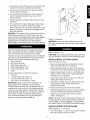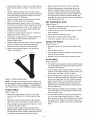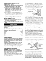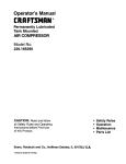
1
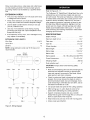
Operator's Manual
@
18"
4 Speed
Metal/Wood Cutting
BAND SAW
Model No.
351.224500
CAUTION: Read and follow
all Safety Rules and Operating
Instructions before First Use
of this Product.
Sears, Roebuck
and Co., Hoffman
www.sears.com/craftsman
20096.00 Draft (12/19/02)
Estates, IL 60179 U.S.A.
•
Warranty
....................................
SafetyRules...............................
Unpacking..................................
Assembly.................................
Installation
.................................
Operation.................................
Maintenance
..............................
Troubleshooting
.............................
PartsIllustrations
andLists..................
EspaSol
.................................
2
2-3
3
3-5
5-6
6-9
9-10
11
12-21
22-31
Be alert and think clearly. Never operate power tools
when tired, intoxicated or when taking medications
that cause drowsiness.
PREPARE
FULL ONE YEAR WARRANTY
WORK AREA
FOR JOB
•
Keep work area clean. Cluttered work areas invite
accidents.
•
Do not use power tools in dangerous environments.
Do not use power tools in damp or wet locations. Do
not expose power tools to rain.
•
Work area should be properly lighted.
•
Proper electrical receptacle should be available for
tool. Three-prong plug should be plugged directly
into properly grounded, three-prong receptacle.
•
Extension cords should have a grounding prong and
the three wires of the extension cord should be of
the correct gauge.
•
Keep visitors at a safe distance from work area.
If this product fails due to a defect in material or workmanship within one year from the date of purchase,
Sears will at its option repair or replace it free of
charge. Contact your nearest Sears Service Center
(1-800-4-MY-HOME) to arrange for product repair, or
return this product to place of purchase for replacement.
•
Keep children out of workplace. Make workshop
childproof. Use padlocks, master switches or remove
switch keys to prevent any unintentional use of
power tools.
If this product is used for commercial or rental purposes, this warranty will apply for 90 days from the date of
purchase.
• Always unplug tool prior to inspection.
•
Consult manual for specific maintaining and adjusting procedures.
This warranty applies only while this product is used in
the United States.
•
Keep tool lubricated and clean for safest operation.
•
Remove adjusting tools. Form habit of checking to
see that adjusting tools are removed before switching machine on.
•
Keep all parts in working order. Check to determine
that the guard or other parts will operate properly
and perform their intended function.
•
Check for damaged parts. Check for alignment of
moving parts, binding, breakage, mounting and any
other condition that may affect a tool's operation.
TOOL SHOULD
This warranty gives you specific legal rights and you may
also have other rights which vary from state to state.
Sears, Roebuck and Co., Dept. 817WA, Hoffman
Estates, IL 60179
WARNING:
For your own safety, read all of the
instructions and precautions before operating tool.
• A guard or other part that is damaged should be
properly repaired or replaced. Do not perform
makeshift repairs. (Use parts list provided to order
replacement parts.)
CAUTION: Always follow proper operating procedures
as defined in this manual -- even if you are familiar
with use of this or similar tools. Remember that being
careless for even a fraction of a second can result in
severe personal injury.
BE PREPARED
•
KNOW HOW TO USE TOOL
FOR JOB
Wear proper apparel. Do not wear loose clothing,
gloves, neckties, rings, bracelets or other jewelry
which may get caught in moving parts of machine.
•
Wear protective hair covering to contain long hair.
•
Wear safety shoes with non-slip soles.
•
Wear safety glasses complying with United States
ANSI Z87.1. Everyday glasses have only impact
resistant lenses. They are NOT safety glasses.
•
Wear face mask or dust mask if operation is dusty.
© Sears, Roebuck and Co.
BE MAINTAINED
•
Use right tool for job. Do not force tool or attachment
to do a job for which it was not designed.
•
Disconnect tool when changing blade.
• Avoid accidental start-up. Make sure that the tool is
in the "off" position before plugging in.
2
•
Do not force tool. It will work most efficiently at the
rate for which it was designed.
•
Keep hands away from moving parts and cutting
surfaces.
•
Never leave tool running unattended. Turn the power
off and do not leave tool until it comes to a complete
stop.
•
Do not overreach. Keep proper footing and balance.
•
Never stand on tool. Serious injury could occur if tool
is tipped or if blade is unintentionally contacted.
•
Know your tool. Learn the tool's operation, application and specific limitations.
•
Use recommended accessories (refer to page 15).
Use of improper accessories may cause risk of
injury to persons.
•
Handle workpiece correctly. Protect hands from possible injury.
•
Turn machine off if it jams. Blade jams when it digs
too deeply into workpiece. (Motor force keeps it
stuck in the work.) Do not remove summed or cut off
pieces until the saw is turned off, unplugged and the
blade has stopped.
WARNING: The operation of any power tool can result in
foreign objects being thrown into the eyes, which can
result in severe eye damage. Always wear safety goggles
complying with United States ANSI Z87.1 (shown on
package) before commencing power tool operation.
Safety goggles are available through your Sears catalog.
Check for shipping damage. If damage has occurred, a
claim must be filed with carrier. Check for completeness. Immediately report missing parts to dealer.
The band saw comes assembled as one unit. Additional
parts which need to be fastened to the saw should be
located and accounted for before assembling:
A Table Assembly
B Rip Fence with Knob
C Miter Gauge Assembly
D Metal Cutting Blade, 14TPI
E Wood Cutting Blade, 8 TPI
F V-belt
Hardware Bag (Part No. 20097.00) includes:
•
Wire Nut
•
•
•
10/12mm Open End Wrench (1)
12/14mm Open End Wrench (1)
3mm and 4mm Hex Wrench (1 each)
IMPORTANT: Table is coated with a protectant. To
ensure proper fit and operation, remove coating.
Coating is easily removed with mild solvents, such as
mineral spirits, and a soft cloth. Avoid getting solution
on paint or any of the rubber or plastic parts. Solvents
may deteriorate these finishes. Use soap and water on
paint, plastic or rubber components. After cleaning,
cover all exposed surfaces with a light coating of oil.
Paste wax is recommended for table top.
B
C
Figure 1 - Unpacking
WARNING:
Never use highly volatile solvents. Non
flammable solvents are recommended to avoid possible
fire hazard.
Refer to Figure 2, 6-11.
CAUTION: Do not attempt assembly if parts are missing. Use operator's manual to order replacement parts.
INSTALL
METAL CUTTING
BLADE
Refer to Figures 2, 8 and 9.
•
Make sure blade teeth are pointing down towards
table. Turn blade inside out if necessary.
•
Rotate handwheel (Figure 8, Key No. 23) counterclockwise to move blade wheels towards each other.
•
Loosen handle (Figure 9, Key No. 30). Rotate knob
(Figure 9, Key No. 22) to lower upper blade guide
assembly as low as possible.
•
Loosen two screws (Figure 9, Key No. 5). Remove
blade guard (Figure 9, Key No. 4).
•
Slip blade over upper and lower blade wheels, and
center blade on blade wheels. Slide blade in
•
between blade guides.
Rotate handwheel clockwise to tension blade.
•
Replace blade guard and secure in place by tightening screws. Raise upper blade guide assembly.
•
Position clutch handle (Figure 8, Key No. 60) to
"Metal". See Figure 2.
NOTE: The blade must be tensioned and tracked, and
the blade guides must be adjusted before operation of
the saw. Refer to "Tensioning Blade", "Tracking Blade"
and "Blade Guides" in the OPERATION section, page 6.
INSTALL WOOD CUTTING
BLADE
Refer to figures 2, 7, 8, 9 and 11.
•
The V-belt (Figure. 11, Key No. 25) must be installed
first when using the saw to cut wood.
• Loosenknob(Figure7, KeyNo.14).PlaceV-belton
motoranddrivepulleys(Figure8,KeyNos.46and
5O).
• TensionV-beltby pushingdownon motormount
plateandtighteningknob.Beltis properlytensioned
whenlightpressureappliedto midpointof thebelt
producesabout1/2"deflection.
• Makesurebladeteetharepointingdowntowards
table.Turnbladeinsideoutif necessary.
• Rotatehandwheel
(Figure8,KeyNo.23)counterclockwise
to movebladewheelstowardseachother.
• Loosenhandle(Figure9,KeyNo.30).Rotateknob
(Figure9,KeyNo.22)tolowerupperbladeguide
assemblyas lowas possible.
• Loosentwoscrews(Figure9, KeyNo.5).Remove
bladeguard(Figure9,KeyNo.4).
• Slipbladeoverupperandlowerbladewheels,and
centerbladeonbladewheels.Slidebladein
betweenbladeguides.
• Replacebladeguardandsecurein placebytighteningscrews.Raiseupperbladeguideassembly.
• Rotatehandwheel
clockwise
to tensionblade.
• Positionclutchhandle(Figure8, KeyNo.60)to
"Wood".SeeFigure2.
Wood
Remove table stud (Key No. 15) from the table.
Position table assembly so that blade slides into
table slot. Position upper trunnion on tip of lower
trunnion, making sure that the carriage bolt goes
through the slot in the lower trunnion. Tighten knob
onto carriage bolt. Make sure table assembly tilts
smoothly on lower trunnion and secure by tightening
knob. Replace table stud.
SET HORIZONTAL
STOP
Refer to Figure 10.
•
•
•
When table is attached to frame, a bolt (Key No. 13)
is used for a horizontal stop.
Loosen trunnion knob and set table at 90 ° to blade
using a square.
Secure position of table with knob.
• Adjust bolt to contact bottom edge of table.
•
Lock bolt in position with hex nut (Key No. 14).
ATTACH RIP FENCE
Refer to Figure 10.
•
Rip fence (Key No. 5) rides in the slot of table (Key
No. 1).
•
Slide rip fence into slot.
•
Hold rip fence to table and fasten by threading knob
(Key No. 6) into rip fence.
•
Rip fence can be repositioned by loosening knob.
ALIGN TABLE
Metal
Refer to Figure 10.
•
The table must be aligned properly so that the blade
is at a right angle to the table and that the rip fence
is aligned with the blade.
•
Lock the table in the horizontal position. Mount the
rip fence on the table. Slide the rip fence next to, but
not touching, the blade. Lock the rip fence.
•
Check that the blade is aligned parallel with the rip
fence. If the blade and fence are not parallel, loosen
the four hex head bolts (Key No. 3) that secure the
upper trunnion (Key No. 2) on the table. Adjust the
table position so that the blade and rip fence are
parallel. Secure the table position by tightening the
four hex head bolts.
Figure 2 - Clutch Handle Position
NOTE: The blade must be tensioned and tracked, and
the blade guides must be adjusted before operation of
the saw. Refer to "Tensioning Blade", "Tracking Blade"
and "Blade Guides" in the OPERATION section, page 6.
Refer to Figure 10.
• After assembly, the table has to be aligned in order
to have the blade running through the center of the
slot in the table insert.
•
•
ATTACH TABLE
•
Remove the upper trunnion (Key No. 2) from the
lower trunnion (Key No. 9) by removing knob (Key
No. 11).
Remove the four hex head bolts and flat washers
(Key Nos. 3 and 4) from bottom of table (Key No. 1).
•
Place carriage bolt and guide block (Key Nos. 7 and
8) into slot of upper trunnion.
•
Carefully position upper trunnion above the four
tapped holes in bottom of table and secure with four
hex head bolts and flat washers. Make sure that the
carriage bolt protudes from the slot of trunnion.
4
To move table sideways, loosen four hex nuts (Key
No. 14) on the lower trunnion (Key No. 2). Move
lower trunnion to left or right until blade runs through
the center of slot. Tighten hex nuts and make sure
that table stays in position while nuts are being tightened.
INSTALL V-BELT (METAL
CUTTING)
Refer to Figures 6, 7 and 11.
•
•
•
•
Band saw uses a step-pulley drive system to provide
a selection of blade speeds for metal cutting.
Loosen knob (Figure 7, Key No. 14). Place V-belt
(Figure 11, Key No. 25) on idler pulley and motor
pulley (Figure 11, Key Nos. 23 and 26) with V-belt in
desired location on pulleys. (See Figure 6, Blade
Speeds, page 8.)
This tool is equipped with an approved 3 conductor
cord rated at 150V and a three prong grounding type
plug for your protection against shock hazards.
Grounding plug should be plugged directly into a properly installed and grounded 3-prong grounding-type
receptacle, as shown (Figure 3).
Properly
G_unding
Do not over tighten V-belts. Excessive tension on Vbelt will reduce life of belt. Belt is properly tensioned
when light pressure applied to midpoint of the belt
produces about ½" deflection.
Prong
3-Prong
Do not remove or alter grounding prong in any manner.
In the event of a malfunction or breakdown, grounding
provides a path of least resistance for electrical shock.
SAW TO FLOOR
•
If saw is not properly positioned on a flat surface, it
may develop excessive vibration.
•
Mount to a flat, level surface through holes on top of
base.
Refer to Figures 3, 4 and 5.
WARNING:
Do not permit fingers to touch the terminals of plug when installing or removing from outlet.
Plug must be plugged into matching outlet that is properly installed and grounded in accordance with all local
codes and ordinances. Do not modify plug provided. If it
will not fit in outlet, have proper outlet installed by a
qualified electrician.
Inspect tool cords periodically, and if damaged, have
them repaired by an authorized service facility.
MOTOR
The 115 Volt AC motor has the following specifications:
Horsepower (Maximum Developed) ...............
2
Voltage ...............................
115/230
Amps ....................................
14/7
Hertz .....................................
Phase ..................................
RPM ....................................
POWER
Outlet
Figure 3 - 3-Prong Receptacle
Tension V-belt by pushing down on motor mount
plate and tightening hex head bolt and hex nut.
MOUNT
Grounded
60
Single
1720
SOURCE
The motor is designed for operation on the voltage and
frequency specified. Normal loads will be handled safely on voltages not more than 10% above or below the
specified voltage.
Green (or green and yellow) conductor in cord is the
grounding wire. If repair or replacement of the electric
cord or plug is necessary, do not connect the green (or
green and yellow) wire to a live terminal.
Where a 2-prong wall
must be replaced with
receptacle installed in
Code and local codes
receptacle is encountered, it
a properly grounded 3-prong
accordance with National Electric
and ordinances.
WARNING:
This work should be performed by a qualified electrician.
A temporary 3-prong to 2-prong grounding adapter (see
Figure 4) is available for connecting plugs to a two pole
outlet if it is properly grounded.
Grounding
Running the unit on voltages which are not within the
range may cause overheating and motor burn-out.
Heavy loads require that the voltage at motor terminals
be no less than the voltage specified. Power supply to
the motor is controlled by a double pole locking rocker
switch. Remove the key to prevent unauthorized use.
Lug
If======_
Adapter_
"__J
S-Prong
Plug
\
\
II
\/1 11, II AKnown
Ground
INSTRUCTIONS
WARNING:
Improper connection of equipment
grounding conductor can result in the risk of electrical
shock. Equipment should be grounded while in use to
protect operator from electrical shock.
Check with a qualified electrician if grounding instructions are not understood or if in doubt as to whether the
tool is properly grounded.
2-Prong
Figure
4 - 2-Prong
Receptacle
Is
II Connected
To
_
GROUNDING
Make Sure
This
with
Receptacle
Adapter
Do not use a 3-prong to 2-prong grounding adapter
unless permitted by local and national codes and ordinances. (A 3-prong to 2-prong grounding adapter is not
permitted in Canada.) Where permitted, the rigid green
tab or terminal on the side of the adapter must be
securely connected to a permanent electrical ground
such as a properly grounded water pipe, a properly
grounded outlet box or a properly grounded wire system.
Manycoverplatescrews,waterpipesandoutletboxes
arenotproperlygrounded.
Toensureproperground,
groundingmeansmustbetestedbya qualifiedelectrician.
EXTENSION
The Craftsman 18" Metal/Wood Cutting Band Saw is for
cutting ferrous and non-ferrous metals and also hard
and soft woods. The band saw features a unitized frame
of welded steel construction and a solid cast iron work
CORDS
•
The use of any extension cord will cause some drop
in voltage and loss of power.
•
Wires of the extension cord must be of sufficient size
to carry the current and maintain adequate voltage.
Use the table to determine the minimum wire size
(A.W.G.) extension cord.
•
Refer to Figures 6 - 11.
•
Use only 3-wire extension cords having 3-prong
grounding type plugs and 3-pole receptacles which
accept the tool plug.
•
If the extension cord is worn, cut or damaged in any
way, replace it immediately.
surface to ensure durability. Table tilts 45 ° and has a
miter gauge and precision machined rip fence for performing many different operations. Eighteen inch balanced cast iron wheels with ball bearings and rubber
treads accommodate blade widths up to 1". A convenient tensioning and tracking mechanism makes blade
changing quick and easy.
SPECIFICATIONS
Depth of throat ............................
EXTENSION CORD LENGTH
Maximum depth of cut ......................
Wire Size
A.W.G.
Up to 25 ft ..................................
25-50 ft ....................................
14
12
103/4"
Table size .............................
18 x 19"
Table tilt ...............................
0 to 45 °
Wheel diameter
NOTE: Using extension cords over 50 ft. long is not
recommended.
............................
18"
Blade length ..............................
Blade range ...........................
Switch
173/4"
Circuit
Breaker
133"
132-134"
Blade width ............................
Blade speeds ..........
3A0to 1"
80, 150, 200 and 2,800 FPM
Overall dimensions ..................
75 x 33 x 24"
Shipping weight .........................
280 Ibs
Dust collection port ...........................
2
Yellow
Red
CAUTION: Always observe the following safety
precautions:
#6
Black
L/
White
#5
?
•
Make sure that blade guides and thrust bearings are
positioned and adjusted correctly to prevent sideways and rearward movement of the blade. Adjust
upper guide to just clear workpiece.
•
Check to make sure blade is tensioned and tracking
properly. Do not over tension the blade in order to
prevent premature blade wear and breakage. Avoid
under tensioning to eliminate back and forth, side to
side blade movement as it cuts.
•
Use proper blade and speed for the cutting operation.
115V
L1
White
L2
Black
Yellow
#5
#6
Red
/
• After turning saw on, allow blade to come to full
speed before attempting any cutting operation.
/
5 -Wiring
•
Support workpiece properly and use a smooth
steady feed to guide work through the cut. Use push
sticks or push blocks when required.
•
Keep hands away and out of line with moving parts.
• Always wear eye protection.
230 V
L1
Figure
4"
L2
Diagram
6
REMOVING
BLADE
ALIGNMENT
OF DRIVE WHEEL
Refer to Figures 8 and 10.
Refer to Figure 11.
WARNING:
Disconnect band saw from power source
when changing or adjusting blades. Wear leather gloves
when handling band saw blades. Never wear gloves
when operating saw.
NOTE: Only attempt adjusting drive wheel alignment if
blade cannot be properly tracked with tracking adjustment alone.
•
Loosen hex nuts (Figure 8, Key No. 30) and rotate
handwheel (Figure 8, Key No. 23) to release blade
tension. Be careful; blade may spring from saw when
tension is released. Remove table stud (Figure 10,
Key No. 15), take out the released blade and replace
with another blade.
INSTALLING
•
BLADE
Although many of the adjustments may not be altered
when blade is removed, every adjustment should be
checked prior to using a newly installed blade.
•
Follow safety precautions every time saw is operated.
•
Make sure blade teeth are pointing down towards
table. Turn blade inside out if necessary.
•
•
Slip new blade into table slot and over upper and
lower blade wheels and center blade on blade
wheels. Slide blade in between blade guides.
Replace table stud.
• A blade under high tension may also pull drive wheel
out of alignment.
• Adjust alignment of drive wheel using hex head bolts
(Key Nos. 8 and 30).
BLADE
NOTE: Adjust blade guides only after blade has been
properly tensioned and tracked.
•
Blade guides support blade at sides and rear of
blade, and prevent twisting or deflection.
•
Blade guides should not touch blade when no workpiece is in contact with blade. Adjust guides as
described in following sections.
UPPER
•
Tension blade by rotating handwheel (Key No. 23). Be
sure blade guides do not interfere with blade path.
•
Tighten blade until it is properly tensioned.
GUIDES
•
Upper blade guides employ guide pins for side support and a ball bearing on an adjusting pin at rear.
•
Upper guide bracket (Key No. 13) should be positioned so guide on either side of blade will support
as much of blade width as possible without interfering with the tooth set.
BLADE
Refer to Figure 8.
BLADE
Refer to Figure 9.
Tension and track blade as described in the following
sections.
TENSIONING
GUIDES
• Adjust bracket depth by loosening bolts (Key Nos. 9
and 12) and sliding brackets into position. Secure
position of upper guide casting by tightening bolts.
•
A properly tensioned blade will ring slightly when back
of blade is plucked (like a string on an instrument).
NOTE: Check tension of new blade. Additional tension
may be required after a few minutes of operation.
Loosen set screws (Key No. 15) and adjust guide
pins (Key No. 14) to side of blade. Use a feeler gauge
to check that guide pins are .002" away from blade.
•
Lock adjustment by tightening set screws.
TRACKING
•
Position thrust bearing .002" away from back of blade.
•
Secure position of thrust bearing by tightening set
screw.
•
BLADE
Refer To Figure 8.
•
Track blade after it has been tensioned. A change in
blade tension will affect wheel alignment.
•
Proper tracking is achieved when drive and idler
wheels are aligned. Knob (Key No. 29) is used to tilt
tracking bar (Key No. 13) and align blade wheels.
•
Loosen hex nut (Key No. 30) which locks tracking
knob (Key No. 29). Turn idler wheel (Key No. 7) by
hand and observe how blade rides on wheels.
•
If blade rides away from cabinet, turn knob clockwise
to tilt idler wheel up.
•
If blade rides into cabinet, turn tracking knob counterclockwise.
•
When blade is tracking properly, lock position by
holding knob and tightening hex nuts (Key No. 30)
against the cabinet.
• Adjust thrust bearing (Key No. 17) at rear of blade by
loosening set screw (Key No. 15).
• Adjust the height of upper guide casting to clear the
workpiece by %'. Loosen knob (Key No. 30) and
rotate height adjustment knob (Key No. 22) until
upper blade guide bracket clears workpiece by %'.
Tighten knob.
LOWER
BLADE
GUIDES
Refer to Figure 9.
•
Lower blade guides employ two guide blocks for side
support. Lower guide bracket is spaced close to table
surface to minimize unsupported length of blade.
•
Loosen bolt (Key No. 19) to position lower guide
bracket on alignment block (Key No. 31 ). Adjust
lower guide bracket so guide blocks do not interfere
with blade set. Loosen set screws (Key No. 23) for
guide blocks (Key Nos. 21 and 34) and adjust guide
blocks to .002" from each side of blade.
Adjustthrustbearing(KeyNo.36)atrearofbladeby
looseningsetscrew(KeyNo.23).Positionthrust
bearing.002" away from back of blade. Secure posi-
•
Low cutting speeds are used on hard materials
when more force is required.
•
To change blade speed, position V-belt in proper
configuration (see Figure 6). Reposition and tension
V-belt as described in the next section.
tion of thrust bearing by tightening set screw.
BLADE
SELECTION
•
Blades vary depending on type of material, size of
workpiece and type of cut that is being performed.
•
Characteristics which make blades different are
width, thickness and pitch.
80 FPM ....................
150 FPM ...................
200 FPM .............
Steel and Steel Alloys
Cast Iron and Bronze
Aluminum, Brass and Copper
BLADE WIDTH
•
Width of blade describes distance from tip of a tooth
to back of blade.
•
Width of blade will affect rigidity of blade. A wider
blade will wander less and produce a straighter cut.
Width of blade also limits the smallest radius which
can be cut. A %" wide blade can cut about a ½"
radius.
•
80 FPM
Figure
BLADE THICKNESS
•
• A narrow thick blade would be used to cut curves
while a wide thin blade would be used to make long,
straight cuts.
•
The type of material being cut determines number of
teeth which should be in contact with work.
•
For soft metals, the proper blade has between 6 to
12 teeth per inch.
•
When cutting hard metals, where shocking is more
detrimental, use a blade with 12 to 24 teeth per inch.
•
For softwoods, the proper blade has 4 to 8 teeth per
inch.
CUTTING)
•
Blade speed is determined by the position of the
V-belt on the idler and motor pulleys (Figure 11, Key
Nos. 23 and 26). Blade speed is changed by changing pulley position of V-belt.
•
Be sure to disconnect saw from power and turn saw
OFF before attempting to change blade speed.
•
To change blade speed loosen motor mount plate
(Figure 7, Key No. 9) by loosening knob (Figure 7,
Key No. 14). Position V-belt on motor and idler pulleys as required. See Figure 6, Blade Speeds, for
recommended pulley and belt settings.
•
Tension V-belt by pushing down on motor mount
plate and tightening knob. Belt is properly tensioned
when light pressure applied to midpoint of the belt
produces about ½" deflection. Do not over tighten
V-belt.
PITCH
Pitch describes number of teeth per inch or tooth
size. A blade with more teeth per inch will produce a
smoother cut.
V-BELT (METAL
Refer to Figures 6, 7 and 11.
sides of blade. A thicker blade has more rigidity and
stronger teeth.
•
200 FPM
Speeds
REPOSITIONING
Blade thickness describes the distance between
BLADE
6 - Blade
150 FPM
CHANGING THE SAW OPERATION
METAL TO WOOD CUTTING
FROM
•
For hardwoods, the proper blade has 8 to 12 teeth
per inch.
•
There should always be at least three teeth in contact with cut to avoid shocking blade.
•
Remove metal cutting blade. See "Removing Blade"
above.
•
Blade shocking occurs when pitch is too large and
blade tooth encounters too much material. This can
•
Remove shroud (Figure 11, Key No. 28).
•
Loosen knob (Figure 7, Key No. 14). Remove V-belt
from motor and idler pulleys (Figure 11, Key Nos. 23
and 26).
•
Place V-belt on motor and drive pulleys (Figure 8,
Key Nos. 46 and 50).
•
Tension V-belt by pushing down on motor mount
plate and tightening knob. Belt is properly tensioned
when light pressure applied to midpoint of the belt
produces about 'tZ' deflection.
•
Change clutch handle from "metal" to "wood". (Refer
to Figure 2)
•
Replace shroud.
Refer to Figures 2, 7, 8 and 11.
strip teeth from blade.
•
Blade manufacturers are prepared to supply information about blades for specific applications.
BLADE
SPEED
Refer to Figure 6.
• The amount of force with which the blade cuts is
determined by speed.
•
High cutting speeds are used on soft materials
where less force is needed and a high rate of material removal is desired.
8
•
Install wood cutting blade. See "Installing Blade",
page 7. Properly tension, track and adjust blade
guides before operation.
CHANGING THE SAW OPERATION
WOOD TO METAL CUTTING
FROM
• Avoid passing hands beyond the cut. Use push
sticks or push blocks to finish cuts and pass workpiece away from blade.
CONTOUR
•
Refer to Figures 2, 7, 8 and 11.
•
•
Remove wood cutting blade. See "Removing Blade"
above.
Loosen knob (Figure 7, Key No. 14). Remove V-belt
from motor and drive pulleys (Figure 8, Key Nos. 46
and 50).
•
Remove shroud (Figure 11, Key No. 28).
•
Place V-belt on motor and idler pulleys (Figure 11,
Key Nos. 23 and 26).
•
Tension V-belt by pushing down on motor mount
plate and tightening knob. Belt is properly tensioned
when light pressure applied to midpoint of the belt
produces about '/2" deflection.
•
Change clutch handle from "wood" to "metal". (Refer
to Figure 2)
•
Replace shroud.
•
Install metal cutting blade. See "Installing Blade",
page 7. Properly tension, track and adjust blade
guides before operation.
TYPE OF CUT
•
Rip fence guides workpiece to produce straight cuts
on longer pieces.
•
Contour cutting is done by guiding workpiece freehanded to produce curved shapes.
•
Beveled cutting can be done by tilting table and
using proper work guide method.
•
Regardless of which work guiding method is used, a
workpiece which overhangs table by more than 7"
should be properly supported by support stands.
(See Recommended Accessories, page 15.)
RIP FENCE
SAWING
When contour sawing, use both hands to keep workpiece flat against table and guided along desired
path.
• Avoid positioning hands in line with blade. If hands
slip they could contact blade.
•
Try to stand to front of the saw and use hands over
the portion of table which is to right of blade and
before cut.
•
Cut small corners by sawing around them. Saw to
remove scrap until desired shape is obtained.
BEVEL
CUTTING
Refer to Figure 10.
•
Perform a bevel operation by tilting table. Loosen
knob (Key No. 11 ) and tilt table to desired position.
•
Use a square or protractor to set angle and lock
table in position with knob. Use caution when supporting work while bevel cutting. Do not allow work
to hang on blade.
MITER GAUGE
•
Use miter gauge for securing and holding workpiece
at desired angle to produce angled cuts. Use scale
to adjust gauge to desired angle.
•
Never use miter gauge and rip fence at the same
time. The blade might bind in the workpiece.
Operator could be injured and/or workpiece could be
damaged.
BLADE
CLEANING
BRUSH
Refer to Figure 8.
•
Make sure that brush (Key No. 36) is in contact with
blade to properly remove foreign particles from drive
wheel.
OPERATION
Refer to Figure 10.
•
Rip fence can be used to guide boards with one
square edge past blade when table is aligned properly.
•
Set rip fence to desired width of cut on inside of
throat. Remember to include the thickness of material that will be removed by blade.
•
Use a square to measure from tip of a tooth to
fence. Lock fence securely with knob (Key No. 6).
•
The portion of material between blade and fence is
considered the workpiece. Material on outside and
behind cut is the scrap material which is being cut
off. Use the right hand to keep work against fence.
•
Do not push on scrap portion of the work. This could
pinch or bind blade.
WARNING:
Make certain that unit is disconnected
from power source before attempting to service or
remove any component.
CLEANING
•
Keep machine and workshop clean. Do not allow
sawdust to accumulate on band saw.
•
Keep wheels clean. Debris on wheels will cause
poor tracking and blade slippage.
•
Keep mechanisms and threaded or sliding surfaces
clean and free of foreign particles.
•
Operate band saw with a dust collector to minimize
clean up.
LUBRICATION
• The shielded ball bearings are permanently lubricated and require no further lubrication.
•
Small amounts of machine oil can be applied to belt
tension mechanisms and threaded or sliding surfaces.
•
Occasionally apply a coat of automobile type wax to
table top to keep it slick and corrosion free.
KEEP BAND
SAW IN REPAIR
•
If power cord is worn or cut in any way, have it
replaced.
•
Replace V-belt and blade when they are worn.
Replace any damaged or missing part.
•
Use parts list to order parts.
10
SYMPTOM
POSSIBLE
Excessive blade breakage
1. Material not secure on table
Premature blade dulling
CORRECTIVE
CAUSE(S)
2. Incorrect speed or feed
3. Blade too coarse for material
4. Incorrect blade tension
5. Teeth in contact with work before
sawing
6. Blade rubs on wheel flange
7. Misaligned guides
8. Blade too thick for wheel diameter
1. Squarely place work on table
2. Check Blade Speed (Figure 6, page 8)
3. Use finer pitch blade
4. Tension blade properly; see "Operation"
5. Place blade in contact with work after saw is
started and has reached full speed
6. Adjust wheel alignment properly
7. Adjust blade guides properly
8. Use thinner blade
9. Cracking at weld
9. Replace blade
1. Blade too coarse
1. Use finer tooth blade
2. Excessive blade speed
3. Inadequate feed pressure
4. Hard spots or scale in or on
material
5. Work hardening of workpiece
6. Blade installed backwards
2. Try lower speed
3. Gently increase pressure
4. Reduce speed; increase rate of feed for
scale and change blades for hard spots
5. Increase rate of feed
7. Insufficient blade tension
Crooked cuts
ACTION
1. Work not square
2. Rate of feed too great
3. Blade guides not adjusted properly
6. Remove blade, twist inside out and reinstall
blade
7. Tension blade properly; see "Operation"
1. Use rip fence; adjust tilt of table at 90 ° to
blade
2. Reduce rate of feed
8. Blade guide assembly loose or
blade thrust bearing loose
3. Move both guide blocks within .002" from
blade (use gauge)
4. Tension blade properly; see "Operation"
5. Adjust upper guide to just clear workpiece
by %"
6. Replace blade
7. Check Blade Speed; see Figure 6, page 8 for
recommended speeds
8. Tighten blade thrust bearing within .002"
behind blade back
Rough cuts
1. Too much speed or feed
2. Blade too coarse
. Reduce speed
or feed
2. Replace with finer blade
Blade is twisting or unusual
wear on side/back of blade
1. Cut is binding blade
2. Blade guides or bearing worn
3. Blade guides or bearings not
adjusted properly
4. Blade guide brackets loose
1. Decrease feed pressure
2. Replace
3. Adjust blade guides; see "Operation"
4. Insufficient blade tension
5. Upper blade guide too far
from workpiece
6. Dull blade
7. Incorrect speed
Teeth ripping from blade
Motor running too hot
Saw will not start
1. Teeth too coarse for work
2. Rate of feed too great
3. Vibrating workpiece
4. Teeth filling with material
4. Tighten properly
1. Use blade with finer teeth
2. Decrease feed rate
3. Hold workpiece firmly
4. Use blade with coarser teeth
1. Blade tension too great
2. Blade too coarse for work
(typical when cutting pipe)
3. Blade too fine for work (typical
when cutting slick or soft material)
4. Excessive dirt and chips
Loose electrical connections
1. Reduce tension on blade
2. Use blade with finer teeth
3. Use blade with coarser teeth
4. Clean thoroughly; vacuum motor and speed
change mechanism
Have qualified electrician check electrical
connections
11
Model 351.224500
Figure 7 - Replacement
Parts Illustration
for Motor
25
/
23
20
\
24
22
21
6
26
o
o
o
o
J
12
12
\
17
KEY
NO.
PART NO.
DESCRIPTION
1
2
3
16080.00
03668.01
00361.00
Switch
Switch Plate
5-0.8 x 8mm Pan Head Screw
1
1
9
4
5
6
01474.00
STD840508
18970.00
5mm Serrated Washer
5-0.8mm Hex Nut*
Line Cord
2
1
1
7
8
9
18971.00
02434.00
08589.00
Motor Cord
Strain Relief
Motor Mount Plate
1
2
1
10
11
12
08590.00
18986.00
STD551037
Slide Bracket
3L-16 x 8" Carriage Bolt
_" Flat Washer*
1
1
3
13
14
15
08592.00
18953.00
08593.00
Spacer
Knob
Pivot Bracket
1
1
1
16
17
18
18985.00
STD561210
STD835020
Clevis Pin
Y_x 1" Cotter Pin*
8-1.25 x 20mm Hex Head Bolt*
1
2
4
19
20
05188.00
01634.00
8-1.25 x 20mm Carriage Bolt
Strain Relief
4
1
21
22
23
STD852008
STD840812
02813.00
8mm Lock Washer*
8-1.25mm Hex Nut*
24
25
26
18972.00
01090.00
06677.00
_6 x _/_o
x 1 Vz"Key
Motor
5-0.8 x 15mm Pan Head Screw
Strain Relief Plate
8
8
2
27
28
03981.00
04287.00
Cord Clamp
Circuit Breaker
*
QTY.
1
1
2
1
1
Standard hardware item available locally.
13
Model 351.224500
Figure 8 - Replacement
Parts Illustration
for Front
31
\
22
18
/
25
20
26
19
16
13
lO
6
14
11
2O 15
/
8
41
53
12
62
/
10
<
\
44
35
43
60
59
45
34
8
6
14
KEY
NO.
PART NO.
DESC RIPTION
1
2
N/A
08596.01
Frame
1
3
4
5
08597.01
03663.00
08304.00
Upper Cabinet Door
Lower Cabinet Door
1
1
Knob (External Threads)
Latch
2
2
6
7
8
00964.00
08598.00
08599.00
6-1.0 x 6mm Set Screw
Idler Wheel
Rubber Tread
9
1
2
9
10
03838.00
STD315235
11
12
13
08600.00
00341.00
03605.01
14
STD835025
15
STD852008
16
17
18
03608.00
03606.00
03609.00
19
STD835070
QTY.
3BMI-40 Retaining Ring
6203ZZ Bearing*
Idler Shaft
2
2
1
3AM1-17 Retaining Ring
1
Tracking Bar
8-1.25 x 25mm Hex
Head Bolt*
8mm Lock Washer*
1
1
KEY
NO.
PART NO.
DESCRIPTION
33
34
STD841015
18973.00
10-1.5mm Hex Nut*
Drive Wheel
1
1
35
36
37
07904.00
20071.00
03620.00
3BMI-42 Retaining Ring
Brush
Bracket
2
1
1
38
17741.00
4.8-2.1 x 8mm Thread
2
39
00361.00
Forming Screw
5-0.8 x 8mm Pan Head
1
40
STD851005
Screw
5mm Flat Washer*
2
41
42
43
08439.00
00958.00
00256.00
17mm Wavy Washer
8-1.25 x 8mm Set Screw
1
1
44
00483.00
3AMI-20 Retaining Ring
8-1.25 x 25mm Socket
Head Bolt*
1
7
6004ZZ Bearing*
Drive Pulley
Drive Clutch
8-1.25 x 20mm Hex Head
2
1
1
3
Bolt*
Movable Clutch
1
Motor Pulley
Metal Cutting Blade, 14 TPI
Wood Cutting Blade, 8 TPI
Cam
1
1
1
1
Shift Bar
Stud
1
1
12
45
STD315545
Tracking Adjustment Bracket
Tension Bracket
1
1
2
2
46
47
48
18975.00
18927.00
STD835020
18928.00
18976.00
QTY.
20
STD851008
Upper Cabinet Support
8-1.25 x 70mm Hex
Head Bolt*
8mm Flat Washer*
8
49
50
21
22
23
STD840812
08601.01
05598.01
8-1.25mm Hex Nut*
Threaded Shaft
Handwheel
9
1
1
51
52
53
18977.00
20098.00
18934.00
24
25
03610.00
STD833016
Tension Support
6-1.0 x 16mm Hex
Head Bolt*
1
8
54
55
56
18979.00
18931.00
16895.00
26
27
28
STD851006
STD840610
03607.00
6mm Flat Washer*
6-1.0mm Hex Nut*
Tension Nut
16
8
1
57
58
59
STD551031
16981.00
02681.00
Pillow Block with Bushing
5/_6"Flat Washer*
Collar
8-1.25 x 12mm Socket Head
2
1
2
3
29
30
08307.00
STD541031
Tracking Knob
5Zc,"-18Hex Nut*
1
2
60
18933.00
Bolt
Clutch Handle
1
31
32
08308.00
STD851010
10-1.5mm Eye Bolt
10mm Flat Washer*
1
1
61
62
20073.00
18942.00
_/2"-12x _3/_0
Ball Plunger
Knob
1
1
* Standard hardware item available locally.
A Not Shown.
Recommended
A
15
Accessories
Support Stand
9-21417
A
3-Roller Support Stand
9-22265
A
:Y4"Carbon Blade, 4 TPI
9-26656
A
:Y4"Carbon Blade, 6 TPI
9-26631
A
:Y_"Carbon Blade, 10 TPI
9-26657
A
:Y_"Carbon Blade, 12 TPI
9-26635
A
%" Carbon Blade, 14 TPI
9-26658
Model 351.224500
Figure 9 - Replacement
Parts Illustration
for Blade Guides
19
23
23
1
o
2
o
o
o
i
i
i
9
10.
14
17
/
\
16
KEY
NO.
PART NO.
DESCRIPTION
1
2
3
09562.00
08605.00
06045.00
Guide Bar
Rack
5-0.8 x 20mm Socket Head Bolt
1
1
3
4
5
6
09563.00
03619.01
STD551031
Blade Guard
Thread Forming Screw
_/_0"Flat Washer*
1
2
1
7
8
9
08314.00
06607.00
STD833025
Guide Attaching Bracket
Guide Depth Bracket
6-1.0 x 25mm Hex Head Bolt*
1
1
2
10
11
12
STD851006
STD840610
STD833016
6mm Flat Washer*
6-1.0mm Hex Nut*
6-1.0 x 16mm Hex Head Bolt*
15
2
10
13
14
15
08316.00
08317.00
00958.00
Upper Guide Bracket
Guide Pin
8-1.25 x 8mm Set Screw
1
2
3
16
17
18
08318.00
STD315205
01434.00
Bearing Pin
6200ZZ Bearing*
1
1
1
19
20
STD833012
06617.00
21
22
23
08298.00
08320.00
00964.00
24
25
26
STD851010
08322.00
06323.00
27
28
29
01097.00
09564.00
08324.00
30
31
32
08352.00
06376.00
08325.15
33
34
35
08353.00
08354.00
08355.00
36
STD315485
*
QTY.
3CM1-10 E-Ring
6-1.0 x 12mm Hex Head Bolt*
Guide Casting
Guide Block
Knob (Internal Threads)
6-1.0 x 6mm Set Screw
10mm Flat Washer*
Pinion Shaft Assembly
3CMI-8 E-Ring
6-1.0 x 35mm Socket Head Bolt
Spring
Positioning Block
Handle
Alignment Block
%_-18 x 1%" Hex Low Head Bolt
Lower Guide Bracket
Guide Block
Bearing pin
608ZZ Bearing*
1
1
1
1
6
1
1
1
1
1
1
1
1
1
1
1
1
1
Standard hardware item available locally.
17
Model
351.224500
Figure 10 - Replacement Parts Illustration forTable
25
16
30
1
.22
14
24
8
\
17
\
\
32
18
KEY
NO.
PART NO.
DESCRIPTION
1
2
18980.00
05185.02
Table
3
4
5
STD523107
STD551031
05351.00
6
7
8
00010.00
STD533120
05186.00
9
10
11
05187.00
08634.00
03659.00
12
13
Upper Trunnion
_/_0-18x _14"Hex Head Bolt*
%" Flat Washer*
Rip Fence
Knob (External Threads)
%-18 x 2" Carriage Bolt*
Guide Block
Lower Trunnion
QTY.
1
1
4
9
1
1
1
1
1
1
1
STD523110
STD523117
4 x 12mm Spring Pin
Knob (Internal Threads)
_/_0-18x 1" Carriage Bolt*
_/_0-18x 1_14
'' Hex Head Bolt*
4
1
14
15
16
STD541031
08331.00
08609.00
_1_o"-18Hex Nut*
Table Stud
Table Insert
5
1
1
17
18
19
01883.00
01093.00
08256.00
5-0.8 x 8mm Flat Head Screw
Guide
1
1
1
20
21
22
08251.00
08250.00
08049.00
23
24
25
01605.00
05991.00
08252.00
26
27
28
STD541010
STD511007
08253.00
Knob (Internal Threads)
#10-24 Hex Nut*
#10-24 x 3/4"Pan Head Screw*
Indicator
29
30
31
08254.00
STD551010
08255.00
Scale
#10 Flat Washer*
Threaded Pin
1
1
1
32
08257.00
Miter Gauge Assembly (Key Nos. 17 - 31)
1
Indexing Pin
Miter Gauge
Miter Gauge Bar
#10 Fiber Washer
#10-24 x 1/4"Washer Head Screw
#10-24 x ½" Flat Head Screw
* Standard hardware item available locally.
19
1
1
1
1
2
1
3
3
1
Model 351.224500
Figure
11 - Replacement
Parts Illustration
for Gear Box
6
11
9
3o
21
4
37
12
33
lO
9
7
14
15
16
22
1
3
13
35
23
17
19
2O
KEY
NO.
PART NO.
DESCRIPTION
QTY.
1
2
08332.00
07904.00
Shaft Support
1
2
3
4
5
6
STD315545
18982.00
18938.00
08661.00
7
8
01900.00
STD835030
9
10
11
STD852008
STD835020
08611.00
12
13
14
17586.00
17587.00
01822.00
15
16
17
08338.00
08496.00
01861.00
18
19
2O
08500.00
STD315205
08497.00
21
22
23
08498.00
08438.00
08344.00
24
25
26
STD851010
STD304470
08615.00
27
28
00964.00
18983.01
Motor Pulley
6-1.0 x 6mm Set Screw*
Shroud
2
1
29
30
31
00361.00
STD835025
STD836020
5-0.8 x 8mm Pan Head Screw
8-1.25 x 25mm Hex Head Bolt*
10-1.5 x 20mm Hex Head Bolt*
4
4
1
32
33
34
00256.00
17588.00
18968.00
3AMI-20 Retaining Ring
Seal
25 x 42 x 7mm Oil Seal
2
1
1
35
36
37
17590.00
17591.00
20078.00
20 x 36 x 7mm Oil Seal
1
2
1
A
A
18984.00
20097.00
20096.00
A
3BMI-42 Retaining Ring
6004ZZ Bearing*
Wheel Drive Shaft
Seal
7 x7 x 15mm Key
3AMI-25 Retaining Ring
8-1.25 x 30mm Hex Head Bolt*
8mm Lock Washer*
8-1.25 x 20mm Hex Head Bolt*
Lower Cabinet Support
Gear Box
Gear Box Cover
8-1.25 x 20mm Socket Head Bolt
6 x 20mm Dowel Pin
Gear
3AMI-22 Retaining Ring
Gear Shaft
6200ZZ Bearing*
Pulley Drive Shaft
6905ZZ Bearing
5 x5 x 30mm Key
Idler Pulley
10mm Flat Washer*
V-Belt*
Plug
Grease Fitting
Gearbox Assembly
Hardware Bag
Operator's Manual
* Standard hardware item available locally.
A Not Shown.
21
2
1
1
2
2
4
10
6
1
1
1
9
2
2
2
1
2
1
2
1
1
1
1
1
1
1
1
22
23
24
25
26
27
28
29
30
31
Your Home
For repair-in
your home-of all major brand appliances,
lawn and garden equipment, or heating and cooling systems,
no matter who made it, no matter who sold it!
For the replacement parts, accessories and
owner's manuals that you need to do-it-yourself.
For Sears professional installation of home appliances
and items like garage door openers and water heaters.
1-800-4-MY-HOME
Call anytime,
®
(1-800-469-4663)
day or night (U.S.A. and Canada)
www.sears.com
www.sears.ca
Our Home
For repair of carry-in items like vacuums, lawn equipment,
and electronics, call or go on-line for the location of your nearest
Sears Parts & Repair Center.
1-800-488-1222
Call anytime,
day or night (U.S.A. only)
www.sears.com
To purchase a protection
1-800-827-6655
agreement
on a product serviced by Sears:
(U.S.A.)
Para pedir servicio de reparaci6n
a domicilio, y para ordenar piezas:
1-888-SU-HOGAR
1-800-361-6665
(Canada)
Au Canada pour service en frangais:
1-800-LE-FOYER
SM
Mc
(1-800-533-6937)
www.sears.ca
(1-888-784-6427)
SEARS
SM
® Registered Trademark / TM Trademark /
Service Mark of Sears, Roebuck and Co.
® Marca Registrada
/ TM Marca de Fabrica
/ SM Marca de Servicio
de Sears,
Roebuck
and Co.
MC Marque
de commerce
/
MD
Marque
dCpos_e
de Sears,
Roebuck
and Co.
© Sears,
Roebuck
and Co.