1
Operator's Manual
CRRFTSMRN
o
Bench Top
JOINTER/PLANER
Model No.
351.217680
CAUTION:
Read and follow
all Safety Rules and Operating
Instructions before First Use
of this Product.
Sears, Roebuck
and Co., Hoffman
16303.00 Draft (01/04/00)
Estates, IL 60179 U.S.A.
PREPARE WORK AREA FOR JOB
Warranty..................................
•
Keep work area clean. Cluttered work areas invite
accidents.
2
Safety Rules ..............................
2-3
•
Do not use power tools in dangerous environments.
Unpacking .................................
3
•
Assembly .................................
Installation ...............................
3
4-5
Do not use power tools in damp or wet locations. Do
not expose power tools to rain.
Operation ................................
Maintenance ............................
Troubleshooting ............................
Parts Illustration and List ..................
11
13-15
Espahol ...............................
16-26
FULL
ONE YEAR
• Work area should be properly lighted.
5-9
9-10
• Proper electrical receptacle should be available for
tool. Three prong plug should be plugged directly
into propedy grounded, three-prong receptacle.
•
the correct gauge.
•
Keep visitors at a safe distance from work area.
•
Keep children out of workplace. Make workshop childproof. Use padlocks, master switches or remove switch
keys to prevent any unintentional use of power tools.
WARRANTY
If this product fails due to a defect in material or workmanship within one year from the date of purchase,
Sears will at its option repair or replace it free of
charge.
TOOL
Contact your nearest Sears Service Center to arrange
for product repair, or return this product to place of purchase for replacemnt.
If this product is used for commercial or rental purposes, this warranty will apply for 90 days from the date of
purchase.
This warranty gives you specific legal rights, and you
may also have other dghts which vary from state to
state.
Sears, Roebuck and Co., Dept. 817WA, Hoffman
Estates, IL 60179
CAUTION: Always follow proper operating procedures
as defined in this manual even if you are familiar with
use of this or similar tools. Remember that being careless for even a fraction of a second can result in severe
personal injury.
SHOULD
BE MAINTAINED
•
Always unplug tool prior to inspection.
•
Consult manual for specific maintaining and adjusting procedures.
•
Keep tool lubricated and clean for safest operation.
•
Remove adjusting tools. Form habit of checking to
see that adjusting tools are removed before switching machine on.
•
Keep all parts in working order. Check to determine
that the guard or other parts will operate propedy
and perform their intended function.
•
Check for damaged parts. Check for alignment of
moving parts, binding, breakage, mounting end any
other condition that may affect a tool's operation.
•
A guard or other part that is damaged should be
prepedy repaired or replaced. Do not perform
makeshift repairs. (Use parts list provided to order
replacement parts.)
WARNING:
For your own safety, road all of the rules
and precautions before operating tool.
BE PREPARED
Extension cords should have a grounding prong and
the three wires of the extension cord should be of
KNOW HOWTO
USE TOOL
•
Use right tool for job. Do not force tool or attachment
to do a job for which it was not designed.
•
Disconnect tool when changing blades.
•
Avoid accidental start-up. Make sure that the switch
is in the OFF position before plugging in.
•
Do not force tool. It will work most efficiently at the
rate for which it was designed.
•
Keep hands away from moving pads and cutting
surfaces.
Never leave tool running unattended. Turn the power
off and do not leave tool until it comes to a complete
stop.
FOR JOB
•
Wear proper apparel. Do not wear loose clothing,
gloves, neckties, rings, bracelets or other jewelry
which may get caught in moving parts of machine.
•
Wear protective hair covering to contain long hair.
•
Wear safety shoes with non-slip soles.
•
•
Wear safety glasses complying with United States
ANSi Z87.1. Everyday glasses have only impact
resistant lenses. They are NOT safety glasses.
• Do not overreach. Keep proper footing and balance.
• Wear face mask or dust mask if operation is dusty.
•
Be alert and think clearly. Never operate power tools
when tired, intoxicated or when takin9 medicat'_ons
that cause drowsiness.
2
•
Never stand on tool. Serious injury could occur if tool is
tipped or if blade is unintentionally contacted.
•
Know your tool. Learn the tool's operation, application and specific limitations.
•
Use recommended accessories (refer to page 15).
Use of improper accessories may cause risk of
injury to persons.
•
Handle workpiece correctly. Protect hands from possible injury.
Turn machine off if it jams. Blade jams when it digs
too deeply into workpiece. (Motor force keeps it
stuck in the work.)
•
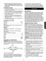
Refer to Figure 2.
ASSEMBLE
FENCE
BRACKETTO
FENCE
•
Lay the fence flat on a level surface so that the surface with the slots is on the top (facing you) and the
beveled fence edge coming toward you.
•
Always keep drive, cutterhead and blade guards in
place and in proper operating condition.
•
Make two vertical marks across the fence width
using a pencil at 103/,6"from each side of the fence.
•
Feed work into blade or cutter against direction of
rotation.
•
Slide two square nuts, one on each slot, from the right
side of fence so that the center of the hex nuts are
CAUTION: Think safety! Safety is a combination of
operator common sense and alertness at all times
when tool is being used.
aligned with the pencil mark.
•
Slide two square nuts from the left side of the fence
up to the pencil mark.
WARNING:
Do not attempt to operate tool until it is
completely assembled according to the instructions.
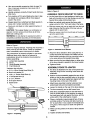
Refer to Figure 1.
Check for shipping damage. If damage has occurred, a
claim must be filed with carrier. Check for completeness. Immediately report missing parts to dealer.
Figure 2 - Assemble Fence Bracket
The jointer/planer is shipped complete in one carton.
Additional parts which need to be fastened to
jointer/planer should be located and accounted for
before assembling.
A
B
C
D
Jointer Bed Assembly
Fence
Fence Bracket Assembly
Push Blocks (2)
6-1.0 x 16mm Socket Head Bolts (2)
6mm Lock washer (2)
•
•
'/,-20 x '/2" Socket Head Bolts (4)
V,'-2O Square Nuts (4)
•
3, 4, 5 L-Wrench
•
•
8-10 Open Wrench
Screw Driver
A
Attach the fence bracket to fence using the four '/,"
socket head bolts and square nuts. Make sure the
fence bracket protrusion with two mounting holes is
in the same side as the beveled fence edge.
•
Make sure that the two slotted plates on either side
of the fence bracket is parallel to the fence bracket.
• Tighten all bolts.
ASSEMBLE FENCE TO JOINTER
Hardware bag includes:
•
•
•
•
The fence is attached to the rear of the jointer bed
assembly using the two mounting holes below the
cutterhead.
•
Position the fence assembly against the rear of the
jointer so that the two mounting holes on the protrusion plate on the fence bracket are aligned with the
mounting holes on the rear of the jointer.
•
Attach fence assembly to jointer using two 6mm
socket head bolts and lock washers provided.
•
Loosen the handle on the rear of the fence bracket.
•
The fence assembly can be slid forward now.
•
Slide fence assembly forward so that the fence is
over the jointer tables. At this position the edge of
the blade guard will rest against the fence, and the
entire width of the cutterhead is covered.
•
Place a combination square against face of fence
and table surface. The fence and table must be at
90" to each other. If not, loosen the tilt handle and
bring face of fence square to table and tighten tilt
handle.
•
Make sure the pointer on the side of fence bracket
reads 0°.
• Tighten all bolts and handles.
Figure I - Unpacking
3
The jointer/planer weighs approximately 30 Ibs. when
completely assembled. The jointer/planer must be
installed in a place with ample lighting and correct
power supply. To install jointer/planter:
•
•
This tool is equipped with an approved cord rated at
150V and a 3-prong grounding type plug (see Figure
4) for your protection against shock hazards.
•
Grounding plug should be plugged directly into a
properly installed and grounded 3-prong groundingtype receptacle, as shov,'q (see Figure 4).
Properly Grounded Outlet
Make sure there is plenty of room for moving the
workpiece through the entire cut. There must be
enough room that neither the operators nor the
bystanders will have to stand in line with the wood
while using the tool.
•
3-Prong P!ug
Jointer/planer can be installed on work using bolts,
lock washers and hex nuts (not supplied) or using
wood screws (not supplied).
•
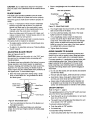
The %2"holes (see Figure 3) are intended for
installing jointer/planer using wood screws.
•
Bolt or clamp the jointer/planer to a firm, level surface.
•
Make sure the jointedplaner
tables are level.
does not rock and the
18'/_"
Figure 3 - Installing JointedPlaner
•
Inspect tool cords periodically, and it damaged, have
repaired by an authorized service facility.
•
Green (or green and yellow) conductor in cord is the
grounding wire. If repair or replacement of the electric cord or plug is necessary, do not connect the
green (or green and yellow) wire to a live terminal.
•
A 2-prong wall receptacle must be replaced with a
properly grounded 3-prong receptacle installed in
accordance with National Electric Code and local
codes and ordinances.
Grounding Lug
Adapter_
_
Make Sure This
i========_
Is Connected
"X%_
I To A Known
Ground
3 Pron__
Power supply to the motor is controlled by a rocker
switch. Removing the key from rocker switch will lock
the unit and prevent unauthorized use.
2-Prong Receptacle
Figure 5 - 2-Prong Receptacle with Adapter
• Do not use a 3-prong to 2-prong grounding adapter
unless permitted by local and national codes and
ordinances. (A 3-prong to 2-prong grounding adapter
is not permitted in Canada.)
INSTRUCTIONS
WARNING:
Improper connection of equipment
grounding conductor can result in the risk of electrical
shock. Equipment should be grounded while in use to
protect operator from electrical shock.
•
Plug must be plugged into matching outlet that is
properly installed and grounded in accordance with
all local codes and ordinances. Do not modify plug
provided. If it will not fit in outlet, have proper outlet
installed by a qualified electrician.
A temporary 3-prong to 2-prong grounding adapter (see
Figure 5) is available for connecting plugs to a two pole
outlet if it is properly grounded.
The motor is designed for operation on the voltage and
frequency specified. Normal loads will be handled safely on voltages not more than 10% above or below specified voltage. Running the unit on voltages which are not
within range may cause overheating and motor burnout. Heavy loads require that voltage at motor terminals
be no less than the voltag e specified on nameplate.
GROUNDING
•
WARNING: Any receptacle replacement should be
performed by a qualified electrician.
SOURCE
WARNING:
Do not connect jointedplaner to the power
source until all assembly steps have been completed.
•
Do not remove or alter grounding prong in any manner.
In the event of a malfunction or breakdown, grounding
provides a path of least resistance for electrical shock.
WARNING:
Do not permit fingers to touch the terminals of plug when installing or removing from outlet.
17V,"
POWER
:_=,,'a_/"_
Figure 4 - 3-Prong Receptacle
• The '/," holes {see Figure 3) are intended for installing
jointer/planer using bolts, lock washers and hex nuts.
•
i_--=-'--_
Where a 3-prong to 2-prong grounding adapter is
permitted, the rigid green tab or terminal on the side
of the adapter must be securely connected to a
permanent electrical ground such as a properly
grounded water pipe, a properly grounded outlet box
or a properly grounded wire system.
Check with a qualified electrician if you do not
understand grounding instructions or if you are in
doubt as to whether the tool is properly grounded.
4
•
Many cover plate screws, water pipes and outlet
boxes are not properly grounded. To ensure proper
ground, grounding means must be tested by a qualified electrician.
EXTENSION
The use of any extension cord will cause some drop
in voltage and loss of power.
•
Wires of the extension cord must be of sufficient size
to carry the current and maintain adequate voltage.
Use the table to determine the minimum wire size
(A.W.G.) extension cord.
•
Use only 3-wire extension cords having 3-preng
grounding type plugs and 3-pole receptacles which
accept the tool plug.
•
If the extension cord is worn, cut or damaged in any
way, replace it immediately.
EXTENSION
Remove the key to prevent unauthorized use.
The power lines are inserted directly onto the switch.
The green ground line must remain securely fastened
to the frame to properly protect against electrical shock.
CORDS
•
•
•
DESCRIPTION
Craftsman 6'/8" jointer/planer is used to surface the faces
and edges of boards, produce a flat surface on warped
boards and shape bevels, chamfers and tapers. The jointer/planer features cast aluminum infeed and outfeed
tables, lightweight plastic body with smooth work surfaces and leadscrews for precise table height adjustment.
Balanced guide fence tilts 45" (inward) and 45" (outward).
Tool comes with locking rocker switch with removable key
and push blocks. Jointer/planer easily handles rough-cut
lumber, planes hard and soft woods up to 6'/6" wide using
a two blade cutterhead, and takes cuts up to '/8"
CORD LENGTH
Wire Size
A.W.G.
Up to 50 ft ................................
16
OPERATION
50-100 ft ..................................
14
Jointing is a surfacing operation in which a small
amount of wood is removed from the edges and faces of
boards to get smooth, straight and even surfaces such
that the two edges that run across the planing blocks
would fit together perfectly, forming a seamless joint.
NOTE: Using extension cords over 100 ft. long is not
recommended.
MOTOR
Jointer/planer is supplied with a 1'/2 HP (max developed) motor.
Voltage .....................
"............
1_/2
10
Hertz ....................................
60
ELECTRICAL
WARNING:
WARNING:
Operation of any power tool can result in
foreign objects being thrown into eyes which can result
in severe eye damage. Always wear safety goggles
complying with United States ANSI Z87.1 (shown on
package) before commencing power tool operation.
120
Amps ...................................
Phase ................................
RPM ..................................
Single
8000
WARNING:
For your own safety, read all of the
instructions and safety precautions before operating
tool.
CONNECTIONS
•
Make sure unit is turned oft and discon-
nected from power source before inspecting any wiring.
Know general power tool safety. Make sure all precautions are understood (see pages 2, 3, 5 and 6).
• Whenever adjusting or replacing any parts on
jointer/planer, turn switch oft and remove plug from
power source.
The unit is wired as illustrated in the wiring schematic
(see Figure 6).
Switch
White'L_
RULES
Planing refers to the sizing of lumber to a desired thickness while creating a level surface parallel to the opposite size of the board. Depth of cut is the term used to
indicate how deep the blades will cut into the workpiece.
The 120 Volt AC universal motor has the following
specifications:
Horsepower (Maximum Developed) .............
SAFETY
White
i
•
Make sure all guards are properly attached and
securely fastened.
•
Make sure all moving parts are free from interference.
•
Always wear eye protection or face shield.
•
Make sure blades are aligned and properly attached
to cutterhead.
•
Do not plug in jointer/planer unless switch is in "off"
position. After turning switch on, allow jointer/planer
to come to full speed before operating.
•
Keep hands clear of all moving parts.
•
Do not force cut. Slowing or stalling will overheat
motor,
Figure 6 - Wiring Schematic
The motor is assembled with an approved three conductor cord to be used on 120 volts as indicated. The
power supply to the motor is controlled by a double
- pole locking rocker switch.
5
•
Use quality lumber. Blades last longer and cuts are
smoother with good quality wood.
•
Do not perform jointing/planing operations on material shorter than 8'!,", narrower than _/,", or _ess than
_/4"thick
•
Never make jointing cut deeper than '/,".
•
Always keep cutterhead and blade guards in proper
working condition.
Outteed
Table
Maintain the proper relationships of infeed and outfeed table surfaces and cuttarhead blade path.
• Do not back the work toward the infeed table.
Max Depth
of Cut %"
•
•
Support the workpiece adequately at all times during
operation; maintain control of the workpiece.
•
Use hold-down/push blocks for jointing material narrower than 3" or planing material thinner than 3".
Figure 8 - Check Depth of Cut
NOTE: This jointer/planer will make a maximum %"
deep cut. To reduce the danger of kickback and possible injury, the depth of cut should not exceed '/,6".
CAUTION: Make sure the switch is in the "off" position
and the cord is unplugged from power source before
performing this check.
• Take precautions against kickback. Do not permit anyone to stand or cross in line of cutterheadis rotation.
Kickback or thrown debris will travel in this direction.
POSITIONING
FENCE
•
Turn switch off and disconnect power whenever
jointer/planer is not in use.
The fence can be adjusted to cut various angles from
0"-45" inward and outward. The fence can be tilted
•
Replace or sharpen blades as they become damaged
or dull.
•
Do not attempt to perform an abnormal or little used
operation without study and the use of adequate holddown/push blocks, jigs, fixtures, stops and the like.
inward up to 45" (toward the cutterhead) to maintain
greater stability of a narrow workpiece or up to 45 ° outward (away from cutterhead) for larger angle cutting
operations.
•
To adjust tilt angle:
Keep jointer/planer maintained. Follow maintenance
instructions (see pages 9-10).
DEPTH
•
Loosen fence tilt handle.
•
The fence tilt handle is spring loaded. To continue
turning the handle, gently pull the handle away from
the fence and return it to the original position.
•
Release the handle and continue loosening.
•
Manually tilt fence inward/outward to the desired
angle. Use the scale on the left side of fence bracket
to measure tilt angle.
OF CUT
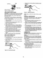
Refer to Figure 7.
The depth of cut is adjusted by the relative positioning
of the infeed table with respect to the cutterhead. Infeed
table can be raised or lowered using the handwheel.
Turning the handwheel counterclockwise will lower the
infeed table causing more wood to be removed from
workpiece. Turning the handwheel clockwise will raise
the infeed table causing less wood to be removed from
workpiece.
NOTE: The fence has positive stops at 0" (90" from
table) and at 45" inward.
•
Tighten fence tilt handle.
•
To continue tightening, gently pull the handle away
from fence and return the handle to the original position.
•
Release the handle and continue tightening.
•
Make sure the fence is tight and secure.
Do not make jointing or planing cuts deeper than '/,".
Infeed Table
Depth of Cut
Hand Knob
The slotted plates on the fence bracket prevent the
blades from being exposed. Do not remove the plates
at any time. The fence can be positioned so that the
desired width of the blade is exposed.
Figure 7 - Depth of Cut
To adjust fence position:
• Loosen fence slide handle.
CHECK
•
Slide fence forward to the desired position.
Refer to Figure 8.
•
Tighten fence slide handle.
•
Place a straight edge on the outfeed table extending
over the infeed table.
•
Make sure fence is tight and secure.
•
Loosen fence lock handle.
Measure from the surface of the infeed table to the bottom of the straight edge.This will be the depth of cut.
CAUTION: Do not remove blade guard and slotted
plates. Make sure that the cutterhead is covered all the
time.
•
DEPTH
OF CUT
6
•
CAUTION: Do not slide fence away from the jointer
body. All sides of the cutterhead must be covered all the
time.
BLADE
Place a straightedge over the outfeed table and the
blade,
Back Side of Machine
GUARD
The blade guard provides protection over the cutterhead. It must always be in place and function properly.
Straight_,,,._
Check the guard to make sure it functions properly. To
check:
•
I
Pass a 1/4"thick piece of wood over the cutterhead
between the guard and the fence. The guard will
spread and leave way for the wood piece to pass.
The guard must return to the original position automatically when the wood piece is removed.
•
•
The straight edge must touch evenly on the outfeed
table at both ends of the blade.
•
Turn the cutterhead slowly, and check if the blade
lightly touches the straight edge.
•
If the straightedge raises, loosen the blade lock
screws and gently tap the blade with a piece of
scrap wood. If the blade does not touch the straightedge, loosen the blade lock screws and raise the
blade by prying the lower edge of the blade against
the outfeed table using a screwdriver.
•
Tighten blade lock screws.
To replace spring, contact your nearest Sears store
or service center.
• To adjust or to assemble spring see "Adjusting Blade
Guard", page 9.
BLADE
AVOID DAMAGE TO BLADES
HEIGHT
Jointer/planer is a precision woodworking machine and
should only be used on quality lumber. Using bad lumber
could result in a poor quality cut on subsequent pieces.
Refer to Figures 9 and 10.
CAUTION: Make sure the switch is in the "OFF" position and cord is unplugged before proceeding with
checking blades.
For proper operation, it is preferable to use the jointer with
a dust collecting system (see "Using a Vacuum Hose",
page 9) attached to the exhaust port in the rear of the
jointer. Attaching a dust collecting system is especially
required when taking deeper cuts to prevent clogging of
wood chips.
The blades have been adjusted at the factory to assure
proper operation and should require no adjustment.
However, shippir_gand handling may have caused misalignment. For accurate cutting, the blades must be
0.003" higher than the outfeed table when positioned at
the highest point. To check blade height:
•
Block the btade guard from closing using a scrap
piece of wood about 6_/4"long between the fence
and blade guard.
Blade
C
!
Figure 10 - Adjust Blade Height
CAUTION:
If the blade guard fails to operate properly,
the spring must be replaced or adjusted.
ADJUSTING
@
Ouffeed Table
Open the blade guard all the way until it stops, and
release it several times. It should always return to its
original position by spring action.
•
,
"_--_-Wood
•
Do not use dirty boards. Dirt and stones are abrasive
and will wear blade,
•
Remove nails and staples. Jointer shouldonly cut wood.
•
Avoid knots. Heavy cross-grain makes knots hard
and they can come loose and jam the jointer.
•
Assess value of badly warped boards. Operator can
be tempted to use too deep of cut to square boards
quickly. Use several passes to maintain a level surface.
Block
ON-OFF
Clamp
SWITCH
Refer to Figure 11, page 8.
The operating positions of the "On-Off" switch are located on the front of your jointer/planer.
Figure 9 - Block Blade Guard
•
Turn the cutterhead so that one of the blades is at
the highest position.
•
Push the switch up to turn jointer/planer on and push
down to turn the unit off.
•
The switch has a removable key that allows the unit
to be locked in the "Off" position.
To activate locking mechanism:
CAUTION: The cutterhead blades are extremely
sharp. Do not let your fingers contact the cutting edge
at any time.
•
Push the switch to "Off" position.
•
Pull switch key.
To deactivate locking mechanism:
•
7
Insert and press switch key in the slot on switch.
Feed with the grain whenever possible.
'_,(_
With the Grain
Rotation
Figure 11 - On-Off Switch
WARNING:
Be sure the switch is in "OFF" position
and the cord is unplugged from the power source
before removing switch key.
FEEDING
Rotation
Figure 14 - Direction of Feed
WORKPIECE
•
If the nature of the workpiece is such that it must be
fed against the grain, take very light cuts and feed
slowly.
•
When using long work.pieces,to avoid injury from slips
or kickbacksand to exert even pressure on the cutterhead, use extra supports (see Recommended
Accessories, page 15) at both infeed and outfeed ends.
Refer to Figures 12, 13, 14 and 15.
Feed rate refers to rate at which wood is passed over
blades. An even feed will produce a uniform service, To
feed workpiece:
•
Hold the board firmly down on both tables and
against the fence.
•
Keep fingers close together.
•
Feed the board at a continuous even rate of speed.
Any hesitation or stopping could cause a "step" to be
cut on the edge of the board.
USING HOLD DOWN/PUSH
BLOCKS
Refer to Figure 15.
•
Always use hold-down/push-blocks when jointing, or
rabbeting wood that is narrower than 3", planing
wood thinner than 3".
Figure 12- Feeding Workplece
•
•
As the trailing hand passes over the cutterhead,
remove the leading hand.
Figure 15 - Feeding with Push Blocks
•
Continue feeding while placing the leading hand
behind the trailing hand until the entire length ol the
board is cut.
Grasp the hold-down/push-blocks
firmly.
•
Position the push-blocks flat on top of workpiece and
push the workpiece down against the table.
• Use a hand-over-hand motion to maintain control
over the workpiece at all times.
• When planing workpiece between 'h - _/,"and narrower than the push-blocks, tilt the push-blocks so
that it clears the cutterhead guard while feeding.
BEVELING
AND CHAMFERING
Refer to Figure 16, page 9.
• The fence on the jointer/planer is adjustable from
45" inward to 45"outw ard. Adjust the fence to the
desired angle and tighten fence lock knobs. You may
require to lift the positive pin to move fence.
Figure 13 - Guiding Workpiece
8
= Beveling refers to cutting the entire edge of a board
at an angle. Beveling may require several passes
due to the depth of cut needed.
If the blades are nicked they must be replaced or
reground. They can be reground several times until they
become _/_6"wide.
.
NOTE: Many shops do not have capabilities to resurface blades. Yellow pages should list "Sharpening
Services" or"Tool Grinding."
Chamfering refers to removing only the corner of the
edge of a board. Normally a chamfer is made on one
pass; so a '/1," depth of cut is made.
Bevel Edge
Chamfer Edge
Figure 16 - Beveling and Chamfering
USING
A VACUUM
Figure 17 - Sharpening Blades
HOSE
A standard dust collection hose can be attached to the
exhaust port (2 lk" Dia.) on the rear of the jointer. Jointer
will perform properly at all depths of cuts up to %" when
used with a dust collecting system. (See "Avoid Damage
to Blades", page 7.) To attach a dust collecting system:
Never install unbalanced blades or reground blades
less than ,3/_,, wide.
•
Insert the dust collection hose to the exhaust port on
the rear of the jointer.
•
Unplug the jointer/planer from power source and turn
the switch to "OFF" position.
•
Turn the dust collecting system on.
•
Block the blade guard from closing down.
•
Turn the jointer on.
•
•
Periodically replace/empty bag in dust collecting system.
Loosen and remove three blade lock screws securing blade and blade clamp.
REPLACING
BLADES
Refer to Figures 18 and 19, pages 9 and 10.
Blade Clam
WARNING: Turn the switch to "Off" position and
unplug jointer/planer from power source before proceeding to do maintenance work.
CHECKING
FOR WORN
Clam
BLADES
Condition of blades will affect precision of cut. If blade
wear is not observed when checking the blade height,
the quality of cut will indicate the blade condition. Dull
blades will tear rather than sever wood fiber. A raised
grain will occur when dull blades pound on wood where
there is difference in density. A raised ridge will be produced where the blades have been nicked.
SHARPENING
Guard
Figure 18 - Block Blade Guard
BLADES
Refer to Figure 17,
The blades can be honed individually by whetting them
with a fine sharpening stone, Make sure oilstone is flat
and is not worn. To sharpen blades:
•
Partially cover the stone with paper to protect the
table top.
•
Position infeed table so stone will contact blade
along its beveled surface.
Stroke the stone across blade from one side to other
while stone is also moved slightly in the direction of
feed.
•
•
•
Lift blade and blade clamp from cutterhead
•
Clean any sawdust and resin buildup from cutterhead and blade clamp.
•
Place blade clamp against the replacement blade
and replace in cutterhead.
•
Secure blade and blade clamp using three blade
lock screws. Do not tighten blade lock screws.
NOTE: Check blade height at both ends of blade (see
Adjusting Blade Height, page 7).
• Tighten blade lock screws.
Make sure to do the same number of strokes on
each place.
9
•
Recheck blade adjustment and make sure blade is
still level with outfeed table.
•
Repeat the procedure to replace the other blade.
•
Remove the scrap wood and release blade guard.
•
Make sure all the blade lock screws are tight and snug.
Blade
Cutterhead
•
Replace with new timing belt by maintaining inward
pressure.
Blade Lock Screw
Replace
Figure 19 - Replacing Blades
ADJUSTING
BLADE
GUARD
"_
Figure 21 - Replacing Timing Belt
CAUTION: Do not lubricate the pivot point of the blade
guard. Oil and lubricating products may contain chemicals that can damage and/or destroy blade guard or
other plastic parts.
NOTE: Make sure that the full width of belt is on both
pulleys.
GENERAL MAINTENANCE
The blade guard needs adjustment or spring replacement if it does not cover the cutterhead when released.
To adjust or replace spring:
Jointer/planer will operate best if it is kept in good operating condition. Keep unit adjusted as described in
"Operation."
•
Lay the jointer/planer on the side so that the switch
is facing the roof.
•
Do not allow gum and pitch to accumulate on the
tables, fence, blades and blade guard.
•
Loosen and remove screw and wavy washer on the
base that secure the blade guard.
•
•
Slide out blade guard.
Apply a thin coat of paste type wax to the tables and
the fence so that the wood slides easily while feeding.
•
If the spring is out of tension, it must be replaced.
Slide out spring from the dimple. Contact your nearest Sears store or service center for replacement.
•
Do not allow chips to accumulate on the underside
of the jointer/planer.
•
Replace new spring so that the short arm of the
spring is inside the hole on the body.
•
•
Position blade guard so that the long arm of the
spring is against the wall of the blade guard.
Keep blades sharp (see "Sharpening Blades;' page
9). Sometimes replacing blades is less expensive
than resurfacing them. Keeping a spare set of blades
on hand is recommended. Blades should always be
sharpened or replaced in sets of two.
•
Secure blade guard using pan head screw and
washer.
•
Make sure blade guard functions appropriately.
REPLACING
TIMING
LUBRICATION
WARNING: Make sure the switch is in the "OFF" position and the tool is disconnected from the power
source.
BELT
WARNING: Do not at any time let brake fluids, gasoline, penetrating oils, etc. come in contact with plastic
parts. They contain chemicals that can damage and/or
destroy plastics.
Refer to Figures 20 and 21.
•
Turn the switch to "OFF" position and unplug the tool
from power source.
•
Lay the jointer/planer
faces the roof.
•
Remove old timing belt by turning belt and maintaining pressure.
__
'
"
on the side so that the switch
•
Motor and cutterhead bearings are sealed and need
no lubrication.
•
Fence, trunnion, trunnion cover and elevation screws
should be cleaned of debris and greased as needed.
MACHINED
I
Re
Figure 20 - Removing Timing Belt
10
SURFACES
•
Surface of tables and fence must be kept smooth and
clean for easy work feed.
•
Apply a paste wax to surfaces to keep them slick
and prevent corrosion.
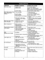
SYMPiuM
POSSIBLE CAUSE(S)
CORRECTIVE ACTION
Motor does not start
1. Defective switch
2. Defective motor
1. Have switch replaced.
2. Have motor replaced/repaired.
NOTE: 1 and 2 must be done t)y a qualified
service technician; Consult Sears service,
3. Low line voltage
3, Correct low line voltage condition,
Motor stalls (resulting in blown 1. Circuit overloaded
fuses or tripped circuit
breakers)
2. Low line voltage
3. Motor overloaded
4. Incorrect fuses on circuit breakers
1, Reduce circuit load
(turn off other appliances).
2. Correct low line voltage conditions,
3. Reduce load on motor,
4. Have correct fuses on circuit breakers
installed.
5. Short circuit in motor; loose
connections or worn insulation
on lead wires
5, Inspect terminals in motor for damaged
insulation and shorted wires and have
them replaced,
Motor starts slowly or fails to
come to full speed
1. Defective motor windings
2. Clogged wood chips
1. Have motor replaced/repaired.
2, Take shallow depth of cut and attach a
shop-vac to exhaust port.
Motor running too hot
!. Motor overloaded
2. Restricted air cimulation due to
dust accumulation
1. Reduce load on motor,
2, Clean dust and restore normal air circulation.
Frequent opening of fuses or
circuit breakers
1. Motor overloaded
1. Reduce load on motor
2. Have correct fuses or circuit breakers
installed.
3. Reduce circuit load
(turn off other appliances).
Snipe
(gouging at end of boards)
1. Dull blades
Uneven depth of cut
1, Blade height not uniform
2. Fuses or circuit breakers do not
have sufficient capacity
3. Circuit overloaded
1. Replace or sharpen blades.
See "Sharpening Blades," page 9.
2. inadequate support of long boards 2. Support long boards.
See "Recommended Accessories," page 15.
3. Uneven feed
3. See "Feeding Workpiece," page 8.
2. Fence not perpendicular
jointer bed
3. Feeding wood too fast
45" cuts inaccurate
to
1. Fence stops not adjusted properly
2. Fence bottom not even with
outfeed table due to wood chips
under fence
1. Adjust blade height.
See "Adjusting Blade Height," page 7.
2. See "Positioning Fence," page 6.
3. Feed wood slower.
1. Adjust fence stops.
See "Positioning Fence.", page 6.
2. Clean wood chips from underside of fence.
Fuzzy grain
Planing wood with high moisture
Remove high moisture content from wood by
drying.
Torn grain
1. Too heavy a cut
2. Blades cutting against grain
3. Dull blades
1. Reduce depth of cut.
2. Feed work along grain.
3. Replace or sharpen blades.
11
NOTES
12
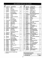
Model 351.217280
Figure
22 - Replacement
Parts Illustration
for Motor
16
\
17
S
1
/
4
7
6
3
2
KEY
NO.
PART NO.
DESCRIPTION
QTY.
1
2856.00
Motor Cover
1
2
3
STD315215
2857.00
6201ZZ Ball Bearing
Armature with Fan
1
1
4
5
STD315205
2858.00
620077 Ball Bearing*
Wavy Washer
1
1
6
7
8
9
10
11
2859.06
STD852005
2860.00
1413.00
STD851005
5383.00
Thread Forming Screw
5ram Lock Washer*
Stator
Strain Relief
5mm Flat Washer*
5-0.8 x 16mm Hex Head Bolt
2
6
1
1
4
4
12
13
14
2861.00
2862.00
2863.00
Brush Cap
Carbon Brush (set of 2)
Brush Holder
2
1
2
15
1838.00
5-0.8 x 10mm Set Screw
2
16
17
2864.00
1474.00
Motor Housing
5mm Serrated Washer
1
1
Standard hardware item available locally
13
Model351.217680
Figure 23 - Replacement
Parts Illustration
for Jointer
41 42
39
38
37
59
4
42
60
61
32
82
30
83
33
19
74
73
\
79
\
80
\
5
4
14
1:
KEY
NO.
PART NO.
DESCRIPTION
1
2
3
4
5
2893.01
4135.00
1553.00
2895.00
0850.00
Base
Foot Pad
6
7
8
9
10
11
9722.OO
0423.00
2892.00
9729.00
2894.00
0361.00
12
13
14
15
16
17
18
19
20
21
22
23
STD851005
9723.00
3499.00
24
26
922994.00
2881.00
3835.00
27
28
2803.00
3855.00
25
29
30
31
32
33
34
35
36
37
38
39
140
41
2891.00
4128.00
2887.00
2886.00
0964.00
STD315205
2885.00
2883.00
6346.00
STD851005
2888.01
2889.00
289O.0O
2880.02
2865.00
2866.00
2898.00
1286.00
0781.00
2896.00
2897.00
2872.00
Cord Clamp
Thread Forming Screw
6-1.0 x 16mm
Socket Head Bolt
7mm Special Washer
Switch
Spring
Thread Forming Screw
Cover
5-0.8 x 8mm
Pan Head Screw
5mm Flat Washer*
7mm Special Washer
Wavy Washer
Blade Guard
Access Cover
Belt
Drive Pulley
6-1.0 x 6mm Set Screw
6200ZZ Ball Bearing*
Cutterheed
Blade Clamp
6-1.0 x 12mm
Socket Pan Head Screw
Blade (set of 2)
Shalt
5-0.8 x 12mm
Flat Head Screw
6-!.0 x 12ram Set Screw
5-0.8 x 10ram
Socket Head Bolt
5ram Lock Washer*
Motor Mounting Plate
Motor Pulley
Motor
Outfeed Table
Fence
V,-20" Square Nut
Scale
Rivet
4-0.7 x 8ram Pan Heed Screw
Indicator
Right Side Slotted Plate
Shoulder Bolt
KEY
NO.
QTY.
PART NO.
DESCRIPTION
43
44
9725.00
2868.00
1993.00
45
1903.00
2
46
47
48
49
5O
51
52
53
54
55
56
57
58
59
6O
61
62
63
64
65
56
67
68
69
70
71
72
73
74
75
76
77
9720.00
STD840508
2873.00
9724.00
2874.00
2870.00
9727.00
2871 .(30
5383.00
2867.00
S'rD852006
2876.00
2875.00
9726.00
2878.01
3267.00
9728.00
6461.00
5223.00
2877.00
0221.00
STD840610
9721.00
2879.00
0781.00
3270.00
3271.00
3272.00
2101.00
2899.01
0351.00
5156.00
Wavy Washer
Trunnion Holder
'/,-20 x W'
Socket Head Bolt
4-0.7 x 10mm
Pan Head Screw
5-0.8 x 10ram Hex Head Bolt
5-0.8mm Hex Nut*
Fence Bracket
6mm Special Washer
Handle
Trunnion
2
2
1
Spring
Plate
5-0.8 x 16mm Hex Head Bolt
1
1
1
Support Nut
6mm LockWasher*
T-Nut
1
6
1
Fence Support
Left Side Slotted Plate
Infeed Table
1
1
1
Bracket
8ram Special Washer
4
4
3CMI-8 Retaining Ring
5-0.8 x 30mm Set Screw
Table Frame
4
1
1
3AMI-10 Retaining Ring
6-1.0ram Hex Nut*
6-1.0 x 30ram Set Screw
1
1
1
78
79
8O
81
82
83
STD851004
4137.00
1
42
4
1
8
18
10
1
1
1
1
1
4
1
1
1
1
1
1
2
2
1
2
8
1
1
4
2
4
4
1
1
1
!
1
4
1
2
3
1
1
3
A
Standa_ hardwam item availablelocally
& NotShown
!412.01
9-73666
16404.OO
16405.00
16303.00
I Recommended
15
IPushBlock
3
1
4
1
3
1
Support Plate
1
4-0.7 x 8ram Pan Heed Screw 1 2
Spring
Elevation Screw
Knob
1
1
1
Thread Forming Screw
Chip Chute
6-1.0 x 10ram Set Screw
2
1
4
4mm Serrated Washer
4ram Flat Washer*
Grommet
Une Cord
2
2
1
1
Push Block(set)
Baffle
1
1
i Thread Forming Screw
Owner's Manual
5
1
Accessories
t,, IHorizontal Roller Stand
a
QTY.
(set)
351.21417
9-22994
In U.S.A. or Canada
for in-home major brand repair service:
Call 24 hours a day, 7 days a week
1-800-4-MY-HOME °_(1-800-469-4663)
Para pedir servicio
de reparaci6n
a domicilio
- 1-800-676-5811
Au Canada pour tout le service - 1-877-LE-FOYER"
For the repair or replacement
(1-877-533-6937)
parts you need:
Call 6 a.m. - 11 p.m. CST, 7 days a week
PartsDirect"
1-800-366-PART
(1-800-366-7278)
www.sears.com/partsdirect
Para ordenar
piezas con entrega a domicilio
- 1-800-659-7084
For the location of a Sears Service Center in your area:
Call 24 hours a day, 7 days a week
1-800-488-1222
To purchase
or inquire about a Sears Maintenance
Agreement:
Call 7 a.m. - 5 p.m. CST, Monday - Saturday
1-800-827-6655