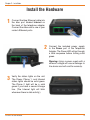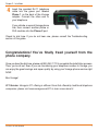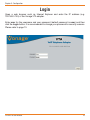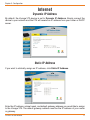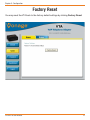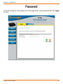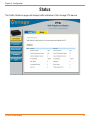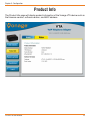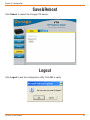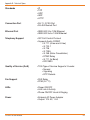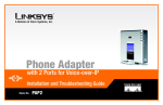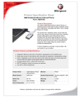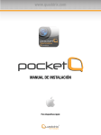
1
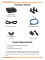
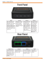
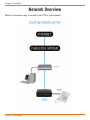
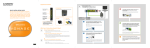
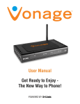
User Manual
Welcome
Unleash Your Phone
For assistance with installation or troubleshooting common problems, please refer to this
User Manual or Quick Installation Guide.
Please visit www.vonage.com/vta to obtain the most up-to-date User Manual and a
description of the latest VTA features.
Activation
If you purchased your Vonage Telephone Adapter from a retail location, you must first
activate your Vonage phone service by visiting www.vonage.com/activate.
After activation, wait 30 minutes before checking for a dial tone.
You will need your MAC ID, which is located on your Vonage Telephone Adapter. The MAC
ID is a combination of twelve letters and numbers. Be sure to enter all of the characters.
After you have chosen a plan and activated, please follow the step-by-step installation
guide to set up your equipment.
D-Link VTA User Manual
Table of Contents
Table of Contents
Chapter 1 - Product Overview...................................................................................... 1
Package Contents................................................................................................ 2
System Requirements.......................................................................................... 2
Front Panel........................................................................................................... 3
Rear Panel............................................................................................................ 3
Chapter 2 - Installation.................................................................................................. 4
Network Overview................................................................................................ 5
Install the Hardware.............................................................................................. 6
Chapter 3 - Configuration............................................................................................. 8
Find IP Address.................................................................................................... 9
Login................................................................................................................... 10
Internet............................................................................................................... 11
Dynamic IP Address...................................................................................... 11
Static IP Address........................................................................................... 11
Factory Reset..................................................................................................... 12
Password............................................................................................................ 13
Status................................................................................................................. 14
Product Info........................................................................................................ 15
Save&Reboot...................................................................................................... 16
Logout................................................................................................................. 16
Appendix A - Troubleshooting.................................................................................... 17
IVR Messages.................................................................................................... 20
Appendix B - Technical Specifications...................................................................... 21
D-Link VTA User Manual
II
Chapter 1 - Product Overview
Chapter 1 - Product Overview
Product Overview
D-Link VTA User Manual
1
Chapter 1 - Product Overview
Package Contents
Vonage VTA
Telephone Adapter
Stand
RJ-11 Phone Cable
Blue Ethernet Cable
Documentation
CD-ROM
Power Adapter
System Requirements
An available Broadband connection
Router
A valid Vonage account*
* If you purchased your Vonage Telephone Adapter from a retail location,
you must first activate your Vonage phone service by visiting www.vonage.
com/activate. After activation, wait 30 minutes before checking for a dial
tone.
D-Link VTA User Manual
Chapter 1 - Product Overview
Front Panel
Power
Internet
Phone 1
Phone 2
When the power light
stops blinking and is a
solid green, this indicates
that your adapter has
started up properly. Note
that both the power light
and the phone light must
be solid in order to make
a phone call.
Solid light indicates
connectivity to your
router or network
- whenever there is
data activity this light
will blink.
Solid light indicates
that phone line 1 is
ready for Vonage
Internet telephone or
FAX calls. A blinking
light indicates that
the phone is in use.
If the LED is blinking
slowly, there is
voicemail on the line.
Solid light indicates
that optional phone
line 2 is ready for
Vonage Internet
telephone or FAX
calls. A blinking
light indicates that
the phone/FAX is
in use. If the LED
is blinking slowly,
there is voicemail
on the line.
Rear Panel
Phone (1 & 2)
Plug your phone into
port #1 and if you’ve
signed up for a second
Vonage phone line, an
optional phone or FAX
machine into phone
port #2.
D-Link VTA User Manual
Internet
Reset
Power
Connect to your
Press the reset button
Plug in the
network using the blue for at least 10 seconds supplied power
Ethernet cable.
to reset the VTA back to adapter.
the default settings.
Chapter 1 - Product Overview
Installation
D-Link VTA User Manual
2
Chapter 2 - Installation
Network Overview
Below is a common way to connect your VTA to your network.
D-Link VTA User Manual
Chapter 2 - Installation
Install the Hardware
1
Connect the blue Ethernet cable into
the blue port labeled Internet on
the back of the telephone adapter.
Connect the other end to one of your
router’s Ethernet ports.
2
Connect the included power supply
to the Power port of the Telephone
Adapter. The Power LED will go through
a blink sequence before turning solid
green.
Warning: Using a power supply with a
different voltage will cause damage to
the device and will void the warranty.
3
Verify the status lights on the unit.
The Power, Phone 1, and Internet
status lights should be solid green.
The Phone 2 light will be a solid
green if you have a second Vonage
line. (The Internet light will blink
whenever there is data activity.)
D-Link VTA User Manual
Chapter 2 - Installation
4
Insert the provided RJ-11 telephone
cable into the green port labeled
Phone 1 on the back of the Vonage
adapter. Connect the other end to
your telephone.
If you activate a second Vonage phone
line, then connect another phone or
FAX machine into the Phone 2 port.
Check for dial tone. If you do not hear one, please consult the Troubleshooting
section of this guide.
Congratulations! You’ve finally freed yourself from the
phone company.
Once you hear the dial tone, please call 800-342-1791 to complete the installation process.
Then, you’re all set. Even if you are transferring your telephone number to Vonage, you
can enjoy the great savings and super quality by using your Vonage phone service right
NOW.
Bon Vonage!
911 Service: Vonage’s 911 offering is different from that offered by traditional telephone
companies; please visit www.vonage.com/911 to learn more about it.
D-Link VTA User Manual
Chapter 3 - Configuration
Chapter 3 - Configuration
Configuration
D-Link VTA User Manual
3
Chapter 3 - Configuration
Find IP Address
The VTA telephone adapter has a built-in configuration utility. To access this utility, you need
to obtain the IP address of the VTA. By default, the VTA telephone adapter automatically
obtains an IP address from your DHCP enabled router or DHCP server. If you do not
have DHCP enabled, the IP address will automatically be set to 192.168.15.254. If you
do have DHCP disabled, you must use a 192.168.15.x network or statically assign the
IP address of a computer to 192.168.15.x (where x is between 1 and 253). You can then
connect to the configuration utility of the VTA and change its IP address to an available
IP address of your network. You will need to change your computer back to the original
IP address.
To find the IP address, log into your router or DHCP server and locate the DHCP table
(reference the User Manual for your router or DHCP server as necessary). The table
will display all of your network clients (using DHCP) that are connected. Search for the
Vonage VTA’s MAC address in the table and the IP address will be listed next to it. The
MAC address is on the bottom of the Vonage VTA device.
Note: The terms MAC Address and MAC ID are used interchangeably.
D-Link VTA User Manual
Chapter 3 - Configuration
Login
Open a web browser such as Internet Explorer and enter the IP address (e.g.
192.168.0.100) of the Vonage VTA adapter.
Enter user for the username and your password (default password is user) and then
click the Login button. It is recommended to change your password for security reasons.
Please refer to page 13.
D-Link VTA User Manual
10
Chapter 3 - Configuration
Internet
Dynamic IP Address
By default, the Vonage VTA device is set to Dynamic IP Address. Simply connect the
device to your network and the VTA will receive an IP address from your router or DHCP
server.
Static IP Address
If you want to statically assign an IP address, click Static IP Address.
Enter the IP address, subnet mask, and default gateway address you would like to assign
to the Vonage VTA. The default gateway address must be the IP address of your router
or gateway.
D-Link VTA User Manual
11
Chapter 3 - Configuration
Factory Reset
You may reset the VTA back to the factory default settings by clicking Factory Reset.
D-Link VTA User Manual
12
Chapter 3 - Configuration
Password
You may change the User password on this page. Enter a new password and click Apply
to save.
D-Link VTA User Manual
13
Chapter 3 - Configuration
Status
The Traffic Statistics page will display traffic statistics of the Vonage VTA device.
D-Link VTA User Manual
14
Chapter 3 - Configuration
Product Info
The Product Info page will display product information of the Vonage VTA device such as
the firmware version, software version, and MAC address.
D-Link VTA User Manual
15
Chapter 3 - Configuration
Save&Reboot
Click Reboot to restart the Vonage VTA device.
Logout
Click Logout to exit the configuration utility. Click OK to verify.
D-Link VTA User Manual
16
Appendix A - Troubleshooting
Appendix A - Troubleshooting
Troubleshooting
D-Link VTA User Manual
A
17
Appendix A - Troubleshooting
•Many installation issues, such as no dial tone on your telephone or no internet connection
on your computer, can be resolved by resetting all the equipment. First power down in
this order:
1.Computer (shut down properly, it is not necessary to disconnect power to your
computer)
2.VTA (unplug power cord from back of device)
3.Router (unplug power cord from back of device)
4.DSL or Cable Modem (unplug power cord from back of device)
Wait at least 30 seconds. Confirm that all the network cables are firmly snapped into the
jacks on all the devices. Then, one device at a time, plug the power back in snugly in this
order:
1. DSL or Cable Modem
Wait for the lights to come back on for power and external network connection before
continuing. Connecting back up to the Internet Service Provider may take several
minutes.
2. Router
Wait for the lights to come back on for power and status before continuing. Wait at least
30 seconds.
3. VTA
Wait for the power and phone lights to be a solid green. (The Internet light will blink
whenever there is data activity.) At this point, you should have dial tone.
4. Computer
• If you are transferring your phone number from your current phone company to Vonage,
you will be assigned a temporary Vonage phone number. Until the transfer has completed,
most people calling your phone number will ring your old line. They would need to call
the temporary phone number to ring your Vonage phone. However, Vonage customers
calling either your current phone number or the temporary phone number will ring your
Vonage phone. Note: You will receive email notification from Vonage when the phone
number transfer has completed. The temporary number will then be terminated.
D-Link VTA User Manual
18
Appendix A - Troubleshooting
During the startup process you may notice that the Power light on the front of the VTA is
blinking. These blinks indicate that the VTA is booting up with Vonage service. You may
find the following blink sequences helpful to you:
1 blink (blink, pause, repeat)
2 blinks (2 blinks, pause, repeat)
3 blinks (3 blinks, pause, repeat)
4 blinks (4 blinks, pause, repeat)
Rapid Blinking
Solid
D-Link VTA User Manual
VTA is powering up
VTA is obtaining an IP address
VTA is obtaining configuration from Vonage
VTA is registering with Vonage
Downloading/upgrading firmware (do not power down)
Startup process is complete
19
Appendix A - Troubleshooting
IVR Messages
Your Vonage telephone adapter comes equipped with some pre-programmed voice
messages to help troubleshoot issues with your device. The errors are listed below and
will automatically be played in the case there is an error when you lift the receiver of a
phone attached to your device.
The following IVR messages are played on the Vonage VTA:
1. “The Vonage device has no network connectivity.”
You will hear this message when your phone line is properly set up and ready for calls,
but your Internet connection is down. Check to see if you are able to access the Internet
from your computer that is connected to your router. If not, check with your Internet
Service Provider to determine if they are having connection issues in your area.
2. “The Vonage device has no network settings.”
You will hear this message when your phone line is properly set up, but there are
insufficient or incorrect network settings. If you have set a static IP address, verify that
the Default Gateway and the DNS server address is the IP address of your router (refer
to page 11). Network issues may be resolved by resetting your equipment. Refer to page
19 for details.
3. “The Vonage device cannot contact the Vonage network.”
You will hear this message when your phone line is properly set up but cannot connect to
the Vonage network. This may be due to a change to the network settings. For example
you may be experiencing firewall issues. Check if your network setup has changed since
you last connected to the Vonage network.
4. “This telephone line cannot register to the Vonage network.”
You will hear this message when your phone line is properly set up and can connect to
the Vonage network, but cannot register to Vonage. Please verify that your router in front
of the VTA device is not blocking any incoming traffic. If SPI is enabled on the router,
disable it.
5. “Your phone maybe plugged into the incorrect phone port. Please try the other
port. If you believe that you are connected to the correct phone port, please log
into your web account to check the status of your service.”
You will hear this message when your telephone is connected into a phone port that is not
set up for Vonage service. If you are plugged into Port 2, try moving to Port 1. In addition,
you can check the status of your Vonage service by logging into your web account.
For more troubleshooting tips, visit www.vonage.com/help.
D-Link VTA User Manual
20
Appendix B - Technical Specifications
Appendix B - Technical Specifications
Technical Specs
D-Link VTA User Manual
B
21
Appendix B - Technical Specs
Standards
• IP
• TCP
• UDP
• ARP
• HTTP
Connection Port
• RJ-11, 2 FXS Port
• RJ-45 Ethernet Port
Ethernet Port
• IEEE 802.3 for 10M Ethernet
• IEEE 802.3u for 100M Ethernet
Telephony Support
• SIP Call Control Protocol
• Supports Audio CODEC
• G.711 (A-law and U-law)
• G.723.1
• G.726
• G.729A
• G.168 (Echo Cancellation)
• DTMF Relay
• G.711 (In Band)
• RFC2833
Quality of Service (QoS) • TOS-Type of Service Supports 3 Levels:
• Normal
• Signaling
• RTP Packets
Fax Support
• FAX Relay
• PCM (G.711)
LEDs
• Power ON/OFF
• LAN Link & Activity
• Phone ON/OFF Hook & Ringing
Power
• External AC Power Adapter
• Output: 12V AC, 1.2A
D-Link VTA User Manual
22
Appendix B - Technical Specs
Temperature
• Operating:0°C to 40°C
• Storing: -10°C to 55°C
Humidity
• 5%-95% Non-Condensing
Certifications • EMC: FCC Class B, CE Class B,
CSA international, CB
Dimensions
• 90mm x 82.46mm x 31mm (WxDxH)
Warranty
• 1 Year Limited Warranty
Vonage USA
Version 1.2
July 14, 2006
Copyright ©2006 D-Link Corporation/D-Link Systems, Inc. All rights reserved. D-Link and the D-Link
logo are registered trademarks of D-Link Corporation or its subsidiaries in the United States and other
countries. Other trademarks are the property of their respective owners.
D-Link VTA User Manual
23