1
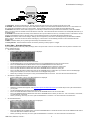
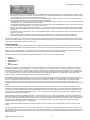
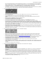
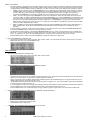
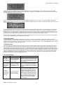
Web Mountain Technologies UPB Timer (TIM-01) Version 3 Revised May 10, 2007. For the latest revision, see www.webmtn.com/support/docs/TIM-01.pdf Web Mountain Technologies Table of Contents 1 Summary 2 How it works 3 Timer Buttons 4 Quick Start – Scheduled Programs 5 Quick Start – Countdown Timer 6 UPB Operations 7 On and Off Programs 8 Triggers 9 How to Program the UPB Timer 10 Immediate Run 11 Reset 12 Emergency Mode 13 Random Timers 14 Trouble Shooting 15 Support 16 Warranty 17 Other UPB Products UPB Timer (TIM-01) Version 3 1 1 1 2 3 4 5 5 5 11 11 12 12 12 13 14 14 User Manual for the UPB Timer (TIM-01) Version 3 1 Summary The TIM-01 UPB Timer is one of the most advanced standalone timer-controllers on the market today. It can easily be programmed to control individual UPB devices or UPB scenes either manually or on a timed basis. The Timer can control up to 99 programs and with the Timer’s buttons, you can manually control 4 scenes. Using either the timed function or the manual buttons, you can have your outside lights as well as inside lights and appliances go on and off at your command or at preset times to give your home a lived-in look while you are away. You can program your UPB modules to go on and off at the same time every day or you can set up programs to operate only on selected days of the week. There is also a “Random” mode which automatically varies your programmed time each day so your home doesn’t look like it’s controlled by a timer. You can keep the TIM-01 UPB Timer by your bedside to manually turn off your child’s radio or night light or to dim your bedside lamp. You can turn on ALL lights connected to Lamp Modules and Wall Switch Modules with the touch of a button if you hear a suspicious noise at night. You can even turn off everything in the system with one button. In addition to offering the ability to automatically control normally scheduled events, Version 3 of the TIM-01 also allows you to turn any UPB module in your network into a count-down timer. Turn a switch on and the TIM-01 can turn it off for you automatically at a later time. The TIM-01 can handle up to 99 separate triggers, each of which can be used to enable a standard UPB module to operate as a delay timer. Another great feature of the TIM-01 is the ability to turn scheduled events on and off easily. If you’re planning a late night patio party and you don’t want your outdoor lights to automatically go off just as the party starts hopping, you can easily suspend the scheduled program that would normally turn the outdoor lights off. In order to give you piece of mind while you’re away from home, the timer can be set up to turn interior lights and appliances on and off at random, but logical, times to make your house appear to be occupied even when you are gone for a night, a week or a season. The Timer maintains the current date, it automatically adjusts for daylight savings time and leap year, it can control events based on local sunset and sunrise and it combines battery backup with flash memory to insure the correct operation of all functions after power outages. With the ability to synchronize its time to the national utility grid for accurate time-keeping, the TIM-01 truly allows you to “set it and forget it”. Before you begin Keep in mind that your UPB System can be programmed to turn lamps and appliances on or off the instant you press the appropriate button. When controlling appliances, however, there can be some unexpected consequences. For example, an empty coffee pot can be remotely turned on. If that should happen, your coffee pot may be damaged from overheating. If an electric heater is turned on by remote control while clothing just happens to be draped over it, a fire could result. Therefore, do not use UPB modules with high power heating devices such as portable heaters. Always be aware of what appliance you are turning on or off so that potentially dangerous situations will not occur. What it does The TIM-01 UPB Timer plugs into any AC outlet in your home and acts much like a conventional appliance timer, but with many additional capabilities: • • • • • • • • • • • • • • • • • • • Control a single UPB device or complete scenes involving many UPB modules Define up to 99 separate programs Turn up to 99 other UPB modules in delay (count-down) timers Digital clock and calendar display Automatically adjusts for Daylight Saving Time (2007 rules) and leap years Includes an Astronomical Clock for sunrise and sunset programs Vacation mode to make house look occupied Random option to avoid the appearance that lights are on a timer Synchronization with the national power grid for accurate time-keeping Suspend or enable scheduled programs easily Allows manual operation of all programs Instant manual operation of up to 4 programs Non-timed programs that can only be run manually Can be set up to repeat all actions for enhanced reliability Emergency button(s) to light up the house The MENU functions can be locked out to avoid accidental changes in settings Can be used as a PIM (Program Interface Module) to enable connection between a PC and the UPB network Battery backup Non-volatile storage to maintain all settings during power outages 2 How it works The TIM-01 UPB Timer plugs into any AC outlet in your home and transmits digitally encoded signals over your house wiring instantly or at the times you set. These signals are received by the UPB Modules in your home. You can plug a lamp into a UPB Lamp Module, an appliance such as a TV, stereo or coffee pot into a UPB Appliance Module and replace important indoor or outdoor security lights with UPB Wall Dimmers. The TIM-01 will enable you to turn these devices on and off at scheduled times and/or turn each module into a separate delay or count-down timer. Introduction 3 Timer Buttons Let’s quickly review the functions of each part of the Timer. Referring to the diagram below you will see that on the face of the Timer are an LCD readout, 7 buttons and an indicator light. Web Mountain Technologies Quick Tour 1. LCD Readout. All output is displayed here. Normally this area will show the time of day, the date and the day of the week. 2. UP/DOWN. These two buttons are mainly used to select different values for the various fields and attributes that can be set. These buttons can also operate as Immediate Run buttons or as Panic buttons. See the following sections for more details about these alternative uses. 3. FUNCTION. This button is used to select a program to run manually, to see the current day’s sunset and sunrise times, to lock out the MENU button or to put the Timer into Vacation mode or PIM mode or Host mode. This button will also return the Timer to its normal (RUN) state from any of the Setup screens. 4. LEFT/RIGHT. These two buttons are mainly used to select the next or previous field to be set in any of the Setup screens. These buttons can also operate as Immediate Run buttons or as Panic buttons. See the following sections for more details about these alternative uses. 5. ENTER. This button is used to commit settings. Settings can be changed at any time, but the new settings will only be saved after the ENTER button is pushed. This button can also be used as an Emergency or Panic button. See the following sections for more information about this alternative use. 6. MENU. This button allows you to cycle through various Setup and Information screens. 7. Activity Indicator. This LED will blink whenever the Timer is performing a saved program or a trigger. 4 Quick Start – Scheduled Programs If you’ve already defined a UPB Link (scene) and simply want to set up the Timer to turn it on at a certain time of the day and turn it off later in the evening, follow these steps: • Set the Time and Date o Push the MENU button until the SETTIM screen is displayed. o o o o o o o o • Set Latitude, Longitude and Time Zone o Push the MENU button until the LAT LONG ZONE screen is displayed. o o o o o • Use the UP/DOWN buttons to select the correct hour. Use the RIGHT button to go to the minute field and then use the UP/DOWN buttons to select the correct minute. Move to the AM/PM field with the RIGHT button and use the UP/DOWN buttons to select AM or PM. Move to the month field with the RIGHT button and use the UP/DOWN buttons to select the current month. Move to the date field with the RIGHT button and use the UP/DOWN buttons to select the current date. Move to the year field with the RIGHT button and use the UP/DOWN buttons to select the current year. Move to the DST field with the RIGHT button and use the UP/DOWN buttons to select DSTY if you want the Timer to handle Daylight Savings Time or DSTN if you are in an area that does not use Daylight Savings Time. Review all your settings, and if they are correct, push the ENTER button to save them. The Timer will revert to the RUN screen. Determine your latitude and longitude, using http://www.zipinfo.com/search/zipcode.htm (or a similar site) to look up the values based on your zip code. Use the UP/DOWN buttons to set the correct value for LAT. Move to the LONG field with the RIGHT button and use the UP/DOWN buttons to set the correct LONG. Move to the ZONE field with the RIGHT button and use the UP/DOWN buttons to select your time zone. Use -5 for Eastern, -6 for Central, 7 for Mountain and -8 for Pacific. Review your settings, and if they are correct, push the ENTER button to save them. The Timer will revert to the RUN screen. Set the UPB Network ID o Push the MENU button until the TRY/NID screen is displayed. o o Move to the NID field with the RIGHT button and use the UP/DOWN buttons to set the NID to be the same as the UPB Network ID used for all the other UPB devices installed in this home. Review your settings, and if they are correct, push the ENTER button to save them. The Timer will revert to the RUN screen. UPB Timer (TIM-01) Version 3 2 TIM-01 User Manual • Set up a program to Activate the Link Push the MENU button until the SET screen is displayed. o o o o o o o o o • Set up a program to Deactivate the Link o Push the MENU button until the SET screen is displayed. o o o o o o o o o • Use the RIGHT button to move to the hour field. The NEW field will automatically change to the next available program number. If this is the first time you have set up any programs, the field will change to P01. Use the UP/DOWN buttons to select the hour at which you want the Link you have already set up to be activated. Use the RIGHT button to move to the minute field and use the UP/DOWN buttons to select the proper value for minutes. Use the RIGHT button to move to the AM/PM field and use the UP/DOWN buttons to select AM or PM. Use the RIGHT button to move to the Link number field and use the UP/DOWN buttons to select the Link number that has already been set up and that you want to have activated by this timer program. Use the RIGHT button to skip the next field (which has an “A” in it), because we already know that the program we are setting up is meant to Activate (turn on) the Link in question. Use the UP/DOWN buttons on the next field to select N or R. Use N for programs that you want to run at exactly the time you have set up. Use R for programs that you would like to be randomly varied by up to 30 minutes in either direction from the time you have set up. Use the RIGHT button to move to the “S” field. Use the UP/DOWN arrows to either select the program to run on Sunday or to keep it from running on Sunday. If the “S” is showing, the program will run on Sunday. If there is a dash in place of the “S”, the program will not run on Sunday. Use the RIGHT button to move to each day of the week, selecting whether or not to run this program on each day of the week according to the directions laid out in the previous step. Review all your settings, and if they are correct, push the ENTER button to save them. The Timer will revert to the RUN screen. Use the RIGHT button to move to the hour field. The NEW field will automatically change to the next available program number. Because you already set up a program in the previous step, the value you see here will most likely be P02. Use the UP/DOWN buttons to select the hour at which you want the Link you have already set up to be Deactivated (turned off). Use the RIGHT button to move to the minute field and use the UP/DOWN buttons to select the proper value for minutes. Use the RIGHT button to move to the AM/PM field and use the UP/DOWN buttons to select AM or PM. Use the RIGHT button to move to the Link number field and use the UP/DOWN buttons to select the Link number that has already been set up and that you want to have deactivated by this timer program. Use the RIGHT button to move to the next field and use the UP or DOWN button to change the value to “D” because we want to Deactivate the Link. Use the RIGHT button to move to the next field and use the UP/DOWN buttons to select N or R. Use N for programs that you want to run at exactly the time you have set up. Use R for programs that you would like to be randomly varied by up to 30 minutes in either direction from the time you have set up. If you select R for both the Activation program and the Deactivation program for the same Link, make sure the two programs are more than an hour apart to avoid the possibility that the Link will not be Deactivated as you expect. Use the RIGHT button to move to the “S” field. Use the UP/DOWN arrows to either select the program to run on Sunday or to keep it from running on Sunday. If the “S” is showing, the program will run on Sunday. If there is a dash in place of the “S”, the program will not run on Sunday. Use the RIGHT button to move to each day of the week, selecting whether or not to run this program on each day of the week according to the directions laid out in the previous step. Review all your settings, and if they are correct, push the ENTER button to save them. The Timer will revert to the RUN screen. Your Timer is now set up to Activate the Link at the time you’ve selected and then to Deactivate it later according to your settings. 5 Quick Start – Countdown Timer A common use for the Countdown Timer capability is to automatically turn off a bathroom fan a certain amount of time after it has been turned on. The first step in implementing this capability is to install a UPB dimmer or relay switch to control the fan. If you are installing a dimmer, use UPStart to make sure the switch is set for on/off operation only. Trying to reduce the speed of any kind of fan with a UPB dimmer is not a supported function. In UPStart, assign a Link (we’ll use L040 as an example) to be transmitted when the top rocker is pressed. Make sure this same Link is in the receive table as well and is setup to turn the fan on and off. Assign another Link (we’ll use L044) to the receive table of the switch. Use UPStart to make sure the switch rocker has been Transmit Enabled (see the Options tab). DO NOT use Link241 for any button or rocker that is Transmit Enabled. Link241 is reserved as an internal link in many UPB switches. Assuming you have already set the date/time, latitude, longitude, time zone and UPB Network ID (see the previous section) follow these steps to quickly turn the UPB switch into a countdown timer: • Set up a Trigger to watch for a UPB Link, wait a defined amount of time, then issue another Link: o Push the MENU button until the SET screen is displayed. o 3 Use the UP/DOWN buttons to change the first field from a P to a T. Notice that the screen changes as follows: UPB Timer (TIM-01) Version 3 Web Mountain Technologies o o o o o o o o Use the RIGHT button to move to the first Link field. The NEW field will automatically change to the next available trigger number. If this is the first time you have set up any triggers, the field will change to T01. Use the UP/DOWN buttons to select the Link (in our example L040) that will indicate to the timer that a count-down operation is to begin. Use the RIGHT button to move to the next field and use the UP/DOWN buttons to select A, indicating that the count-down operation will begin only if the Timer sees an Activate L040 UPB command on the powerline. Use the RIGHT button to move to the hour field and use the UP/DOWN buttons to select how many hours you want to delay before sending out a UPB action. In our example let’s leave this value at zero. Use the RIGHT button twice to skip over the h field and get to the minute field. Use the UP/DOWN buttons to select the number of minutes to wait before sending out a UPB action. Let’s use 15 in our example. Use the RIGHT button to skip the next field (which has an “L” in it), because we know we want to issue a UPB Link after the delay has been achieved. Use the UP/DOWN buttons on the next field to select the number of the Link you want to send out after the delay (our example uses L044). Use the RIGHT button to move to the “A” field. Use the UP/DOWN arrows to select D here because we want to send an L044 Deactivate to actually turn the fan off. Leave the last field set to N, because we want this trigger to be active all the time, not just when the timer is left in Vacation mode. Review all your settings, and if they are correct, push the ENTER button to save them. The Timer will revert to the RUN screen. Your Timer is now set up to react whenever it sees an L040 Activate on the powerline. After 15 minutes the timer will send out an L044 Deactivate which will cause the fan switch to turn the fan off. If the top rocker is pushed again before the 15 minutes elapse, the timer will start a new countdown timer, thereby delaying the time at which the fan will turn off. 6 UPB Operations Universal Powerline Bus (UPB) is a state of the art home automation control system that uses the existing AC powerline within your home to carry control signals. Using the existing AC powerline means that you, the user, don’t need to add any additional wiring to your home in order to use UPB. However, UPB is a very sophisticated, very flexible, and very powerful system. Due to the power of the system, users may find the system slightly confusing and difficult to setup at first, but after a little experience, the logic of the system’s design becomes evident. All UPB devices have to be set up with some fundamental information. The items that can be configured include: • • • • • • Unit ID Network ID Network Password Network Name Links Other information UPB devices all work on a concept called “Links”. A Link is very similar to a home automation scene, a term used in the lighting control industry to describe specific lighting events. For example, you can create a “viewing scene” for your home theater or an “entertainment scene” in your dining room. When the Link (or scene) is activated, a UPB command is transmitted on the powerline and the appropriate lights will respond by brightening or dimming to the proper level. No central controller is required to make this happen. Most UPB devices can be included in up to 16 different Links. “Links” is a UPB term used to describe a channel of communication linking transmitters and receivers in a lighting system. Because of the Link structure of UPB, one powerline command can affect up to 250 devices simultaneously. Each UPB device must be programmed with a Unit ID. The unit ID will have a value between 1 and 250. Units out of the box from the factory will have a Unit ID assigned that equals the manufacturer’s product ID. For example, all Web Mountain appliance modules out of the box will have a Unit ID of 5. Another example: all Web Mountain lamp modules out of the box will have a Unit ID of 1. In normal operation, a Unit ID will have little meaning, as the device will be used mainly to respond to Links. However, in the event that the user wants to program a specific device with configurations other than the default, the available programming tools (to be discussed later), will need unique Unit IDs. We will discuss programming shortly. Each UPB product must also have a Network ID. When control signals are sent out on the powerline, part of the signal is the Network ID. Only devices that have that specific Network ID will respond to the signal and take the appropriate action. In real life, it is expected that a Network ID will correspond to one home. Adjacent homes should use different Network IDs, in order to prevent signals in one home from controlling devices in the house next door. The appropriate range for Network IDs is 1 – 250. The Network ID is the critical item that must be known in order for the TIM-01 UPB Timer to operate a given UPB installation. Each UPB product must also have a Network Password. In order to program a device or change its programming, you must know the appropriate Network ID, and then the appropriate Network Password. If two homes side by side have the same Network ID, but different passwords, then users in both homes will be able to control devices in each home, but they can’t program devices in the other home, only their own. Again, this highlights the importance of using different Network IDs for adjacent homes. The Network Password is a four character alpha-numeric password, with each character allowed to be in the range of 0 – F (hexadecimal). While the network name has little importance, it is a means of determining which network is being used, especially in the case of a multi-network system. UPB devices are also programmed for a room name, and a device name. The room name is important within various controller environments, as it organizes all devices according to rooms. However, it is not important for manual setup. The device name merely gives the user the ability to name a device so that it is easily understood what the device does. For example, rather than being named New Lamp Module, the module can be named Bedside Table Lamp. UPB Timer (TIM-01) Version 3 4 TIM-01 User Manual The only way the TIM-01 Timer can control UPB devices is by issuing Link commands, therefore every device to be controlled must be associated with one or more Links and the behavior of each of those Links must be defined for each device to be controlled by that Link. UPB devices and Links cannot be adequately set up by manual means – you must use the Web Mountain NetPlace server, the free download program UPStart or some other programming tool to set up the modules and Links. See www.webmtn.com for more information about UPB programming tools or to download UPStart. Once Links have been defined, they can either be Activated or Deactivated. Activating a Link means to set all UPB modules associated with that Link to the values defined for the Link. Deactivating a Link means to turn off all UPB modules associated with that Link. Although it is possible to set up Links to specifically turn devices off, the easiest way to implement turning all devices associated with a Link off is to Deactivate the Link. 7 On and Off Programs Every circuit or scene to be controlled automatically by the Timer needs to have two programs defined – one to turn the circuit or scene on and one to turn it off. The easiest way to do this is to set up one program to Activate a Link and another program to Deactivate the same Link. Another way to do this is to define a Link that turns all appropriate devices on to desired levels, then define another Link that turns all these same devices off. Then a program would be defined to Activate the first Link, and another program would be defined to Activate the second Link. In this case, Activating the second Link turns all devices off because that is how the Link is defined. 8 Triggers Triggers are a very powerful component of the Web Mountain Timer. Triggers can be used to turn any UPB device into a delay, or count-down, timer. Common applications for this capability are bathroom fans, closet lights, driveway lights, secure entry applications and the support of motion detectors. In addition to converting UPB devices into delay timers, triggers can be used to suspend and enable scheduled programs. You can use this feature to set up a UPB button that will turn off scheduled programs and another UPB button that will turn them back on again. One possible use for this capability would be to use it to turn off all landscape lighting programs during periods when the homeowners are away from home. 9 How to Program the TIM-01 UPB Timer GENERAL PROGRAMMING NOTES 1. Use the MENU button to cycle through all screens (except RUN PROGRAM, SUNRISE SUNSET, CONTRAST, VACATION MODE, PIM MODE, HOST MODE, LOCK MENU and the 2007 DST/AC SYNCH information screen). To get out of a mode without making any changes, use the MENU button to cycle back to RUN mode or use the FUNCTION button to return immediately to RUN mode. No changes will be made if the MENU or FUNCTION buttons are pressed before the ENTER button is selected to save changes. 2. Use the FUNCTION button to cycle from RUN to RUN PROGRAM to SUNRISE SUNSET to CONTRAST to VACATION MODE to PIM MODE to HOST MODE to LOCK MENU to 2007 DST/AC SYNCH then back to RUN. To get out of one of these modes without making any changes, use the FUNCTION button to cycle back to RUN mode or use the MENU button to return immediately to RUN mode. No changes will be made if the MENU or FUNCTION buttons are pressed before the ENTER button is selected to save changes. 3. Clicking any button that is not defined in a given mode will result in no changes. 4. On any screen (except RUN, VACATION MODE, PIM MODE and HOST MODE) if the ENTER button is not clicked within 1 minute, the Timer will drop out to the RUN screen, and no changes will be saved. 5. The MENU button is the primary setting button - the FUNCTION button is used only to return to RUN mode, to run programs manually, to see current sunrise/sunset timers, to change the screen’s contrast, to put the Timer into Vacation, PIM or HOST mode, to lock the MENU button or to see the status of the 2007 DST and AC SYNCH settings. 6. If UP/DOWN buttons are held for longer than 1 second, they will scroll the intended function rapidly. 7. The MENU button will scroll through the various modes in the following order: RUN, SET, DELETE, SET TIME, SET LAT/LONG/ZONE, SET TRY/NID/EMERGENCY, RUN. 8. The FUNCTION button will scroll from RUN to RUN PROGRAM to SUNRISE SUNSET to CONTRAST to VACATION MODE to PIM MODE to HOST MODE to LOCK MENU to 2007 DST/AC SYNCH then back to RUN in that order. 9. The Timer’s LCD screen is backlit for a period of one minute any time a button is pressed. If no other button is pushed within a one minute window, the backlight will turn off after one minute. The only exception to this is the PIM MODE screen. If you hit ENTER to put the Timer into PIM mode, the backlight is extinguished immediately and will not light up again for any button push except for the ENTER button. When the ENTER button is pushed to take the Timer out of PIM mode, the backlight appears immediately. 10. Programs and triggers can be configured to cause a Link to Blink a UPB device. Extreme care should be taken when using this feature. Attempting to blink a heavy inductive load could result in tripped circuit breakers and possible damage to the appliance itself. Even defining an action to cause lights to blink on and off will shorten the life of the lighting element. Please use the Blink feature only where there is a compelling reason to do so. MENU MODES: • RUN (Push MENU button until RUN shows): o This is the normal display. It shows current time, date, and day of week. • SET (Push MENU button until SET appears): 5 UPB Timer (TIM-01) Version 3 Web Mountain Technologies o o o o o o o o o o o o o o • Setting Up Sunset and Sunrise Based Programs: o • You can set up Sunset or Sunrise timers, or timers that vary from Sunset or Sunrise by a certain amount. You get to this variation of the SETP screen by cycling through 6PM (to get to sunSET) or cycling through 6AM (to get to sunRISe). When SET (or RIS) is flashing, use the RIGHT button to get to the + or – sign (default is +). It will flash, then you can cycle between + and – using the UP and DOWN buttons. Push RIGHT again, and the offset value will flash (default is 000). This is how many minutes before (-) or after (+) sunSET (or sunRISe) that you want the program to run. Use the UP and DOWN buttons to cycle through the number of minutes you want, then use the RIGHT button to cycle to the Link field. Refer to the previous section for information on setting all other program fields. Setting Up a Program for Manual Operation Only: o • There are 15 fields that can be set on this screen: program or trigger, program or trigger number, hour, minute, AM/PM, link number, Activate/Blink/Deactivate, Normal/Random/Vacation and a single letter field for each day of the week. The very first field by default is a P for Program. By using the UP/DOWN buttons you can toggle between T (for Trigger) and P. See instructions for setting up triggers later in this section. If the first field is P, when you first arrive at this screen you will see NEW in the program number field. The other defaults will be shown as: 12:00PM; L001; A (for Activate); N (for Normal); SMTWTFS for every day of the week. Use the RIGHT and LEFT buttons to select between program, hour, minute, AM/PM, Link, A (Activate) or B (Blink) or D (Deactivate), N (Normal) or R (Random) or V (Vacation), S, M, T, W, T, F and S. A field flashes when it is active for selection. If any of the days have been deselected, there will be a flashing cursor over a dash at that location. If you want to view or change an existing program, use UP/DOWN while the cursor is in the program number field to select an existing program for editing (see a later section for more information about modifying or viewing an existing program). To set up a new program, use the RIGHT button to cycle to the hour field, at which point the Timer will fill in the next available program (Pxx) in the program number field. To set the hour you want the program to run, use UP/DOWN to cycle through hours. AM and PM will change as you cycle through 12. After 6PM, the next setting will be SET (for Sunset), then 7PM. After 6AM, the next setting will be RIS (for sunrise), then 7AM. After 12 PM, the next setting will be NONE (See the following section for details on setting Sunset and Sunrise based times. NONE will be used to setup a program to be run manually – i.e. a program that is not time based). For minutes, use UP/DOWN to select the correct value. For Link, use UP/DOWN to select the appropriate UPB Link (1 – 250) to be either activated or deactivated (see the prior section on UPB Operations for more information). For A, B or D, use UP/DOWN to select between Activate, Blink and Deactivate (see the prior section on UPB Operations for more information). If you select A, the UPB Link you have defined will be activated at the set time. If you select B, the Link will cause associated devices to blink at the set time. If you select D, the UPB Link will be deactivated at the set time. NOTE: please exercise extreme care when considering whether or not to cause a Link to Blink. See the caution in the GENERAL PROGRAMMING NOTES section of this document. For N, R or V, use UP/DOWN to select Normal, Random or Vacation. Normal means the program will be executed at the set time on each day that is selected in the day fields. Random will cause the Timer to vary the time of execution by up to 30 minutes in either direction from the set time. Vacation defines a program that will ONLY be run when the Timer is left in the Vacation mode. (See more on Vacation mode in a later section.) For each of the day fields, the initial will flash if that day has been selected. If the day has been deselected, there will be a flashing cursor over a dash at that location. Use the UP/DOWN buttons to cycle between selecting a day or deselecting it. Each timer event can be set to run on any combination of days in the week. When you have set each field as desired, press ENTER to commit all settings and go back to RUN. If the MENU or FUNCTION button is selected without clicking ENTER, or if a minute goes by without clicking ENTER, the settings will be annulled and the program number will go back into the free pool. If any non functioning button is pressed during setup nothing will happen. You can set up programs that will never be activated at a set time. You would do this if there are certain functions you want to be able to control from the RUNPROG screen or from the Immediate Run buttons but you do not want those functions ever executed automatically by the Timer. You get to this variation of the SETP screen by cycling through 12PM to get to NONE. When NONE is flashing, use the RIGHT button to get to the Link field. Refer to the previous section for information on setting all other program fields. Triggers for delay timers: o You get to this screen by pushing the MENU button until you get to the SET screen, then pushing UP/DOWN to change the first field from P to T. UPB Timer (TIM-01) Version 3 6 TIM-01 User Manual o o o o o o o o o o o o • Triggers to suspend or enable programs: o o o o o o • o o o o 7 There are 10 fields that can be set on this screen: program or trigger, program or trigger number, triggering Link, triggering activity, hours/minutes value, h or m, minutes/seconds value, L or P, program number and ENAB/SUSP/NEXT. If you select P instead of L on the lower line, that means you want the Timer to either SUSPend or ENABle a program or you want to skip the NEXT scheduled occurrence of the program. Use the RIGHT button to go to the next field and use UP/DOWN to choose the Program number for the Program you want to suspend, enable or skip. The next field can be ENAB, SUSP or NEXT. If you want to suspend a program indefinitely, select SUSP here. If you want to enable a program that had been suspended, select ENAB here. If you want to skip only the next scheduled occurrence of the program, select NEXT here. When you have set each field as desired, press ENTER to commit all settings and go back to RUN. If the MENU or FUNCTION buttons are selected without clicking ENTER, or if a minute goes by without clicking ENTER, the settings will be annulled and the trigger number will go back into the free pool. If any non functioning button is pressed during setup nothing will happen. MODIFY (or View) EXISTING PROGRAMs or TRIGGERs: o • There are 11 fields that can be set on this screen: program or trigger, program or trigger number, triggering Link, triggering activity, hours/minutes value, h or m, minutes/seconds value, L or P, action Link, action activity and Normal or Random. Initially you will see NEW in the trigger number field. The other defaults will be shown as: L001; A (for Activate); 00h00m; L001, A (for Activate) and N (for Normal). Use the RIGHT and LEFT buttons to select between the settable fields. A field flashes when it is active for selection. If you want to view or change an existing trigger, use UP/DOWN to change the fist field to T, then use UP/DOWN while the cursor is in the trigger number field to select an existing trigger for editing (see a later section for more information about modifying or viewing an existing trigger). To set up a new trigger, use the RIGHT button to cycle to the triggering Link field, at which point the Timer will fill in the next available trigger (Txx) in the trigger number field. To set the triggering Link that will be used to start a countdown cycle in the Timer, use UP/DOWN to cycle through the first Link field. In the next field, choose between A, D and E. A means to start the countdown only if the Timer sees a UPB message that Activates the triggering Link. D means to start the countdown only if the Timer sees a UPB message that Deactivates the triggering Link. E (which stand for Either) means to start the countdown if the Timer sees a UPB message that Activates or Deactivates the triggering Link. The delay time has three separate fields that can be changed. The second field, which is an h by default, can be either h (for hours) or m (for minutes). If you select m in this field, the form of the delay time changes from 00h00m to 00m00s. You can select values that range from 00h00m to 99h59m or from 00m00s to 99m59s. The next field after the delay time segment, can be either L (default) or P. See the next subsection for information about selecting P here. If you leave this field as an L, that means you want the Timer to send out a UPB Link command after the delay time has been exhausted. Use the RIGHT button to go to the next field and use UP/DOWN to choose the Link number for the Link you want to send after the delay is over. The next field can be A (Activate), D (Deactivate), B (Blink), M (Mirror) or O (Opposite). If a trigger has been activated by seeing a triggering Link with the defined activity, the countdown begins. After the defined delay time is up, the Timer will issue a UPB Link command where the action it sends out is Activate if you select A here, Deactivate if you select D here or Blink if you select B here. If you select M here, the action the Timer sends will be exactly the same as the action that initiated the operation of this trigger. i.e. if the Timer saw an A, it will issue an A, if it saw a D it will issue a D. If you select O here, the Timer will send an A if the trigger was initiated with a D, and if will send a D if it was initiated with an A. NOTE: please exercise extreme care when considering whether or not to cause a Link to Blink. See the caution in the GENERAL PROGRAMMING NOTES section of this document. For N or V, use UP/DOWN to select Normal or Vacation. Normal means the trigger will operate any time the timer sees the triggering Link. Vacation defines a trigger that will ONLY operate when the Timer is left in the Vacation mode. (See more on Vacation mode in a later section.) When you have set each field as desired, press ENTER to commit all settings and go back to RUN. If the MENU or FUNCTION buttons are selected without clicking ENTER, or if a minute goes by without clicking ENTER, the settings will be annulled and the trigger number will go back into the free pool. If any non functioning button is pressed during setup nothing will happen. Use the MENU button to get to the SET screen. The first P will be flashing. Use UP/DOWN to select either P (view existing programs) or T (to view existing triggers). Press the RIGHT button then use the UP/DOWN buttons to get to the specific program or trigger you want to modify or view. Use RIGHT and LEFT buttons to select among the settable fields. A field flashes when it is active for selection. Use UP/DOWN to select settings for each field you want to modify. Click ENTER to save all settings after they have been changed to desired values. If you are simply viewing the program or trigger settings, do not change anything and do not press ENTER. Press MENU to go to the next mode, press FUNCTION to go back to RUN mode or wait one minute for the Timer to go back to RUN mode automatically. DELETE PROGRAMs or TRIGGERs (press the MENU button until DELETE is displayed): UPB Timer (TIM-01) Version 3 Web Mountain Technologies o o o • SET TIME (Push MENU button until SETTIM shows) o o o o o o o o o o o o • There are 7 fields that can be set on this screen: hour, minute, AM/PM, month, day, year and Y or N for Daylight Savings Time. The hour field will be flashing. Use UP or DOWN buttons to set hours (the Timer will update AM/PM as it crosses midnight or noon). Use RIGHT and LEFT buttons to cycle between hours, minutes, AM/PM, month, day, year and DSTY/N (whichever field is selected flashes). For the minute field, use UP/DOWN to select the correct value for minutes. For the month field, the display shows the current month flashing. Use UP/DOWN to set the desired month (JAN, FEB, MAR………..) For the day field, the display shows the current day flashing (default is 01). Use UP/DOWN to set the correct day. For the year field, the display shows the current year flashing (default is 2007). Use UP/DOWN to set the correct year value. To select the option for the Timer to adjust its time for daylight savings time, go to the DSTY or DSTN icon (DSTY is the default). The icon will flash when selected. Use UP/DOWN to select DSTY or DSTN. The Timer is programmed to correct for Daylight Savings time in the USA only, based on Federal law current as of January 1, 2007. The Timer will handle the changes in daylight savings time legislated to go into effect in 2007. Should this change not be actually implemented in 2007, the Timer can be set to continue to operate according to prior law. See the later section on Reset for more information. When all fields have been set correctly, push the ENTER button to commit all settings and go back to RUN. The Timer will set its internal seconds counter to 00 seconds when ENTER is pressed. To aid in testing, if you want to check out a program or trigger quickly, you can force the timer to set a time that is at 58 seconds after the HH:MM selected on this screen. To accomplish this, make sure to press the LEFT and RIGHT buttons simultaneously before pressing the ENTER button to save the screen’s settings. SET LAT/LONG/TIME ZONE (Push MENU Button until LAT LONG ZONE is displayed): o o o o o o o o o • The P in the first field will be flashing. Use the UP/DOWN buttons to choose P or T. Then use the RIGHT button and the first initialized program or trigger number will be flashing. If no programs or triggers have been set up yet you will see NONE in the program/trigger field. Once you’ve selected either P or T, use the UP/DOWN buttons to get to the program or trigger you want to delete. Use RIGHT/LEFT to cycle to the Y or N after Delete? (Default is N.) Use the UP/DOWN buttons to select Y or N. Press ENTER. If Y was selected, the program or trigger will be deleted and the program or trigger number will be returned to the available pool. If N was selected, no changes will be made. In either case, the Timer will return to the RUN mode. NOTE: ln the United States all latitudes are North latitudes, all longitudes are West longitudes and all time zones are negative values. Display shows LAT LONG ZONE with default values. It is important to set these values accurately in order for Sunset and Sunrise functions to operate correctly. The value under LAT will be flashing when you first get to this screen. If you do not know your latitude and longitude, go to http://www.zipinfo.com/search/zipcode.htm to find your latitude and longitude based on your zip code. (If this web site is no longer active, search for “zip code latitude longitude” with one of the Internet search engines.) Use UP/DOWN buttons to select your LATitude. Scroll down through 0.0 to go from North latitudes to South latitudes. Use the RIGHT button to go to the Longitude value. Use UP/DOWN buttons to select your LONGitude. Scroll down through 0.0 to go from West longitudes to East longitudes. Use the RIGHT button to go to the ZONE value. Use UP / DOWN buttons to select your Time Zone. Negative numbers are time zones west of GMT. Positive numbers are time zones east of GMT. For Eastern Time use -5, for Central Time use -6, for Mountain Time use -7, for Pacific Time use -8. Calculate other time zones accordingly. Click ENTER to save settings and return to RUN mode. SET TRYs, UPB NID and EMERGENCY mode (Push MENU Button until the TRY/NID screen is displayed): o o o o Display shows the values for TRYs, UPB Network ID (NID) and EMERGENCY mode. Defaults are 1 TRY, a NID of 001 and NONE L001 for EMERgency. TRY refers to how many times a program or trigger will issue its UPB Link command. Each Try is about 13 seconds apart. For most applications, a value of 1 is the best selection. For installations where the Timer will be used only to run scheduled programs, where it will not be used as a tabletop controller and where either noise or low signal strength make UPB operation less than optimal, it is possible to set this value to 2, 3 or 4. If you do want to use this device as an emergency indicator, if is strongly recommended that you leave the value of TRY at 1. The default for UPB Network ID (NID) is 1. See the UPB Operations section (earlier) for more information about this value. NOTE: If you do not set this value correctly, you will NOT be able to control UPB devices in your home. Use UP/DOWN to set the NID to desired value (1 – 250). UPB Timer (TIM-01) Version 3 8 TIM-01 User Manual o o o o • The TIM-01 UPB Timer can operate as an Emergency or Panic button, turning on all lights in the house to indicate an emergency situation. The user defines the EMERGENCY action by creating a UPB Link that performs according to the user’s desires (see the preceding section on UPB Operations for more details on setting up UPB Links). The Timer can be set to one of three different types of Emergency modes: ENTER – The Timer will only perform the EMERGENCY Link when in RUN mode. If a problem arises and the user wants to activate the EMERGENCY Link, s/he only has to hit the ENTER button. (Note that the ENTER is embossed to provide a unique feel, even in the dark.) After being pushed to indicate an emergency situation, the ENTER button then acts as a toggle, either activating or deactivating the EMERGENCY Link, taking the opposite action from the last time it was pushed with the Timer in RUN mode. PANIC – The Timer will only perform the EMERGENCY function when in RUN mode. When set to the PANIC option, ANY of the 5 core buttons (LEFT, UP, RIGHT, DOWN, ENTER) will activate the EMERGENCY Link. After the EMERGENCY Link is activated, each of the same buttons will act as toggles, either activating or deactivating the EMERGENCY Link, taking the opposite action from the last time any of the 5 core buttons was pushed with the Timer in RUN mode. The EMERGENCY Link can be an ALL ON command to make the action an alert for anyone in or near the house. Setting this mode disables the Immediate Run function normally associated with the UP, RIGHT, DOWN and LEFT buttons. NONE – If NONE is the option selected for EMERGENCY mode, then hitting the ENTER button with the Timer in RUN mode has no effect, and hitting LEFT, UP, RIGHT or DOWN while in RUN mode will have the effect described in the Immediate Run section (following). To set up Emergency mode from the this screen, use the RIGHT or LEFT buttons to put the cursor under the NONE/ENTER/PANIC field, then use the UP/DOWN buttons to select one of the three Emergency modes. Use the RIGHT and LEFT buttons to cycle between NONE/ENTER/PANIC and Lxxx. When you first get to this screen, the default value will be L001. If you have already set the Link number for this option in the past, that link number will show on the screen the next time you go to it. To change the Link number, use the UP/DOWN buttons to cycle through Link numbers (the range is L001 to L250). Push the ENTER button to save the TRY, NID and EMERgency mode values and return to RUN mode. RUN (Push MENU button until RUN shows): o This is the normal display which shows current time, date, and day of week. This is the mode that the Timer returns to when you push the MENU button after being at the TRY/NID/EMER screen. FUNCTION MODES: • RUN (Push FUNCTION button until RUN shows) o This is the normal display which shows current time, date, and day of week. • RUN PROGRAM (Push FUNCTION button until RUNPROG is displayed) o o o o o • DISPLAY SUNRISE/SUNSET (Push MENU button until SUNRISE SUNSET is displayed) o o • 9 This screen allows the user to run any program or trigger that has been set up. Programs that have been defined with an execution time of NONE can be run manually as can any program that has a defined execution time. When you get to this screen, the display shows the first initialized program or the first initialized trigger if no programs have been set up or NONE if neither programs nor triggers have been set up. Use UP/DOWN on the first field to select whether to select a program or a trigger to run. Then push the RIGHT button and use UP/DOWN to select the program or trigger number to run. If you test a trigger from this screen, the trigger will not delay the amount of time defined, but rather will simply execute the action defined. If the action defined is M or O, the Timer will arbitrarily decide what type of UPB Link command to send out. Push the ENTER button to run the selected program or trigger. After the program or trigger has run, the Timer returns to RUN mode. Display shows current Sunrise and Sunset times. Press ENTER to return to RUN mode. CONTRAST (Push FUNCTION button until the following screen shows) UPB Timer (TIM-01) Version 3 Web Mountain Technologies o o • VACATION (Push FUNCTION button until the following screen shows): o o o o • Vacation mode is meant to give your home a lived in look even when you are away. For that reason, the Timer will run all Normal, Random and Vacation programs and will operate all Normal and Vacation triggers when in Vacation mode. When not in Vacation mode, the Timer automatically runs all Normal and Random programs and operates all Normal triggers, but it does not run Vacation programs or operate Vacation triggers. Additionally, in order to enhance the appearance that your home is occupied, all Vacation programs will operate randomly, the Timer choosing to start the program up to 30 minutes before or after the execution time set up for the program. Vacation triggers will not have any randomizing function applied. While the timer is in Vacation mode, the Immediate Action buttons will not operate and you can not utilize the Emergency function. The user must push ENTER to put the Timer in Vacation mode. If the user pushes MENU or FUNCTION or takes no action for one minute, the Timer will revert to RUN mode. Press ENTER, and the Timer is placed in Vacation mode. The following screen will be displayed: Unlike most other screens, this screen will NOT time out after one minute. The only way to take the Timer out of Vacation mode is to press ENTER after you return from vacation. The Timer will stay in Vacation mode indefinitely, only going back to RUN mode when ENTER is pushed. PIM (Push FUNCTION button until the following screen shows): o o o o • This mode allows you to set the screen contrast for easiest viewing. Use the RIGHT arrow to increase the contrast and the LEFT arrow to decrease the contrast. Once you have the screen contrast the way you like it, hit ENTER and the Timer will save the contrast value and revert to RUN mode. PIM mode allows your TIM-01 to be used as a Program Interface Module between your computer or NetPlace server and the UPB network. You can use the TIM-01 in place of a Web Mountain SPIM-01. You must connect a serial cable between the serial port on your computer or server and the serial port at the bottom of the TIM-01. While the timer is in PIM mode, it will continue to keep accurate time, but it will NOT execute any programs or triggers, the Immediate Action buttons will not operate and you can not utilize the Emergency function. The user must push ENTER to put the Timer in PIM mode. If the user pushes MENU or FUNCTION or takes no action for one minute, the Timer will revert to RUN mode. Press ENTER, and the Timer is placed in PIM mode. The following screen will be displayed: Unlike most other screens, this screen will NOT time out after one minute. The only way to take the Timer out of PIM mode is to press ENTER while this screen is displayed. The Timer will stay in PIM mode indefinitely, only going back to RUN mode when ENTER is pushed. HOST (Push FUNCTION button until the following screen shows): o o o HOST mode is for future enhancements. Please do not leave your timer in this mode. While the timer is in HOST mode, it will continue to keep accurate time, but it will NOT execute any programs or triggers, the Immediate Action buttons will not operate and you can not utilize the Emergency function. The user must push ENTER to put the Timer in HOST mode. If the user pushes MENU or FUNCTION or takes no action for one minute, the Timer will revert to RUN mode. Press ENTER, and the Timer is placed in HOST mode. The following screen will be displayed: UPB Timer (TIM-01) Version 3 10 TIM-01 User Manual o • LOCK MENU (Push FUNCTION button until the following screen shows): o o o o o • The LOCK MENU function allows you to disable the MENU button. If you want to make sure that a casual user does not accidentally, or maliciously, change any of your settings, program definitions or triggers, you can use this function to keep the MENU button from functioning at all. From this screen use the UP/DOWN buttons to change the top N to Y if you want to lock the MENU button. Then use the RIGHT button to advance to the next field and make sure that you use the UP/DOWN buttons to change this N to a Y also. Once both fields are set to Y, hit ENTER. The Timer will return to the RUN screen and the MENU button will be locked. If you try to use the MENU button while it is locked, you will see the following screen: In order to unlock the MENU button and return it to normal operation, you will need to return to the LOCK MENU screen by successively pushing the FUNCTION button. This time, make sure both fields are set to N, hit ENTER and the Timer will return to the RUN screen but now the MENU button will be fully active again. If you push ENTER with the top field set to Y and the bottom field set to N or with the top field set to N and the bottom field set to Y, the Timer will not change the current locked state of the MENU button. i.e. if the MENU is locked it will stay locked and if it is unlocked it will stay unlocked. If your timer was set up and installed by a third party and that third party locked the MENU button, you should check with your installer before using this screen to unlock the MENU button. If you unlock the MENU button and change settings that cause your system to not operate as designed, your installer may be reluctant to fix the problem gratis. DST 2007/AC SYNCH (Push FUNCTION button until the following screen shows): o o • Unlike most other screens, this screen will NOT time out after one minute. The only way to take the Timer out of HOST mode is to press ENTER. The Timer will stay in HOST mode indefinitely, only going back to RUN mode when ENTER is pushed. This screen is strictly informational. It enables you, or your installer, to verify that the Timer is using the 2007 law to calculate Daylight Saving Time and also that the Timer is synchronizing its time with the national power grid for enhanced clock accuracy. There are no settable fields on this screen. RUN (Push FUNCTION button until RUN shows): o This is the normal display which shows current time, date, and day of week. This is the mode that the Timer returns to when you push the FUNCTION button after being at the ENTER VAC screen. 10 Immediate Run In addition to the modes that can be reached by successive clicks of the MENU or FUNCTION buttons, there is another handy feature of the Timer: • • IMMEDIATE RUN option. Whenever the Timer is in RUN mode, hitting the UP button will run P01, hitting RIGHT will run P02, hitting DOWN will run P03, and hitting LEFT will run P04. The IMMEDIATE RUN buttons are deactivated if the PANIC option for the EMERGENCY mode is selected, because in that case the UP, RIGHT, DOWN and LEFT buttons operate as PANIC buttons. To make best use of the Immediate Run feature, it is best to define the four programs you want assigned to the four Immediate Run buttons before you begin setting up timed programs. By setting up programs P01 to P04 first, you reserve them for use by the Immediate Run buttons. Even if you can’t think of four Immediate Run programs that you want to set up initially, you can reserve P01 through P04 for future use by setting them up with a start time of NONE (See “Setting Up a Program for Manual Operation Only” in Chapter 7). All other fields can be left as default values until you are ready to define them with desired actions at a later date. Once you’ve taken this step, all timed programs will be assigned to P05 or higher. 11 Reset If the Timer does not seem to be functioning properly, or if you want to change the Daylight Savings Time logic, or you would like to reset the Timer to it’s original factory settings, you can do so by resetting the Timer. To reset it, disconnect the power plug, wait 5 seconds, then hold the LEFT and RIGHT buttons down simultaneously, keeping them both depressed as you plug the power cord back into a receptacle. You should see the following screen: 11 UPB Timer (TIM-01) Version 3 Web Mountain Technologies At this point, if you push the MENU button or the FUNCTION button rather than the ENTER button, the Timer will go to the next screen with all settings exactly the same as before the Reset procedure was started. If, however, you hit ENTER here, the Timer will reset all values (except Time and Date) to default values and show this screen: If you push ENTER here, the Timer will utilize the 2007 law to determine Daylight Saving Time changes. If you push the MENU or FUNCTION buttons at this point, the Timer will utilize the pre-2007 law to determine Daylight Saving Time changes. No matter which button is pressed, the Timer will then show this screen: If you push ENTER here, the Timer will use the AC power signal to correct for time-keeping inaccuracies. The Timer is designed and warranted to normal digital crystal standards and should gain or lose no more than 2 seconds per day. If this level of accuracy is not satisfactory, this function should offer a more accurate time function. Whether this function is used or not, a TIM-01 product is not warranted for accuracy any better than +/- 2 seconds per day. If you push the MENU or FUNCTION buttons at this point, the AC correction will not be used. No matter which button is pressed, the Timer will revert to the RUN screen. By default, Timers come from the factory with the AC synchronization turned on. Be careful with the Reset operation - resetting the Timer will remove all defined programs and will set all other Timer values back to factory defaults, except for Time and Date which will remain at their most recent values. 12 Emergency Mode If you desire to make use of the ENTER or PANIC buttons for Emergency operation, it is best to define a specific Link to perform the desired emergency operations. By default, UPB uses Link001 as an All On signal. You can use that Link as your Emergency mode action, or you can define a different one to perform exactly the actions that you think are appropriate in an emergency situation. See the “SET EMERGENCY Mode” section of Chapter 9 for more details on setting up Emergency mode. 13 Random Timers Each timed program that is defined can be made to start at a random time within 30 minutes before or after the time entered during the program’s setup. This feature enhances the notion that an unoccupied house has someone inside. If a thief is casing the house, the fact that lights come on every night but not at exactly the same time may convince the scofflaw that someone is home. By definition, every program that is set up with the Vacation attribute will be considered a Random program. The only caution with using Random and Vacation programs is to make sure that all pairs of programs meant to randomly turn a Link on and then later randomly turn that same Link off are separated by more than one hour. If this is not the case, it is possible that some day the Timer will Activate the Link 30 minutes later than the nominal start time. If the Timer also randomly selects a start time to Deactivate the Link that is 30 minutes earlier than the nominal start time, the Deactivation may actually happen before the Activation, resulting in a Link that does not turn off at all that particular day. 14 Trouble Shooting Symptom Likely Cause The Timer cannot control any UPB Links. The Timer’s Network ID (NID) is not the same as the UPB network it is trying to control. The Timer is not calculating Sunset and/or Sunrise times correctly. Either the LAT/LONG pair is incorrect or the TIME ZONE is incorrect. 1) Some programs are not operating correctly, but others are. Incorrect Link definition or incorrect program settings on the Timer. UPB Timer (TIM-01) Version 3 Suggested Action Make sure you know the NID for the UPB network in question and use the TRY/NID screen to set the Timer accordingly. Make sure to push the ENTER button to save the new NID setting. Make sure you know your Lat/Long and time zone and use the LAT LONG ZONE screen to set the correct values. Make sure to push the ENTER button to save the new settings. Make sure you have defined the Link to do what you want with a UPB set up tool. Use the set up tool to test the Link. Verify all program settings. Make sure the time is set right, that AM/PM is selected correctly, that the right Link is assigned, that either A or D is selected properly, that the program is not considered a Vacation program and that the days of the week are selected correctly. Make sure to push ENTER to save all settings. 12 TIM-01 User Manual You may have suspended a program or set it up to be skipped. Use the SET screen to see the definition of the program that is not working. If there is a small s or small n next to the program number, the program has been suspended (s) or skipped (n). If you already have a trigger set up to enable the program in question, use the RUNPROG screen to run that trigger. If you do not have a trigger set up to enable the program, use the SET screen to define a trigger to enable the program, then use the RUNPROG screen to run that trigger. The time and/or date are incorrect after you lose power. The power was off for a long time or the internal battery is getting weak. The internal battery should keep the time and date accurate for four or more hours of power outage. If the power is out longer, it’s possible that the battery will not be able to keep accurate time. If the unit is old or has seen lots of power outages, it’s possible that the internal battery has failed. The internal battery is not replaceable. After losing power the Timer’s settings are gone or wrong. All settings are kept in non-volatile memory, so power outages should not affect them. If the unit is under warranty, please refer to the Support section for information on a replacement. The Timer is not compensating for Daylight Saving Time or it compensates at the wrong time. You may not have selected the Daylight Saving time option, or the Timer might be set to the wrong DST algorithm. Go to the SETTIM screen and make sure you see DSTY if you want the Timer to automatically change for Daylight Saving Time. Go to the 2007 DST screen to verify that the Timer is using the 2007 law. If the timer is not using the 2007 law, use the instructions in the Reset section to enable this feature. Immediate Run buttons don’t do anything. Either you haven’t defined programs P01 through P04, or the Timer is set to the PANIC style of Emergency mode. Use the SET screen to setup programs P01 through P04. Go to the TRY/NID screen and make sure you’ve selected either NONE or ENTER to ensure that the Immediate Run buttons are active. Emergency buttons don’t work You haven’t defined the emergency Link properly or the Timer is set to the NONE style of Emergency mode. Use your UPB set up tool to make sure you’ve defined an emergency Link and that it works as defined. Go to the TRY/NID screen and select either ENTER or PANIC and make sure the Link shown there is the same one you set up to be the emergency Link. When I use the Immediate Run buttons or the Emergency button to turn something on and then back off, the lights keep turning on and off for another minute or so You probably have the TRY value set to 2, 3 or 4. If you turn a light on with an Immediate Run button, then turn it off a few seconds later with another Immediate Run button, the Timer will Try each action again 13 seconds later, thereby cycling the light on and off. Use the TRY/NID screen to change the number of TRYs to 1. The Timer gains or loses time. If the gain or loss is less than 2 seconds per day, this is within the tolerance of the Timer. Most digital quartz time keeping devices have accuracy rates of 99.998% or better, the same as the TIM-01 Timer. Make sure that the AC synchronization feature is turned on for better accuracy. Check the 2007 DST screen to see its status. If it is not turned on, use the instructions in the Reset section to enable it. If your Timer is gaining or losing more than 2 seconds per day even with the AC synchronization turned on and your Timer is under warranty, please refer to the Support section for information on a replacement. 2) Some programs are not operating correctly, but others are. 15 Support If you are an OLP franchise owner, please call B and B Manufacturing. If you are not an OLP franchisee, please call Web Mountain Technologies at 303-627-1856 or visit www.webmtn.com for support. 13 UPB Timer (TIM-01) Version 3 Web Mountain Technologies 16 Warranty Web Mountain Technologies, Incorporated (WMT) warrants to the original purchaser that each TIM-01 UPB Timer delivered shall be free from defects in material or workmanship at time of shipment, and that each Timer delivered will meet the published specifications for a period of one year as measured from the date of original shipment. WMT’s obligation under the Warranty contained herein is limited to the repair or replacement of any Timer that does not meet the specifications, provided that said product is returned to WMT, transportation charges pre-paid, and provided that upon WMT’s examination, the product, when tested within the specified ratings and in accordance with good engineering practice, does not meet the specifications as defined. THIS WARRANTY IS IN LIEU OF ALL OTHER WARRANTIES, EXPRESSED OR IMPLIED, INCLUDING WITHOUT LIMITATION THE WARRANTY OF MERCHANTABILITY AND THE WARRANTY OF FITNESS FOR A PARTICULAR PURPOSE. All claims under warranty must be made promptly after occurrence of circumstances giving rise thereto and must be received within the applicable warranty period by WMT or its authorized representative. Such claims should include the Product type and serial numbers and a full description of the circumstances giving rise to the claim. Before any Products are returned for repair and/or adjustment, written authorization from WMT or its authorized representative for the return and instructions as to how and where these Products should be shipped must be obtained. Any product returned to WMT for examination shall be sent prepaid via the means of transportation indicated as acceptable by WMT. WMT reserves the right to reject any warranty claim not promptly reported and any warranty claim on any item that has been altered or has been shipped by non-acceptable means of transportation. When any Product is returned for examination and inspection, or for any other reason, Customer will be responsible for all damage resulting from improper packing or handling and for loss in transit, notwithstanding any defect or nonconformity in the Product. In all cases WMT has sole responsibility for determining the cause and nature of failure, and WMT’s determination with regard thereto shall be final. If it is found that WMT’s Product has been returned without cause and is still serviceable, Customer will be notified and the Product returned at Customer’s expense. In addition, a charge for testing and examination may, in WMT's sole discretion, be made on Products so returned. SELLER'S LIABILITY FOR DAMAGES SHALL NOT EXCEED THE PAYMENT, IF ANY, RECEIVED BY SELLER FOR THE UNIT OF PRODUCT OR SERVICE FURNISHED OR TO BE FURNISHED AS THE CASE MAY BE WHICH IS THE SUBJECT OF CLAIM OR DISPUTE. IN NO EVENT SHALL SELLER BE LIABLE FOR INCIDENTAL, CONSEQUENTIAL OR SPECIAL DAMAGES. LIABILITY TO THIRD PARTIES, FOR BODILY INJURY INCLUDING DEATH, RESULTING FROM SELLER'S PERFORMANCE SHALL BE DETERMINED IN ACCORDANCE WITH APPLICABLE LAW AND THE TOTAL LIABILITY LIMITATION STATED ABOVE SHALL NOT BE CONSTRUED AS A LIMITATION ON SELLER FOR DAMAGES FOR ANY SUCH BODILY INJURY, INCLUDING DEATH. LIFE SUPPORT POLICY "WARNING: DO NOT USE IN LIFE SUPPORT" SELLER'S PRODUCTS ARE NOT AUTHORIZED FOR USE AS CRITICAL COMPONENTS IN LIFE SUPPORT DEVICES OR SYSTEMS WITHOUT THE EXPRESS PRIOR WRITTEN APPROVAL OF THE PRESIDENT OF WEB MOUNTAIN TECHNOLOGIES, INCORPORATED. As used herein, “Life Support Devices or Systems” are devices which support or sustain life and whose failure to perform when properly used in accordance with instructions for use provided in the labeling can be reasonably expected to result in a significant injury to the user. A “Critical Component” is any component in a life support device or system whose failure to perform can be reasonably expected to cause the failure of the life support device or system or to affect its safety or effectiveness. 17 Other UPB Products Web Mountain Technologies sells a broad range of UPB products as well as a line of residential servers that greatly enhance control over UPB systems. For more information about these products and to see what’s new, visit either www.digitalAVnew.com or www.webmtn.com . WMT-452-0031-2001 Rev B 070904 Copyright 2007 Web Mountain Technologies UPB Timer (TIM-01) Version 3 14