1
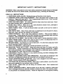
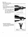
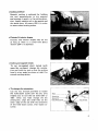
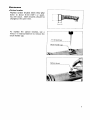
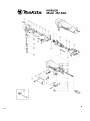
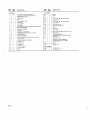
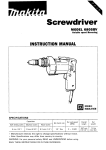
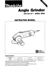
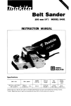
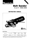
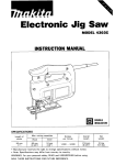
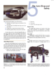
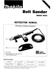
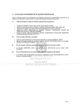
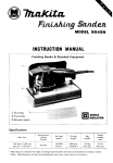
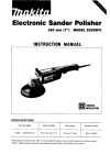
MODEL JN1600
INSTRUCTION MANUAL
DOUBLE
INSULATION
Max. cutting capacities
Min. cutting radius
Inside edge
Continuous
rating
(Input)
,,,Kite
7 mm
soow
2,200
-
Mild steel
1.6mm
(1116")
Stainless
Outside edge
1.2"
15"
(3164")
(5/8")
19/32'')
Strokes
Net
length
245"
Power
weight
1.5kg
(9-5/8") (3.3Ibs)
2m
(6.6 ft.)
* Manufacturer reserves the right t o change specifications o f parts and accessories without notice.
* Note: Specifications of parts and accessories may vary from country t o country.
IMPOR TANT SAFETY INSTR UCTIONS
WARNING: When using electric tools, basic safety precautions should always be followed
to reduce the risk of fire, electric shock, and personal injury, including the following:
READ ALL INSTRUCTIONS.
1. KEEP WORK AREA CLEAN. Cluttered areas and benches invite injuries.
2. CONSIDER WORK AREA ENVIRONMENT. Don't use power tools in damp or wet
locations. Keep work area well lit. Don't expose power tools to rain. Don't use tool
in presence of flammable liquids or gases.
3. KEEP CHILDREN AWAY. All visitors should be kept away from work area. Don't
let visitors contact tool or extension cord.
4. STORE IDLE TOOLS. When not in use, tools should be stored in dry, and high or
locked-up place - out of reach of children.
5. DON'T FORCE TOOL. It will do the job better and safer a t the rate for which it
was intended.
6. USE RIGHT TOOL. Don't force small tool or attachment to do the job of a heavyduty tool. Don't use tool for purpose not intended.
7. DRESS PROPERLY. Don't wear loose clothing or jewelry. They can be caught in
moving parts. Rubber gloves and non-skid footwear are recommended when working
outdoors. Wear protective hair covering to contain long hair.
8. USE SAFETY GLASSES. Also use face or dust mask if cutting operation is dusty.
9. DON'T ABUSE CORD. Never carry tool by cord or yank it to disconnect from receptacle. Keep cord from heat, oil, and sharp edges.
10. SECURE WORK. Use clamps or a vise to hold work. It's safer than using your hand
and it frees both hands to operate tool.
11. DON'T OVERREACH. Keep proper footing and balance at all times.
12. MAINTAIN TOOLS WITH CARE. Keep tools sharp and clean for better and safer
performance. Follow instructions for lubricating and charging accessories. Inspect
tool cords periodically and if damaged, have repaired by authorized service facility.
Keep handles dry, clean, and free from oil and grease.
13. DISCONNECT TOOLS. When not in use, before servicing, and when changing accessories, such as blades, bits, cutters.
14. REMOVE ADJUSTING KEYS AND WRENCHES. Form habit of checking to see
that keys and adjusting wrenches are removed from tool before turning it on.
15. AVOID UNINTENTIONAL STARTING. Don't carry plugged-in tool with finger on
switch. Be sure switch i s OFF when plugging in.
16. OUTDOOR USE EXTENTION CORDS. When tool is used outdoors, use only extension cords intended for use outdoors and so marked.
17. STAY ALERT. Watch what you are doing, use common sense. Don't operate tool
when you are tired.
18. CHECK DAMAGED PARTS. Before further use of the tool, a guard or other part
that i s damaged should be carefully checked to determine that it will operate properly and perform i t s intended function. Check for alignment of moving parts, binding
2
of moving parts, breakage of parts, mounting, and other conditions that may affect
i t s operation. A guard or other part that is damaged should be properly repaired or
replaced by an authorized service center unless otherwise indicated elsewhere in this
instruction manual. Have defective switches replaced by authorized service center.
Don't use tool if switch does not turn it on and off.
19. GUARD AGAINST ELECTRIC SHOCK. Prevent body contact with grounded surfaces. For example; pipes, radiators, ranges, refrigerator enclosures.
20. REPLACEMENT PARTS. When servicing, use only identical replacement parts.
SAVE THESE INSTRUCTIONS.
VOLTAGE WARNING: Before connecting the t o o l t o a power source (receptacle, outlet, etc.) be sure
the voltage supplied is the same as that specified o n the nameplate o f the tool. A power source with
voltage greater than that specified f o r the t o o l can result in SERIOUS INJURY t o the user - as well as
damage t o the tool. If in doubt, DO N O T PLUG IN THE TOOL. Using a power source with voltage
less than the nameplate rating i s harmful t o the motor.
Nibbler & Standard Equipment
Tool body
Punch
3
How t o use
0
Before cutting with the nibbler
Coat the cutting line with machine oil when cutting mild steel or stainless; use light oil
when cutting aluminum.
.Switch operation
First, turn the safety lock to the FREE
position. Then squeeze the switch lever
(paddleswitch) to put on the tool; release
it to put it off.
Note: The switch lever (paddle switch)
does not work with the safety
lock in the LOCK position.
Do not try to work the switch
lever (paddle switch) with the
safety lock on. Not using the tool,
put on the safety lock.
L
Switch lever (Paddle switch)
I
F L O C K condition)
0
Permissible cutting thickness
The groove in the end of the die serv s as
the gauge for allowable cutting thickness.
Do not attempt to cut any plate that will
not fit into this groove.
mild steel:
1.6 mm (1116")
4
I I
Statinless:
1.2 mm (3/64")
0
Cutting method
Smooth cutting is achieved by holding
the tool perpendicular to the material
and moving it gently in the cutting direction. Apply machine oil to the punch and
die about every 10 meters (33ft) in order
to assure clean cutting action.
.Cutting corrugated metals
To cut corrugated sheet metals (with
wave-like surfaces), change die orientation and hold the tool so that the cutting
head is a t an angle (as shown a t right) for
smooth cutting action.
.To change die orientation
Use the hex wrench provided to loosen
the hold-down screw over the die. This
enables you to turn the die either 90" or
180". Once you have change the die
orientation, align the small hole on the
outer edge of the die with the centerline
of the hold-down screw, then fasten securely.
0
Blade replacement
To replace the blade, use the hex wrench
provided to loosen the hold-down screw
and remove the die. Then, use the wrench
to turn the screw to the left and remove.
Next, lift off the punch.
To install the blade, secure the screw and
hold-down screw carefully.
@
Revolving
I
hold-down screw
@ Punch
0 Screw
Hold-down screw
I
I
UJ
U4’
‘4
@ Die
*Following each use of the tool, clean off the cutter head, and lubricate with machine
oil, while revolving the head a few times. Not using the tool, put on the safety lock.
6
Maintenance
0
Carbon brushes
Replace carbon brushes when they wear
down to about 3 mm (1/8") or sparking will occur. Both brushes should be
changed at the same time.
To replace the carbon brushes, use a
minus (-1 head screwdriver to remove the
brush holder cap.
( - ) Screwdrlver
I
Brush holder cap
/ I
7
OPTIONAL ACCESSORlES
CAUTION:
The use of any other accessories not specified
in this manual might be hazaroous.
Die
Punch
Part No. 725004-8
Part No. 725005-6
8
NIBBLER
Model JNI 600
9
E NE
MA(
NE
1
4
P H. Screw M4x35 (With Warherl
25
1
Punch
2
1
Gear Housing [With Plane Bearing 6 &
Needle Bearing 8101
26
1
Screw
27
1
DlW
2
P H Screw M4x30 [With Warherl
1
Switch Cover
3
1
F Washer 8
4
1
Rod
28
29
5
1
Needle Bearing 1412
30
2
P H Screw M4x18 (With Waherl
6
7
1
Crank Shaft
31
1
Strain Relief
1
Spur Gear 4 4
32
2
Brush Holder Cap
8
9
1
F. Washer 8
33
2
Carbon Brush CB-53
1
Gear Housing Cover [With Needle Bearing 810 &
Needle Bearing 6091
34
1
Switch
10
1
Ball Bearing 608LB
35
2
Rivet 0 - 5
11
1
36
1
Name Plate
ARMATURE ASSEMBLY
(A~rembledltemr10,11.12.13&141
37
1
Motor Housing (With Brush Holder x 21
38
1
Cord Guard
40
1
CORD ASSEMBLY
[Assembled Cord. Plug & Cord Guard1
41
1
Leaf Spring
42
1
Stop Ring E-3
12
1
Fan 58
13
1
lnwlat8on Warher
14
Ball Bearing 627LB
15
1
1
16
1
Rubber Pin 4
17
2
H. Bolt M4x55 (With Washer)
18
1
Rubber Pin 4
43
1
Switch Lever
44
1
P," 4
45
1
Safety Lock
F I E L D ASSEMBLY lWlth Garter Sprlng X 21
19
1
Gear 23-37
20
1
21
1
T. Washer 6
Woodruff Key 3
22
1
S Screw M6x10
23
1
Pin 6
24
-
Ram
1
SWITCH LEVER ASSEMBLY
l A w m b l e d ltemi41.43 &451
ACCESSORIES
400
401
I
1
1
1
Wrench Holder 3-7
H.Wrench 3
MAKITA LIMITED ONE YEAR WARRANTY
Warranty Policy
Every Makita tool is thoroughly inspected and tested before leaving the factory. It is warranted to
be free of defects from workmanship and materials for the period of ONE YEAR from the date of
original purchase. Should any trouble develop during this one-year period, return the COMPLETE
tool, freight prepaid, t o one of Makita’s Factory or Authorized Service Centers. If inspection shows
the trouble is caused by defective workmanship or material, Makita will repair (or at our option,
replace) without charge.
This Warranty does not apply where:
repairs have been made or attempted by others:
there is evidence of normal wear and tear;
The tool has been abused, misused or improperly maintained ;
alterations have been made t o the tool.
I N NO EVENT SHALL MAKITA BE LIABLE FOR ANY INDIRECT, INCIDENTAL OR CONSEQUENTIAL DAMAGES FROM THE SALE OR U S t O F THE PRODUCT. THIS DISCLAIMER
APPLIES BOTH DURING AND AFTER THE TERM O F THIS WARRANTY.
MAKITA DISCLAIMS LIABILITY FOR ANY IMPLIED WARRANTIES, INCLUDING IMPLIED
WARRANTIES O F “MERCHANTABILITY” AND “FITNESS FOR A SPECIFIC PURPOSE,”
AFTER THE ONE-YEAR TERM O F THIS WARRANTY.
This Warranty gives you specific legal rights, and you may also have other rights which vary from
state t o state. Some states do not allow the exclusion or limitation of incidental or consequential
damages, so the above limitation or exclusion may not apply t o you. Some states do not allow
limitation o n how long an implied warranty lasts, so the above limitation may not apply t o you.
FIArtkirM”L,ud.
11-8.3-chome,
Sumiyoshi-cho. Anjo, Aichi 446, Japan
883246-063 B
PRINTED IN JAPAN
1983- 12-N