1
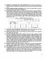
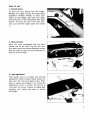
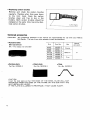
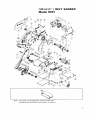
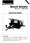
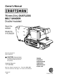
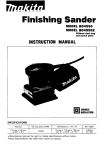
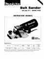
Belt Sander
I00 mm (4")
MODEL 9401
INSTRUCTION MANUAL
Specifications
Belt size
100mmx610mm
(4") x (24")
Belt speed
I
1
I
AMPS
(115V)
350m
(1,150ft.) lmin'
I
Overall
length
1
I
3 7 4 mm
(14-3/4")
1
1 ':E?,,
Power
w!egtht
7.3 kg
(16.1 Ibs)
1
(12Jft.)
Manufacturer reserves the right t o change specifications of parts and accessories without notice
Note: Specifications of parts and accessories may differ from country t o country.
IMPORTANT
SAFETY INSTRUCTIONS
(For All Tools)
WARNING: WHEN USING ELECTRIC TOOLS, BASIC SAFETY
PRECAUTIONS SHOULD ALWAYS BE FOLLOWED TO REDUCE
THE RISK OF FIRE, ELECTRIC SHOCK, AND PERSONAL
INJURY, INCLUDING THE FOLLOWING:
READ ALL INSTRUCTIONS.
1. KEEP WORK AREA CLEAN. Cluttered areas and benches invite injuries.
2. CONSIDER WORK AREA ENVIRONMENT. Don't use power tools in damp
or wet locations. Keep work area well lit. Don't expose power tools t o rain.
Don't use tool in presence of flammable liquids or gases.
3. KEEP CHILDREN AWAY. All visitors should be kept away from work area.
Don't let visitors contact tool or extension cord.
4.STORE IDLE TOOLS. When not in use, tools should be stored in dry, and high
or locked-up place - out of reach of children.
5. DON'T FORCE TOOL. It will do the job better and safer at the rate for which
it was intended.
6. USE RIGHT TOOL. Don't force small tool or attachment to do the job of a
heavy-duty tool. Don't use tool for purpose not intended.
7.DRESS PROPERLY. Don't wear loose clothing or jewelry. They can be caught
in moving parts. Rubber gloves and non-skid footwear are recommended
when working outdoors. Wear protective hair covering t o contain long hair.
8. USE SAFETY GLASSES. Also use face or dust mask if cutting operation is
dusty.
9. DON'T ABUSE CORD. Never carry tool by cord or yank it t o disconnect from
receptacle. Keep cord from heat, oil, and sharp edges.
IO. SECURE WORK. Use clamps or a vise to hold work. It's safer than using
your hand and it frees both hands t o operate tool.
1 1 . DON'T OVERREACH. Keep proper footing and balance at all times.
12. MAINTAIN TOOLS WITH CARE. Keep tools sharp and clean for better and
safer performance. Follow instructions for lubricating and changing accessories. Inspect tool cords periodically and if damaged, have repaired by authorized service facility. Inspect extension cords periodically and replace if
damaged. Keep handles dry, clean, and free from oil and grease.
13. DISCONNECT TOOLS. When not in use, before servicing, and when changing accessories, such as blades, bits, cutters.
2
14. REMOVE ADJUSTING KEYS AND WRENCHES. Form habit of checking to
see that keys and adjusting wrenches are removed from tool before turning
it on.
15. AVOID UNINTENTIONAL STARTING. Don't carry tool with finger on switch.
Be sure switch is OFF when plugging in.
16. EXTENSION CORDS. Make sure your extension cord is in good condition.
When using an extension cord, be sure t o use one heavy enough t o carry
the current your product will draw. An undersized cord will cause a drop
in line voltage resulting in loss of power and overheating. Table 1 shows the
correct .size t o use depending on cord length and nameplate ampere rating.
If in doubt, use the next heavier gage. The smaller the gage number, the
heavier the cord.
TABLE 1 MINIMUM GAGE FOR CORD SETS
0 - 25
26 - 50
Ampere Rating
More
Not More
Than
Than
0
6
10
12
-
6
10
12
16
51 - 100
101 - 150
A W G
18
18
16
14
16
16
16
12
;:
14
1
14
12
12
Not Recommended
17. OUTDOOR USE EXTENSION CORDS. When tool is used outdoors, use only
extension cords intended for use outdoors and so marked.
18. STAY ALERT. Watch what you are doing, use common sense. Don't operate
tool when you are tired.
19. CHECK DAMAGED PARTS. Before further use of the tool, a guard or other
part that is damaged should be carefully checked to determine that it will
operate properly and perform its intended function. Check for alignment of
moving parts, binding of moving parts, breakage of parts, mounting, and
any other conditions that may affect its operation. A guard or other part
that is damaged should be properly repaired or replaced by an authorized
service center unless otherwise indicated elsewhere in this instruction
manual. Have defective switches replaced by authorized service center. Don't
use tool if switch does not turn it on and off.
20. GUARD AGAINST ELECTRIC SHOCK. Prevent body contact with grounded
surfaces. For example; pipes, radiators, ranges, refrigerator enclosures.
21. REPLACEMENT PARTS. When servicing, use only identical replacement parts.
22. POLARIZED PLUGS. To reduce the risk of electric shock, this equipment has
a polarized plug (one blade is wider than the other). This plug will fit in a
polarized outlet only one way. If the plug does not fit fully in the outlet,
reverse the plug. If it still does not fit, contact a qualified electrician to install
the proper outlet. Do not change the plug in any way.
3
VOLTAGE WARNING: Before connecting the tool t o a power source (receptacle,
outlet, etc.) be sure the voltage supplied is the same as that specified on the
nameplate of the tool. A power source with voltage greater than that specified
for the tool can result in SERIOUS INJURY t o the user - as well as damage t o
the tool. If in doubt, DO NOT PLUG IN THE TOOL. Using a power source with
voltage less than the nameplate rating is harmful to the motor.
SAVE THESE INSTRUCTIONS.
4
How
to use
1. Switch action
To start the tool, simply pull the trigger.
Release the trigger t o stop. For continuous
operation without having t o keep your
finger on the trigger, just pull the trigger
and then push in the lock button with your
thumb. To stop the tool from lock position, just pull the trigger again and release
it.
2. Mounting belt
With the tool unplugged and the lever
pulled out all the way, slip the belt over
the rollers with the arrow direction on the
belt the same as that of tool revolution (or
belt life i s shortened).
3. Belt adjustment
Flip sander over on i t s back and use the
adjustment knob to obtain equal tension of
belt over the front and back rollers. Then
plug in sander and switch it on, using the
adjustment knob to center the belt as it
runs over the rollers. Failure t o adjust belt
properly over rollers can result in frayed
belt edges.
5
0
Replacing carbon brushes
Remove and check the carbon brushes
regularly. Replace when they wear down
t o the limit mark. Keep the carbon
brushes clean and free to slip in the
holders. Both carbon brushes should be
replaced a t the same time. Use only identical carbon brushes.
/
Limit mark
Optional accessories
CAUTION:
The accessories specified in this manual are recommended for use with your Makita
Belt Sander. The use of any other accessory might be hazardous.
Abrasive belts
0
Grit
Belt type and use
AA
I
Part No.
I
Use
I ,”,:”,”,’,”,
- For wood. iron and steel
Coarse
742322-9
Medium
0
Carbon plate
Part No. 423029-3
*Steel plate
Part No. 342328-3
0
Step
Part No. 342332-2
CAUTION :
Install the steel plate so that THE EDGE OF THE STEEL PLATE W I L L NOT
PROTRUDE FROM THE EDGE OF THE FRAME ON THE SIDE WITH THE
BELT INSTALLING LEVER.
I F THE PLATE I S ALLOWED TO PROTRUDE. I T MAY CAUSE INJURY.
6
5
lOOmm(4") BELT SANDER
Model 9401
Note: The switch, noise suppressor, plug and other part
configurations may differ from country to country.
7
MACHINE
MACHINE
1
1
Dust Collector Bracket
Knob 55
4
P. H. Screw M5xlB [With Washer)
39
40
1
2
1
Retaining Ring S-12
Tension Roller Arm
3
1
Fan 74
41
1
4
1
P. H . Screw M5x12 [With Washer)
42
1
Cup Washer 12
5
1
separator
43
1
6
7
1
2
Dust Collector Cower
P. H. Screw M5x25 (With Washer1
Tension Roller
(With Plane Bearing 12 & Swngs S h w t l
44
1
CupWasher 12
8
2
P. H. Screw M5x28 (With Werharl
45
1
Tension Roller Shaft
9
1
Ball Bearing 6200LLB
46
3
P. H. Screw M5x18 [With Washer)
10
11
1
47
1
B.H cover
48
1
Driving Roller
49
50
1
Balance Plate
1
CupWaiher 12
12
2
Fan 90
ARMATURE ASSEMBLY
IAsambled ltems9, 10. 11, 13& 141
H. Bolt M5x45 [With Warharl
13
1
1
Insulation Washer
51
1
Ball Bearing 6 2 W L L B
52
4
P. H. Screw M4xlO [With Washed
15
16
17
1
Rubbor Pin 4
6
3
1
1
Baffle Plats
FIELD ASSEMBLY
(With Garter Spring x 21
5
4
55
1
1
Strap Washer
Sled Plate
5
6
2
Cork Rubbar Plats
Leaf Spring
18
2
1
Rivet 0-5
57
5 8
1
Torsion Spring 18
1
Edgs Slider
20
21
2
Brush Holder Cap
59
6
2
Carbon Brush
60
1
C. H. k r e w M5x18
SupOort Pin
22
1
Motor Housing
[With Brush Holder x 2 & S.Screw M5x8 x 21
61
1
Needle Bearing E10
23
1
V-Pulley 6-24L
62
1
Heliul Gear 10
24
1
Dust Bag
63
1
Ball Bearing 62WLLB
25
5
1
1
Gear Cover
5
P. H. Screw M5xl8 [With Washer)
1
V-Pulley 6-55.7
1
Poly V-Balt 6-355
1
14
1
19
Name Plate
~
6
P. H. Screw M4x30 lWlth Warharl
4
Key 4
R u w r Pin 4
1
CORD ASSEMBLY
(Assembled Cord. Plug & Cord Guard1
65
6 6
27
1
Cord Guard
67
28
1
Strain Relief
6
29
2
P. H. Screw M4x18 lWith Warharl
69
1
30
1
Slwvt, 6
70
A.R.
31
1
P. H. Screw M5x16 [With Washed
71
1
32
1
Switch
72
1
Belt cow,
34
1
Screw MBx72
73
1
P. H. Screw M5x40 [With Washer)
2
6
2 I; 1
I;I
37
38
F.Washer 8
Comprsuion Spring 9
HandleCover
1
8
Helical Gear 42
T. Washer 12
Retaining Ring S-12
ACCESSORIES
4W
I
1
I
Abrasive Bell
Frame (With Plane Bearing 12 & Swonge Sheet1
Note: The Switch, noise suppreuor. plug and other part IPsCifiCatiOns may differ from country to Muntrv.
8
MAKlTA LIMITED ONE YEAR WARRANTY
Warranty Policy
Every Makita tool is thoroughly inspected and tested before leaving the factory. It is warranted to
be free of defects from workmanship and materials for the period of ONE YEAR from the date of
original purchase. Should any trouble develop during this one-year period, return the COMPLETE
tool, freight prepaid, to one of Makita’s Factory or Authorized Service Centers. If inspection shows
the trouble is caused by defective workmanship or material, Makita will repair (or at our option,
replace) without charge.
This Warranty does not apply where:
repairs have been made or attempted by others:
repairs are required because of normal wear and tear:
The tool has been abused, misused or improperly maintained;
alterations have been made to the tool.
IN NO EVENT SHALL MAKITA BE LIABLE FOR ANY INDIRECT, INCIDENTAL OR CONSEQUENTIAL DAMAGES FROM THE SALE OR USE OF THE PRODUCT. THIS DISCLAIMER
APPLIES BOTH DURING AND AFTER THE TERM OF THIS WARRANTY.
MAKITA DISCLAIMS LIABILITY FOR ANY IMPLIED WARRANTIES, INCLUDING IMPLIED
WARRANTIES OF “MERCHANTABILITY” AND “FITNESS FOR A SPECIFIC PURPOSE,”
AFTER THE ONE-YEAR TERM OF THIS WARRANTY.
This Warranty gives you specific legal rights, and you may also have other rights which vary from
state to state. Some states do not allow the exclusion or limitation of incidental or consequential
damages, so the above limitation or exclusion may not apply to you. Some states do not allow
limitation on how long an implied warranty lasts, so the above limitation may not apply to you.
Makita Corporation
3-11-8, Sumiyoshi-cho,
Anjo, Aichi 446 Japan
8830800061
PRINTED IN JAPAN
1992 - 8 - N