1
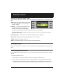
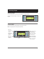
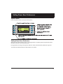
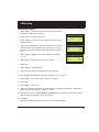
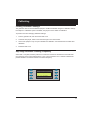
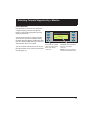
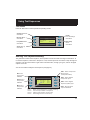
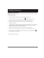
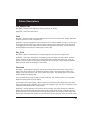
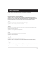
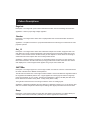
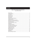
700A Series
Portable Video
Test Generators
Quick Start Guide
Contents
Model 700A, 701A Video Test Generators
Quick Start Guide
Getting Started.....................................................................................................................................................3
Computer Interfaces...........................................................................................................................................4
User Interface.........................................................................................................................................................5
Selecting Formats................................................................................................................................................6
Selecting Images..................................................................................................................................................7
Gating Outputs.....................................................................................................................................................7
Setting Power Save Preferences ....................................................................................................................8
Calibrating Generator.........................................................................................................................................9
Adjusting Horizontal Scan Frequency....................................................................................................... 11
Detecting Formats Supported by a Monitor........................................................................................... 12
Using Test Sequences...................................................................................................................................... 13
Testing Audio...................................................................................................................................................... 15
Testing HDCP Interfaces................................................................................................................................. 15
Generating Psuedo Random Noise............................................................................................................. 16
Using Video Generator Manager................................................................................................................. 17
Creating Video Formats................................................................................................................................... 18
Modifying Test Sequence............................................................................................................................... 19
Pattern Descriptions......................................................................................................................................... 20
Updating Firmware........................................................................................................................................... 24
Specifications...................................................................................................................................................... 25
Service and Support Contacts . ................................................................................................................... 26
2
Getting Started
Using AC Power
Use only the AC adaptor provided with the generator to avoid operator injury and damage to the generator.
Using Battery Power
The generator uses six AA rechargeable nickel metal hydride (NiMH) batteries, which can be recharged
about 1000 times.
You may use alkaline batteries instead, but not while the AC charger is connected to the generator. Only
NiMH batteries can be safely recharged in the generator.
All batteries in the generator must be the same type.
The supplied batteries may not come fully charged. Use the supplied AC charger to charge the batteries
for at least 18 hours. The AC adaptor may be used to operate the generator and to recharge the batteries at the same time.
With fully charged batteries, the generator should operate for about 8 hours using VESA mode. Using
the LCD backlight, DVI, NTSC/PAL, or RF features will reduce the battery life. The generator displays a
low battery message when the NiMH batteries need recharging, or when the alkaline batteries need to
be replaced.
3
Computer Interfaces
SDI/HD-SDI
(Active on 701A only)
DVI interface on 700A
outputs analog signals
only, using included
DVI-to-VGA adaptor.
�����������������������
���
�
�
�
�
�
�
�
�
������
�������������
������������
�������������
�������
������
�������������
�������
������
����������������
���������
�����������
���������
����������
������������
�������������������
����������������������
�����������
�������������
���������
����������
������������������������������������������������������
����������������������������������������������������
����������������������������������
����������������������������������������������������
4
User Interface
LCD Display
The LCD window displays messages and menu options.
�������������������������
����������
������
������
������
��������������������
�������������������
�������������������
�������������������
������
������
������
������
������
���������������������������������
��������������������������������
���������������������������
����������������������������
Function Buttons
������
����������������
����������������
������
�����
�����������������������
������������������������
���������������������
�����������������
������������
����
�����������������
��������������
������
��������������
����������������
������������������
�����
������
������
�����
����
������
������
���������������������
��������������������
����������
���������
�����������������������
��������������������
������������������������
����������������������������
�������������������������
������
���������
������
����
�����������
��������������
����������������
���������������
������
�������
�����
�������
�������
�������
�����������
�������������
��������
������������
������������
���������
������������
���������
�������������
���������������������
�����������������������
�����������
5
Selecting Formats
Viewing Formats by Signal Type
Press the Signal Type button, and then select a signal type, to list formats based on the selected signal
type.
VESA Red, green, blue component color video
per VESA standards. (DVI-to-VGA adaptor
used for outputs.)
HD/SDI
NTSC/PAL Composite color baseband video
signal (BNC connector) and Separate Luminance and Chrominance video signals
(S-Video connector) or RGB component video per NTSC and PAL standards.
Names of formats using modulated RF output end with _Cnn, where nn is the NTSC-M or PAL-G
television channel used.
HDTV/SDTV-RGB Luminance plus color difference signals per HDTV standards
HDTV RGB RGB component color video signals per HDTV standards
HD/SDI Digital video signals (701A only)
USER User-defined formats, of any type, stored in non-volatile memory
Selecting Formats
Press the Format button to select from a list of video formats of the type selected from the Signal Type
menu.
Reloading Standard Formats
If you modify or delete standard formats, you can restore the original formats by reloading the standard
formats.
To reload the standard formats:
1. Select Options > Clr_Fmts to delete all formats, including user-created formats.
2. Select Options > Reload Fmts to restore the standard formats to their original memory locations.
The standard formats will replace any user-created formats in the original memory locations. Usercreated formats in locations not previously occupied by a standard formats will not be replaced.
6
Selecting Images
Selecting Images
Press the Image button to select from list of available test images (patterns).
You cannot modify the images, or add your own
images.
������������������������
�������������������������
�������������������������
������������������������
Gating Outputs
Press the Gating button to gate outputs, and to switch sync types.
Note: Color gating works for all images except Ramp.
���������
���������
������
�����������
���������
������
����������
���������
������
�������������������������
�������������������������
�������������������������
��������������������������
�������
������
�������
�����
�������������������
��������������
�����������������
��������������������
��������������
��������������������
�������������������
���������������������
��������������
7
Setting Power Save Preferences
Options Menu
Press the Options button to set system-level options.
Hot Plug:In
Setting Power Save Preference
When the Power Save preference is on, and the generator is on battery power, the generator will turn
off after 30 minutes of no front panel activity.
If the generator is running a test sequence in Burn-in mode, the Power Save preference is ignored.
To set the Power Save preference, select Options > Pwr Save.
8
Calibrating
Model 700A and 701A generators use programmable hardware to set the amplitude calibration factors
for analog video outputs. These calibration factors are stored in Flash EPROM, and are not lost if the
batteries are run down or removed.
Quantum Data calibrates the analog video and sync output amplitudes in new generators to published
specifications. You can recalibrate these amplitudes over a nominal range to meet your specific testing
conditions.
WARNING: Recalling the original factory calibration settings is not possible after saving
your own settings.
Equipment Needed for Calibration
•
DC voltmeter capable of measuring from 0 to 1 volt with a minimum resolution of 2 millivolts
•
Precision 75 ohm (+/- 1%) input terminator for the voltmeter
•
Test cable to connect the voltmeter to the R, G, B and ground pins on the VGA connector
•
Oscilloscope with a precision 75 ohm (+/- 1%) input impedance and suitable gain and bandwidth to
display a 1.00 Volt pk-pk signal with 3.579 MHz color carrier
•
75 ohm coaxial cable to connect the oscilloscope to the BNC TV output
•
Vector scope
9
Calibrating
Calibrating Outputs
1. Select Options > Calibrate > Reset to set the generator’s calibration factors to default nominal values.
2. Press Options > Calibrate > Full Scale.
3. Set the voltmeter’s scale factor to be able to measure a nominal
1000 millivolts DC.
4. Using a VGA-to-BNC cable, connect the generator’s red output to
the positive input on the voltmeter, with a 75 ohm (+/‑ 1%) input
terminator. Connect the negative lead of the meter to any ground
pin.
5. Select R_FS+ or -R_FS to set the DC output level to 1000 mV
+/‑ 3 mV.
6. Repeat steps 4 and 5 for the green and blue outputs.
�����������������
�
������������������������
������
������������������������
������������������������
������������������������
������������������������
������������������������
������������������������
������������������������
������������������������
7. Select Save.
8. Select Options > Calibrate > Zero.
9. Connect the red output to the positive input of the voltmeter.
10. Select R_Zero+ or -R_Zero to set the DC output level to 0 mV +/‑ 3 mV.
11. Repeat steps 9 and 10 for the green and blue components.
12. Select Save.
13. Select Options > NTSC_CAL.
14. Adjust the oscilloscope’s timebase and sweep trigger to view the entire waveform. Adjust the G_
NTSC so that its chrominance is 100 IRE or 714mV.
15. Using a vector scope, use the R_NTSC and B_NTSC options to adjust the red and green outputs
using so that their signals align with the 2% boxes.
16. Press Save.
Note: The modulated RF output does not have any calibration settings.
10
Calibrating
Locking Calibration Settings
The generator uses an internal hardware jumper to enable and disable changes to calibration settings.
If the Options > Calibration option is available, the jumper is set to enable re-calibration.
To prevent users from changing calibration settings:
1. Turn the generator off, and remove the back cover.
2. Locate the J10 jumper, which is near the lower-right corner of the board.
3. Connect the jumper to only one pin to disable user calibration. Connect both bins to enable user
calibration.
4. Install the back cover.
Adjusting Horizontal Scanning Frequency
Select Test > Freq Shift, and then press the +/- buttons to increase or decrease the horizontal scanning frequency of the current video format +/- 10% in 2% increments. The ^ character indicates the
percent deviation. The bottom number is the actual frequency.
� � � � � � � � � � �� � � � �
��������������������
�����������
� � � � �� � � � � � � � � � �
11
Detecting Formats Supported by a Monitor
Learn Monitor
If the generator is connected to a VESA DCCcompliant display, press the Learn Monitor
button to view formats supported by both the
display and generator.
To view the format names, select the Details
option after the generator completes reading
the EDID (Extended Display Identification Data)
data. The display’s EDID data may include nonVESA formats, which are not listed.
You cannot select formats from this list, but the
DDC Step feature can be used to test the listed
formats (page 14).
��������������
�����������������
���������������
�������
��������������������
���������������������
�����������������
����������
�����������������������
������������������
����������
��������������������������
�������������������������
12
Using Test Sequences
Test Menu
Press the Test button to select special test operating modes.
�������������
��������
������������
��������
������������������������
�������������������������
�����������
�������������������������
���������������
��������
�����
�������������
��������
��������
����
��������
������������
��������
Running Test Sequence Manually
The generator includes a test sequence, which specifies a series of format and image combinations. To
run the test sequence, select Test > Sequence > Run, and then press the +/- buttons to step through the
sequence. Use the menu buttons to gate video color information, change sync types, and turn all signal
outputs on and off.
You can use VGM to modify the test sequence (see page 19).
����������������������
�����������
�����������������
���������
���������
������
�����������
���������
������
����������
���������
������
�������������������
�������������������
��������������������
��������������������
��������������������
��������������
��������������������
�������������������
���������������������
��������������
�������
�������
�������
�������
����������������������������������������
�������������������������������
���������������������������������
�������������������������������
13
Using Test Sequences
Running Test Sequence in Burn-In Mode
Select Test > Burn-In > Run to automatically cycle through the test sequence. When the Burn-In mode
is stopped, you can use the menu buttons to gate video color information, change sync types, and turn
all signal outputs on and off.
NOTE: The Burn-In mode disables the Power-Save feature, if enabled.
���������������������
��������������
������������������
��������
��������������������
��������������������
��������������������
��������������������
�������������������
���������
���������
������
�����������
����������������
����������
����������������
��������������������
�������������������
��������������������
��������������
�������
�������
�������
�������
���������������������������������������
����������������������������
���������������������������������
�������������������������������
������������
����������������
���������������
������
Creating Test Sequence for DDC Displays
If the generator is connected to a VESA DCC-compliant display, press the Learn Monitor, and then Test
> DDC Step to setup a test of each format supported by the display.
Press the + button to render the current image with each video format supported by the display.
Press the - button to render all images at the current format.
Select the Run option to automatically test all images for each video format.
When using automatic mode, select Stop to use manual mode.
14
Special Tests
Testing Audio
Select Test > Audio to independently toggle stereo audio output channels on and off.
On a 701A generator, the left channel is also the monophonic audio source for the modulated RF output.
Testing HDCP Interfaces
���������������
��������
������������������
�������������
�������������
�������������������
����������������
�������������
������������
�����������������
�����������
�����������������
Model 701A video test generators may be equipped with an optional production (private) key for testing
High-bandwidth Digital Content Protection (HDCP) interfaces of DVI receivers that support HDCP. For
more information about HDCP, see http://www.digital-cp.com/.
To output HDCP-encyrpted video content:
1. Connect the DVI connector of the generator with the DVI connector of the device under test.
2. Choose a DVI video format supported by the device.
3. Press Test > HDCP > Start to output HDCP encrypted content.
The display on the generator indicates if the test passed or failed. If the test passed, the currently
selected pattern is displayed on the device under test. Noise is displayed if the HDCP authentication failed.
After the initial authentication of the connection is established, the generator displays the number of
authentication verficiation cycles until you stop the test.
During the test, if you reconnect the cable or restart the device under test, the test should restart
automatically.
4. To stop the test, press the Exit soft key or any gray key.
15
Special Tests
Generating Pseudo Random Noise
When the generator is connected to a device that supports the Quantum Data pseudo random noise
standard, press Test > PR Noise to output the noise pattern as a static image. Depending on how the
device is designed, it may compare the pattern output by the generator with an identical pattern, created
internally, to detect errors in the cable and in the device itself.
16
Using Video Generator Manager
About VGM
Video Generator Manager (VGM) is a Windows-based application for creating and editing formats and
test sequences. As many as 132 formats and one test sequence can be stored in the generator.
VGM was originally created for use with Quantum Data 80x video generators. The 700A-Series generators support only some VGM features. For information about using VGM, see the VGM help file.
VGM Quick Tour
1. Connect the generator to your computer using a null modem serial cable.
Note: You may not be able to connect to the generator when it is Power Save mode.
2. Start VGM, and then select Generator > Connect.
3. In the Select Port dialog box, select the Serial option, and then click OK.
The name of the connected generator is listed in the bottom half of the VGM window.
4. Click the View Formats icon
to view the formats available in the generator, and then doubleclick the format you want the generator to use.
5. Click the
Image List icon to view the available images, and then double-click the image you
want the generator to use.
17
Creating Video Formats
Editing Video Formats
You can use VGM to create your own video formats. You can start with a default format in the VGM
format editor, or copy an existing format.
To create a video format:
1. Connect the generator with VGM, and then double-click the generator name.
2. Click the View Formats icon to list the available formats.
3. Right-click a format that is similar to the format you want to create, then select Copy to create a
copy of the format. The name of the new format can be based on the original format, followed by an
underscore and number. But you can use any name.
4. Right-click the copied format in the format list. Select Edit, and then click Yes to open the Format
Editor.
5. Specify the format parameters.
The format editor works as described in the VGM help file, except unlike our other models, the 70x
generators store formats by specific numeric locations, and not by name. The integer portion of
the field defining the horizontal size in millimeters specifies the storage location of the format in the
generator. The physical size entries have no affect on how test images are displayed on the 700A
series.
For example, if you want to save the new format in the location “empty35”, you would enter 35 to
the left of the decimal point in the field for the horizontal size in millimeters. If you do not change
this number, the edited format will replace the previous version of the format (the one you copied
to use as a basis for your custom format) when you upload it back to the generator. You will not get
any warnings that you are about to overwrite a memory location.
Note: If you do overwrite the format, you can recover the original default format by first clearing
formats and then reloading formats.
6. Select File > Save to save the format on your PC, and then close the Format Editor window.
7. In the VGM data pane, select the format, and click the Send Data icon
the generator.
to store the format on
8. Reload the formats.
18
Modifying Test Sequence
Editing the Test Sequence
The generator has a default sequence, which you can edit in VGM. One sequence can be stored in the
generator at the same time.
To modify the test sequence:
1. Connect the generator with VGM, and then double-click the generator name.
2. In the generator window, click the Sequence List icon
to display the sequence name.
3. Right-click the sequence name, and then select Edit to open the Sequence Editor.
4. Select the 700A generator from the Generator list. Do not select the virtual generator.
5. Modify the test sequence.
VGM help describes the basic operation of the Sequence editor. Specify only a format and image
for each step. Do not use the No Change value. The 700A-Series generators do not support the
output gating and sync options, and the No Change value.
6. Select Edit > Edit Sequence Name to save the sequence as a new sequence file.
7. Select File > Save to save the sequence on your PC, and then close the Sequence Editor.
8. In the top half of the main VGM window, select the sequence, then click the Send Data icon
store the sequence on the generator.
to
To run the test sequence, see page 13.
19
Pattern Descriptions
Flat_Wht/(R,G,B)
Description - Fills the screen with white, blue (B), green (G) or red (R).
Application - Use to test chrominence.
Grid
Decription - White crosshatch on a black background. The lines form square boxes. A single pixel dot is
located in the center of each crosshatch box.
Application - Use the Grid pattern to test convergence. To accurately produce an image on a color monitor, the three electron beams in the CRT must meet (converge) at the same location at the same time.
Lines displayed on a misconverged monitor appear as several multi-colored lines, and the transitions
between different colored areas contain fringes of other colors.
Rev_Grid
Description - Black crosshatch drawn on a white background. The lines form square boxes.
Application - Use to test convergence. To accurately produce an image on a color monitor, the three
electron beams in the CRT must meet (converge) at the same location at the same time. Lines displayed on a misconverged monitor appear as several multi-colored lines, and the transitions between
different colored areas contain fringes of other colors.
Overscan
Description - The image has three parts. The first part consists of five white circles. A large circle is
drawn in the center of the screen. Its diameter equals the lesser of the video height or width of the
display. A circle also is drawn in each of the corners of the screen. The diameter of the corner circles
equals one-fifth of the display width.
The second part of the image consists of a white crosshatch. The number of boxes in the crosshatch
depends on the physical size of the display.
The last part of the image consists of white tic marks on the horizontal and vertical center lines of the
image. The marks are one pixel thick. Every other mark is slightly longer. The color of the pattern can be
changed with the individual video output controls. Application - Used for detecting non-uniformity and non-linearity. The image presents an undistorted
display, the horizontal and vertical sweeps of the electron beam across the face of the CRT should be
at uniform speeds. Any non-uniformity in the sweep causes portions of an image to stretch while other
portions are compressed. Non-linearity in a monitor shows up in several ways. It may be present across
20
Pattern Descriptions
the entire screen, in a large portion of the screen, or localized in a very small area.
Raster
Description - Black display (nothing being displayed).
Application - Useful for centering the raster on a CRT. Many monitor applications require that the displayed image or text fit completely within a bezel that surrounds the CRT. This usually requires that you
first center the blank raster on the face of the CRT, and then center the image within the raster.
Cutoff
Description - The entire active video area is filled with a shade of gray.
Application - Useful for testing chrominence and contrast.
Window
Description - Single white box in the center of active video. The size of the box is one-third the width
and height of the active video area.
Application - Use for brightness control adjustment.
Focus
Description - This image fills the screen with white M characters.
Application - Used for testing focus.
ColorBar
Description - The image has 7 full-height vertical color bars.
Application - Useful for verifying that none of the video channels are bad or connected incorrectly.
GrayBar
Description - The image has 16 full-height vertical graybars. The intensity of the bars iincreases from left
to right. All bars are untined gray at all levels.
Application - Useful for testing brightness control adjustment and brightness uniformity tests.
21
Pattern Descriptions
Regulate
Description - The image has a pair of white outlined boxes which surround a blinking solid white box.
Application - Tests for proper high voltage regulation.
Checker
Description - The image’s active video area is equally divided into a 6x6 checkerboard of black and
white boxes.
Application - The pattern is based on a proposed ANSI method of measuring the contrast ratio of video
projection systems.
Dot_12
Description - The image’s active video area is filled with multiple rows of white, single pixel dots. The
dots define the corners of what would appear to be square boxes if all connecting pixels were lit. The
number of rows of boxes and the number of boxes per row depends on which version of the image is
selected and the screen aspect ratio of the currently-loaded format.
Application - Used to measure convergence. To accurately produce an image on a color monitor, the
three electron beams in the CRT must meet (converge) at the same location at the same time. Small
dots displayed on a misconverged monitor appear as a group of multi-colored dots.
SMPTEBar
Description - The image’s upper 67% of the image consists of a series of color bars. These bars match
the order of the bars in the SMPTE and EIA patterns.
The left side of the lower 25% of the image contains isolated -I and Q color difference signals that match
the original EIA and SMPTE patterns. The -I signal appears as a bluish-gray bar and the Q signal appears as a purple bar on a TV monitor. The bars are separated by a white (+100 IRE) bar. After the Q
blocks there are four blocks: black, (black - 4 IRE), black, (black + 4IRE).
The right side of the lower 25% of the image contains a narrow 12.5 IRE gray bar.
Application - Designed for adjusting the color settings of a television monitor by eye. It can also be used
with a TV waveform analyzer and vectorscope for testing video signal processors and color decoders.
Ramp
Description - This image provides an active video area starting from full black (+7.5 IRE for NTSC) at
one edge of the screen to full white (+100 IRE) at or near the opposite end of the screen.
22
Pattern Descriptions
Application - Useful for testing pixel anomolies and chrominance.
PulseBar
Description - The image looks like two vertical lines followed by a wide vertical bar on a display’s
screen. The first line is a red pulse. The pulse is 20 T for PAL and 12.5 T for NTSC formats. The second
narrower line is a 2 T white sine-squared pulse. T = 100 nSec for PAL and 125 nSec for NTSC formats.
The wide bar is white with sine-squared edges.
Application - This image is intended for TV formats, but can be displayed with any format up to 100
MHz.
Burst
Description - The left side starts with reference white and black levels. This is followed by six bursts
of square waves. Each burst is at a different frequency, forming vertical lines of various widths. The
frequencies, going from left to right, are 0.5, 1, 1.53, 2.04, 3.06 and 6.13MHz.
Application - The image can also be used with a TV waveform analyzer to check the frequency response of a video system. One scan line of the image, as it would appear on a waveform analyzer. High
frequency roll-off (loss) would show up as a decrease in the peak-to-peak swings on the right side of the
waveform. Low frequency roll-off would show up as a decrease in the peak-to-peak swings on the left
side of the waveform.
23
Updating Firmware
Updating Firmware
The generator’s operating system firmware is stored in Flash EPROM, which you can update via the serial port. Firmware updates are available from http://www.quantumdata.com/support/downloads/.
To install a firmware update:
1. Turn ON the generator and connect it to your PC using a null modem serial cable.
2. Start HyperTerminal with the proper communications setup (9600 bps, 8 data bits, no parity, 1 stop
bit, Xon/Xoff flow control). HyperTerminal Private Edition is recommended.
Note: You may not be able to connect to the generator when it is in Power Save mode.
If you are using a COM port other than COM1, choose File > Properties to select the desired COM
port.
3. Hit the return key to obtain an R> prompt.
Important Note: You must connect to the generator and obtain an R> prompt before you attempt the
download.
4. Turn OFF the generator .
5. Hold down the upper-left menu button and then press the On/Off button. The LCD screen will indicate that the generator is ready for the upload.
6. If necessary, expand the .zip archive file that contains the firmware update.
7. In HyperTerminal, select Transfer > Send Text File.
8. In the Send Text File dialog box, double-click the firmware filename to start the transfer.
The generator will display the progress of the update, which takes several minutes, and then restart
to complete the installation. If you need to cancel the installation, select Exit.
9. If the firmware update includes new or revised video formats, press Options > Clear Fmts, and
then select Yes to delete the current formats. Then press Options > Reload Fmts to load the new
formats.
24
Specifications
Video Formats
Storage:
132 total
Press Signal Type button to view signal types.
Edit method:
Windows-based VGM software
Test Images (Patterns)
Digital Video
Pixel rate:
Audio Outputs
Connecter:
3.5 mm stereo phone jack
Signals:
Left: 1 KHz tone
Right: 2 KHz tone
Press Image button to list images.
Horizontal Timing
Frequency:
1 KHz to 250 KHz
Total pixels:
144 to 4096
Active range: 16 to 4096 pixels
Vertical Timing
Frequency:
1 Hz to 650 Hz
Active lines:
1 to 4096
Scan types:
Progressive, 2:1 Interlace
Sync Types
Separate digital horizontal and vertical
Digital and analog composite
Bipolar HDTV
User Interface
Display:
4 x 20 character backlit LCD
Buttons:
9 function buttons, 8 menu buttons, 2
paging buttons
Computer Interface
Type:
RS-232, 9 pin D-sub
Protocol:
9600 baud, 8-N-1, Xon/Xoff
VESA EDID/DDC Support
Reads a monitor’s EDID data through DVI
connector, and shows list of supported
standard formats. DDC test mode for cycling
through supported standard formats.
Battery Power Operation
Video Outputs
Timing accuracy: 2%
Connectors:
Single link 75 MHz
See diagram on page 3.
Type:
Six AA 1500 mA-H rated rechargeable NiMH batteries (included)
Use time:
8 hours with fully charged NiMH
batteries. Less when using backlight,
DVI, NTSC, or RF features.
SDI / HD-SDI (701A only)
Connector: BN DI - SMPTE 292M-C
Links:
Single
Bit stream:
1.485 Gb/s and 1.485/1.001 Gb/s
Encoding:
4:2:2
Bits/component: 10-bits/component
Sampling mode: YCbCr
Signal swing: 800mV
Standards:
SDI - SMPTE 259M;
HD-SDI - SMPTE 292M-C
AC Power Operation
Type:
External charger/power supply supplied with unit
Input:
100-240 VAC @ 47-63 Hz
Output:
12V
Size and Weight
Size:
H 5.5 x W 8.25 x D 2 inches
H 140 x W 210 x D 51 mm
Ship weight:
4 lbs, including batteries
DVI
Connector:
DVI-1 dual link
Links:
Single link 25MHz-85MHz
Encoding:
RGB (4:4:4 with 8-bits/component)
TMDS differential swing:
150–1560 mVp-p (programmable)
25
Service and Support Contacts
To contact Technical Support, see http://www.quantumdata.com/contact/support.asp.
For factory-authorized service centers, see http://www.quantumdata.com/contact/locations.asp.
Model 700A, 701A Quick Start Guide
68-00198-D 01-Oct-2007
Copyright © 2007 by Quantum Data, Inc. All rights reserved.
The information contained in this document is provided for use by our customers and may not be incorporated into other products or publications without the expressed written consent of Quantum Data. Information furnished by Quantum Data is believed to be accurate and reliable.
However, no responsibility is assumed by Quantum Data for its use.
Quantum Data reserves the right to make changes at any time and without notice to its products to improve performance, reliability, manufacturing methods, and (or) marketability.
Documentation based on firmware version 1.0.0.
26