1
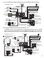
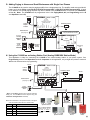
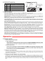
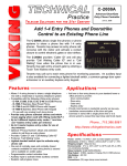
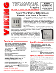
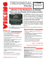
TECHNICAL
Practice
TELECOM SOLUTIONS
Practice
FOR THE
C-1000B
Door Entry and CCTV
Camera Controller
2 1 S T C E N T U RY
April 26, 2004
Add One or Two Doorboxes to an Existing
Phone Line and Provide CCTV Camera Control
The C-1000B allows single line phones or phone
systems to share a phone line with one or two
doorboxes or paging amplifiers. The C-1000B provides two Touch Tone controlled relays to operate
door strikes or gate openers and provides doorbox triggered CCTV camera switching.
Doorboxes and paging amplifiers can now be used
on single line, residential or home office applications as well as on fully loaded systems, because
they are no longer limited to installation on unused
trunk ports.
The C-1000B expands the potential installation sites for many peripherals such as doorboxes and paging amplifiers.
Features
• Allows two Viking doorboxes or paging amplifiers to
share a single telephone line with a residential or
business telephone system
• Doorbox triggered CCTV camera switching
• Custom ringing mode allows you to distinguish doorbox
calls from C.O. calls
• Compatible with the following Viking doorbox models:
W-1000, W-2000A, or W-3000
• Compatible with a single Viking handsfree phone
(E-10, E-20A, E-30, K-1700-3 or 1600A Series)
• Analog PABX/KSU station mode
• Call waiting tones indicate which doorbox is calling and
distinguish a doorbox call from a C.O. line call
Applications
• Add one or two Viking Doorboxes to your home or
office phones
• Switch between two CCTV cameras automatically
when either doorbox is activated
• Add paging amplifiers to provide loud ringing and
paging to businesses with single line phones or fully
loaded phone systems
• Provide commercial or residential security via two-way
handsfree communication from a door or gate
• Use as a line concentrator (one fax machine or
answering machine can answer three lines)
Phone...715.386.8861
h t t p : / / w w w. v i k i n g e l e c t r o n i c s . c o m
• Calls can be placed on hold when visitors call from the
doorbox or when paging
Specifications
• Provides two Touch Tone controlled N.O. or N.C. dry
contact closures (5 amp rating) for door strikes or gate
openers
Power: 120V AC/13.8V AC 1.25A, UL listed adapter provided
Dimensions: 133mm x 89mm x 44mm (5.25" x 3.5" x 1.75")
Shipping Weight: 0.9 kg (2 lb)
Environmental: 0° C to 32° C (32° F to 90° F) with 5% to 95%
non-condensing humidity
Door Strike Relay Contacts: 5A @ 30V DC/250V AC maximum
CCTV/Auxiliary Relay Contacts: .5A @ 125V AC, 1A @ 30V AC
Pulse Dialing Detection: 10 pps
Talk Battery: 30V DC
Maximum Doorbox Power Supply Length: 100 ft, 24 awg wire
Connections: (2) RJ11 jacks, (1) 12 position terminal block
• Keyless entry/postal lock input
• Built-in talk battery for “No C.O. Line” applications
• Auxiliary contact output for doorbells, cameras, etc.
[email protected]
IF YOU HAVE A PROBLEM WITH A VIKING PRODUCT, PLEASE CONTACT: VIKING TECHNICAL SUPPORT AT (715) 386-8666
Our Technical Support Department is available for assistance Monday 8am-4pm and Tuesday-Friday 8am - 5pm central time. So that we can give you better service, before you call please:
1. Know the model number, the serial number and what software version you have (see serial label).
2. Have your Technical Practice in front of you.
3. It is best if you are on site.
RETURNING PRODUCT FOR REPAIR
RETURNING PRODUCT FOR EXCHANGE
The following procedure is for equipment that needs repair:
1. Customer must contact Viking's Technical Support Department at 715-386-8666 to obtain a Return Authorization (RA)
number. The customer MUST have a complete description of the problem, with all pertinent information regarding the
defect, such as options set, conditions, symptoms, methods to duplicate problem, frequency of failure, etc.
2. Packing: Return equipment in original box or in proper packing so that damage will not occur while in transit. Static
sensitive equipment such as a circuit board should be in an anti-static bag, sandwiched between foam and individually boxed. All equipment should be wrapped to avoid packing material lodging in or sticking to the equipment. Include
ALL parts of the equipment. C.O.D. or freight collect shipments cannot be accepted. Ship cartons prepaid to:
Viking Electronics, 1531 Industrial Street, Hudson, WI 54016
3. Return shipping address: Be sure to include your return shipping address inside the box. We cannot ship to a PO Box.
4. RA number on carton: In large printing, write the R.A. number on the outside of each carton being returned.
The following procedure is for equipment that has failed out-of-box (within 10 days of purchase):
1. Customer must contact Viking’s Technical Support at 715-386-8666 to determine possible causes for the problem. The
customer MUST be able to step through recommended tests for diagnosis.
2. If the Technical Support Product Specialist determines that the equipment is defective based on the customer's input
and troubleshooting, a Return Authorization (R.A.) number will be issued. This number is valid for fourteen (14)
calendar days from the date of issue.
3. After obtaining the R.A. number, return the approved equipment to your distributor, referencing the R.A. number. Your
distributor will then replace the product over the counter at no charge. The distributor will then return the product to
Viking using the same R.A. number.
4. The distributor will NOT exchange this product without first obtaining the R.A. number from you. If you haven't
followed the steps listed in 1, 2 and 3, be aware that you will have to pay a restocking charge.
WARRANTY
Viking warrants its products to be free from defects in the workmanship or materials, under normal use and service, for a period of one year from the date of purchase from any authorized Viking distributor or 18 months from the date manufactured, which ever is greater. If at any time during the warranty period, the product is deemed defective or malfunctions, return the product to Viking Electronics, Inc., 1531 Industrial Street, Hudson, WI., 54016. Customer must contact Viking's
Technical Support Department at 715-386-8666 to obtain a Return Authorization (R.A.) number.
This warranty does not cover any damage to the product due to lightning, over voltage, under voltage, accident, misuse, abuse, negligence or any damage caused by use of the product by the purchaser or others.
Vikings sole responsibility shall be to repair or replace (at Viking's option) the material within the terms stated above. VIKING SHALL NOT BE LIABLE FOR ANY LOSS OR DAMAGE OF ANY KIND INCLUDING INCIDENTAL OR CONSEQUENTIAL DAMAGES RESULTING DIRECTLY OR INDIRECTLY FROM ANY BREACH OF ANY WARRANTY EXPRESSED OR IMPLIED, OR FOR ANY OTHER FAILURE OF THIS PRODUCT. Some states do not allow the exclusion or limitation of incidental or consequential damages, so this limitation may not apply to you.
THIS WARRANTY IS IN LIEU OF ALL OTHER WARRANTIES, EXPRESSED OR IMPLIED, INCLUDING THE WARRANTIES OF MERCHANTABILITY AND FITNESS FOR A PARTICULAR PURPOSE, WHICH ARE HEREBY EXCLUDED
BEYOND THE ONE YEAR DURATION OF THIS WARRANTY. Some states do not allow limitation on how long an implied warranty lasts, so the above limitation may not apply to you.
FCC REQUIREMENTS
This equipment complies with Part 68 of the FCC rules. Located on the equipment is a label that contains,
among other information, the FCC registration number and ringer equivalence number (REN). If requested, this
information must be provided to the telephone company.
The REN is used to determine the quantity of devices which may be connected to the telephone line.
Excessive REN's on the telephone line may result in the devices not ringing in response to an incoming call. In
most, but not all areas, the sum of the REN's should not exceed five (5.0) To be certain of the number of devices
that may be connected to the line, as determined by the total REN's, contact the telephone company to determine the maximum REN for the calling area.
This equipment cannot be used on the telephone company-provided coin service. Connection to Party Line
Service is subject to State Tariffs.
If this equipment causes harm to the telephone network, the telephone company will notify you in advance
that temporary discontinuance of service may be required. If advance notice isn't practical, the telephone company will notify the customer as soon as possible. Also, you will be advised of your right to file a complaint with
the FCC if you believe it is necessary.
The telephone company may make changes in its facilities, equipment, operations, or procedures that could
affect the operation of the equipment. If this happens, the telephone company will provide advance notice in
order for you to make the necessary modifications in order to maintain uninterrupted service.
If trouble is experienced with this equipment, please contact: Viking Electronics, Inc., 1531 Industrial
Street, Hudson, WI 54016 (715) 386-8666
If the trouble is causing harm to the telephone network, the telephone company may request you to remove
the equipment from the network until the problem is resolved.
The C-1000B uses the USOC jack RJ11C.
It is recommended that the customer install an AC surge arrester in the AC outlet to which this device is connected. This is to avoid damaging the equipment caused by local lightning strikes and other electrical surges.
This equipment is Hearing-Aid Compatible (HAC).
The telephone Consumer Protection Act of 1991 makes it unlawful for any person to use a computer or other
electronic device, including fax machines, to send any message unless such message clearly contains in a margin at the top or bottom of each transmitted page or on the first page of the transmission, the date and time it is
sent and an identification of the business or other entity, or other individual sending the message and the telephone number of the sending machine or such business, other entity, or individual. (The telephone number provided may not be a 900 number or any other number for which charges exceed local or long-distance transmission charges.)
PART 15 LIMITATIONS
This equipment has been tested and found to comply with the limits for a Class A digital device, pursuant to Part
15 of the FCC Rules. These limits are designed to provide reasonable protection against harmful interference
when the equipment is operated in a commercial environment. This equipment generates, uses, and can radiate radio frequency energy and, if not installed and used in accordance with the instruction manual, may cause
harmful interference to radio communications. Operation of this equipment in a residential area is likely to cause
harmful interference in which case the user will be required to correct the interference at his own expense.
Installation and Applications
VIKING ©
* Earth Ground
* Note: To increase surge protection, fasten a wire from
the screw terminal to Earth Ground (grounding rod, water
pipe, etc.)
C.O./Phone Line Input
Out to Telephones
Keyless Entry/Postal Lock
Contact Closure Input
(2)
Door Box 1 Line Input
3 4
5
PWR 13.8 VAC
COM
6
7
8
ON
PWR
D.S.1
TALK
OFF
OUT TO
PHONES
KEYLESS
C.C. INPUT
Door Strike 2 LED - Lights
while the door strike 2 relay
is activated.
9 10 11 12 13 14 15 16 17 18 19
N.O. N.C. - - - - AUX.
CONTACT
OUTPUT
SIG GND SIG GND SIG GND
VIDEO 1 IN VIDEO 2 IN VIDEO OUT
EARTH C.O. LINE
GND
INPUT
DOOR
STRIKE 2
Signal
Ground
2
DOOR
STRIKE 1
CCTV Video Output
1
DOORBOX 1
Signal
Ground
DOORBOX
PWR OUTPUT
CCTV Video 2 Input
KEYLESS CONTACT
CLOSURE INPUT
Signal
Ground
Power LED - Lights
while unit is powered.
Door Strike 1 LED - Lights
while the door strike 1 relay
is activated.
DOOR ENTRY / CCTV VIDEO
/ PAGING CONTROLLER
LINE OUT
TO PHONES
CCTV Video 1 Input
EARTH
GND
Power Input (13.8VAC @ 1.25A
adapter included)
VIKING
ELECTRONICS
HUDSON, WI 54016
PHONE LINE
INPUT
Auxiliary N.C.
N.O.
Contact Output COM
MODEL C-1000B
DOORBOX 2
!
IMPORTANT: Electronic devices are susceptible to lightning and power station electrical surges from both the AC outlet and the telephone line.
It is recommended that a surge protector be installed to protect against such surges. Contact Panamax at (800) 472-5555 or Electronic
Specialists Inc. at (800) 225-4876.
DOOR
BOX 1
DOORBOX
13VAC PWR
BATTERY
ON
DOOR
BOX 2
D.S.2
1
N.O. COM N.C.
DOOR STRIKE 1
2
3
N.O. COM N.C.
DOOR STRIKE 2
Door Strike/Magnetic Locks: For door
strike/magnetic lock information, contact
your distributor or JLM Wholesale at (800)
522-2940.
N.C.
COM
N.O.
Door Strike 2
Contact Output
N.C.
COM
N.O.
Door Strike 1
Contact Output
Door Box 2 Line Input
Doorbox 13V AC Power Output
A. One or Two Doorboxes Sharing a Phone Line and Controlling Two Optional Cameras
Talk Battery Switch
120V AC
See Operation, section A.
OFF
Ground
1
2
3 4
5
COM
TV, Video Monitor
or VCR Recorder
(not included)
Doorstrike/Magnetic Lock 1
6
8
?
Need More Information on Doorboxes?
Call (715) 386-4345 and select 170.
9 10 11 12 13 14 15 16 17 18 19
N.O. N.C. - - - - AUX.
CONTACT
OUTPUT
Signal
ON
SIG GND SIG GND SIG GND
VIDEO 1 IN VIDEO 2 IN VIDEO OUT
C
LED1
Ground
EARTH C.O. LINE
GND
INPUT
DOOR
STRIKE 2
DOOR
STRIKE 1
DOORBOX 2
DOORBOX 1
7
5A@30V DC/250V AC maximum
DOORBOX
PWR OUTPUT
Signal
LINE OUT
TO PHONES
PWR 13.8 VAC
EARTH
GND
Ground
(not included)
5A@30V DC/250V AC maximum
DOOR ENTRY / CCTV VIDEO
/ PAGING CONTROLLER
PHONE LINE
INPUT
* Power
CCTV Camera 1
120V AC
MODEL C-1000B
ELECTRONICS
HUDSON, WI 54016
Signal
(not included)
KEYLESS CONTACT
CLOSURE INPUT
CCTV Camera 2
Doorstrike/Magnetic Lock 2
VIKING ©
* Power
ON
OUT TO
PHONES
TALK
OFF
KEYLESS
C.C. INPUT
DOOR
BOX 1
DOORBOX
13VAC PWR
1
C
LED2
BATTERY
ON
DOOR
BOX 2
N.O. COM N.C.
DOOR STRIKE 1
2
3
C
LED3
Doorbox 2
Back View of the
W-1000 or W-1000-EWP
(not included)
N.O. COM N.C.
DOOR STRIKE 2
Earth Ground
(see Page 2)
Note: Over 100ft power
runs require separate
doorbox power adapters.
C.O. Line
or Analog
PABX/KSU
station
Unused
Trunk
Input of
PABX/KSU
Standard
Analog
Phones
Doorbox 1
Back View of the
W-2000A or W-2000A-EWP
(not included)
* Note: Use the power supply
recommended and/or supplied
by the camera manufacturer.
or
B. Using the C-1000B with Three Doorboxes and No C.O. Line
The C-1000B can be used to control up to 3 doorboxes. If door/gate control is needed for Doorbox 3, the C-1000B
must be used in combination with the RC-2A Remote Controller (Fax Back Document 160). In this configuration, the
RC-2A is connected in parallel with doorbox 3 to provide an additional relay contact. Note: Doorbox 3 will not have
Touch Tone dialing restriction (security). Be sure to program the RC-2A and the C-1000B with different security codes.
Talk Battery Switch
See Operation, section A.
120V AC
OFF
13.8V AC
Adapter
included
Earth Ground
(see page 2)
EF
BCD
BCD
BCD
012
1
Doorstrike/Magnetic Lock 1
2
3 4
5
COM
012
6
7
DOOR
STRIKE 2
DOOR
STRIKE 1
DOORBOX 2
DOORBOX
PWR OUTPUT
DOORBOX 1
8
5A@30V DC/250V AC maximum
?
Need More Information on Doorboxes?
Call (715) 386-4345 and select 170.
9 10 11 12 13 14 15 16 17 18 19
N.O. N.C. - - - - AUX.
CONTACT
OUTPUT
3456
3456
EF
789A
012
3456
EF
789A
LINE IN
EARTH
GND
REMOTE TOUCH-TONE
INDUSTRIAL DIGITAL CONTROLLER
NC COM NO
120V AC
5A@30V DC/250V AC maximum
DOOR ENTRY / CCTV VIDEO
/ PAGING CONTROLLER
KEYLESS CONTACT
CLOSURE INPUT
VIKING
ELECTRONICS
HUDSON, WI 54016
ENTRY CODE
1
2
3
Doorstrike/Magnetic Lock 2
MODEL C-1000B
ELECTRONICS
HUDSON, WI 54016
LINE OUT
TO PHONES
MODEL RC-2A
789A
POWER 12V DC
VIKING©
VIKING ©
PWR 13.8 VAC
RC-2A Relay Controller
(not included)
120V AC
PHONE LINE
INPUT
Need More Information on the RC-2A?
Call (715) 386-4345 and select 160.
?
ON
ON
SIG GND SIG GND SIG GND
VIDEO 1 IN VIDEO 2 IN VIDEO OUT
LINE OUT
C
LED1
Door Strike 3
Doorbox 3
Back View of the
W-3000 or W-3000-EWP
(not included)
Unused Trunk
Input of PABX/KSU
EARTH C.O. LINE
GND
INPUT
OUT TO
PHONES
KEYLESS
C.C. INPUT
TALK
OFF
DOOR
BOX 1
DOORBOX
13VAC PWR
BATTERY
ON
DOOR
BOX 2
1
C
LED2
N.O. COM N.C.
DOOR STRIKE 1
2
3
C
LED3
N.O. COM N.C.
DOOR STRIKE 2
Doorbox 2
Back View of the
W-1000 or W-1000-EWP
(not included)
Standard
Analog Phones
Note: Over 100ft power
runs require separate
doorbox power adapters.
or
120V AC
Doorbox 1
Back View of the
W-2000A or W-2000A-EWP
(not included)
(3)
C. Using a C-1000B without a C.O. Line
The C-1000B can also be used without a C.O. line. This is ideal for
connecting the C-1000B to an unused trunk/line input of your phone
system or connecting to phones used only for doorbox communication.
VIKING ©
MODEL C-1000B
VIKING
ELECTRONICS
HUDSON, WI 54016
1
Step 2. Connect an analog phone or PABX/KSU trunk port to terminals
4 & 5, “LINE OUT TO PHONES” output on the C-1000B.
2
3 4
6
COM
7
8
ON
N.O. N.C. - - - - AUX.
CONTACT
OUTPUT
ON
C
LED1
EARTH C.O. LINE
GND
INPUT
OFF
9 10 11 12 13 14 15 16 17 18 19
SIG GND SIG GND SIG GND
VIDEO 1 IN VIDEO 2 IN VIDEO OUT
Step 3. Be sure the “Talk Battery Switch” is in the ON position.
DOOR
STRIKE 2
Talk Battery
Switch
DOOR
STRIKE 1
DOORBOX 2
DOORBOX
PWR OUTPUT
KEYLESS CONTACT
CLOSURE INPUT
5
DOORBOX 1
LINE OUT
TO PHONES
EARTH
GND
Step 1. Connect the power, required doorboxes, and doorstrike outputs
(if required) as shown in section A.
PHONE LINE
INPUT
PWR 13.8 VAC
DOOR ENTRY / CCTV VIDEO
/ PAGING CONTROLLER
OUT TO
PHONES
TALK
OFF
KEYLESS
C.C. INPUT
DOOR
BOX 1
DOORBOX
13VAC PWR
1 2 3
C
LED2
BATTERY
ON
DOOR
BOX 2
N.O. COM N.C.
DOOR STRIKE 1
C
LED3
N.O. COM N.C.
DOOR STRIKE 2
D. Using the C-1000B with Keyless Entry, Proximity Card Reader or a Postal Lock Switch
POWER 12 VDC
DOOR
STRIKE 2
DOOR
STRIKE 1
9 10 11 12 13 14 15 16 17 18 19
N.O. N.C. - - - - AUX.
CONTACT
OUTPUT
ON
SIG GND SIG GND SIG GND
VIDEO 1 IN VIDEO 2 IN VIDEO OUT
C
LED1
EARTH C.O. LINE
GND
INPUT
WIEGAND
DEVICE
WHT
8
DOORBOX 2
DOORBOX
PWR OUTPUT
KEYLESS CONTACT
CLOSURE INPUT
7
DOORBOX 1
PWR 13.8 VAC
LINE OUT
TO PHONES
6
Viking HID-2
Keypad
(not included)
ENTRY POINT
GANG
LOG PROG
BUS COMM
OUT TO
PHONES
KEYLESS
C.C. INPUT
TALK
OFF
DOOR
BOX 1
DOORBOX
13VAC PWR
BATTERY
ON
DOOR
BOX 2
1
C
LED2
N.O. COM N.C.
DOOR STRIKE 1
2
3
PROGRAM
PHONE
C
LED3
N.O. COM N.C.
DOOR STRIKE 2
and/or
Viking HID-1
Proximity Card
Reader (not included)
Keyed Momentary Switch/
Postal Lock with Limit
Switch (not included)
?
and/or
Need More Information on the HID-1?
Call (715) 386-4345 and select 197.
VIKING ©
E. Using the C-1000B to Trigger a Doorbell
MODEL C-1000B
VIKING
ELECTRONICS
HUDSON, WI 54016
1
2
3 4
5
COM
Step 3. Program the Auxiliary Contact Output as desired (see
Programming section B).
6
7
8
9 10 11 12 13 14 15 16 17 18 19
N.O. N.C. - - - - AUX.
CONTACT
OUTPUT
ON
SIG GND SIG GND SIG GND
VIDEO 1 IN VIDEO 2 IN VIDEO OUT
C
LED1
EARTH C.O. LINE
GND
INPUT
Step 4. See Operation section A, 6. Auxiliary Contacts.
DOOR
STRIKE 2
DOORBOX 2
DOOR
STRIKE 1
DOORBOX 1
DOORBOX
PWR OUTPUT
LINE OUT
TO PHONES
EARTH
GND
Step 2. Connect doorboxes and doorstrike outputs (if required)
as shown in section A.
KEYLESS CONTACT
CLOSURE INPUT
DOOR ENTRY / CCTV VIDEO
/ PAGING CONTROLLER
PWR 13.8 VAC
Step 1. Connect the doorbell (not included) as shown to the right.
Note: The C-1000B will not supply power to the doorbell,
a power adapter is necessary.
PHONE LINE
INPUT
?
Need More Information on the HID-2?
Call (715) 386-4345 and select 199.
5
COM
Step 3. See Operation section A, 5. Keyless
Entry/Postal Lock.
?
3 4
STAND-ALONE
DOOR CONTROLLER
ENTRY SYSTEM
GRN
2
MODEL ES-1
VIKING
ELECTRONICS
HUDSON, WI 54016
DOOR ENTRY / CCTV VIDEO
/ PAGING CONTROLLER
PHONE LINE
INPUT
EARTH
GND
1
Step 2. Connect doorboxes and doorstrike
outputs (if required) as shown in
section A.
Need More Information on the ES-1?
Call (715) 386-4345 and select 193.
VIKING ©
MODEL C-1000B
VIKING
ELECTRONICS
HUDSON, WI 54016
BLK
VIKING ©
RED
Step 1. Connect a device that can provide a
momentary contact closure, such as
the Viking ES-1 with HID-1 Card
Reader or HID-2 Keypad, keyed
switch, postal lock with limit switch,
etc. to terminals 6 & 7, “KEYLESS
CONTACT CLOSURE INPUT”.
OUT TO
PHONES
KEYLESS
C.C. INPUT
TALK
OFF
DOOR
BOX 1
DOORBOX
13VAC PWR
BATTERY
ON
DOOR
BOX 2
1 2 3
C
LED2
N.O. COM N.C.
DOOR STRIKE 1
C
LED3
N.O. COM N.C.
DOOR STRIKE 2
Doorbell
Not to Exeed: .5A @ 125V AC
or 1A @ 30V AC
(not included)
F. Line Concentrator Mode (One Telcom Device Can Answer up to Three Lines)
Step 3. Be sure the “Talk Battery Switch”
is set to OFF.
Step 4. See Operation section C.
MODEL C-1000B
Talk Battery Switch
VIKING
ELECTRONICS
HUDSON, WI 54016
1
Earth Ground
(see page 2)
2
3 4
5
COM
6
7
8
EARTH C.O. LINE
GND
INPUT
OUT TO
PHONES
DOOR
STRIKE 2
ON
ON
ON
C
LED1
Line 1
ON
9 10 11 12 13 14 15 16 17 18 19
N.O. N.C. - - - - AUX.
CONTACT
OUTPUT
SIG GND SIG GND SIG GND
VIDEO 1 IN VIDEO 2 IN VIDEO OUT
C.O. Line
or Analog
PABX/KSU
station
OFF
DOOR
STRIKE 1
DOORBOX 2
DOORBOX 1
DOORBOX
PWR OUTPUT
KEYLESS CONTACT
CLOSURE INPUT
PWR 13.8 VAC
13.8V AC
Adapter
included
DOOR ENTRY / CCTV VIDEO
/ PAGING CONTROLLER
LINE OUT
TO PHONES
Step 2. Move DIP switch 3 to the OFF position (see Programming section E).
VIKING ©
EARTH
GND
Step 1. Connect as shown to the right.
120V AC
PHONE LINE
INPUT
The C-1000B can be used as a line concentrator, allowing up to 3 separate C.O.
lines to connect to one telcom device.
KEYLESS
C.C. INPUT
TALK
OFF
DOOR
BOX 1
DOORBOX
13VAC PWR
BATTERY
ON
DOOR
BOX 2
1
C
LED2
N.O. COM N.C.
DOOR STRIKE 1
2
3
OFF
C
LED3
1
2
3
N.O. COM N.C.
DOOR STRIKE 2
Line 3
C.O. Line
or Analog
PABX/KSU
station
Red
Green
or
Line 2
Red
Fax Machine
(4)
Answering
Machine
Standard
Analog Phone
Green
C.O. Line
or Analog
PABX/KSU
station
G. Adding Paging to Homes and Small Businesses with Single Line Phones
The C-1000B can be used to control a paging amplifier from a single phone line. The amplifier used must provide talk
battery, such as the Viking model PA-2A (Fax Back Document 485) or CPA-7B (Fax Back Document 455). If need
be, a doorbox or a second paging amplifier may also be added to the C-1000B Doorbox 2 terminals (see Installation
section A). Note: The C-1000B must be programmed to be in the Paging Mode, ✱4 (see Programming section B
and Operation section B).
VIKING ©
120V AC
MODEL C-1000B
VIKING
ELECTRONICS
HUDSON, WI 54016
2
3 4
5
COM
6
7
8
OUT TO
PHONES
?
ON
KEYLESS
C.C. INPUT
ON
9 10 11 12 13 14 15 16 17 18 19
C
LED1
EARTH C.O. LINE
GND
INPUT
OFF
N.O. N.C. - - - - AUX.
CONTACT
OUTPUT
SIG GND SIG GND SIG GND
VIDEO 1 IN VIDEO 2 IN VIDEO OUT
C.O. Line
or Analog
PABX/KSU
station
DOOR
STRIKE 2
DOORBOX 2
DOOR
STRIKE 1
DOORBOX 1
DOORBOX
PWR OUTPUT
LINE OUT
TO PHONES
EARTH
GND
1
Earth Ground
(see page 2)
Talk Battery Switch
KEYLESS CONTACT
CLOSURE INPUT
PWR 13.8 VAC
DOOR ENTRY / CCTV VIDEO
/ PAGING CONTROLLER
PHONE LINE
INPUT
13.8V AC
Adapter
included
TALK
OFF
DOOR
BOX 1
DOORBOX
13VAC PWR
BATTERY
ON
DOOR
BOX 2
1
C
LED2
2
3
C
LED3
VIKING ©
N.O. COM N.C.
DOOR STRIKE 2
N.O. COM N.C.
DOOR STRIKE 1
Need More Information on the PA-2A?
Call (715) 386-4345 and select 485.
MODEL PA-2A
PAGING
VOLUME
RINGING
VOLUME
VIKING
ELECTRONICS
HUDSON, WI 54016
MIN
TRUNK / PAGING
PORT
PAGING
HORN
1 2 3 4
TALK BATTERY
ALERT TONE
WARBLE / CHIME
600 OHM
AUDIO OUTPUT
NIGHT TRANSFER
SWITCH INPUT
DRY CONTACT
CLOSURE INPUT
Standard
Analog
Phones
MAX
PAGING - LOUD RINGING
AMPLIFIER SYSTEM
POWER 13.8V AC
Unused
Trunk
Input of
PABX/KSU
MIN
MAX
5 6
7 8
9 10
POWER
JP1
25AE Paging
Horn
RINGING LINES
1-3
4-6
1 2 3 4
or
H. Using the C-1000B on an Analog Station Port (Analog PABX/KSU Station Mode)
This application is ideal for connecting the C-1000B to an unused analog station of your phone system. See
Programming section F and Operation section A. Important: In this application, only a single door phone is used and
✱5 must be selected when in programming.
VIKING ©
1
Earth Ground
(see page 2)
MODEL C-1000B
VIKING
ELECTRONICS
HUDSON, WI 54016
2
3 4
5
COM
KEYLESS CONTACT
CLOSURE INPUT
6
7
8
DOOR
STRIKE 2
DOOR
STRIKE 1
DOORBOX 2
DOORBOX
PWR OUTPUT
OFF
Doorstrike/Magnetic Lock 1
ON
C
LED1
OUT TO
PHONES
ON
9 10 11 12 13 14 15 16 17 18 19
N.O. N.C. - - - - AUX.
CONTACT
OUTPUT
SIG GND SIG GND SIG GND
VIDEO 1 IN VIDEO 2 IN VIDEO OUT
EARTH C.O. LINE
GND
INPUT
Talk Battery Switch
120V AC
DOORBOX 1
LINE OUT
TO PHONES
DOOR ENTRY / CCTV VIDEO
/ PAGING CONTROLLER
PHONE LINE
INPUT
EARTH
GND
13.8V AC
Adapter
included
PWR 13.8 VAC
120V AC
KEYLESS
C.C. INPUT
TALK
OFF
DOOR
BOX 1
DOORBOX
13VAC PWR
BATTERY
ON
DOOR
BOX 2
C
LED2
1
N.O. COM N.C.
DOOR STRIKE 1
2
3
C
LED3
5A@30V DC/250V AC maximum
N.O. COM N.C.
DOOR STRIKE 2
Analog
PABX/KSU
station
or
* Note: The K-1700-3’s keypad can be used for extension
dialing, etc., but can NOT be used for keyless entry (see
Installation and Applications section D).
Need more information on the products shown to the right?
Call 715-386-4345 and enter the number below:
Model
Fax # Description
E-10/E-20A
210
Handsfree Speaker Phone
E-30
212
Vandal Resistant Handsfree Speaker Phone
E-1600A
215
Emergency/Elevator Phone
K-1700-3
157
Handsfree Speaker Phone with Keypad
K-1900-5
317
Touch Tone Dialer
E-10 or E-20A
Speaker Phones
Note: The E-10 and E-20A
Speaker Phones may be
used with or without a
dialer, depending on the
application.
K-1900-5
Dialer
Standard
Analog Phone
E-10 or E-20A
Speaker Phones
E-30
Speaker Phone
* K-1700-3
Phone
E-1600A
Phone
(5)
Programming
A. Accessing the Programming Mode
1. Accessing the Programming Mode Locally (Security Code Bypass Mode)
Step
Step
Step
Step
Step
Step
Step
Step
Step
1.
2.
3.
4.
5.
6.
7.
8.
9.
Disconnect the PHONE LINE INPUT.
Slide the TALK BATTERY switch to the ON position.
Move DIP switch 2 from OFF to ON (see Programming section E).
Come off-hook with a phone connected to terminals 4 & 5, LINE OUT TO PHONES.
A double beep will indicate that you have accessed the programming mode.
You can now Touch Tone program the features listed in section B below.
When finished programming, hang up and move DIP switch 2 to the OFF position.
Slide the TALK BATTERY switch back to the OFF position.
Reconnect line to PHONE LINE INPUT.
Note: Programming from a cell-phone may not be suitable in areas with weak coverage.
2. Accessing the Programming Mode Remotely
Step
Step
Step
Step
Step
1.
2.
3.
4.
5.
Call into the C-1000B from a Touch Tone phone. Note: Call in from another line to avoid C.O. busy signals,etc.
Answer the call using the phone (device) connected to terminals 4 & 5, LINE OUT TO PHONES.
From either phone enter ✱ followed by the six digit security code (factory set to 845464, see Programming section D).
A double beep will indicate that you have accessed the programming mode.
You can now Touch Tone program the features listed in section B below.
Note: Programming from a cell-phone may not be suitable in areas with weak coverage. Analog PABX/KSU station mode must be programmed
locally, see section 1 above.
B. Quick Programming Features
- then -
Memory
Location
(00-10)
(00-10)
(00-10)
+
+
+
#01
#02
#03
(0-9)
+
+
+
#03
#03
#47
+
+
+
+
#04
#04
#04
#04
Enter Digits
Door strike 1 activation time .5 - 10 seconds (see “Note 1” below) ................................................................ 2 digits
Door strike 2 activation time .5 - 10 seconds (see “Note 1” below) ................................................................ 2 digits
Auxiliary contact activation time .5 - 10 seconds (see “Note 1” below) .......................................................... 2 digits
Note 1: 00 = .5 seconds, 01-10 = 1-10 seconds, factory set to 00 (.5 seconds).
Auxiliary contact latched while either doorbox is activated ............................................................................ 11
** Auxiliary contact activated in custom ring cadence .................................................................................... 12
Security Code (factory set to 845464) ........................................................................................................... 6 digits
Disable special modes (✱1 - ✱6) listed below (factory default) ..................................................................... ✱0
* Doorbell mode ............................................................................................................................................ ✱1
* Custom ring mode ....................................................................................................................................... ✱2
* Multiple relay activation mode ..................................................................................................................... ✱3
* Paging mode ............................................................................................................................................... ✱4
* Analog PABX/KSU station mode ................................................................................................................. ✱5
* Inhibit latching commands mode ................................................................................................................. ✱6
Auxiliary contact mode (disables CCTV video control mode, factory default) ................................................ ✱7
CCTV video control mode (disables auxiliary contact mode) ........................................................................ ✱8
CCTV Inactive (Idle State) Modes:
Camera 1 and 2 output disconntected (factory default) ................................................................. 01
Output camera 1 ........................................................................................................................... 02
Continue to output video from last camera activated ..................................................................... 03
Sequenced video from camera 1 and 2 (rotates every 4 seconds) ................................................ 04
To reset to factory settings ............................................................................................................................. ###
* Note: Multiple modes may be selected.
** Note: Not compatible with Analog PABX/KSU Station mode.
C. Programming Examples
To Program the C-1000B...
Enter
1. ...to set door strike 1 to activate for 3 seconds
03 #01
2. ...to set the auxiliary contacts to activate a camera while either doorbox is activated
11 #03
3. ...to set the auxiliary contacts to activate an external ringer or strobe light in a custom ring cadence
while either doorbox is ringing
12 #03
4. ...to have doorboxes ring phones in a custom ring pattern
✱2
D. Security Code
(6)
This six digit number can be used to access the programming mode. The security code has been factory set to 845464 (V-I-K-I-N-G). It is recommended that you change the security code to a personal 6 digit number. To change the security code, access programming (see Programming section A). Enter six digits 0-9 followed by #47. If you have forgotten your security code, follow the steps in Programming section A, 1. Accessing
the Programming Mode Locally. Note: The security code must be six digits in length and can NOT contain a ✱ or #.
Normal Mode (factory setting)
ON
Security Code Bypass Mode
3
OFF
Line Concentrator Mode
ON
Normal Operation (factory setting)
1
2
3 4
5
COM
6
7
8
9 10 11 12 13 14 15 16 17 18 19
ON
N.O. N.C. - - - - AUX.
CONTACT
OUTPUT
C
LED1
OUT TO
PHONES
ON
ON
SIG GND SIG GND SIG GND
VIDEO 1 IN VIDEO 2 IN VIDEO OUT
EARTH C.O. LINE
GND
INPUT
DOOR
STRIKE 2
OFF
2
DOORBOX 2
2
DOOR
STRIKE 1
Doorstrike Activation = 10 seconds
DOORBOX
PWR OUTPUT
ON
KEYLESS CONTACT
CLOSURE INPUT
1
DIP Switches shown
in the factory default
positions
DOOR ENTRY / CCTV VIDEO
/ PAGING CONTROLLER
LINE OUT
TO PHONES
Doorstrike Activation = 0.5 seconds (factory setting)
PWR 13.8 VAC
OFF
MODEL C-1000B
VIKING
ELECTRONICS
HUDSON, WI 54016
EARTH
GND
1
3
VIKING ©
Description
PHONE LINE
INPUT
Switch Position
DOORBOX 1
E. Dip Switch Programming
KEYLESS
C.C. INPUT
TALK
OFF
DOOR
BOX 1
DOORBOX
13VAC PWR
BATTERY
ON
DOOR
BOX 2
C
LED2
1
N.O. COM N.C.
DOOR STRIKE 1
2
3
C
LED3
OFF
1
2
3
N.O. COM N.C.
DOOR STRIKE 2
F. Mode Descriptions
Entering these codes while in programming will switch the C-1000B into the corresponding mode.
Disable Special Modes (✱0): This command disables (clears) all the special modes listed below. Enter this command before programming the rest of the selections to be sure no unwanted modes are set.
Doorbell Mode (✱1): In this mode, the ring signal from either doorbox is prevented from going through to the “LINE OUT TO
PHONES“ terminals. This is useful when a conventional door bell is connected to the auxiliary contacts. Now when someone activates a doorbox, the doorbell will chime rather than the phone ringing (see Programming section B).
Custom Ring Mode (✱2): With this mode selected, the ring signal from the device ports are interrupted in a double burst pattern,
making it easier to determine if the incoming call is from a doorbox or the C.O. line. Note: Some telephones and phone systems
are not compatible with this feature.
Multiple Relay Activation Mode (✱3): If selected, after a door strike command is entered, the phone is switched back to the doorbox port so additional doorstrike (relay activation) commands can be entered.
This is useful when letting someone through your
gate with the first command then unlocking your front doorstrike with a second command. To return to the call on hold, enter “#”.
Paging Mode (✱4): In this mode a paging system that provides talk battery (Viking PA-2A or CPA-7B) can be connected to one of
the doorbox ports. When the person on the phone wants to make a page, they can enter “#” and a “1” or “2” depending on which
port the paging amplifier is on. After the announcement is made another “#” will return them to the phone conversation.
Analog PABX/KSU Station Mode (✱5): This mode is ideal when installing the C-1000B on a phone system that does not have a
spare trunk port but does have an unused analog station port. This mode allows any standard (POTS) telephone such as the E-10,
E-20A, E-30 or K-1700-3 to be used in place of Doorbox 1. Only one door phone can be used in this mode. When the door phone
goes off-hook, a hot-line dialer or ringdown station will call the desired phone system extension. The phone on that extension can
then communicate with the door phone and activate doorstrikes as needed. Note: Only a single door phone may be used. Multiple
relay activation mode cannot be used with Viking door phone models E-30 or any 1600A Series phone.
Inhibit Latching Commands Mode (✱6): In some installations it is critical that the door strike or door actuator not be turned on for
long periods of time. To prevent this from happening, enter ✱6 when in programming. In this mode, the toggle command (✱#) and
the continuous activation command (✱1) are ignored.
Operation
A. Doorbox Controller
1. Communicating with the Doorbox
a. Visitor Initiated Call
A visitor pressing the “Call” button will cause the phones connected to the “LINE OUT TO PHONES“ terminals to ring. Simply
answer your phone to converse with the visitor. After answering the call, a single or double beep will be heard in the phone,
indicating which doorbox has called - a single beep for doorbox 1 and a double beep for doorbox 2.
b. Monitoring Doorboxes
A doorbox may be monitored from any phone connected to the C-1000B by Touch Tone dialing a “#” followed by a Touch
Tone “1” or “2” to monitor doorbox 1 or doorbox 2 respectively. This feature is not available for pulse dialing phones. Note:
Do not attempt doorbox monitoring while a call is in progress, the call will be disconnected. Note: When monitoring, the
auxiliary contact will only work on the Continuous Mode (11).
2. Placing C.O. Line Calls on Hold
If a C.O. line call is in progress and a doorbox is activated, a single or double “call waiting” tone will be heard indicating doorbox
1 or doorbox 2 is calling. To place the in-progress call on hold and answer the calling doorbox, simply dial a Touch Tone “#”,
pulse dial a “2” or hook flash twice.
3. Activating a Doorstrike, Magnetic Lock or Gate Controller
To activate a relay contact, you must be communicating with a doorbox. Simply Touch Tone dial “✱✱”, pulse dial a “3” or hook
flash three times. Two confirmation tones will be heard and the relay will be activated for the programmed doorstrike activation
time. The phone will then be returned to the C.O. line. If a call was in progress, the original caller will be taken off hold to continue the conversation. To return to the original call without activating a relay, Touch Tone dial “#”, pulse dial a “2” or hook flash
twice.
(7)
Touch Tone
Commands
4. Features
Activate doorstrike relay 1 or 2 ............................................................. ✱ ✱
Continuously activate doorstrike relay 1 or 2 ........................................ ✱ 1
Continuously de-activate doorstrike relay 1 or 2 .................................. ✱ 0
Activate opposite doorstrike relay ........................................................ ✱ 2
Toggle relay from last position .............................................................. ✱ #
Answer or disconnect a doorbox call .................................................... #
Monitor doorbox 1 ................................................................................ # 1
Monitor doorbox 2 ................................................................................ # 2
* Pulse Dial/Flash Commands
Pulse dial 3 or hook flash 3 times
Pulse dial 2 or hook flash 2 times
Note: When on the C.O. line, if a Touch Tone other than # is entered, any additional Touch Tones in that dial string will be
ignored. To regain control of the C-1000B, the phone must be momentarily placed on-hook.
* Note: Pulse dialing and flash commands are not compatible in the “Multiple Relay Activation” mode.
5. Keyless Entry/Postal Lock
When a momentary postal lock contact closure is made across terminals 6 & 7 (see Installation section D), the doorstrike 1 contact will activate for the programmed time.
6. Auxiliary Contacts
The auxiliary contacts are a separate set of contacts that can be programmed (see Programming section B) to activate in different patterns when doorbox 1 or doorbox 2 is off hook. A momentary activation, a continuous activation while the doorbox is
in use, and a ring cadence pattern are available.
a. Timed Activation
If an auxiliary contact activation time is programmed (two digits 00-10 followed by #03), when either doorbox is activated, the
auxiliary contacts will activate for the programmed time (.5 - 10 seconds). This is ideal for operating a doorbell or chime.
b. Continuous Activation
If the auxiliary contact is programmed to continuously activate (11 followed by #03), while either doorbox is ringing or in use,
the auxiliary contacts will latch. This is ideal for controlling cameras, lights, etc.
c. Ring Cadence Activation
If the auxiliary contact is programmed to custom ring cadence (“12 #03”) when doorbox 1 is activated, a repeating 1 second
on and 3 seconds off contact pattern is generated. If doorbox 2 is activated, a repeating double burst contact pattern is generated with 3 seconds off between patterns. Note: Ring cadence activation is not compatible with the Analog PABX/KSU
Station mode.
B. Paging Controller
In this mode a paging system that provides talk battery (Viking PA-2A or CPA-7B) can be connected to one of the doorbox ports.
When the person on the phone wants to make a page, they can enter “#” and a 1 or 2 depending on which port the paging amplifier is on. After the announcement is made, if a call was in progress, another “#” will return them to the phone conversation. If a doorbox is used in this mode, enter “✱✱” to activate the relay contact followed by a “#” to return to a caller on hold.
C. Line Concentrator
The first ringing line will ring to the “LINE OUT TO PHONES“ terminals 4 & 5 on the C-1000B. On outbound calls, the C-1000B will
default to the primary line (line connected to the “PHONE LINE INPUT“ terminals 2 & 3). To access the lines connected to “DOORBOX 1“ terminals or “DOORBOX 2“ terminals, simply dial Touch Tones “#1” or “#2” respectively. Note: DIP switch 3 must be in the
OFF position.
D. Doorbox Triggered CCTV Camera Switching (CCTV Video Control Mode)
The C-1000B allows two CCTV video cameras to be concentrated down to one video signal, by switching to the camera at the
zone/entry point being used. When the C-1000B detects doorbox ringing or when a doorbox is monitored it will connect that camera’s
video feed to the video output. This happens in a first come, first serve manner. When both doorboxes are inactive (idle) the C-1000B
can be programmed to do one of four operations:
1. Disconnect all cameras so there is no video output. This mode is very convenient when used in combination with a switching video RF modulator
(Radio Shack part # 15-1214 or equivalent), which automatically switches the video source in when a video signal is present. A home TV’s broadcast/satellite program will be automatically interrupted to show video feed of the arriving guest (see Installation section A).
2. Connect video feed from camera 1.
3. Remain connected to the camera near the last doorbox activated and continue feeding video from it until the other doorbox is activated.
4. Sequence video from both cameras connected, rotating every 4 seconds.
Product Support Line...715.386.8666
Fax Back Line...715.386.4345
Due to the dynamic nature of the product design, the information contained in this document is subject to change without notice. Viking Electronics, and its affiliates and/or
subsidiaries assume no responsibility for errors and omissions contained in this information. Revisions of this document or new editions of it may be issued to incorporate
such changes.
Fax Back Doc 168
(8)
Printed in the U.S.A.
ZFXXXXXX Rev 3