1
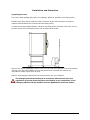
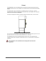
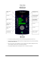
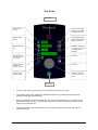
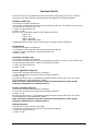
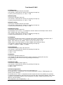
Service & Installation manual Light programmable oven with boiler Table of Contents Preface and terms of warranty Rating plate Installation and connection -Installation -Water connection -Drain connection -Electrical connection/survey of supply lines Exhaust Checking before use Annual service check Start menu Oven set-up -Set-up mode U1 to U9 -Set-up mode U10 to U15 Test functions -Test mode D0 to D6 -Test mode D7 to D15 -Test mode D16 to D20 -Test mode D21 to D28 -Test mode D29 to D47 User menu -User menu B1 to B6 -User menu B7 to B12 -User menu B13 to B20 -User menu B21 to B24 Error codes Survey of error codes Appendices -Appendix 1: WHIRLPOOL installation checklist -Appendix 2: WHIRLPOOL instruction checklist Notes GB -2- Page 3 4 5 6 7 8 9 10 11 12-13 14 15-17 16 17 18-23 19 20 22 23 24 25-29 26 27 28 29 30 31 32-34 32-33 34 35-36 Preface and Terms of Warranty You are now the owner of one of the leading oven products on the market. All WHIRLPOOL products are currently subjected to intensive product development, which ensures that the products always contain the latest technology and the most up-to-date and energy-saving methods of preparation. Furthermore, the WHIRLPOOL products are entirely up-to-date with the latest developments/ technology in terms of • • • • ERGONOMICS AND SAFETY SIMPLE AND LOGICAL OPERATION USER FRIENDLY DESIGN RELIABILITY AND SERVICE To ensure that our customers get an optimum and reliable product, all WHIRLPOOL units are passed through an extensive test program in which all functions are subjected to a continuous and extreme load. For optimum results Before you start using the oven, we recommend that you study the user’s manual thoroughly in order to be able to fully utilise the many facilities and to ensure optimum cooking results. Furthermore, by going through the manual, you will obtain a better understanding of the advanced technology and feel safer when using the oven in your daily work. Terms of warranty Provided that it has been registered on the WHIRLPOOL website, your new WHIRLPOOL oven is covered by a 48-month factory warranty. The warranty covers the oven cabinet and spare parts. Furthermore, there is a 10-year warranty on the exterior door glass. The period of warranty takes effect from the date of production. For further information on the warranty terms, please visit www.houno.com/warranty. The warranty does not include.... We especially draw your attention to the fact that the factory warranty does not cover glass parts such as interior door glass, lamp glass and halogen lamps, nor does it cover sealings. Furthermore, the factory warranty does not apply in the case of • defects that are due to the fact that installation has not been carried out in accordance with the WHIRLPOOL Installation & Service Manual at present in force (electricity, gas, water/drain, exhaust), • damage resulting from accidents, including damage caused by water, transport, misapplication or negligence, • defects and interruptions of operation that are the result of the oven not being handled/operated as specified in the user's manual. WHIRLPOOL cannot be made liable for indirect loss, including loss of profits. If you utilise all the technological facilities of this oven, you are guaranteed perfect results with only a minimum of resources. Enjoy your new WHIRLPOOL oven. Yours sincerely, WHIRLPOOL -3- Rating Plate When communicating with WHIRLPOOL, we kindly ask you inform us of the serial number of the oven that is stated on the approval plate. The approval plate is located on the right-hand corner post of the oven cabinet, as shown below. -4- Installation and Connection Unpacking the oven The oven is best handled while still in its wrapping. Wherever possible, use a lifting trolley. Introduce the lifting trolley under the lower cross tube of the stand and place a couple of wooden blocks between the cross tube and the lifting trolley. To achieve the best possible balance, introduce the lifting trolley from the front of the oven or from the motor side. Note that the oven can be lifted off the stand. Remove the original packaging from the oven. Do not remove the foil that covers the surfaces until the oven has been installed, as once the foil has been removed the surfaces are vulnerable to sharp objects such as tools. Remove all packaging material that secures the racks in the oven chamber. The packaging should be destroyed in accordance with national rules and regulations governing waste disposal. Information on the composition of the packaging material can be obtained from the WHIRLPOOL Customer Centre. -5- Installation and Connection Installing the oven To ensure that the oven functions correctly when installed, it should be placed upright and level (horizontally). This is measured at the front and side edge of the roof, and adjustment is made by means of the adjusting screws on the stand or on the legs of table models. The height of the oven can also be adjusted to fit the trolley for rack. Correct Wrong The oven should be placed 5 cm / 2 inch from the rear wall and the distance between the right side of the oven and the nearest wall or piece of furniture, etc. should be at least 7 cm / 2.75 inch. This is to ensure the necessary flow of cooling air to the oven. Strong sources of heat such as hotplates, tilting frying pans, deep fat fryers, etc. should not be placed near the oven, otherwise the warranty may cease to apply. (NSF) On an oven with stand, the distance to the floor must be at least 150 mm / 5.9 inch. Only 2½ threads must be visible on the adjustable feet. (NSF) On table models, the legs must be adjusted to allow a minimum clearance of 76 mm / 3 inch to the surface on which the oven stands. -6- Installation and Connection Water connection WHIRLPOOL ovens have one or two water connections. To facilitate cleaning and service, the oven should be connected with an approved flexible ¾’’ hose and the permanent installations should be fitted with a stop tap. Before connecting the oven to water, flush the tubes thoroughly. Hardness of the water: Conductivity: Water pressure: max. 3 dH min. 75 microsiemens min. 2.5 bar (36 PSI) dynamic pressure (when CombiWash on), max. 6 bar (87 PSI) Water flow: min. 12 l/m Water temperature: max. 20°C (68°F) Chloride concentration: max. 100 mg/litre Sulphate: max. 150 mg/litre The connection wire to the system should be fitted with a stop valve and a nonreturn valve. If the feeder is connected to the water distribution system with a flexible hose, this hose should be VA approved. If the water temperature exceeds 20°C / 68°F, problems with regard to ClimaOptima calibration and cooling of the oven may occur. Ovens with a steam generator must not be connected to a reversed osmosis plant, as this may cause problems with the reading of the water level in the steam generator. The water connection must be carried out by an authorised plumber in accordance with existing rules and regulations Clogged up water filters and dirt in the solenoid valves are not covered by the warranty. To ensure that the water quality is in conformity with the above requirements, the installation of a water filter in front of the water connection to the oven is recommended. The installation of a particle filter (0.25mm) is also recommended. In the case of two water connections, the following applies: 1) 1 connection for raw water for the condensation jet (cold water). Located at the back. 2) 1 connection for the steam generator and the jet in the oven chamber. Must meet the requirements applying to water supplied to household appliances; however, hot water with a temperature not exceeding 20°C / 68°F can be used. Located at the front. -7- Installation and Connection Drain connection From the factory, the WHIRLPOOL ovens are equipped with a drain system that removes surplus water from the oven chamber. This water may be condensed water from the products, or it may occur when the oven chamber is cooled down with cold water, or when the oven chamber is cleaned. Connection must be carried out by an authorised plumber, to an open or to a closed drain. It is recommended that a water outlet is available/established in the floor of the room where the oven is located. The drain must never end directly beneath the oven. The drain must be of stainless steel or an equally temperature-resistant material, have a diameter of at least 50 mm / 2 inch and a fall of at least 3° or 5%. -8- Installation and Connection Electrical connection/survey of supply lines The electrical connection must be carried out by an authorised electrician in accordance with existing rules and regulations. The wiring diagram is located in the motor compartment. The terminal for the electrical connection is located behind the right side plate. An approved plug outlet or a safety cutout must be located close to the oven so that the oven can be disconnected during installation and repair. The safety cutout must be able to cut off all poles with a total distance of break of at least 3 mm. Each of the two units in a stacked arrangement (CombiPlus) must have its own plug outlet or safety cutout. The warranty does not cover incorrect connection. Supply lines - survey (applies to all electric models ) (All cross sections in mm² ) AFO ----Æ 400V 3N ~ 50/60 Hz 400V 3 ~ 50/60 Hz 415V 3N ~ 50/60 Hz 440V 3 ~ 50/60 Hz 200V 3 ~ 50/60 Hz 230V 3 ~ 50/60 Hz 480V 3 ~ 50/60 Hz 208V 3 ~ 50/60 Hz 382, 395 382, 395 380, 393 383, 396 383, 396 384, 397 384, 397 375, 388 375, 388 376, 377, 378, 389, 390, 391 9 kW Fuse 18 kW Fuse 24 kW Fuse 36 kW Fuse 27 kW Fuse 60 kW Fuse 5x2,5 16A 5x4 35A 5x10 50A 5x10 63A 5x10 50A 5x25 100A 4x2,5 16A 4x4 35A 4x10 50A 4x10 63A 4x10 50A * * 5x2,5 16A 5x4 25A 5x10 50A 5x10 50A 5x10 50A 5x25 100A 4x2,5 16A 4x4 25A 4x10 50A 4x10 50A 4x6 35A * * 4x4 35A 4x16 63A 4x25 100A 4x35 125A 4x25 80A * * 4x4 25A 4x10 50A 4x25 80A 4x35 100A 4x25 80A * * 4x2,5 16A 4x4 25A 4x6 35A 4x10 50A 4x6 35A * * 4x4 25A 4x10 50A 4x25 80A 4x35 100A 4x25 80A * * 376, 377, 378, 389, 390, 391 379, 392 379, 392 380, 393 * Not possible Recommended supply line: H07RN-F When you connect the oven, you should • • • Follow the installation instructions and the information given on the rating plate. Comply with local rules and regulations. WHIRLPOOL recommends the use of a (Type B) RCD/RCCB. 300 mA -9- Exhaust The WHIRLPOOL ovens are equipped with an open/direct exhaust system that removes surplus humidity from the oven chamber. The exhaust system has an electrically operated damper. The exhaust tube can be connected to a ventilating system. In that case, a special extraction funnel is fitted to avoid suction directly from the oven chamber. This extraction funnel can be ordered from WHIRLPOOL. The scope of supply also includes a specially designed extraction hood, see illus. below. If an extraction hood is installed in the ceiling above the oven, it should project 50 cm over the front of the oven. The suction effect should be 400 – 800 m3/h. The ventilation motor can be controlled directly from the oven. This means that the ventilation starts when a program is started and runs for 10 minutes after the program is completed. The installation of the ventilation must comply with local rules and regulations. - 10 - Checking before Use The oven should be checked before you start using it. On the outside • • • Check that the oven has not been damaged in transit (dents, scratches, etc.) Check/adjust the height and check that the oven is placed level (horizontally) Check/adjust oven door • Connections • • • • • • • • • • • • • • Check for correct water connection Turn on water supply Check for leaks Turn off water supply Check and clean dirt filter Turn on water supply again Check hand shower Check for correct electrical connection Check connection to drip tray Check for correct mounting of drip tray Check for correct fall of hose from drip tray, and check for leaks Check for correct exhaust and drain connection Clean oven Apply steel oil • Oven chamber • • • Check that filter housing is mounted correctly Check interior light Clean oven • Operation panel • • Check and adjust, if necessary, each of the preset values Heat up the oven at 250°C for approx. 5 min. The installation checklist and the instruction checklist (appendices 1 and 2) should be filled in and returned to WHIRLPOOL 30 days after the installation, at the latest. - 11 - Annual Service Check Customer: Address: By: Postal code: Serial No of the oven: Model: 1. Connection: Functioning correctly Water connection – dirt filter (may need tightening) Electrical connection (may need tightening) Drain connection (may need tightening) Positioning of oven 2. Door: Closing device (may need adjusting) Catch (may need adjusting) Sealing (must be tight at 100°C steam or combi steam) Hinging (may need adjusting) Interior glass (hinging, fastening) Calibrate door sensor 3. Inside: Interior light Jets (may need cleaning) Fan (should rotate freely and be tightly fitted) Heating element (may need tightening) 4. Under oven: Drain system (check for leaks and blocks) Condensation jet and drain sensor Drip tray (clean hose for discharge connection piece) Drip slide on oven door 5. Motor room: Connection to heating elements Load distribution on phases Wire connection (overloading, bad connection, and tightening) Exhaust motor Fan motor (may need tightening) Frequency transformer (check regulation) ClimaOptima Cooling fan Filter for intake (may need cleaning) Cooling plate for solid-state relays (clean) Check for moisture - 12 - YES NO 6. Steam generator: Heating elements (check for leaks) Load distribution on phases Level sensor – to be cleaned Drain pump May need descaling Functioning correctly YES NO 7. Functional test: Components (use test function) Core temperature probe Operation modes CombiWash (clean jet head) Service engineer: Date and signature Parts to be replaced at 12-, 24- and 36-month service intervals: 12-month inspection Follow the annual service check (see above). Change: Door seal Light bulbs Gasket for lamp glass Nozzles Bearing for nozzle arm Update software 24-month inspection Follow the annual service check (see above). Change: Door seal Light bulbs Gasket for lamp glass Nozzles Main contactor Spring for handle Bearing for nozzle arm Update software - 13 - 36-month inspection Follow the annual service check (see above). Change: Door seal Light bulbs Gasket for lamp glass Nozzles Exhaust for damper motor Detergent and rinse pump Nozzle arm assy Update software Start Menu Main switch Change oven temperature with turn switch HOT AIR selected if control lamp on COMBI STEAMING selected if upper or middle control lamp is on. REHEATING is selected if lower control lamp is on. Change time with turn switch Core temperature on C and K models. Injection time on B model. Steaming on C and K, preheating on B Program key Exhaust open if control lamp on Step key Fan speed can be set between 20 and 100%. Control lamp is on when speed < 100. Alarm key Turn switch Start/Stop Set temperature (press temperature key, temperature flashes, set temperature with turn switch, press temperature key again to save). Set time (press time key, time flashes, set time with turn switch). Set core temperature (press core temperature key, set temperature with turn switch). C and K models only. Set injection time (press injection key, time flashes, set injection time with turn switch). B model only. - 14 - Oven set-up Main switch Display shows setting Press HOT AIR and STEAMING for 2 sec. Not active Possible to change to "d" test mode with combi steam key Display shows "U" No. Press STEAMING/ PREHEATING and HOT AIR for 2 sec. Display shows description of "U" function Not active Display shows setting Not active Confirmation of special settings Select "U" settings with turn switch Not active To enter set-up mode, press hot-air key and steaming/preheating key for 2 sec. To leave set-up mode, turn switch to the left. Change between set-up and test mode by pressing combi-steam key. The set-up mode is only intended for service engineers who wish to change the set-up of the computer control of the oven model in question. The program display shows a description of the "U" function in question. - 15 - Set-up Mode U In the set-up function, it is possible to set the oven controller to match the mechanical set-up and the choice of software. If the set-up has been changed in U1, U4 or U15, the oven will be reset. U1 Oven model The setting should be set to 1( by pressing the step key ). You press the temperature key to select a PassThrough model (two doors). 1= one door (standard) 2= two doors When you have selected the oven model, confirm by pressing the alarm key if the control lamp flashes. After that, the controller initializes. NOTE: ALL settings and programs are reset. U2 Oven size You choose the oven size by pressing the step key: 0-7.0= 6, 1= 8, 2= 10, 3= 12, 4= 16, 5= 20, 6= 2 x 10, 7= 2 x 14. The oven size you have chosen is shown in the field next to the temperature key. U3 CombiWash You activate or deactivate CombiClean by pressing the step key. 0=OFF, 1=ON. U4 Temperature scale You choose between Celsius and Fahrenheit as scale of temperature by pressing the step key. 0= Celsius 1= Fahrenheit. You can ”even out” the current temperature by pressing the temperature key. 0=OFF, 1=ON When you have chosen the temperature scale, confirm by pressing the alarm key if the control lamp flashes. After that, the controller initialises. NOTE: ALL settings and programs are reset. U5 Not in use U6 Low-temperature steaming You activate and deactivate low-temperature steaming by pressing the step key. 0= OFF, steaming only possible at 100°C, 1= ON, steaming only possible between 30°C and 120°C. U7 Preheating at 300°C You activate and deactivate preheating by pressing the step key. 0= OFF, 1= ON. NOTE: Preheating at temperatures above 250°C is only possible for max. 15 minutes. U8 Setting water level sensor When you press the temperature key, the water level value starts flashing and can then be set between 40 and 80 (default 70). If the conductivity of the water is low, set the water level higher. U9 Automatic restart You activate and deactivate automatic restart by pressing the step key. 0= OFF, 1= 10 minutes, 2= 30 minutes, 3= 60 minutes. This means that if there is a power cut, the program that was interrupted will be reassumed provided that the power returns within the time set. U10 Programs You activate the program mode by pressing the step key. - 16 - 0= OFF, 1= 10 programs with 3 process steps. NOTE: It is still possible to activate the cleaning program even though the program mode is not active. 0= OFF. U11 Core temperature probe You activate and deactivate the core temperature probe by pressing the step key. 0= OFF, 1= ON. U12 Drain cooling You activate and deactivate drain cooling by pressing the step key. 0= OFF, 1= ON. U13 Timer start You activate or deactivate timer start by pressing the step key. 0= OFF, 1= ON. U14 Demo You activate or deactivate the demo mode by pressing the step key. 0= OFF, 1= ON. NOTE: If the demo mode is on (1= ON), the oven will run without heating elements and steam generator being switched on. When the oven starts, it will let you know whether the demo mode is on. U15 Initialising You reset the controller by pressing the alarm key. - 17 - Test Mode Main switch Display shows setting For test mode, press HOT AIR and COMBI STEAMING for 2 sec. Display shows setting For test mode, press COMBI STEAMING and HOT AIR for 2 sec. Display shows "d" No. Possible to change to "U" setting by pressing STEAMING/PREHEATING Display shows a description of the "d" function Not active Display indicates whether the function is active Not active Activates each function briefly Possible to choose a "d" function with turn switch Not active To enter test mode, press hot-air key and combi-steam key for 2 sec. To exit test mode, turn switch left. Change between set-up mode and test mode by pressing steaming/preheating key. How to operate the selected component: You turn the component on (1) and off (2) by pressing the step key. Or, you press the alarm key, and the component is active for as long as you press the key. The set-up mode is only intended for service engineers who wish to test the various modes/functions. - 18 - Test Mode D0-D6 In the test mode, it is possible to activate all electrical components. This is very useful in connection with fault detection and the testing and adjusting of replacement parts. D0 Main contactor(s) This function activates contactor K1. You activate or deactivate the function by pressing the step key. The function can, however, only be activated when the fan is on. To pulse, press the alarm key. 0= OFF, 1= ON. Status for the main alarms appear in the display as follows: Digit 1 fan Digit 2 oven Digit 3 generator Digit 4 Solid State Relay If ER28 appears, the alarm sensor circuit board or wiring harness is defective. D1 Oven heat This function activates contactor K2. You activate or deactivate the function by pressing the step key. Humidity pulsing is possible by pressing the alarm key. 0= OFF, 1= ON. D2 Steam generator heat This function activates contactor K3. You activate or deactivate the function by pressing the step key. However, this function can only be activated when there is water in the steam generator. To pulse, press the alarm key. 0= OFF, 1= ON. D3 Fan, right-hand, high/low This function activates the frequency exchanger. You can test the speed of the motor by pressing the step key. 0= OFF, 2= ON By pressing the time key, it is possible to adjust the speed of the motor from 0 to 100%. The RPM appears in the temperature display. Note: The main contactor K1 must be active for this function to work, as the frequency transformer is connected via K1 D4 Fan, left-hand, high/low This function activates the frequency exchanger. You can test the speed of the motor by pressing the step key. 0= OFF, 2= ON By pressing the time key, it is possible to adjust the speed of the motor from 0 to 100%. The RPM appears in the temperature display. Note: The main contactor K1 must be active for this function to work, as the frequency transformer is connected via K1 D6 Solenoid valve This function activates solenoid valve MV1. You activate or deactivate the function by pressing the step key To pulse, press the alarm key. 0= OFF, 1= ON. - 19 - Test Mode D7-D15 D7 Filling valve This function activates solenoid valve MV2. You activate or deactivate the function by pressing the step key. To pulse, press the alarm key. 0= OFF, 1= ON. D8 Drain pump This function activates motor M2. You activate or deactivate the function by pressing the step key. To pulse, press the alarm key. 0= OFF, 1= ON. D9 Drain cooling This function activates solenoid valve MV3. You activate or deactivate the function by pressing the step key. To pulse, press the alarm key. 0= OFF, 1= ON. D10 Damper motor This function activates motor M3. In the display next to ”Time”, it is possible to read the status of the damper motor switch. OFF= damper open, ON= damper closed. You activate or deactivate the function by pressing the step key. To pulse, press the alarm key. 0= OFF, 1= ON. D11 Exhaust This function activates the outlet for controlling the external ventilation, terminals 4 and 5. In the display next to ”Time”, it is possible to read which outlet is active. OFOF= both outlets are off, ONOF= outlet 4 is active and outlet 5 is off. OFON= outlet 4 is off and outlet 5 is active. ONON= both outlets are active. You activate or deactivate the function by pressing the step key. 0= OFOF, 1= OFON, 2= ONOF, 3= ONON. D12 Cooling fan This function activates motors M7 and M7A. You activate or deactivate the function by pressing the step key. To pulse, press the alarm key. 0= OFF, 1= ON. D13 Buzzer This function activates buzzer H2. You activate and deactivate this function at high volume by pressing the step key. It is possible to pulse at low volume by pressing the alarm key. 0= OFF, 1= ON. D14 Interior light This function activates interior light H1. You activate or deactivate the function by pressing the step key. To pulse, press the alarm key. 0= OFF, 1= ON. D15 Oven temperature Here it is possible to read the current oven temperature, P1. In the field next to ”Temperature”, the current temperature is shown. If ERR appears, the sensor circuit is defective. In the field next to ”Time”, an adjustment value between 80 and 120 (default 100) is shown. To adjust the temperature, press the time key until the digit in the display flashes. Then adjust upwards or downwards until the correct temperature is shown. Finally, press the time key again to save the setting. The temperature can be adjusted by +- 10 - 20 - Test Mode D16-D20 D16 Core temperature This function is not available on B models. C and K models can use only one core temperature probe, it is possible, however, to test core temperature probes 1 and 2. Here it is possible to read the current temperature of the core temperature sensor, P2 + P2A. In the field next to ”Temperature”, the current temperature is shown. If ERR appears, the sensor circuit is defective. In the field next to ”Time”, an adjustment value between 80 and 120 (default 100) is shown. To adjust the temperature, press the time key until the digit in the display flashes. Then adjust upwards or downwards until the correct temperature is shown. Finally, press the time key again to save the setting. The temperature can be adjusted by +- 10°C. You change between the various measuring points of the core temperature probe by pressing the step key. 1= Core temp.probe 1, point 1, 2= Core temp.probe, point 2, 3= Core temp.probe 1, point 3. 4= Core temp.probe 2, point 1, 5= Core temp.probe, point 2, 6= Core temp.probe 2, point 3. D17 Steam generator temperature Here it is possible to read the current steam generator temperature, P3. In the field next to ”Temperature”, the current temperature is shown. If ERR appears, the sensor circuit is defective. In the field next to ”Time”, an adjustment value between 80 and 120 (default 100) is shown. To adjust the temperature, press the time key until the digit in the display flashes. Then adjust upwards or downwards until the correct temperature is shown. Finally, press the time key again to save the setting. The temperature can be adjusted by +- 10°C. D18 Drain temperature Here it is possible to read the current steam generator temperature, P4. In the field next to ”Temperature”, the current temperature is shown. If ERR appears, the sensor circuit is defective. In the field next to ”Time”, an adjustment value between 80 and 120 (default 100) is shown. To adjust the temperature, press the time key until the digit in the display flashes. Then adjust upwards or downwards until the correct temperature is shown. Finally, press the time key again to save the setting. The temperature can be adjusted by +- 10°C (approx. 0.5°C per step). D20 Door sensor Here it is possible to read the status of and calibrate door sensor 1 = SE1 and 2 = SE1A. You change between door sensor 1 and 2 by pressing the step key (if 2 door sensors have been selected in U1). After some time, the text “DOOR SENSOR” changes to show the status of the sensor: >CLOSED<, >OPEN<, >SENS ERROR<. You start the calibration by pressing the exhaust key. How to calibrate: 1. Press exhaust key 2. >CLOSE DOOR< flashes 3. Close the door 4. Press exhaust key 5. >OPEN DOOR< flashes 6. Open door in first step 7. Press exhaust key 8. >CALIB OK< or >CALIB ERR< appears In the display next to the temperature key, it is possible to read the current value (0 – 120). In the display next to the time key, it is possible to read the set point. - 21 - Test Functions D21-28 D21 Water level Here it is possible to read the status of SE2. In the display next to ”Time”, the conductivity is shown and it is indicated whether the water level is high or low XX|LO= low water level, XX|HI= high water level. XX = conductivity of the water. Default setting is approx. 80 with no water and 40.60 with water. The better the conductivity, the lower the measured value. D22 Thermo-switch oven Here it is possible to read the status of Q1 and Q1A. In the display next to ”Time”, it is shown whether the circuit is connected or disconnected. OF= disconnected ON= connected. In the event of defects, it is possible to reset thermo-switches Q1 and Q2 that are located at the bottom of the oven below the operation panel. Note: Q2 is only found in ovens with 2 fan motors (1.16 and 1.20). Q1 and Q1A are series connected which is why there is only one input signal. D23 Thermo-switch fan Here it is possible to read the status of S2 and S2A In the display next to ”Time”, it is shown whether the circuit is connected or disconnected. OF= disconnected ON= connected. In the event of defects, wait for 10 – 20 minutes, then try again. Note: Q2 is only found in ovens with 2 fan motors (1.16 and 1.20). S1 and S1A each have their own input on the IO board hence 2 x status (On On / OF OF / On OF / OF On). D24 Damper switch Here it is possible to read the status of M3. In the display next to ”Time”, it is possible to read the status of the damper motor switch. OF= damper open, ON= damper closed. D27 Pump for detergent Only possible on ovens with CombiWash This function activates pump M5. You activate or deactivate the function by pressing the step key. To pulse, press the alarm key. 0= OFF, 1= ON. D28 Pump for rinse aid Only possible on ovens with CombiWash This function activates pump M6. You activate or deactivate the function by pressing the step key. To pulse, press the alarm key. 0= OFF, 1= ON. - 22 - Test Mode D29-D47 D29 CombiWash water Only possible on ovens with CombiWash. This function activates solenoid valve MV4. You activate or deactivate the function by pressing the step key. To pulse, press the alarm key. 0= OFF, 1= ON. D34 Water pressure sensor Here it is possible to read the status of P7. OF|HI= water pressure adequate, ON|LO= water pressure inadequate. D36 Steam generator thermo-switch Here it is possible to read the status of Q3 In the display next to ”Time”, it is shown whether the circuit is connected or disconnected. OF= disconnected ON= connected. In the event of defects in the oven, it is possible to reset thermo-switch Q3 which is located at the bottom of the oven below the operation panel. D37 Motor RPM 1 Here it is possible to read the number of revolutions for fan motor 1. The number of revolutions is shown in the display next to the temperature key. D38 Motor RPM 2 Available on 1.16 and 1.20 models only. Here it is possible to read the number of revolutions for fan motor 2. The number of revolutions is shown in the display next to the temperature key. D46 Temperature CPU board Here it is possible to read the temperature of the CPU board. In the display next to ”Temperature”, the temperature of the CPU board is shown. Max 60°C. D47 Temperature IO board Here it is possible to read the temperatures of the IO board. In the display next to ”Temperature”, the temperature of the IO board is shown. Max 60°C. - 23 - User Menu Main switch Display shows setting Not active Display shows setting Not active Display shows "b" No. Not active Display shows description of "b" function Not active Display shows setting Not active Press key for 5 sec. to access user menu Turn switch Start/Stop To enter user menu, press alarm key for 5 sec. To exit user menu, turn the switch to the left. The user menu can be operated by the end-customer as well as by the service engineer. - 24 - User Menu B1-B7 B1 Save presettings In this function, you save the preset time and temperature. If, for instance, the end user uses HOT AIR at 180°C for 30 minutes, the standard setting can be changed as follows: 1. 2. 3. 4. Change time and temperature. Enter user menu (keep pressing alarm key for 5 sec.) Select B1 (save presettings). Press alarm key to accept. You can only save the settings when the control lamp next to the alarm key flashes. B2 Timer start (Please see user manual) B3 Sound level low In this function, you adjust the sound that is heard when a key is activated. The sound level can be adjusted from 0 to 9 (0 is no sound at all). You adjust the sound level by pressing the step key. B4 Sound level high In this function, you adjust the sound that comes from the alarm. The sound level can be adjusted from 1 to 9 (1 is very low). You adjust the sound by pressing the step key. B5 Sound frequency In this function, you adjust the sound frequency. The sound frequency can be adjusted from 1 to 9. You adjust the sound by pressing the step key. You test the sound by pressing the alarm key. B6 Interior light In this function, you adjust the interior light. The light can be set at 0 or 5. 0= Light is always on. 5= Light goes out when the oven has been idle for 5 minutes. You adjust the interior light by pressing the step key. B7 Current temperature In this function, you choose whether the oven should display the current temperature or the preset temperature. You choose between 0 and 1 0= The preset temperature is shown. 1= The current temperature is shown. You change the setting with the step key. - 25 - User Menu B8-B13 B8 Exhaust In this function, you choose whether the oven should start up the extraction hood. 0= Extraction hood not controlled by oven 1= Extraction hood runs for 10 minutes after oven has stopped. This applies to an extraction hood mounted on the oven as well as for an external extraction hood. B9 Time graphics In this function, you determine whether the oven should be able to show graphically how long time has passed of a cooking sequence. You choose between 0 and 1. 0= No graphics 1= Graphics, for instance ”llllll------”, appear You change the setting with the step key. B10 Minutes In this function, you set the minutes of the oven’s clock. 1. Press the key next to the temperature display (digit flashes). 2. Turn the switch to the desired setting of minutes. 3. Press the key next to the temperature display (digit stops flashing) You can set the minutes from 0 to 59. The oven’s clock may appear as screen saver. B11 Hours In this function, you set the hours of the oven’s clock. 1. Press the key next to the temperature display (digit flashes) 2. Turn the switch to the desired setting of hours. 3. Press the key next to the temperature display (digit stops flashing) You can set the hours from 0 to 23. The oven’s clock may appear as screen saver. B12 Day/weekday In this function, you set the day of the month and of the week. 1. Press the key next to the temperature display (digit flashes) 2. Turn the switch to the desired day of the month (1-31). 3. Press the key next to the temperature display (digit stops flashing) 4. Press the key next to the time display (digit flashes) 5. Turn the switch to the desired day of the week (1-7). 6. Press the key next the time display (digit stops flashing) You select automatic updating to summer time. 0= No automatic updating to summer time. 1= Automatic updating to summer time. If you choose not to have the oven update to summer time automatically, you cannot set the weekday. Automatic updating to summer time only functions correctly in Western Europe. B13 Month In this function, you set the month. 1. Press the key next to the temperature display (digit flashes). 2. Turn the switch to the desired month. 3. Press the key next to the temperature display (digit stops flashing). You can set the month from 1 to 12. - 26 - User Menu B14-B21 B14 year In this function, you set the year. 1. Press the key next to the temperature display (digit flashes). 2. Turn the switch to the desired setting. 3. Press the key next to the temperature display (digit stops flashing). You set the year from 6 to 20. B15 CombiWash In this function, you activate or deactivate CombiWash. 0= Manual cleaning 1= CombiWash Press step key to change setting. B16 Pulsing interval, reheating In this function, you set the pulsing time in the reheating mode. 1. Press the key next to the temperature display (digit flashes). 2. Turn the switch to the desired time. 3. Press the key next to the temperature display (digit stops flashing) You set the time from 5 – 50 sec. B17 Pulsing interval, Combi Steam 1 In this function, you set the pulsing time for Combi Steam 1. 1. Press the key next to the temperature display (digit flashes). 2. Turn the switch to the desired time. 3. Press the key next to the temperature display (digit stops flashing) You set the time from 2 to 50 sec. B18 Pulsing interval, Combi Steam 2 In this function, you adjust the pulsing time for Combi Steam 2. 1. Press the key next to the temperature display (digit flashes). 2. Turn the switch to the desired time. 3. Press the key next to the temperature display (digit stops flashing) You set the time from 1 sec. to the number of seconds specified to be the pulsing time for Combi Steam 1. B19 Save all (Backup) In this function, you save set-up and programs to the IO board for subsequent restoration. This can be used as backup when set-up and programs are correct. Press alarm key to save. B20 Restore all In this function, you restore set-up and programs you have saved earlier. B21 Restore original In this function, you restore the original programs from 0 to 4. 1. Press step key to select program. 2. Press alarm key when program has been found. - 27 - User Menu B22-B24 B22 Screen saver In this function, you set the time that should pass until the clock appears in the display. Press step key to select time. 0= no screen saver 1= 10 sec. 2= 30 sec. 3= 60 sec. 4= 180 sec. 5= 600 sec. The screen saver appears when the oven has been idle for a particular period of time. B23 Language In this function, you change the language of the computer. Press step key and select 1 to 9. There are two language variants: A – B (see below). 1 2 3 4 5 6 7 8 9 A DANISH ENGLISH SWEDISH FINNISH GERMAN SPANISH FRENCH ITALIAN DUTCH B ENGLISH CROATIAN SLOVENE ESTONIAN HUNGARIAN RUSSIAN CZECH - To change the language, you need to update again (see B24). B24 Software update In this function, you update the computer software by means of a special memory key (not a USB key). 1. Insert memory key. 2. Press alarm key to view software version and language variants. 3. Press step key to select language variant. 4. Press alarm key again to start updating process. The software version of the oven in question is also shown in the start-up sequence when the oven is switched on. - 28 - Error codes Main switch Display shows error "Er" No Display shows description of error Turn switch Start/Stop All keys can be used to acknowledge an error message. - 29 - Error codes Error code 3: GENRA HOT Error code 4: OVEN HOT Error code 5: FAN HOT Error code 6: DRAIN > 75 Error code 7: OVEN SENS Error code 8: PROBE SENS Error code 9: GENER SENS Error code 10: DRAIN SENS Error code 11: WATER SHOR Error code 12: SSR HOT Error code 13: GENER > 130 Error Error Error Error Error FAN SPEED CPU HOT IO BRD HOT DATA ERROR WRONG LANG code code code code code 14: 15: 16: 18: 19: Error code 20: NO COM IO Error code 22: Error code 23: NO RESTART OVEN WARM Error code 24: DRAIN ERR Error code 25: PROBE ERR Error Error Error Error Error Error Error ALARM ERR DOOR SENS WATER PRES IO BRD HOT WRONG SW DAMPER ERR 24 V ERROR code code code code code code code 28: 29: 34: 40: 43: 44: 45: Generator too hot (Generator thermoswitch has tripped. Reconnect by pressing button under oven.) Oven too hot (Oven chamber thermoswitch has tripped. Reconnect by pressing button under oven.) Fan too hot (Thermoswitch in motor has tripped. Wait for 10 minutes and try again. Drain too hot (Drain temperature has been above 75°C for more than 5 min. Check that jet in drain is working.) Oven sensor defective (Temperature sensor in oven chamber not working properly.) Core temp. probe not connected (A program using core temp. probe has been selected but probe has not been connected.) Generator sensor defective (Temperature sensor in generator not working.) Drain sensor defective (Sensor in drain not working. Oven can still be used.) Water shortage (Steam generator was not filled within two minutes. Check that the water has been turned on.) SSR too hot (Solid-state relay too hot.) Generator too hot (Temperature in steam generator higher than 130°C. If fault recurs, descale generator) Fan running too slow CPU board too hot (> 60°C) IO board too hot (> 60°C) Error in set-up data Wrong language Internal defect (Failure in communication between computer and IO board.) Restart not possible (Oven has been without power too long.) Oven too hot at CombiWash start-up Draining failure (Drain blocked or failure of drain pump. Water level in generator still high after 10 seconds of draining.) Core temperature probe defective (1, 2 or 3 of the elements in the core temperature probe defective.) Configuration error in main alarms (3, 4, 5, 12) (warning) Wrong door sensor signal (warning) Water pressure too low (Check that water is turned on.) Temperature in IO board critical (Warning after program run.) Wrong software version (Visual Cooking I oven) Failure during initialisation of exhaust at oven start-up 24 V missing or failure of main contactor output - 30 - Appendix No 1 WHIRLPOOL INSTALLATION CHECKLIST FOR VISUAL COOKING OVENS To be filled out at each installation of a WHIRLPOOL oven. In order for the oven to qualify for warranty, this check list must be filled out by the service engineer installing the oven and returned to WHIRLPOOL within 30 days of the date of installation. Serial no.:_________________________________ Installed by:____________________________________________________ Date of installation:________________/_____/__________ The installation was carried out not carried out on the basis of the requirements specified in the service and installation manual, please tick. If the measurements do not correspond with the values stated in the service and installation manual, your WHIRLPOOL distributor should be notified. We confirm that the installation has been carried out on the basis of the attached check list and in compliance with the rules/requirements applying in the country/area in question. When the oven was handed over, it was free from any kind of defect. --------------------------------------Signature / date – service engineer -------------------------------------Signature / date - customer - 31 - Access to the oven: Recommended distance for service and for installation near other heatgenerating appliances (all oven sizes). All ovens Left side minimum Rear side minimum 50 mm (2”) 50 mm (2”) Right side minimum 400 mm (15”) Distance measured in mm Drain connection: Yes No Yes No Yes No Heat-resistant drain tube connected. Fall of at least 3º or 5%. CombiPlus fitted with open drain for both ovens. The drain must never end directly under the oven. Voltage and water supply: (Please insert the measured value) Voltage measured at: Water pressure measured at: (min. 2 bar/28,5 psi max. 6 bar/88 psi). Does the voltage on site comply with the voltage stated on the approval plate? Dirt filter fitted. Function test: All electrical connections are tight. All water connections are tight and have been fastened. All functions are operable. All equipment is operable. - 32 - Appendix No 2 WHIRLPOOL INSTRUCTION CHECKLIST FOR VISUAL COOKING OVENS To be filled out for each installation of a WHIRLPOOL oven. In order for the oven to be qualified for warranty, this check list must be filled out and returned to WHIRLPOOL within 30 days of the date of instruction. Customer:_______________________________________________ Address:________________________________________________________ _______________________________________________________________ _______________________________________________________________ Tel.:_____________________________________ Fax:_____________________________________ E-mail address:____________________________ Serial no.:_________________________________ Instruction carried out by:__________________________________________ Date of instruction:_________________/_____/__________ (Please tick the appropriate box) Yes No The customer has been instructed in the manual use and programming of the oven. The customer has been instructed in the daily cleaning of the oven. The customer has been instructed in the maintenance of the oven. When the oven was handed over, it was free from any kind of defect. The handling, maintenance and cleaning of the oven have been explained to the customer. --------------------------------------Signature / date – Sales person - 33 - -------------------------------------Signature / date - Customer Notes: _________________________________________________________________________ _________________________________________________________________________ _________________________________________________________________________ _________________________________________________________________________ _________________________________________________________________________ _________________________________________________________________________ _________________________________________________________________________ _________________________________________________________________________ _________________________________________________________________________ _________________________________________________________________________ _________________________________________________________________________ _________________________________________________________________________ _________________________________________________________________________ _________________________________________________________________________ _________________________________________________________________________ _________________________________________________________________________ _________________________________________________________________________ _________________________________________________________________________ _________________________________________________________________________ _________________________________________________________________________ _________________________________________________________________________ _________________________________________________________________________ _________________________________________________________________________ _________________________________________________________________________ _________________________________________________________________________ _________________________________________________________________________ _________________________________________________________________________ _________________________________________________________________________ - 34 - Notes: _________________________________________________________________________ _________________________________________________________________________ _________________________________________________________________________ _________________________________________________________________________ _________________________________________________________________________ _________________________________________________________________________ _________________________________________________________________________ _________________________________________________________________________ _________________________________________________________________________ _________________________________________________________________________ _________________________________________________________________________ _________________________________________________________________________ _________________________________________________________________________ _________________________________________________________________________ _________________________________________________________________________ _________________________________________________________________________ _________________________________________________________________________ _________________________________________________________________________ _________________________________________________________________________ _________________________________________________________________________ _________________________________________________________________________ _________________________________________________________________________ _________________________________________________________________________ _________________________________________________________________________ _________________________________________________________________________ _________________________________________________________________________ _________________________________________________________________________ _________________________________________________________________________ - 35 -