1
About This Guide
This section discusses the audience, organization, and conventions of this installation and
configuration guide.
Cisco documentation and additional literature are available in a CD-ROM package, which
ships with your product. The Documentation CD-ROM, a member of the Cisco Connection
Family, is updated monthly. Therefore, it might be more current than printed
documentation. To order additional copies of the Documentation CD-ROM, contact your
local sales representative or call customer service. The CD-ROM package is available as a
single package or as an annual subscription. You can also access Cisco documentation on
the World Wide Web at http://www.cisco.com, http://www-china.cisco.com, or http://
www-europe.cisco.com.
If you are reading Cisco product documentation on the World Wide Web, you can submit
comments electronically. Click Feedback in the toolbar and select Documentation. After
you complete the form, click Submit to send it to Cisco. We appreciate your comments.
Audience
This publication is designed for the person installing Cisco 1600 series routers who should
be familiar with electronic circuitry and wiring practices and have experience as an
electronic or electromechanical technician.
Use this guide together with the quick-reference installation guide and with the Cisco 1600
Series Software Configuration Guide that came with your router.
About This Guide xi
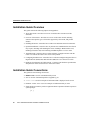
Installation Guide Overview
Installation Guide Overview
This guide contains the following chapters and appendices:
•
About This Guide—Provides an overview of and describes conventions of this
document.
•
Overview of the Router—Provides an overview of the router models, including
connector descriptions, types of networks supported by each model, and product
features.
•
•
Installing the Router—Describes how to make LAN and WAN network connections.
•
Troubleshooting—Describes how to isolate problems you might encounter with the
router or to rule out the router as the source of the problem.
•
Configuring the ISDN Line—Describes how to order and configure Integrated Service
Digital Network (ISDN) Basic Rate Interface (BRI) for Cisco 1600 series routers.
•
Hardware Specifications and Cable Pinouts—Contains router hardware specifications
and pinouts for cables used with Cisco 1600 series routers.
Optional Installations—Describes how to perform some installations that not all users
may require, including wall-mounting the router, installing a WAN interface card,
installing a Flash PC card, and connecting an ISDN telephone to a Cisco 1604.
Installation Guide Conventions
This guide uses the following conventions:
•
•
•
•
•
Boldface font is used for commands and keywords.
Italic is used for command input that is supplied by you.
Screen font is used for examples of information that is displayed on the screen.
Boldface screen font
is used for examples of information that you enter.
Square brackets contain keywords or arguments that are optional or default responses to
system prompts:
[ x ]
xii
Cisco 1600 Series Router Hardware Installation Guide
Installation Guide Conventions
•
Braces contain a choice of keywords (represented by x below) that are separated by
vertical bars:
{x|x|x}
•
Angled brackets contain characters that are not echoed on the screen, such as
passwords:
<password>
•
The key labeled Control is represented by ^ or Ctrl-D. For example, when you read ^D
or Ctrl-D, you should hold down the Control key while you press the D key.
Note Means reader take note. Notes contain helpful suggestions or references to material
not contained in this guide.
Caution Means reader be careful. In this situation, you might do something that
could result in equipment damage or loss of data.
Warning Means danger. You are in a situation that could cause bodily injury.
Before you work on any equipment, you much be aware of the hazards involved
with electrical circuitry and familiar with standard practices for preventing
accidents.
To see translations of the warnings that appear in this document, refer to the regulatory
compliance and safety information document that came with your router.
Waarschuwing Dit waarschuwingssymbool betekent gevaar. U verkeert in een situatie die
lichamelijk letsel kan veroorzaken. Voordat u aan enige apparatuur gaat werken, dient u
zich bewust te zijn van de bij elektrische schakelingen betrokken risico's en dient u op de
hoogte te zijn van standaard maatregelen om ongelukken te voorkomen.
Varoitus Tämä varoitusmerkki merkitsee vaaraa. Olet tilanteessa, joka voi johtaa
ruumiinvammaan. Ennen kuin työskentelet minkään laitteiston parissa, ota selvää
sähkökytkentöihin liittyvistä vaaroista ja tavanomaisista onnettomuuksien
ehkäisykeinoista.
About This Guide xiii
Installation Guide Conventions
Attention Ce symbole d'avertissement indique un danger. Vous vous trouvez dans une
situation pouvant causer des blessures ou des dommages corporels. Avant de travailler sur
un équipement, soyez conscient des dangers posés par les circuits électriques et
familiarisez-vous avec les procédures couramment utilisées pour éviter les accidents.
Warnung Dieses Warnsymbol bedeutet Gefahr. Sie befinden sich in einer Situation, die zu
einer Körperverletzung führen könnte. Bevor Sie mit der Arbeit an irgendeinem Gerät
beginnen, seien Sie sich der mit elektrischen Stromkreisen verbundenen Gefahren und der
Standardpraktiken zur Vermeidung von Unfällen bewußt.
Avvertenza Questo simbolo di avvertenza indica un pericolo. La situazione potrebbe
causare infortuni alle persone. Prima di lavorare su qualsiasi apparecchiatura, occorre
conoscere i pericoli relativi ai circuiti elettrici ed essere al corrente delle pratiche standard
per la prevenzione di incidenti.
Advarsel Dette varselsymbolet betyr fare. Du befinner deg i en situasjon som kan føre til
personskade. Før du utfører arbeid på utstyr, må du vare oppmerksom på de faremomentene
som elektriske kretser innebærer, samt gjøre deg kjent med vanlig praksis når det gjelder å
unngå ulykker.
Aviso Este símbolo de aviso indica perigo. Encontra-se numa situação que lhe poderá
causar danos físicos. Antes de começar a trabalhar com qualquer equipamento, familiarizese com os perigos relacionados com circuitos eléctricos, e com quaisquer práticas comuns
que possam prevenir possíveis acidentes.
¡Advertencia! Este símbolo de aviso significa peligro. Existe riesgo para su integridad
física. Antes de manipular cualquier equipo, considerar los riesgos que entraña la corriente
eléctrica y familiarizarse con los procedimientos estándar de prevención de accidentes.
Varning! Denna varningssymbol signalerar fara. Du befinner dig i en situation som kan
leda till personskada. Innan du utför arbete på någon utrustning måste du vara medveten om
farorna med elkretsar och känna till vanligt förfarande för att förebygga skador.
xiv
Cisco 1600 Series Router Hardware Installation Guide
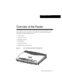
C H A PT E R
1
Overview of the Router
Cisco 1600 series routers are a family of small desktop routers that link small-to-medium
remote Ethernet LANs to regional and central offices over multiple WAN connections.
This chapter contains the following sections:
Router Features
WAN Interface Cards
Rear-Panel Connectors
Router Memory
Unpacking the Router
Equipment That You Must Provide
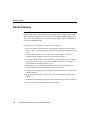
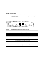
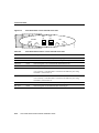
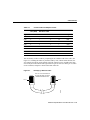
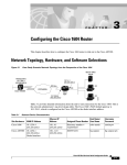
Figure 1-1
Cisco 1600 Series Router Front (All Models)
C
S Eisco 160
RI E 0
S
H6861
•
•
•
•
•
•
Overview of the Router 1-1
Router Features
Router Features
Note The Cisco 1600 series routers are either run-from-flash (RFF) or run-from-RAM
(RFR) models. Router model names with an R are RFR routers; all other models are RFF.
In this document, model names without an R refer to both RFF and RFR models, except
where noted. The “Router Memory” section later in this chapter describes the differences
between RFF and RFR models.
Listed below are some features of the Cisco 1600 series routers:
1-2
•
One or two Ethernet LAN connections, using either the 10BaseT or AUI LAN ports.
(Refer to Table 1-1 for more information about the LAN connections supported by each
model.)
•
One fixed WAN port (except for the Cisco 1605). (Refer to Table 1-1 for more
information about the WAN connections supported by each model.)
•
One slot for a WAN interface card, for flexibility in choosing WAN connections that the
router supports. (Refer to the section “WAN Interface Cards” later in this chapter for
more information about WAN interface cards.)
•
Flash memory PC card (PCMCIA-compatible), which can be preconfigured by a
network administrator and installed in the router at a remote site.
•
Console port, which supports router management using a terminal or a PC with terminal
emulation software.
•
Router management over the network using Simple Network Management Protocol
(SNMP).
•
•
AutoInstall for downloading configuration files automatically over a WAN connection.
Security slot for Kensington-compatible lockdown cable.
Cisco 1600 Series Router Hardware Installation Guide
Router Features
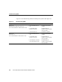
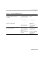
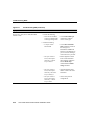
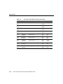
Table 1-1 describes in detail the types of LAN and WAN connections that are supported by
each of the five router models.
Table 1-1
Network Connections Supported By Cisco 1600 Series Routers
Model
LAN Interface(s)
Fixed WAN Interface
Cisco 1601
• One 10BaseT
Serial:
• One AUI1
• Supports synchronous modes, such as leased lines,
Frame Relay, 56-kbps services, SMDS, and X.25, up to
2.048 Mbps (EIA/TIA-232, V.35, X.21, EIA/TIA-499,
EIA-530).
• Supports asynchronous connections up to 115.2 kbps.
Cisco 1602
• One 10BaseT
• One AUI
Cisco 1603
• One 10BaseT
• One AUI
Cisco 1604
• One 10BaseT
• One AUI
Serial—Supports synchronous mode, including 56-kbps and
dataphone digital service (DDS) connections, with an
integrated 56-kbps DSU/CSU2.
ISDN BRI S/T—Supports one ISDN BRI connection. (An
ISDN BRI connection consists of two 64-kbps B channels and
one 16-kbps D channel.)
One ISDN BRI U—Supports routing over an ISDN BRI
connection.
One ISDN BRI S/T (with integrated NT13)—Supports one
additional ISDN device (such as an ISDN telephone) on the
same ISDN line as the router.
Cisco 1605
• Two 10BaseT
• One AUI
The Cisco 1605 supports two LAN
connections.
1
2
3
The Cisco 1605 supports one WAN interface on a WAN
interface card that can be installed in the router. A variety of
WAN types are supported, depending on the type of card
installed.
For more information on individual cards, refer to the Cisco
WAN Interface Cards Hardware Installation Guide that comes
with each card.
AUI = attachment unit interface.
DSU/CSU = data service unit/channel service unit.
NT1 = Network Termination 1.
Overview of the Router 1-3
WAN Interface Cards
WAN Interface Cards
On the Cisco 1601 through Cisco 1604, you can use the WAN interface card connection as
a secondary WAN connection, which can be used if the router on-board WAN connection
fails. On the Cisco 1605, you can choose the type of WAN connection that you want for
your network.
For more information about the cards, including function, installation, and configuration,
refer to the Cisco WAN Interface Cards Hardware Installation Guide document that comes
with the card. You received this document if you ordered a WAN interface card.
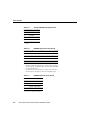
Rear-Panel Connectors
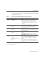
Figure 1-2 through Figure 1-6 illustrate the connectors for each of the five router models.
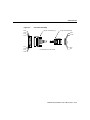
Figure 1-2
Cisco 1601 Rear Panel
DO NOT INSTALL ANY WAN
MODULE WITH POWER ON
ETHERNET Ø
AUI
CONSOLE
RDY
LNK
Figure 1-3
SERIAL Ø
WIC
OK
FLASH PC CARD
14 VDC
H7183
10 BASE T
Cisco 1602 Rear Panel
DO NOT INSTALL ANY WAN
MODULE WITH POWER ON
LNK
1-4
ETHERNET Ø
AUI
SERIAL Ø 56K DSU/CSU
CONSOLE
CARRIER
ALARM
LOOPBACK
Cisco 1600 Series Router Hardware Installation Guide
WIC
OK
FLASH PC CARD
14 VDC
H7184
10 BASE T
Rear-Panel Connectors
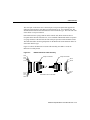
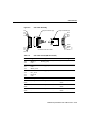
Figure 1-4
Cisco 1603 Rear Panel
DO NOT INSTALL ANY WAN
MODULE WITH POWER ON
AUI
LNK
Figure 1-5
CONSOLE
ISDN BRI Ø S/T
WIC
OK
OK
FLASH PC CARD
14 VDC
H7185
ETHERNET Ø
10 BASE T
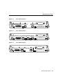
Cisco 1604 Rear Panel
DO NOT INSTALL ANY WAN
MODULE WITH POWER ON
AUI
ISDN BRI Ø U
ISDN PHONE
NT 1
OK
LNK
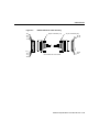
Figure 1-6
CONSOLE
WIC
OK
FLASH PC CARD
14 VDC
H7186
ETHERNET Ø
10 BASE T
Cisco 1605 Rear Panel
DO NOT INSTALL ANY WAN
MODULE WITH POWER ON
LNK
ETHERNET Ø
AUI
ETHERNET 1 10 BASE T
LNK
CONSOLE
WIC
OK OK
FLASH PC CARD
14 VDC
H10374
10 BASE T
Overview of the Router 1-5
Rear-Panel Connectors
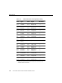
Table 1-2 describes the connectors on the rear panel of the router.
Table 1-2
Function—Rear Panel Connectors and Slots
Label
Router
Model
ETHERNET Ø
All
Function
• 10BASE T
• Connects the router to a 10BaseT Ethernet LAN through an
Ethernet hub or switch.
• AUI
• Connects the router to an Ethernet LAN through a transceiver.
CONSOLE
All
Connects the router to a terminal or to a PC running terminal
emulation software for configuration.
WIC
All
Slot for a WAN interface card, which provides an additional WAN
connection for models Cisco 1601 through Cisco 1604 and the only
WAN connection for the Cisco 1602.
FLASH PC CARD
All
Slot for the Flash PC card. The router is shipped to the customer
with the card already installed.
SERIAL Ø
Cisco 1601
Connects the router to serial WAN services, such as leased lines,
Frame Relay, 56-kbps services, SMDS, and X.25.
SERIAL Ø 56K DSU/CSU
Cisco 1602
Connects the router to 56-kbps and dataphone digital service (DDS)
through an integrated 56-kbps DSU/CSU.
ISDN BRI Ø S/T
Cisco 1603
Connects the router to ISDN services through an external NT1
device (purchased separately from the router).
ISDN BRI Ø U
Cisco 1604
Connects the router to ISDN services through an integrated NT1.
ISDN PHONE
Cisco 1604
Connects an ISDN device, such as an ISDN telephone, through the
router to the same ISDN line that the router uses.
ETHERNET 1 10BASE T
Cisco 1605
Connects the router to a 10BaseT Ethernet LAN through an
Ethernet hub or switch. The Cisco 1605 supports up to two Ethernet
LAN connections.
1-6
Cisco 1600 Series Router Hardware Installation Guide
Router Memory
Router Memory
The Cisco 1600 series routers are either of run-from-flash (RFF) or run-from-RAM (RFR)
models. Router model names with an R are RFR routers; all other models are RFF. In this
document, model names without an R refer to both RFF and RFR models, except where
noted. This section describes the two memory architectures used in the Cisco 1600 series
routers.
Run-From-Flash Architecture
With RFF, the microprocessor uses the uncompressed Cisco IOS software image that is
stored in Flash memory. The software image runs directly from Flash memory. RAM stores
working data such as Cisco IOS data structures, network routing tables, and packets to be
transmitted to and received from network interfaces.
The running software image cannot be used to download new software to Flash memory
because it would attempt to overwrite itself. (However, when you are using Dual Flash
Bank memory, you can download the new software image into a different Flash memory
partition.)
To download a new software image without using Dual Flash Bank memory, a boot-helper
image (called XBOOT) has been added to the ROM on the RFF models. The boot-helper
image is a small subset of Cisco IOS software that supports only a subset of the interfaces
and the WAN protocols. RFF ROM supports the following WAN interfaces. (These are all
onboard interfaces, not WAN-interface-card interfaces.)
•
•
•
•
Serial (synchronous and asynchronous) (Cisco 1601)
DSU/CSU (Cisco 1602)
ISDN S/T (Cisco 1603)
ISDN U (Cisco 1604 and Cisco 1604 R)
When upgrading the Cisco IOS software in Flash memory, you must boot the router from
the ROM image. The Flash memory can be overwritten because the Cisco IOS software
that is stored in Flash memory is not being used to run the router.
Overview of the Router 1-7
Router Memory
Run-From-RAM Architecture
With RFR, the Cisco IOS image is stored in Flash memory (usually in compressed form),
but is loaded into RAM before being used to operate the router. The running software image
then resides in RAM, so a new software image can be downloaded and copied over the
software image stored in Flash memory.
In RFR routers, only a minimal boot-helper image is stored in the ROM for disaster
recovery. Initial loading of a software image into Flash memory is done over the console
port or the local Ethernet.
Because the Cisco IOS image is stored in compressed form in Flash memory and then
decompressed when loaded into RAM, the standard configuration for the RFR models
contains less Flash memory but more DRAM than the RFF models.
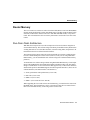
Table 1-3 is a summary comparison of these two memory architectures.
Table 1-3
Memory Architecture Comparison
Feature
Run-From-Flash Routers
Run-From-RAM Routers
Cisco IOS software
online download
Yes, when using Dual Flash Bank memory
Yes
Flash memory use
• Stores uncompressed Cisco IOS
software image.
• Stores compressed Cisco IOS software
image.
• The Flash PC card cannot be removed
when the router is operating.
• The Flash PC card can be removed after
the router has finished booting up and
has passed the power-on self-test.
• Packet memory
• Packet memory
• Routing tables
• Routing tables
• Dynamic memory used by Cisco IOS
software
• Dynamic memory used by Cisco IOS
software
RAM use
• Running uncompressed Cisco IOS
software image
DRAM capacity
1-8
• Standard: 2 MB onboard
• Standard: 8 MB onboard
• Maximum: 18 MB (with 16-MB
SIMM)
• Maximum: 24 MB (with 16-MB
SIMM)
Cisco 1600 Series Router Hardware Installation Guide
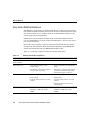
Run-From-RAM Architecture
Table 1-3
Memory Architecture Comparison (Continued)
Feature
Run-From-Flash Routers
Run-From-RAM Routers
Flash PC card capacity
• Standard: 4 MB
• Standard: 2 MB
• Maximum: 12 MB
• Maximum: 12 MB
• Cisco IOS software image can be
downloaded over any interface and with
any WAN protocol supported by the
ROM boot helper.
• Cisco IOS software image can be
downloaded with the ROM boot helper
over the Ethernet 0 interface.
Disaster recovery
(Router fails and the image
store in Flash memory is
corrupted).
• Cisco IOS software image can be
downloaded over the console port by
using the xmodem or ymodem
commands.
• Flash PC card can upgraded by booting
from a Cisco IOS software image stored
in another Flash memory bank (if using
Dual Flash Bank memory).
• Cisco IOS software image can be
downloaded over the console port by
using the xmodem or ymodem
commands.
• Flash PC card can upgraded by booting
from a Cisco IOS software image stored
in another Flash memory bank (if using
Dual Flash Bank memory).
Overview of the Router 1-9
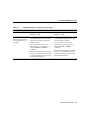
Router Memory
Identifying the Memory Architecture from Cisco IOS
Use the Cisco IOS show version command to display some memory architecture
information for your router (show in boldface in the example output):
•
•
•
Amount of onboard DRAM (a type of RAM)
Whether the Cisco IOS software is running from RAM or Flash memory
Amount of Flash memory
Router# show version
Cisco Internetwork Operating System Software
IOS (tm) 1600 Software (C1600-BNSY-M), EARLY DEPLOYMENT RELEASE SOFTWARE
11.2(9)P
Copyright (c) 1986-1997 by cisco Systems, Inc.
Compiled Mon 11-Aug-97 14:10 by cisco
Image text-base: 0x02005000, data-base: 0x02477BD0
ROM: System Bootstrap, Version 11.1(12)AA,DEPLOYMENT RELEASE SOFTWARE
(f)
ROM: 1600 Software (C1600-RBOOT-R), Version 11.1(12)AA, EARLY DEPLOYMENT
RELEASE
Router uptime is 12 minutes
System restarted by power-on
System image file is "flash:c1600-bnsy-mz", booted via flash
cisco 1605 (68360) processor (revision C) with 7680K/512K bytes of
memory.
Processor board ID 06027889, with hardware revision 00000000
Bridging software.
X.25 software, Version 2.0, NET2, BFE and GOSIP compliant.
2 Ethernet/IEEE 802.3 interface(s)
System/IO memory with parity disabled
8192K bytes of DRAM onboard
System running from RAM
8K bytes of non-volatile configuration memory.
4096K bytes of processor board PCMCIA flash (Read/Write)
Configuration register is 0x2102
1-10
Cisco 1600 Series Router Hardware Installation Guide
Unpacking the Router
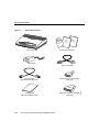
Unpacking the Router
Figure 1-7 shows the other items that come with your router. All of these are in the
accessory kit that is inside the box that your router came in.
Overview of the Router 1-11
Unpacking the Router
Figure 1-7
Router Box Contents
ion
tat
en
cum OM
Do D-R
C
Cisco 1600 router
Hardw
a
Install re
ation
Guide
Softw
Confi are
gurati
o
Guide n
Product documentation
Power supply
1-12
Console cable
(light blue, RJ-45-to-RJ-45)
DB-9-to-RJ-45 console adapter
(light gray)
Flash PC card
(Already installed in router)
DB-25-to-RJ-45 console adapter
(light gray)
Cisco 1600 Series Router Hardware Installation Guide
H10382
Power cord (black)
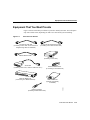
Equipment That You Must Provide
Equipment That You Must Provide
Figure 1-8 shows items that you will have to provide to install your router. You will require
only some of these items, depending on what Cisco 1600 model you are installing.
Figure 1-8
Items That You Provide
RJ-48S-to-RJ-48S cable
(If installing a Cisco 1602. An RJ-45-to-RJ-45
straight-through cable can substitute.)
RJ-45-to-RJ-45 straight-through cable
(If installing a Cisco 1603 or Cisco 1604)
10BaseT Ethernet cable
NT1 device
(If installing a Cisco 1603)
Serial cable
(If installing a Cisco 1601, order this cable from Cisco.)
Ethernet AUI transceiver
(If connecting to an AUI Ethernet)
AUI
7
6
5
4
3
2
1
Ethernet 10BaseT hub
(If connecting to a 10BaseT Ethernet)
Phillips screwdriver
(If installing a WAN interface card)
WAN interface card
(Optional, might already
be installed)
H10383
8
Overview of the Router 1-13
Equipment That You Must Provide
1-14
Cisco 1600 Series Router Hardware Installation Guide
C H A PT E R
2
Installing the Router
This chapter contains hardware installation procedures for Cisco 1600 series routers and
includes the following sections:
•
•
•
•
•
Before Installing
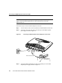
Connecting Power and Turning On the Router
Connecting the Router to the LAN
Connecting the Router to the WAN
Connecting the Console Port
Note You might want to perform some optional installation steps that are not explained in
this chapter, including wall-mounting the router, installing the Flash PC card, connecting
an ISDN telephone, or installing a WAN interface card. These procedures are explained in
the “Optional Installations” chapter later in this document.
Before Installing
Cisco 1600 series routers are shipped to you ready for desktop mounting. Before making
the power and network connections, simply set the router on a desktop, shelf, or other flat
surface. Be sure to read the safety information in the Regulatory Compliance and Safety
Information for Cisco 1600 and Cisco 1700 Routers that came with your router.
Warning Read the installation instructions before you connect the system to its
power source.
Installing the Router 2-1
Connecting Power and Turning On the Router
Caution Do not place anything on top of the router that weighs more than
10 pounds (4.5 kg). Excessive weight on top of the router could damage the
chassis.
Warning Do not work on the system or connect or disconnect cables during
periods of lightning activity.
Connecting Power and Turning On the Router
If you turn on the router before making network connections, you can verify your
installation by checking the appropriate LEDs during the installation process.
Warning The power supply is designed to work with TN power systems.
Warning This product relies on the building’s installation for short-circuit
(overcurrent) protection. Ensure that a fuse or circuit breaker no larger than
120 VAC, 15A U.S. (240 VAC, 10A international) is used on the phase conductors
(all current-carrying conductors).
Warning This equipment is intended to be grounded. Ensure that the host is
connected to earth ground during normal use.
Follow these steps to connect the router to power and turn it on:
2-2
Step 1
Connect the DC power cable (included with the router) from the power supply
to the DC power input on the rear panel of the router.
Step 2
Connect the male end of the power cable to the power outlet.
Step 3
Connect the female end of the cable to the male receptacle on the power supply.
Step 4
On the rear panel of the router, turn ON the power by setting the switch labeled
| / O to the | position.
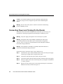
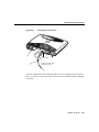
Step 5
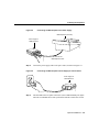
Slip the wire clip over the power cord to ensure that the power cord remains
attached to the router, as shown in Figure 2-1.
Cisco 1600 Series Router Hardware Installation Guide
Connecting Power and Turning On the Router
Check the following LEDs:
•
The SYSTEM PWR LED (front panel)—On when power is being supplied
to router.
•
The SYSTEM OK LED (front panel)—On when router software is
operational. (This LED first blinks and then remains on continuously.)
•
The OK LED (rear panel, next to Flash PC card slot)—On when the Flash
memory card is correctly installed.
Figure 2-1
Power Cord Clip Attachment
H10962
Step 6
Power cord
Clip
Installing the Router 2-3
Connecting the Router to the LAN
Connecting the Router to the LAN
The router can be connected to two 10BaseT or AUI Ethernet LANs.
Warning Do not work on the system or connect or disconnect cables during
periods of lightning activity.
Warning The ports labeled 10BASET, CONSOLE, and FLASH PC CARD are
safety extra-low voltage (SELV) circuits. SELV circuits should only be connected
to other SELV circuits. Because the BRI circuits are treated like
telephone-network voltage, avoid connecting the SELV circuit to the telephone
network voltage (TNV) circuits.
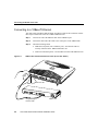
Connecting to an AUI Ethernet
You must supply an Ethernet transceiver for this connection. Follow these steps to connect
the router to an AUI Ethernet LAN:
Note Some transceivers connect directly to the router AUI port. If you have this type of
transceiver, you do not need the AUI adapter cable. You can connect the transceiver to the
AUI port on the router and then go to Step 3.
2-4
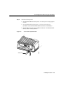
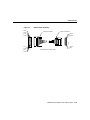
Step 1
Connect the one end of the AUI adapter cable to the transceiver.
Step 2
Connect the other end of the AUI adapter cable to the AUI port on the router
(Figure 2-2).
Step 3
Connect the transceiver to the Ethernet LAN by using a BNC connector
(Figure 2-2).
Cisco 1600 Series Router Hardware Installation Guide
Connecting to an AUI Ethernet
Step 4
•
The transceiver power LED (the location depends on model)—On when
power is supplied to the transceiver through the router.
•
The LAN ACT LED (front panel)—Blinks when there is traffic on the
Ethernet LAN.
AUI Port to Ethernet Transceiver Connection (Cisco 1601 Shown)
H7197
Figure 2-2
Check the following LEDs:
DO NO
T
MODU INSTAL
LE WIT L ANY
WA
H PO
WER N
ON
Transceiver
adapter cable
Ethernet AUI port
(DB-15)
(with jackscrews
or slide-latch)
Router
Ethernet
transceiver
BNC connector
To thin
Ethernet
network
To thin
Ethernet
network
Installing the Router 2-5
Connecting the Router to the LAN
Connecting to a 10BaseT Ethernet
You must supply an Ethernet hub and an RJ-45-to-RJ-45 cable for this connection. Follow
these steps to connect the router to a 10BaseT Ethernet LAN:
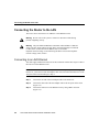
Figure 2-3
Step 1
Connect one end of the Ethernet cable to the 10BASE T port.
Step 2
Connect the other end of the cable to one of the ports on the 10BaseT hub.
Step 3
Check the following LEDs:
•
LNK LED (rear panel, next to 10BaseT port)—On when the router is
correctly connected to the 10BaseT Ethernet LAN.
•
LAN ACT LED (front panel)—On when there is traffic on the Ethernet LAN.
10BaseT Port to Ethernet Hub Connection (Cisco 1601 Shown)
LN K
WI C
OK OK
DO NO
T
MODU INSTALL
LE WIT
AN
H PO Y WAN
WER
ON
10BaseT link LED
10BaseT port
AUI
8
7
H7198
1
Straight-through
Ethernet cable
2-6
10BaseT hub
Cisco 1600 Series Router Hardware Installation Guide
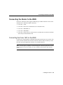
Cisco 1605 LAN Connections
Cisco 1605 LAN Connections
Unlike the other Cisco 1600 models, the Cisco 1605 can support two LAN connections
(Figure 2-4).
The Cisco 1605 has two Ethernet Ø ports. However, you can use only one of the Ethernet Ø
ports at any one time. A second Ethernet connection must always be on the
ETHERNET 1 10BASE T port. The Ethernet ports can be used in one of these two
combinations:
ETHERNET Ø 10BASE T and ETHERNET 1 10BASE T
ETHERNET Ø AUI and ETHERNET 1 10BASE T
Make the LAN connections for the Cisco 1605 as you would any of the other models.
Installing the Router 2-7
Connecting the Router to the LAN
Figure 2-4
Cisco 1605 with Two Ethernet LAN Connections
Ethernet AUI port
(DB-15)
(with jackscrews
or slide-latch)
LNK
OK
WIC
DO NOT
MOD
INST
ALL
ULE
WITH ANY
POW WAN
ER ON
OK OK
Router
Ethernet
transceiver
10BaseT hub
BNC connector
AUI
8
To thin
Ethernet
network
7
6
5
Straight-through
Ethernet cable
2-8
4
3
2
1
H10603
To thin
Ethernet
network
Cisco 1600 Series Router Hardware Installation Guide
Connecting the Router to the WAN
Connecting the Router to the WAN
Each Cisco 1600 series router supports a different type of WAN connection. This section
describes how to make these WAN connections:
•
•
•
•
•
Cisco 1601—Serial
Cisco 1602—Data service unit/channel service unit (DSU/CSU)
Cisco 1603—ISDN BRI S/T
Cisco 1604—ISDN BRI U
Cisco 1605—Refer to the Cisco WAN Interface Cards Hardware Installation Guide that
came with your WAN interface card.
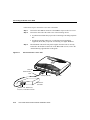
Connecting the Cisco 1601 to the WAN
For this step, you must purchase a shielded serial transition cable from Cisco Systems. The
router end of the shielded serial transition cable has a DB-60 connector. When you order
the cable, specify the appropriate connector for your WAN interface.
Note To ensure agency compliance with electromagnetic emissions requirements, such as
electromagnetic interference (EMI), use only a shielded serial transition cable with the
router.
Installing the Router 2-9
Connecting the Router to the WAN
Follow these steps to connect the Cisco 1601 to the WAN:
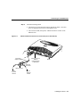
Step 1
Connect the cable DB-60 connector to the SERIAL Ø port on the Cisco 1601.
Step 2
Connect the other end of the cable to one of the following devices:
Step 3
Asynchronous modem that you provide if connecting to an analog telephone
line.
•
Synchronous modem, DSU/CSU, or other data circuit-terminating
equipment (DCE) that you provide if connecting to a digital WAN line.
Check the RDY LED on the rear panel. It lights when the router is correctly
connected to the modem or DSU/CSU. If the RDY LED is not on, refer to the
“Troubleshooting” appendix later in this guide.
Serial Connection—Cisco 1601
H7199
Figure 2-5
•
LNK
RDY LED
LNK
WIC
OK OK
DO NOT
MODUL INSTAL
E WIT L ANY WA
H POW
N
ER ON
Serial transition
cable
Serial port (DB-60)
DSU/CSU or
other DCE
EIA/TIA-232, EIA/TIA-449,
V.35, X.21, or EIA-530 connector
2-10
Cisco 1600 Series Router Hardware Installation Guide
Router
Connecting the Cisco 1602 to the WAN
Connecting the Cisco 1602 to the WAN
You must provide either an RJ-48S-to-RJ-48S or an RJ-45-to-RJ-45 cable for this step.
Follow these steps to connect the Cisco 1602 to the WAN:
Step 1
Connect one end of the cable to the router SERIAL Ø 56K DSU/CSU port.
Step 2
Connect the other end of the cable to the 56-kbps wall jack (Figure 2-6).
56-kbps Service Connection—Cisco 1602
H7200
Figure 2-6
LN K
LN K
W IC
OK OK
56-kbps
DSU/CSU
port
CARRIER
LED
RJ-48S-to-RJ-48S cable
Step 3
56-kbps wall jack
Check the CARRIER LED on the rear panel. It lights when the cable is correctly
connected and the router has synchronized with the central office switch.
Installing the Router 2-11
Connecting the Router to the WAN
Connecting the Cisco 1603 to the WAN
You must provide a Network Termination 1 (NT1) device and a straight-through
RJ-45-to-RJ-45 cable for this connection.
Warning Network hazardous voltages are present in the BRI cable. If you detach
the BRI cable, detach the end away from the router first to avoid possible electric
shock. Network hazardous voltages also are present on the system card in the area
of the BRI port (RJ-45 connector), regardless of when power is turned off.
Depending on where the Cisco 1603 is being used, the ISDN BRI connection can be
different. Follow these steps to connect the Cisco 1603 to the WAN:
2-12
Step 1
Use an RJ-45-to-RJ-45 cable to connect the cable to the ISDN Ø S/T port on the
router.
Step 2
Do one of these steps:
•
In North America—Connect the other end of the cable to the NT1
(Figure 2-7), and then connect the NT1 to the ISDN wall jack (Figure 2-8).
•
Outside North America—Connect the other end of the cable directly to the
ISDN wall jack (Figure 2-8).
Cisco 1600 Series Router Hardware Installation Guide
Connecting the Cisco 1603 to the WAN
Figure 2-7
NT1 Connection—Cisco 1603
LN K
LN K
WI C
OK OK
ISDN S/T port
Router
H7201
ISDN link
OK LED
Straight-through
RJ-45-to-RJ-45 cable
NT1 device
S/T port
Installing the Router 2-13
Connecting the Router to the WAN
ISDN Wall Jack Connection—Cisco 1603
H3587
Figure 2-8
Wall jack
Straight-through
BRI cable
Warning Network hazardous voltages are present in the BRI cable. If you detach
the BRI cable, detach the end away from the router first to avoid possible electric
shock. Network hazardous voltages also are present on the system card in the area
of the BRI port (RJ-45 connector), regardless of when power is turned off.
Step 3
2-14
Check the following LEDs:
•
The OK LED on the rear panel (next to ISDN S/T port) lights when the router
has synchronized with the central office switch.
•
The external NT1 might have an LED indicating synchronization with the
central office switch or other NT1 status. Check the NT1 documentation.
Cisco 1600 Series Router Hardware Installation Guide
Connecting the Cisco 1604 to the WAN
Connecting the Cisco 1604 to the WAN
You must provide a straight-through cable, either RJ-11-to-RJ-11 or RJ-45-to-RJ-45, for
this connection. Follow these steps to connect the Cisco 1604 to the WAN:
Step 1
Connect one end of the cable to the ISDN Ø U port on the router.
Step 2
Connect the other end of the cable directly to the ISDN BRI wall jack
(Figure 2-9).
Figure 2-9
ISDN BRI Connection—Cisco 1604
LN K
LN K
LN K
WI C
LN K
OK OK
Router
RJ-45-to-RJ-45 cable
ISDN BRI
wall jack
Step 3
H7202
NT1 LED
ISDN U port
The NT1 LED on the rear panel lights when the router has synchronized with
the central office switch.
Installing the Router 2-15
Connecting the Console Port
Connecting the Cisco 1605 to the WAN
The procedure for connecting the Cisco 1605 to the WAN depends on the type of WAN
interface card that is installed in the router. For instructions for the card that you are using,
refer to the Cisco WAN Interface Cards Hardware Installation Guide that came with your
WAN interface card.
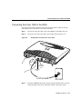
Connecting the Console Port
The cable and adapters required for this connection are included with the router. Follow
these steps to connect the router to a terminal or PC:
Step 1
Connect the light-blue console cable to the light-blue CONSOLE port on the
router (Figure 2-10).
Step 2
Use the correct adapter to connect the other end of the cable to your terminal or
PC.
Note If your terminal or PC has a console port that does not fit one of the adapters, you
must provide the correct adapter for that port.
2-16
Cisco 1600 Series Router Hardware Installation Guide
Connecting the Console Port
Connecting to Console Port
H7203
Figure 2-10
LN K
LN K
LN K
WI C
LN K
OK OK
Console port
Rollover console cable
(RJ-45-to-RJ-45)
You have completed the router installation and are ready to configure the router. Refer to
the Cisco 1600 Series Software Installation Guide for more information about configuring
your router.
Installing the Router 2-17
Connecting the Console Port
2-18
Cisco 1600 Series Router Hardware Installation Guide
C H A PT E R
3
Optional Installations
This chapter describes some procedures that you might not need for your router:
•
•
•
•
Installing the WAN Interface Card in the Router
Installing a Flash PC Card
Connecting an ISDN Telephone to the Cisco 1604
Wall-Mounting the Router
Installing a WAN Interface Card
Cisco 1600 series routers can support an additional WAN port on a one-port WAN interface
card that is installed in the router. This chapter describes the supported WAN interface cards
and describes the general procedure for installing any WAN interface card in any
Cisco 1600 series router.
For information about installing and connecting a specific card, refer to the Cisco WAN
Interface Cards Hardware Installation Guide that came with the card.
This procedure describes how to install a WAN interface card in a Cisco 1600 series router.
This example use an ISDN BRI U card and a Cisco 1601 router. The same procedure is
used to install any of the Cisco 1600-compatible cards in any Cisco 1600 series router.
Optional Installations 3-1
Installing a WAN Interface Card
Safety Information
This section lists safety warnings that you should be aware of before installing a WAN
interface card in the router.
Warning Only trained and qualified personnel should be allowed to install or
replace this equipment. (To see translated versions of this warning, refer to the
document that accompanied the router.)
Warning Before working on equipment that is connected to power lines, remove
jewelry (including rings, necklaces, and watches). Metal objects will heat up when
connected to power and ground and can cause serious burns or weld the metal
object to the terminals. (To see translated versions of this warning, refer to the
document that accompanied the router.)
Warning Before opening the chassis, disconnect the telephone-network cables
(from the card) to avoid contact with telephone-network voltages. (To see
translated versions of this warning, refer to the document that accompanied the
router.)
Warning Do not work on the system or connect or disconnect cables during
periods of lightning activity. (To see translated versions of this warning, refer to
the document that accompanied the router.)
3-2
Cisco 1600 Series Router Hardware Installation Guide
Installing the WAN Interface Card in the Router
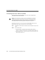
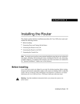
Installing the WAN Interface Card in the Router
Follow these steps to install the card in a Cisco 1600 series router:
Turn the router OFF, and disconnect the cable from the socket labeled 14 VDC
on the rear panel of the router.
Step 2
Loosen the captive screws on the WAN interface card-slot cover on the rear
panel of the router (Figure 3-1).
Removing the Slot Cover (Cisco 1601 Shown)
H7179
Figure 3-1
Step 1
DO NO
MODU T INSTAL
L
LE W
ITH POANY WAN
WER
ON
WAN interface card slot cover
Step 3
Remove the metal plate that covers the WAN interface card slot.
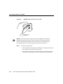
Step 4
Hold the WAN interface card by the front panel, and line up the edges of the card
with the guides (Figure 3-2).
Optional Installations 3-3
Installing a WAN Interface Card
Caution Do not connect a WAN cable to the card until you have completed the
installation procedure.
Installing the WAN Interface Card in the Router (Cisco 1601 and BRI U Card Shown)
H7180
Figure 3-2
LN K
W IC
OK O
K
Guides
Guides
WAN interface card
3-4
Step 5
Insert the card in the slot and gently push it in until the front panel of the card is
flush with the rear panel of the router.
Step 6
Tighten the card captive screws.
Cisco 1600 Series Router Hardware Installation Guide
Installing a Flash PC Card
For more information about the card that you are using, refer to the Cisco WAN Interface
Cards Hardware Installation Guide that came with the card.
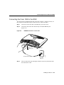
Installing a Flash PC Card
This section explains how to install the Flash PC card. The Flash PC card is a writable card
used to download new software to the router over the WAN.
Note Although the router is shipped from Cisco with the Flash PC card already installed,
you might have to install it if someone has removed the card for any reason. For example,
to configure your router, the system administrator might remove the card, add a
configuration file to it, and then return it to you.
Follow these steps to install the Flash PC card:
Step 1
Turn the router OFF.
Step 2
Insert the connector end of the card in the router slot, aligning the card edges
along the card-slot guides.
Step 3
Push the Flash PC card into the slot (Figure 3-3) until the card is seated.
When the card is completely seated in the connector, the blue button left of the Flash PC
card slot (Figure 3-3) pops out. If the blue button does not pop out, the card is not seated.
Press the blue button, remove the card, and reinsert it.
Caution Do not remove the Flash PC card from RFF router models while the
router is operating. The RFF models cannot operate without the Flash PC card.
Optional Installations 3-5
Installing a Flash PC Card
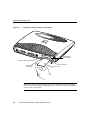
Installing a Flash PC Card (Cisco 1601 Shown)
H7178
Figure 3-3
LN K
W IC
OK O
K
WAN interface
card slot cover
Flash PC card OK LED
Flash PC card slot
Blue plastic
eject button
Flash PC card
Note After you have powered up the router, you can check that the card is functioning
correctly. Refer to the chapter “Installing the Router” earlier in this guide for information
on how to power up the router.
3-6
Cisco 1600 Series Router Hardware Installation Guide
Connecting an ISDN Telephone to the Cisco 1604
Connecting an ISDN Telephone to the Cisco 1604
This section describes how to connect an ISDN telephone (or another ISDN device) to the
ISDN PHONE port on the rear panel of the Cisco 1604. The ISDN PHONE port is only for
connecting a second ISDN device. Routing cannot be performed over this port.
Note The router does not supply power to a device connected to the ISDN PHONE port.
Any device connected to the ISDN PHONE port must have its own internal or external
power supply.
Configuration Changes
When you are connecting a second ISDN device to the ISDN line through the router, you
need to use subaddressing on the ISDN line.
For more information about using subaddressing, refer to the “ISDN BRI Line
Configuration Requirements” section in the “Configuring the ISDN Line” appendix.
Before Installing the Telephone
This procedure in this section assumes that you have already connected the router
ISDN Ø U port to the ISDN wall-jack as described in the “Connecting the Cisco 1604 to
the WAN” section in the “Installing the Router” chapter earlier in this guide.
Installing the Telephone
This example procedure describes how to connect an AT&T ISDN telephone
(model ISDN 8510T) and an AT&T external power supply (model MSP-1) that supplies
power to this telephone. Depending on the model of telephone and power supply that you
are installing, the procedure for connecting the telephone and power supply could differ
slightly from the one shown in this section.
Optional Installations 3-7
Connecting an ISDN Telephone to the Cisco 1604
Note If the ISDN telephone model you are using does not require an external power
supply, connect the ISDN telephone RJ-45-to-RJ-45 cable directly to the router
ISDN PHONE port.
Follow these steps to connect an ISDN telephone to the router:
Step 1
Connect an RJ-45-to-RJ-45 cable (included) to the ISDN PHONE on the router.
Step 2
Connect the other end of the cable to the LINE port on the ISDN telephone
power supply, as shown in Figure 3-4.
Figure 3-4
Connecting an ISDN Telephone Power Supply to a Cisco 1604
LN K
LN K
OK
WI C
OK OK
ISDN U
port
ISDN
PHONE
port
OK LED
Wall jack
PHONE OTH
ER
LINE
Power supply for
ISDN telephone
Step 3
3-8
H7204
RJ-45-to-RJ-45 cables
Connect the ISDN telephone RJ-45 cable to the PHONE port on the ISDN
telephone power supply, as shown in Figure 3-5.
Cisco 1600 Series Router Hardware Installation Guide
Installing the Telephone
Figure 3-5
Connecting an ISDN Telephone to a Power Supply
ISDN telephone (rear view)
H7131
Power supply for
ISDN telephone
ER
PHONE OTH
LINE
RJ-45-to-RJ-45
ISDN telephone cable
Step 4
Figure 3-6
Connect the power supply cable to the power outlet, as shown in Figure 3-6.
Connecting an ISDN Telephone Power Supply to a Power Outlet
H7130
Power supply for
ISDN telephone
Step 5
The OK LED on the rear panel of the router (next to ISDN PHONE port) lights
when the second ISDN device has synchronized with the central office switch.
Optional Installations 3-9
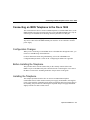
Wall-Mounting the Router
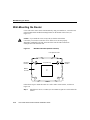
Wall-Mounting the Router
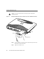
Cisco 1600 series routers can be wall-mounted by using two number-six, 3/4-inch screws
(not included) and the molded mounting brackets on the bottom of the router (see
Figure 3-7).
Caution If you install the screws in drywall, use hollow wall-anchors
(1/8 inch by 5/16 inch) to secure the screws. If the screws are not properly
anchored in wallboard or drywall, the strain of the network cable connections
could pull the router from the wall.
Figure 3-7
Wall-Mount Brackets (Bottom of Router)
Front panel of router
Mounting
bracket
Mounting
bracket
7.5" (19.05 cm)
H7235
Bottom
of router
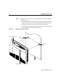
Follow these steps to mount the router on a wall or other vertical surface, as shown in
Figure 3-8:
Step 1
3-10
Install the two screws 7.5 inches (19.05 centimeters) apart on a wall or other flat
surface.
Cisco 1600 Series Router Hardware Installation Guide
Wall-Mounting the Router
Step 2
Figure 3-8
Hang the router on the screws by the mounting brackets so that the following
conditions are met:
•
The front panel LEDs face upward and are easily visible. You will use these
LEDs to verify that the router is operating properly. Mounting the router in
this position also reduces strain on the network cable connections.
•
The desktop power supply does not hang from its cable. If the power supply
is not supported, it will disconnect from its cable.
Mounting the Router on a Wall
Front panel of router
Wall-mount
screw
7.5
"(
19
.05
cm
)
H7236
Wall-mount
screw
Wall
Mounting brackets
Optional Installations 3-11
Wall-Mounting the Router
3-12
Cisco 1600 Series Router Hardware Installation Guide
A P PEN D I X
A
Troubleshooting
Use this information to help isolate problems you might encounter with Cisco 1600 series
routers or to rule out the router as the source of the problem.
This appendix contains the following sections:
•
•
•
•
Recovering a Lost Enable Password
Problem Solving
Front Panel LEDs
Rear Panel LEDs
For information about the Cisco 1600 series ROM monitor, refer to the “ROM Monitor”
appendix in the Cisco 1600 Series Software Configuration Guide that came with your
router.
If you cannot locate the source of the problem, contact your local reseller for advice. Before
you call, have the following information ready:
•
•
•
•
•
•
Chassis type and serial number
Maintenance agreement or warranty information
Type of software and version number
Date you received the chassis
Brief description of the problem
Brief explanation of the steps you have taken to isolate the problem
Troubleshooting A-1
Recovering a Lost Enable Password
Recovering a Lost Enable Password
This section describes how to recover a lost enable password.
Note You can recover a lost enable password, but not an enable secret password. This
password is encrypted and must be replaced with a new enable secret password. See the
“Hot Tips” section on Cisco Connection Online (CCO) for information on replacing enable
secret passwords.
Follow these steps to recover a lost enable password:
Step 1
Connect an ASCII terminal or a PC running a terminal-emulation program to the
CONSOLE port on the rear panel of the router. Refer to the section “Connecting
the Console Port” in the “Installing the Router” chapter.
Step 2
Configure the terminal to operate at 9600 baud, 8 data bits, no parity, and
1 stop bit.
Step 3
Reboot the router.
Step 4
At the user EXEC prompt (Router>), enter the show version command to
display the existing configuration register value:
Router> show version
Step 5
Record the setting of the configuration register. It is usually 0x2102 or 0x102.
Step 6
Record the break setting.
•
•
Break enabled—bit 8 is set to 0.
Break disabled (default setting)—bit 8 is set to 1.
Note To enable break, enter the config-register 0x01 EXEC command.
A-2
Cisco 1600 Series Router Hardware Installation Guide
Recovering a Lost Enable Password
Step 7
Do one of the following:
•
•
If break is enabled, go to Step 8.
If break is disabled, turn the router OFF, wait 5 seconds, and turn it ON again.
Within 60 seconds, press the Break key. The terminal displays the
ROM monitor prompt. Go to Step 9.
Note Some terminal keyboards have a key labeled Break. If your keyboard does not have
a Break key, refer to the documentation that came with the terminal for instructions on how
to send a break.
Step 8
Send a break. The terminal displays the following prompt:
rommon 2>
Step 9
Enter confreg 0x142 as follows to reset the configuration register:
rommon 2> confreg 0x142
Step 10
Initialize the router by entering the initialize command:
rommon 2> initialize
The router cycles its power, and the configuration register is set to 0x142. The
router uses the boot ROM system image, indicated by the system configuration
dialog:
--- System Configuration Dialog ---
Step 11
Enter no in response to the prompts until the following message is displayed:
Press RETURN to get started!
Step 12
Press Return. The following prompt appears:
Router>
Troubleshooting A-3
Recovering a Lost Enable Password
Step 13
Enter the enable command to enter enable mode. Configuration changes can be
made only in enable mode:
Router> enable
The prompt changes to the privileged EXEC prompt:
Router#
Step 14
Enter the show startup-config command to display the enable password in the
configuration file:
Router# show startup-config
Step 15
Enter the configure terminal command to enter configuration mode:
Router# configure terminal
Step 16
Enter the configure register command to reset the configuration register to the
original value that you recorded in Step 5.
Step 17
Press Ctrl-Z to exit configuration mode.
Note To return to the configuration being used before recovering the lost enable password,
do not save the configuration changes before rebooting the router.
Step 18
A-4
Reboot the router, and enter the recovered password.
Cisco 1600 Series Router Hardware Installation Guide
Problem Solving
Problem Solving
The key to problem solving is to isolate the problem to a specific subsystem by comparing
what the router is doing to what it should be doing.
When problem solving, consider the following subsystems of the router:
•
WAN interface cards—Refer to the LEDs on the cards and the LEDs on the router front
panel to help identify a failure. For information on the front panel LEDs, refer to the
“Front Panel LEDs” section later in this appendix.
•
•
Cables—Check all the external cables that connect the router to the network.
•
ISDN configuration—Consider ISDN-specific hardware and software configurations
(Cisco 1603, Cisco 1604, and ISDN BRI WAN interface cards only).
Power system—Consider the external power source, power cable, router power supply,
and circuit breaker. Check for inadequate ventilation or air circulation.
Troubleshooting WAN Interface Cards and Cables
Check for the following symptoms to help isolate the problem:
•
WAN interface card is not recognized by the router.
— Make sure that the card is correctly installed in the router. Refer to the “Installing a
WAN Interface Card” section in the “Optional Installations” chapter.
— Check the LEDs on the card and on the front panel of the router.
— If you are using a Cisco 1603 or Cisco 1604, check that the router does not have a
ISDN S/T or an ISDN U card installed.
•
WAN interface card is recognized, but interface ports do not initialize.
— Make sure that the card is correctly installed in the router. Refer to the “Installing a
WAN Interface Card” section in the “Optional Installations” chapter.
— Check the external cable connections to make sure they are secure.
•
Router does not boot properly or constantly or intermittently reboots.
— Make sure that the card is correctly installed in the router. Refer to the “Installing a
WAN Interface Card” section in the “Optional Installations” chapter.
Troubleshooting A-5
Problem Solving
— Make sure that the Flash PC card is correctly installed in the router. For more
information on installing the card, refer to the “Installing a Flash PC Card” section
in the “Optional Installations” chapter.
•
Router boots, but the console screen is frozen.
— Check the external console connection and make sure it is secure.
— Verify that the parameters for your terminal are set to the following:
9600 baud
8 data bits
No parity generated or checked
1 stop bit
•
Router powers on and boots only when a particular WAN interface card is removed from
the router.
— Replace the card. Consult your reseller or local Cisco sales office for warranty
information.
— If you are using a Cisco 1603 or Cisco 1604, check that the router does not have a
ISDN S/T or an ISDN U card installed.
•
Router powers on and boots only when a particular cable is disconnected.
— There might be a problem with the WAN interface card or card cables. Consult your
reseller or local Cisco sales office for warranty information.
A-6
Cisco 1600 Series Router Hardware Installation Guide
Troubleshooting the Power System
Troubleshooting the Power System
If the router external power supply fails, it should be returned to Cisco. Check the following
items to help isolate the problem:
•
Router shuts down after being on a short time.
— Check the environmental site requirements in the “Site Requirements” section in
the Regulatory Compliance and Safety Information for Cisco 1600 and Cisco 1700
Routers document that came with your router.
— If the front-panel SYSTEM PWR LED is not on, the power supply has failed.
•
•
If the router partially boots, but all LEDs remain off, the power supply has failed.
•
If the front-panel SYSTEM PWR LED is on, the front-panel SYSTEM OK LED is off,
and the router does not pass console or EIA data, the power supply has failed.
If the router is on, but the front-panel SYSTEM PWR LED is off, the power supply has
failed.
Troubleshooting ISDN
This section describes problems related to the ISDN line that might occur.
Two commands are useful when troubleshooting ISDN:
•
For routers with an ISDN S/T interface, enter the clear interface bri0 command to
terminate any active ISDN calls and to reset the ISDN BRI interface:
Router# clear interface bri0
•
For routers with an ISDN U interface, enter the clear controller bri0 command to
terminate any active ISDN calls, to reset the ISDN BRI interface, and to reset the ISDN
line between the router and the central office switch:
Router# clear controller bri0
Troubleshooting A-7
Troubleshooting ISDN
Figure A-1 lists troubleshooting methods for ISDN-specific problems that might occur.
Figure A-1
Troubleshooting ISDN
Symptom
Checks
Causes and Solutions
Router is on:
OK LED (next to ISDN S/T port) is off
(Cisco 1603 and ISDN S/T WAN interface card).
• Is the SYSTEM OK LED
on?
• Possible router hardware
problem.
• Are all ISDN cables
properly connected?
• Possible ISDN line
problem. Check with ISDN
service provider.
• Is the NT1 LED on?
• Possible NT1 problem.
• Is the SYSTEM OK LED
on?
• Possible router hardware
problem.
• Are all ISDN cables
properly connected?
• Possible ISDN line
problem. Check with ISDN
service provider.
• Is the ISDN line connected
to the router ISDN U port?
• Possible ISDN line
problem. Check with ISDN
service provider.
Router is on:
NT1 LED is off
(Cisco 1604 and ISDN U WAN interface card).
A-8
Cisco 1600 Series Router Hardware Installation Guide
Troubleshooting ISDN
Figure A-1
Troubleshooting ISDN (Continued)
Symptom
Checks
Causes and Solutions
NT1 LED is on.
• If there is no device
connected to the ISDN S/T
port, the OK LED should be
off.
• Possible router hardware
problem.
• Is the device connected to
the ISDN S/T port turned on
and correctly configured?
• Possible problem with
device connected to the
ISDN S/T port.
• Is the ISDN configured for
multipoint service?
• The service provider should
configure the line for
multipoint service.
• Is the external ISDN device
using both B channels?
• The service provider should
configure the line for
multipoint service.
• Does the device operate
correctly if the interface for
the Cisco 1604 ISDN U port
(interface bri0) is shut
down?
• The service provider should
configure the line for
multipoint service.
• Is the Cisco 1604 using both
B channels?
• The service provider should
configure the line for
multipoint service.
OK LED (next to ISDN S/T port) is off
(Cisco 1604).
Cisco 1604 cannot create an ISDN connection to
the remote router when an ISDN device is
connected to the ISDN S/T port.
ISDN device attached to the Cisco 1604 ISDN S/T
port does not operate correctly.
Troubleshooting A-9
Troubleshooting ISDN
Figure A-1
Troubleshooting ISDN (Continued)
Symptom
Checks
Cannot make an ISDN connection to remote
device (Cisco 1603, Cisco 1604, ISDN WAN
interface cards).
• Use show status command
to check the following:
— Does the current ISDN
switch type match actual
switch type being used?
Causes and Solutions
• Use the isdn switch-type
command to configure
correct switch type.
• Check the following:
A-10
— Is Layer 1 status
deactivated?
• Use the show controller
bri0 command to check for
the messages CO
RUNNING LOOPBACK
TESTS or CO TESTING. If
you receive these messages,
contact the service provider.
— If Layer 1 status is
active, does Layer 3
status say “2 Active
Layer 3 calls”?
• Router might have called
itself. Check destination
phone number configured
with the dialer map
command and the dialer
string command.
— If Layer 1 status is
active, does Layer 3
status say “No Active
Layer 3 call(s)”?
• Check destination phone
number. Check route to the
destination.
— If Layer 1 status is
active, does Layer 3
status say “1 Active
Layer 3 call”?
• Check router protocol
configurations.
Cisco 1600 Series Router Hardware Installation Guide
Front Panel LEDs
Front Panel LEDs
You can use the LEDs on the front panel of the router to determine router performance and
operation. This section contains information about reading the LEDs and using them to
troubleshoot problems.
Front Panel LEDs—Cisco 1601 and Cisco 1602
SER 0
SYSTEM
PWR
CD
WIC
CD/B1
LAN
ACT
OK
ACT
COL
H6863
Figure A-2
ACT/B2
Table A-1
Front Panel LED Functions—Cisco 1601 and Cisco 1602
LED
Color
Description
SYSTEM PWR
Green
The router is on, and DC power is being supplied.
SYSTEM OK
Green
The router has successfully booted. Blinks during the boot cycle.
LAN ACT
Green
Data is being sent to or received from the local Ethernet LAN.
LAN COL
Yellow
Flashing indicates packet collisions on the local Ethernet LAN.
SER 0 CD
Green
• Cisco 1601 has an active connection on the serial port.
• Cisco 1602 has an active connection on the DSU/CSU port.
SER 0 ACT
Green
• Cisco 1601 serial port is sending or receiving data.
• Cisco 1602 DSU/CSU port is sending or receiving data.
WIC CD/B1
Green
• Serial WAN interface card has an active connection on the serial port.
• ISDN WAN interface card has an ISDN connection on B-channel 1.
WIC ACT/B2
Green
• WAN interface card serial port is sending or receiving data.
• WAN interface card ISDN port has a connection on B-channel 2.
Troubleshooting A-11
Front Panel LEDs
Front Panel LEDs—Cisco 1603 and Cisco 1604
SYSTEM
PWR
BRI 0
WIC
B1
CD
ACT
OK
B2
Table A-2
LAN
COL
ACT
H7294
Figure A-3
Front Panel LED Functions—Cisco 1603 and Cisco 1604
LED
Color
Description
SYSTEM PWR
Green
The router is turned on, and DC power is being supplied.
SYSTEM OK
Green
The router has successfully booted. Blinks during the boot cycle.
LAN ACT
Green
Data is being sent to or received from the local Ethernet LAN.
LAN COL
Yellow
Flashing indicates packet collisions on the local Ethernet LAN.
BRI 0 B1
Green
An ISDN connection on B-channel 1.
Cisco 1604 only—If an ISDN device connected to the ISDN S/T port is using
B-channel 1, the LED turns on.
BRI 0 B2
Green
An ISDN connection on B-channel 2.
Cisco 1604 only—If an ISDN device connected to the ISDN S/T port is using
B-channel 2, the LED turns on.
WIC CD
Green
Active connection on the WAN interface card serial port.
WIC ACT
Green
Data is being sent over the WAN interface card serial port.
A-12
Cisco 1600 Series Router Hardware Installation Guide
Front Panel LEDs
Front Panel LEDs—Cisco 1605
SYSTEM
PWR
ETHØ
ETH1
ACT
ACT
CD/B1
OK
COL
Table A-3
WIC
ACT/B2
H10381
Figure A-4
COL
Front Panel LED Functions—Cisco 1605
LED
Color
Description
SYSTEM PWR
Green
The router is turned on, and DC power is being supplied.
SYSTEM OK
Green
The router has successfully booted. Blinks during the boot cycle.
ETHØ ACT
Green
Data is being sent to or received from the first Ethernet LAN.
ETHØ COL
Yellow
Flashing indicates packet collisions on the first Ethernet LAN.
ETH1 ACT
Green
Data is being sent to or received from the second Ethernet LAN.
ETH1 COL
Yellow
Flashing indicates packet collisions on the second Ethernet LAN.
WIC CD/B1
Green
Data is being sent to or received from the WAN interface card port.
WIC ACT/B2
Green
Data is being sent to or received from the WAN interface card port.
Troubleshooting A-13
Rear Panel LEDs
Rear Panel LEDs
Table A-4 describes the rear panel LEDs. For illustrations of these LEDs and the rear panel
of the routers, refer to Figure 1-2 through Figure 1-5 in the “Overview of the Router”
chapter.
Table A-4
Rear Panel LED Functions
LED
Color
Description
Green
Indicates 10BaseT link integrity. This LED is not on when
connected to an Ethernet network through the AUI port.
All Models
LNK
(next to ETHERNETØ 10BASET)
The Cisco 1605 has two LNK LEDs, one for each Ethernet
10BaseT port.
OK
(next to FLASH PC CARD slot)
Green
The Flash PC card is correctly installed.
Green
A serial port cable connection has been made to a modem or
DSU/CSU.
LOOPBACK
Yellow
The DSU/CSU is in DSU or CSU loopback mode.
ALARM
Yellow
An alarm condition exists on the DSU/CSU port.
CARRIER
Green
Indicates line synchronization or connection on the DSU/CSU
port.
Green
A physical connection has been established with the ISDN
central office switch.
Cisco 1601
RDY
Cisco 1602
Cisco 1603
OK
(next to ISDN BRIØ S/T port)
A-14
Cisco 1600 Series Router Hardware Installation Guide
Rear Panel LEDs
Table A-4
Rear Panel LED Functions (Continued)
LED
Color
Description
NT1
Green
A physical connection has been established from the router
internal NT1 to the ISDN central office switch.
OK (next to ISDN PHONE port)
Green
The device connected to the router ISDN S/T port has
established a physical connection with the ISDN central office
switch.
LNK
(next to ETHERNET1 10BASET)
Green
Indicates 10BaseT link integrity for the Ethernet 1 port.
OK
(next to WIC slot)
Green
The WAN interface card is correctly installed in the router.
Cisco 1604
Cisco 1605
Troubleshooting A-15
Rear Panel LEDs
A-16
Cisco 1600 Series Router Hardware Installation Guide
A P PEN D I X
B
Configuring the ISDN Line
This appendix describes how to order and configure an Integrated Services Digital Network
(ISDN) Basic Rate Interface (BRI) line for use with a Cisco 1600 series router with an
ISDN BRI interface or a Cisco 1600 series router with an ISDN BRI WAN interface card
installed.
This appendix contains the following sections:
•
•
•
•
•
ISDN BRI Line Configuration Requirements
ISDN BRI Switch Types
ISDN BRI Provisioning by Switch Type
Defining ISDN Service Profile Identifiers
ISDN Configuration Options
ISDN BRI Line Configuration Requirements
Before using a Cisco 1600 series router with an ISDN BRI interface or a Cisco 1600 series
router with an ISDN BRI WAN interface card installed, you must order a correctly
configured ISDN BRI line from your local telecommunications service provider.
This process varies significantly from provider to provider on a national and international
basis. However, following are some general guidelines:
•
•
Ask for two channels to be called by one number.
Ask for delivery of calling line identification. This is also known as Caller ID or
Automatic Number Identification (ANI).
Configuring the ISDN Line B-1
ISDN BRI Switch Types
•
If the router is going to be the only device attached to the ISDN BRI line, ask for
point-to-point service and a data-only line.
•
If you will be connecting another ISDN device (such as an ISDN telephone) to the
ISDN BRI line through the router, ask for point-to-multipoint service (subaddressing is
required) and a voice-and-data line.
ISDN BRI Switch Types
ISDN BRI supports a variety of service provider switches. Table B-1 lists, by geographic
areas, the ISDN switch types supported by the Cisco 1600 series routers ISDN BRI
interface. When configuring the router, use the isdn switch-type command followed by the
corresponding keyword.
Table B-1
ISDN BRI Switch Types
Switch Type
Keywords
Australia
Australian TS013 switches
basic-ts013
Europe
German 1TR6 ISDN switches
basic-1tr6
Norway NET3 switches (phase 1)
basic-nwnet3
NET3 ISDN switches (UK and others)
basic-net3
French VN2 ISDN switches
vn2
French VN3 ISDN switches
vn3
Japan
Japanese NTT ISDN switches
B-2
Cisco 1600 Series Router Hardware Installation Guide
ntt
ISDN BRI Provisioning by Switch Type
Table B-1
ISDN BRI Switch Types (Continued)
Switch Type
Keywords
North America
AT&T basic rate switches
basic-5ess
NT DMS-100 basic rate switches
basic-dms100
National ISDN-1 switches
basic-ni1
New Zealand
New Zealand Net3 switches
basic-nznet3
ISDN BRI Provisioning by Switch Type
The ISDN BRI line is configured (provisioned) for different types of services by the
ISDN BRI service provider. The person ordering the ISDN line must also order the
provisioning described in this section.
Table B-2 lists the provisioning that should be ordered for the router, based on the switch
type.
Table B-2
ISDN Provisioning by Switch Type
Switch Type
Provisioning
5ESS Custom BRI
For data only
Two B channels for data.
Point to point.
Terminal type = E.
One directory number (DN) assigned by service provider.
MTERM = 1.
Request delivery of calling line ID on Centrex lines.
Set speed for ISDN calls to 56 kbps outside local exchange.
Configuring the ISDN Line B-3
ISDN BRI Provisioning by Switch Type
Table B-2
ISDN Provisioning by Switch Type (Continued)
Switch Type
Provisioning
5ESS Custom BRI
For voice and data
(Use these values only if you have an ISDN telephone connected.)
Two B channels for voice or data.
Multipoint.
Terminal type = D.
Two directory numbers assigned by service provider.
Two service profile identifiers (SPIDs) required, assigned by service
provider.
MTERM = 2.
Number of call appearances = 1.
Display = No.
Ringing/idle call appearances = idle.
Autohold= no.
Onetouch = no.
Request delivery of calling line ID on Centrex lines.
Set speed for ISDN calls to 56 kbps outside local exchange.
Directory number 1 can hunt to directory number 2.
B-4
5ESS National ISDN
(NI-1) BRI
Terminal type = A.
Two B channels for voice and data.
Two directory numbers assigned by service provider.
Two SPIDs required; assigned by service provider.
Set speed for ISDN calls to 56 kbps outside local exchange.
Directory number 1 can hunt to directory number 2.
DMS-100 BRI
Two B channels for voice and data.
Two directory numbers assigned by service provider.
Two SPIDs required; assigned by service provider.
Functional signaling.
Dynamic terminal endpoint identifier (TEI) assignment.
Maximum number of keys = 64.
Release key = no, or key number = no.
Ringing indicator = no.
EKTS = no.
PVC = 2.
Request delivery of calling line ID on Centrex lines.
Set speed for ISDN calls to 56 kbps outside local exchange.
Directory number 1 can hunt to directory number 2.
Cisco 1600 Series Router Hardware Installation Guide
Defining ISDN Service Profile Identifiers
Defining ISDN Service Profile Identifiers
An ISDN service provider, usually a telephone company, can offer a variety of services.
Many providers use service profile identifiers (SPIDs) to identify the device that is using
the ISDN service, similar to the way that the telephone company uses a telephone number
to identify your standard telephone service. If you use a service provider that requires
SPIDs, the provider assigns your ISDN device one or more SPIDs when you first subscribe
to the service. Providers use different numbering schemes, but a SPID is usually a
seven-digit telephone number, plus some optional numbers. The provider also assigns your
device one or two local directory numbers (LDNs), which function as the router telephone
numbers. The LDN is the number that a remote router dials to make a call to the router.
Note SPIDs have significance only at the local-access ISDN interface. The remote router
is assigned a SPID when the ISDN BRI services are ordered for that router.
When your ISDN device accesses the switch to initialize the connection, first it must send
any assigned SPID(s) to the service provider. Otherwise, your ISDN device cannot place or
receive calls. Use the isdn spid command to define the SPID and the LDN on the router for
both ISDN BRI B channels, as follows:
Router(config-if)# isdn spid1 spid-number [ldn]
Router(config-if)# isdn spid2 spid-number [ldn]
Note Although the LDN is usually optional, it might be required so that the router answers
calls made to the second directory number.
Configuring the ISDN Line B-5
ISDN Configuration Options
ISDN Configuration Options
For information on how to configure Cisco 1600 series routers to dial into a central site
router over ISDN, refer to the Cisco 1600 Series Software Configuration Guide that came
with your router.
For more advanced information on configuring ISDN for Cisco 1600 series routers, refer to
the chapter “Configuring ISDN” in the Wide-Area Networking Configuration Guide
publication, which is on the Documentation CD-ROM that came with your router. This
document includes the information on the following topics:
•
•
•
•
•
•
•
•
•
•
•
Defining ISDN TEI Negotiation
Configuring Calling Line Identification (CLI) Screening
Configuring Called Party Number Verification
Configuring ISDN Calling Number Identification
Configuring the Line Speed for Calls Not ISDN End-To-End
Enabling PPP on VTY Lines
Configuring Encapsulation for Frame Relay or X.25 Networks
Configuring Network Addressing
Configuring Semipermanent Connections (optional, for Germany only)
Performing Configuration Self-Tests
Monitoring and Maintaining ISDN Interfaces
Snapshot Routing over ISDN
You can also configure snapshot routing for the router ISDN interface. Snapshot routing is
a method of learning remote routes dynamically and keeping the routes available for a
specified period of time, even though routing updates are not exchanged during that period.
See the chapter “Configuring DDR” in the Wide-Area Networking Configuration Guide
publication for detailed information about snapshot routing.
B-6
Cisco 1600 Series Router Hardware Installation Guide
Dial-on-Demand Routing Over ISDN
Dial-on-Demand Routing Over ISDN
To place calls on the ISDN interface, you must configure it with dial-on-demand routing
(DDR). See the chapter “Configuring DDR” in the Wide-Area Networking Configuration
Guide publication for detailed information about DDR.
Bandwidth on Demand and Dial Backup over ISDN
See the chapter “Configuring DDR” in the Wide-Area Networking Configuration Guide
publication for detailed information about bandwidth on demand and dial backup.
Configuring the ISDN Line B-7
ISDN Configuration Options
B-8
Cisco 1600 Series Router Hardware Installation Guide
A P PEN D I X
C
Hardware Specifications and
Cable Pinouts
This appendix contains the following sections:
•
•
Hardware Specifications—All models of Cisco 1600 series routers.
Cable Pinouts—Cables that can be used with Cisco 1600 series routers.
Hardware Specifications and Cable Pinouts C-1
Hardware Specifications
Hardware Specifications
Table C-1 lists the system specifications for Cisco 1600 series routers.
Table C-1
System Specifications
Description
Specification
Processor
Motorola MC68360 QUICC (33 MHz)
Dimensions
• Height
2.19 in. (5.56 cm)
• Width
11.15 in. (28.32 cm)
• Depth
8.67 in. (22.02 cm)
Weight
• Minimum (no WAN interface card installed)
1.65 LB (0.75 kg)
• Maximum
1.80 LB (0.82 kg)
Power (external)
14 VDC (+ / – 8%), minimum 1A
Console port
RJ-45 connector
10BaseT port
RJ-45 connector
AUI port
DB-15 connector
Flash memory slot
Flash PC card
Serial port (Cisco 1601)
DB-60 connector
DSU/CSU port (Cisco 1602)
RJ-48S connector
1
ISDN ports (Cisco 1603 and Cisco 1604)
RJ-45 connector
Temperature
• Operating
32 to 104°F (0 to 40°C)
• Nonoperating
-4 to 149°F (–20 to 65°C)
Operating humidity
5 to 95%, noncondensing
1
C-2
ISDN ports refer to the ISDN S/T and the ISDN U ports.
Cisco 1600 Series Router Hardware Installation Guide
Cable Pinouts
Cable Pinouts
This section includes the following pinouts:
•
•
•
•
•
•
•
•
•
•
•
10BaseT Port Pinouts
Straight-Through 10BaseT Cable (RJ-45 to RJ-45) Pinouts
Console Cable and Adapter Pinouts
56-kbps DSU/CSU (RJ-48S) Pinouts
ISDN BRI S/T Port Pinouts (RJ-45)
ISDN BRI U Port Pinouts (RJ-45)
EIA/TIA-232 DTE Cable Pinouts (DB-60 to DB-25)
EIA/TIA-449 DTE Cable Pinouts (DB-60 to DB-37)
X.21 DTE Cable Pinouts (DB-60 to DB-15)
V.35 Cable Pinouts (DB-60 to 34-Pin)
EIA-530 DTE Cable Pinouts (DB-60 to DB-25)
Table C-2
10BaseT Port Pinouts
8 Pin1
Description
1
TX+
2
TX–
3
RX+
6
RX–
1
Pins 4, 5, 7, and 8 are not used.
Hardware Specifications and Cable Pinouts C-3
Cable Pinouts
Table C-3
Straight-Through 10BaseT Cable (RJ-45 to RJ-45) Pinouts
RJ-45
Pin
Signal
Direction
RJ-45
Pin
1
TX+
—>
1
2
TX–
—>
2
3
RX+
<—
3
4
–
–
4
5
–
–
5
6
RX–
<—
6
7
–
–
7
8
–
–
8
The EIA/TIA-232 console port is configured as data terminal equipment (DTE) and uses
an RJ-45 connector. A console cable kit is provided with your router to connect a console
(an ASCII terminal or PC running terminal emulation software) to the console port. The
console cable kit contains an RJ-45-to-RJ-45 rollover cable and a RJ-45-to-DB-25 female
DTE adapter (labeled Terminal). Table C-4 lists the pinouts for the asynchronous serial
console port, the RJ-45-to-RJ-45 rollover cable, and the RJ-45-to-DB-25 female DTE
adapter.
C-4
Cisco 1600 Series Router Hardware Installation Guide
Cable Pinouts
Table C-4
Console Cable and Adapter Pinouts
Console
Port (DTE)
RJ-45-to-RJ-45
Roll-Over Cable
Signal
RJ-45 Pin
RJ-45 Pin
DB-9 Pin
DB-25 Pin
Signal
–
1
8
7
4
–
DTR
2
7
4
20
DSR
TxD
3
6
3
2
RxD
GND
4
5
5
7
GND
GND
5
4
5
7
GND
RxD
6
3
2
3
TxD
DSR
7
2
6
6
DTR
–
8
1
8
5
–
You can identify a rollover cable by comparing the two modular ends of the cable. (See
Figure C-1.) Holding the cables in your hand, side-by-side, with the tab at the back, the
wire connected to the pin on the outside of the left connector (pin 1) should be the same
color as the pin on the outside of the right connector (pin 8). On Cisco cables, pin 1 is white
on one connector, and pin 8 is white on the other connector.
Figure C-1
Identifying a Rollover Cable
Pin 1 on one connector and
pin 8 on the other connector
should be the same color.
Pin 8
H10632
Pin 1
Hardware Specifications and Cable Pinouts C-5
Cable Pinouts
Table C-5
56-kbps DSU/CSU (RJ-48S) Pinouts
8 Pin1
Description
1
Transmit
2
Transmit
7
Receive
8
Receive
1
Pins 3, 4, 5, and 6 are not
used.
Table C-6
8 Pin1
TE2
NT3
Polarity
3
Transmit
Receive
+
4
Receive
Transmit
+
5
Receive
Transmit
–
6
Transmit
Receive
–
1
2
3
Pins 1, 2, 7, and 8 are not used.
TE refers to terminal terminating layer 1 aspects of TE1, TA, and NT
functional groups. This applies to the Cisco 1603 and the ISDN BRI
S/T WAN interface card.
NT refers to network terminating layer 1 aspects of NT1 and NT2
functional groups. This applies to the Cisco 1604 ISDN S/T port.
Table C-7
C-6
ISDN BRI S/T Port Pinouts (RJ-45)
ISDN BRI U Port Pinouts (RJ-45)
8 Pin1
Function
3
No connection
4
Signal—Tip or Ring
5
Signal—Tip or Ring
6
No connection
1
Pins 1, 2, 7, and 8 are not used.
Cisco 1600 Series Router Hardware Installation Guide
Cable Pinouts
The serial port on the router uses a universal port, a 60-pin receptacle that supports the
following serial interfaces: EIA/TIA-232, EIA/TIA-449, X.21, V.35, and EIA-530. The
shielded serial transition cable determines the electrical interface type. The router end of all
of the cables is a 60-pin connector.
DTE connectors have a plug connector at the network end. (DCE connectors have a
receptacle at the network end.) However, V.35 is available in DTE mode either a receptacle
or a plug connector at the network end. The serial port operates in DTE and DCE modes.
The tables that follow list the signal pinouts for the DTE mode serial transition cables for
each router interface type.
Figure C-2 shows the EIA/TIA-232 serial cable assembly, and Table C-8 lists the
EIA/TIA-232 cable pinouts.
Figure C-2
60-pin connector
25-pin connector
J2-13
J2-25
H1972
1-46
1-45
1-16
1-15
EIA/TIA-232 Serial Cable Assembly
J1-1
1-30
1-31
1-60
J2-14
J2-1
Connectors are not to scale.
Hardware Specifications and Cable Pinouts C-7
Cable Pinouts
Table C-8
60 Pin1
Signal
Description
Direction
25 Pin
Signal
J1-50
J1-51
J1-52
MODE_0
GND
MODE_DCE
Shorting group
–
–
–
J1-46
Shield GND
Single
–
J2-1
Shield GND
J1-41
Shield
TxD/RxD
–
Twisted pair no. 5
—>
–
J2-2
Shield
TxD
–
J1-36
Shield
RxD/TxD
–
Twisted pair no. 9
<—
–
J2-3
Shield
RxD
–
J1-42
Shield
RTS/CTS
–
Twisted pair no. 4
—>
–
J2-4
Shield
RTS
–
J1-35
Shield
CTS/RTS
–
Twisted pair no. 10
<—
–
J2-5
Shield
CTS
–
J1-34
Shield
DSR/DTR
–
Twisted pair no. 11
<—
–
J2-6
Shield
DSR
–
J1-45
Shield
Circuit GND
–
Twisted pair no. 1
–
–
J2-7
Shield
Circuit GND
–
J1-33
Shield
DCD/LL
–
Twisted pair no. 12
<—
–
J2-8
Shield
DCD
–
J1-37
Shield
TxC/NIL
–
Twisted pair no. 8
<—
–
J2-15
Shield
TxC
–
J1-38
Shield
RxC/TxCE
–
Twisted pair no. 7
<—
–
J2-17
Shield
RxC
–
J1-44
Shield
LL/DCD
–
Twisted pair no. 2
—>
–
J2-18
Shield
LTST
–
J1-43
Shield
DTR/DSR
–
Twisted pair no. 3
—>
–
J2-20
Shield
DTR
–
J1-39
Shield
TxCE/TxC
–
Twisted pair no. 6
—>
–
J2-24
Shield
TxCE
–
1
C-8
EIA/TIA-232 DTE Cable Pinouts (DB-60 to DB-25)
Any pin not referenced is not connected.
Cisco 1600 Series Router Hardware Installation Guide
Cable Pinouts
Figure C-3
60-pin connector (J1)
37-pin connector (J2)
J2-19
J2-37
H1973
-46
-45
-16
-15
EIA/TIA-449 Serial Cable Assembly
J1-1
-30
-31
-60
Connectors are not to scale.
J2-20
J2-1
Hardware Specifications and Cable Pinouts C-9
Cable Pinouts
Table C-9
60 Pin1
Signal
Description
Direction
37 Pin
Signal
J1-49
J1-48
MODE_1
GND
Shorting group
–
–
–
J1-51
J1-52
GND
MODE_DCE
Shorting group
–
–
–
J1-46
Shield_GND
Single
_
J2-1
Shield GND
J1-11
J1-12
TxD/RxD+
TxD/RxD–
Twisted pair no. 6
—>
—>
J2-4
J2-22
SD+
SD–
J1-24
J1-23
TxC/RxC+
TxC/RxC–
Twisted pair no. 9
<—
<—
J2-5
J2-23
ST+
ST–
J1-28
J1-27
RxD/TxD+
RxD/TxD–
Twisted pair no. 11
<—
<—
J2-6
J2-24
RD+
RD–
J1-9
J1-10
RTS/CTS+
RTS/CTS–
Twisted pair no. 5
—>
—>
J2-7
J2-25
RS+
RS–
J1-26
J1-25
RxC/TxCE+
RxC/TxCE–
Twisted pair no. 10
<—
<—
J2-8
J2-26
RT+
RT–
J1-1
J1-2
CTS/RTS+
CTS/RTS–
Twisted pair no. 1
<—
<—
J2-9
J2-27
CS+
CS–
J1-44
J1-45
LL/DCD
Circuit_GND
Twisted pair no. 12
—>
_
J2-10
J2-37
LL
SC
J1-3
J1-4
DSR/DTR+
DSR/DTR–
Twisted pair no. 2
<—
<—
J2-11
J2-29
DM+
DM–
J1-7
J1-8
DTR/DSR+
DTR/DSR–
Twisted pair no. 4
—>
—>
J2-12
J2-30
TR+
TR–
J1-5
J1-6
DCD/DCD+
DCD/DCD–
Twisted pair no. 3
<—
<—
J2-13
J2-31
RR+
RR–
J1-13
J1-14
TxCE/TxC+
TxCE/TxC–
Twisted pair no. 7
—>
—>
J2-17
J2-35
TT+
TT–
J1-15
J1-16
Circuit_GND
Circuit_GND
Twisted pair no. 9
–
–
J2-19
J2-20
SG
RC
1
C-10
EIA/TIA-449 DTE Cable Pinouts (DB-60 to DB-37)
Any pin not referenced is not connected.
Cisco 1600 Series Router Hardware Installation Guide
Cable Pinouts
Figure C-4
60-pin connector (J1)
34-pin connector (J2)
J2-8
J2-15
H1974
1-46
1-45
1-16
1-15
X.21 Cable Assembly
J1-1
1-30
1-31
1-60
Connectors are not to scale.
J2-9
J2-1
Hardware Specifications and Cable Pinouts C-11
Cable Pinouts
Table C-10
60 Pin1
Signal
Description
Direction
15 Pin
Signal
J1-48
J1-47
GND
MODE_2
Shorting group
–
–
–
J1-51
J1-52
GND
MODE_DCE
Shorting group
–
–
–
J1-46
Shield_GND
Single
–
J2-1
Shield GND
J1-11
J1-12
TxD/RxD+
TxD/RxD–
Twisted pair no. 3
—>
—>
J2-2
J2-9
Transmit+
Transmit–
J1-9
J1-10
RTS/CTS+
RTS/CTS–
Twisted pair no. 2
—>
—>
J2-3
J2-10
Control+
Control–
J1-28
J1-27
RxD/TxD+
RxD/TxD–
Twisted pair no. 6
<—
<—
J2-4
J2-11
Receive+
Receive–
J1-1
J1-2
CTS/RTS+
CTS/RTS–
Twisted pair no. 1
<—
<—
J2-5
J2-12
Indication+
Indication–
J1-26
J1-25
RxC/TxCE+
RxC/TxCE–
Twisted pair no. 5
<—
<—
J2-6
J2-13
Timing+
Timing–
J1-15
Shield
Control_GND
–
Twisted pair no. 4
–
–
J2-8
Shield
Control GND
–
1
C-12
X.21 DTE Cable Pinouts (DB-60 to DB-15)
Any pin not referenced is not connected.
Cisco 1600 Series Router Hardware Installation Guide
Cable Pinouts
V.35 Cable Assembly
60-pin connector (J1)
1-46
1-45
1-16
1-15
J1-1
1-30
1-31
1-60
Table C-11
34-pin connector (J2)
J2-B
J2-D
J2-A
J2-C
J2-KK
J2-MM
J2-LL
J2-NN
Connectors are not to scale.
H1975
Figure C-5
V.35 Cable Pinouts (DB-60 to 34-Pin)
60 Pin1
Signal
Description
Direction
34 Pin
Signal
J1-49
J1-48
MODE_1
GND
Shorting group
–
–
–
J1-50
J1-51
J1-52
MODE_0
GND
MODE_DCE
Shorting group
–
–
–
J1-53
J1-54
J1-55
J1-56
TxC/NIL
RxC_TxCE
RxD/TxD
GND
Shorting group
–
–
–
J1-46
Shield_GND
Single
–
J2-A
Frame GND
J1-45
Shield
Circuit_GND
–
Twisted pair no. 12
–
–
J2-B
Shield
Circuit GND
–
J1-42
Shield
RTS/CTS
–
Twisted pair no. 9
—>
–
J2-C
Shield
RTS
–
J1-35
Shield
CTS/RTS
–
Twisted pair no. 8
<—
–
J2-D
Shield
CTS
–
Hardware Specifications and Cable Pinouts C-13
Cable Pinouts
Table C-11
60 Pin1
Signal
Description
Direction
34 Pin
Signal
J1-34
Shield
DSR/DTR
–
Twisted pair no. 7
<—
–
J2-E
Shield
DSR
–
J1-33
Shield
DCD/LL
–
Twisted pair no. 6
<—
–
J2-F
Shield
RLSD
–
J1-43
Shield
DTR/DSR
–
Twisted pair no. 10
—>
–
J2-H
Shield
DTR
–
J1-44
Shield
LL/DCD
–
Twisted pair no. 11
—>
–
J2-K
Shield
LT
–
J1-18
J1-17
TxD/RxD+
TxD/RxD–
Twisted pair no. 1
—>
—>
J2-P
J2-S
SD+
SD–
J1-28
J1-27
RxD/TxD+
RxD/TxD–
Twisted pair no. 5
<—
<—
J2-R
J2-T
RD+
RD–
J1-20
J1-19
TxCE/TxC+
TxCE/TxC–
Twisted pair no. 2
—>
—>
J2-U
J2-W
SCTE+
SCTE–
J1-26
J1-25
RxC/TxCE+
RxC/TxCE–
Twisted pair no. 4
<—
<—
J2-V
J2-X
SCR+
SCR–
J1-24
J1-23
TxC/RxC+
TxC/RxC–
Twisted pair no. 3
<—
<—
J2-Y
J2-AA
SCT+
SCT–
1
C-14
V.35 Cable Pinouts (DB-60 to 34-Pin) (Continued)
Any pin not referenced is not connected.
Cisco 1600 Series Router Hardware Installation Guide
Cable Pinouts
Figure C-6
60-pin connector
25-pin connector
J2-13
J2-25
H1972
1-46
1-45
1-16
1-15
EIA-530 Cable Assembly
J1-1
1-30
1-31
1-60
J2-14
J2-1
Connectors are not to scale.
Hardware Specifications and Cable Pinouts C-15
Cable Pinouts
Table C-12
60 Pin1
Signal
25 Pin
Signal
Direction
DTE DCE2
J1-11
J1-12
TxD/RxD+
TxD/RxD–
J2-2
J2-14
BA(A), TxD+
BA(B), TxD–
—>
—>
J1-28
J1-27
RxD/TxD+
RxD/TxD–
J2-3
J2-16
BB(A), RxD+
BB(B), RxD–
<—
<—
J1-9
J1-10
RTS/CTS+
RTS/CTS–
J2-4
J2-19
CA(A), RTS+
CA(B), RTS–
—>
—>
J1-1
J1-2
CTS/RTS+
CTS/RTS–
J2-5
J2-13
CB(A), CTS+
CB(B), CTS–
<—
<—
J1-3
J1-4
DSR/DTR+
DSR/DTR–
J2-6
J2-22
CC(A), DSR+
CC(B), DSR–
<—
<—
J1-46
J1-47
Shield_GND
MODE_2
J2-1
–
Shield
–
Shorted
J1-48
J1-49
GND
MODE_1
–
–
–
–
Shorted
J1-5
J1-6
DCD/DCD+
DCD/DCD–
J2-8
J2-10
CF(A), DCD+
CF(B), DCD–
<—
<—
J1-24
J1-23
TxC/RxC+
TxC/RxC–
J2-15
J2-12
DB(A), TxC+
DB(B), TxC–
<—
<—
J1-26
J1-25
RxC/TxCE+
RxC/TxCE–
J2-17
J2-9
DD(A), RxC+
DD(B), RxC–
<—
<—
J1-44
J1-45
LL/DCD
Circuit_GND
J2-18
J2-7
LL
Circuit_ GND
—>
–
J1-7
J1-8
DTR/DSR+
DTR/DSR–
J2-20
J2-23
CD(A), DTR+
CD(B), DTR–
—>
—>
J1-13
J1-14
TxCE/TxC+
TxCE/TxC–
J2-24
J2-11
DA(A), TxCE+
DA(B), TxCE–
—>
—>
1
2
C-16
EIA-530 DTE Cable Pinouts (DB-60 to DB-25)
Any pin not referenced is not connected.
The EIA-530 interface cannot be operated in DCE mode. A DCE cable is not
available for the EIA-530 interface.
Cisco 1600 Series Router Hardware Installation Guide