1
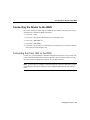
C H A PT E R
2
Installing the Router
This chapter contains hardware installation procedures for Cisco 1600 series routers and
includes the following sections:
•
•
•
•
•
Before Installing
Connecting Power and Turning On the Router
Connecting the Router to the LAN
Connecting the Router to the WAN
Connecting the Console Port
Note You might want to perform some optional installation steps that are not explained in
this chapter, including wall-mounting the router, installing the Flash PC card, connecting
an ISDN telephone, or installing a WAN interface card. These procedures are explained in
the “Optional Installations” chapter later in this document.
Before Installing
Cisco 1600 series routers are shipped to you ready for desktop mounting. Before making
the power and network connections, simply set the router on a desktop, shelf, or other flat
surface. Be sure to read the safety information in the Regulatory Compliance and Safety
Information for Cisco 1600 and Cisco 1700 Routers that came with your router.
Warning Read the installation instructions before you connect the system to its
power source.
Installing the Router 2-1
Connecting Power and Turning On the Router
Caution Do not place anything on top of the router that weighs more than
10 pounds (4.5 kg). Excessive weight on top of the router could damage the
chassis.
Warning Do not work on the system or connect or disconnect cables during
periods of lightning activity.
Connecting Power and Turning On the Router
If you turn on the router before making network connections, you can verify your
installation by checking the appropriate LEDs during the installation process.
Warning The power supply is designed to work with TN power systems.
Warning This product relies on the building’s installation for short-circuit
(overcurrent) protection. Ensure that a fuse or circuit breaker no larger than
120 VAC, 15A U.S. (240 VAC, 10A international) is used on the phase conductors
(all current-carrying conductors).
Warning This equipment is intended to be grounded. Ensure that the host is
connected to earth ground during normal use.
Follow these steps to connect the router to power and turn it on:
2-2
Step 1
Connect the DC power cable (included with the router) from the power supply
to the DC power input on the rear panel of the router.
Step 2
Connect the male end of the power cable to the power outlet.
Step 3
Connect the female end of the cable to the male receptacle on the power supply.
Step 4
On the rear panel of the router, turn ON the power by setting the switch labeled
| / O to the | position.
Step 5
Slip the wire clip over the power cord to ensure that the power cord remains
attached to the router, as shown in Figure 2-1.
Cisco 1600 Series Router Hardware Installation Guide
Connecting Power and Turning On the Router
Check the following LEDs:
•
The SYSTEM PWR LED (front panel)—On when power is being supplied
to router.
•
The SYSTEM OK LED (front panel)—On when router software is
operational. (This LED first blinks and then remains on continuously.)
•
The OK LED (rear panel, next to Flash PC card slot)—On when the Flash
memory card is correctly installed.
Figure 2-1
Power Cord Clip Attachment
H10962
Step 6
Power cord
Clip
Installing the Router 2-3
Connecting the Router to the LAN
Connecting the Router to the LAN
The router can be connected to two 10BaseT or AUI Ethernet LANs.
Warning Do not work on the system or connect or disconnect cables during
periods of lightning activity.
Warning The ports labeled 10BASET, CONSOLE, and FLASH PC CARD are
safety extra-low voltage (SELV) circuits. SELV circuits should only be connected
to other SELV circuits. Because the BRI circuits are treated like
telephone-network voltage, avoid connecting the SELV circuit to the telephone
network voltage (TNV) circuits.
Connecting to an AUI Ethernet
You must supply an Ethernet transceiver for this connection. Follow these steps to connect
the router to an AUI Ethernet LAN:
Note Some transceivers connect directly to the router AUI port. If you have this type of
transceiver, you do not need the AUI adapter cable. You can connect the transceiver to the
AUI port on the router and then go to Step 3.
2-4
Step 1
Connect the one end of the AUI adapter cable to the transceiver.
Step 2
Connect the other end of the AUI adapter cable to the AUI port on the router
(Figure 2-2).
Step 3
Connect the transceiver to the Ethernet LAN by using a BNC connector
(Figure 2-2).
Cisco 1600 Series Router Hardware Installation Guide
Connecting to an AUI Ethernet
Step 4
•
The transceiver power LED (the location depends on model)—On when
power is supplied to the transceiver through the router.
•
The LAN ACT LED (front panel)—Blinks when there is traffic on the
Ethernet LAN.
AUI Port to Ethernet Transceiver Connection (Cisco 1601 Shown)
H7197
Figure 2-2
Check the following LEDs:
DO NO
T
MODU INSTAL
LE WIT L ANY
WA
H PO
WER N
ON
Transceiver
adapter cable
Ethernet AUI port
(DB-15)
(with jackscrews
or slide-latch)
Router
Ethernet
transceiver
BNC connector
To thin
Ethernet
network
To thin
Ethernet
network
Installing the Router 2-5
Connecting the Router to the LAN
Connecting to a 10BaseT Ethernet
You must supply an Ethernet hub and an RJ-45-to-RJ-45 cable for this connection. Follow
these steps to connect the router to a 10BaseT Ethernet LAN:
Figure 2-3
Step 1
Connect one end of the Ethernet cable to the 10BASE T port.
Step 2
Connect the other end of the cable to one of the ports on the 10BaseT hub.
Step 3
Check the following LEDs:
•
LNK LED (rear panel, next to 10BaseT port)—On when the router is
correctly connected to the 10BaseT Ethernet LAN.
•
LAN ACT LED (front panel)—On when there is traffic on the Ethernet LAN.
10BaseT Port to Ethernet Hub Connection (Cisco 1601 Shown)
LN K
WI C
OK OK
DO NO
T
MODU INSTALL
LE WIT
AN
H PO Y WAN
WER
ON
10BaseT link LED
10BaseT port
AUI
8
7
H7198
1
Straight-through
Ethernet cable
2-6
10BaseT hub
Cisco 1600 Series Router Hardware Installation Guide
Cisco 1605 LAN Connections
Cisco 1605 LAN Connections
Unlike the other Cisco 1600 models, the Cisco 1605 can support two LAN connections
(Figure 2-4).
The Cisco 1605 has two Ethernet Ø ports. However, you can use only one of the Ethernet Ø
ports at any one time. A second Ethernet connection must always be on the
ETHERNET 1 10BASE T port. The Ethernet ports can be used in one of these two
combinations:
ETHERNET Ø 10BASE T and ETHERNET 1 10BASE T
ETHERNET Ø AUI and ETHERNET 1 10BASE T
Make the LAN connections for the Cisco 1605 as you would any of the other models.
Installing the Router 2-7
Connecting the Router to the LAN
Figure 2-4
Cisco 1605 with Two Ethernet LAN Connections
Ethernet AUI port
(DB-15)
(with jackscrews
or slide-latch)
LNK
OK
WIC
DO NOT
MOD
INST
ALL
ULE
WITH ANY
POW WAN
ER ON
OK OK
Router
Ethernet
transceiver
10BaseT hub
BNC connector
AUI
8
To thin
Ethernet
network
7
6
5
Straight-through
Ethernet cable
2-8
4
3
2
1
H10603
To thin
Ethernet
network
Cisco 1600 Series Router Hardware Installation Guide
Connecting the Router to the WAN
Connecting the Router to the WAN
Each Cisco 1600 series router supports a different type of WAN connection. This section
describes how to make these WAN connections:
•
•
•
•
•
Cisco 1601—Serial
Cisco 1602—Data service unit/channel service unit (DSU/CSU)
Cisco 1603—ISDN BRI S/T
Cisco 1604—ISDN BRI U
Cisco 1605—Refer to the Cisco WAN Interface Cards Hardware Installation Guide that
came with your WAN interface card.
Connecting the Cisco 1601 to the WAN
For this step, you must purchase a shielded serial transition cable from Cisco Systems. The
router end of the shielded serial transition cable has a DB-60 connector. When you order
the cable, specify the appropriate connector for your WAN interface.
Note To ensure agency compliance with electromagnetic emissions requirements, such as
electromagnetic interference (EMI), use only a shielded serial transition cable with the
router.
Installing the Router 2-9
Connecting the Router to the WAN
Follow these steps to connect the Cisco 1601 to the WAN:
Step 1
Connect the cable DB-60 connector to the SERIAL Ø port on the Cisco 1601.
Step 2
Connect the other end of the cable to one of the following devices:
Step 3
Asynchronous modem that you provide if connecting to an analog telephone
line.
•
Synchronous modem, DSU/CSU, or other data circuit-terminating
equipment (DCE) that you provide if connecting to a digital WAN line.
Check the RDY LED on the rear panel. It lights when the router is correctly
connected to the modem or DSU/CSU. If the RDY LED is not on, refer to the
“Troubleshooting” appendix later in this guide.
Serial Connection—Cisco 1601
H7199
Figure 2-5
•
LNK
RDY LED
LNK
WIC
OK OK
DO NOT
MODUL INSTAL
E WIT L ANY WA
H POW
N
ER ON
Serial transition
cable
Serial port (DB-60)
DSU/CSU or
other DCE
EIA/TIA-232, EIA/TIA-449,
V.35, X.21, or EIA-530 connector
2-10
Cisco 1600 Series Router Hardware Installation Guide
Router
Connecting the Cisco 1602 to the WAN
Connecting the Cisco 1602 to the WAN
You must provide either an RJ-48S-to-RJ-48S or an RJ-45-to-RJ-45 cable for this step.
Follow these steps to connect the Cisco 1602 to the WAN:
Step 1
Connect one end of the cable to the router SERIAL Ø 56K DSU/CSU port.
Step 2
Connect the other end of the cable to the 56-kbps wall jack (Figure 2-6).
56-kbps Service Connection—Cisco 1602
H7200
Figure 2-6
LN K
LN K
W IC
OK OK
56-kbps
DSU/CSU
port
CARRIER
LED
RJ-48S-to-RJ-48S cable
Step 3
56-kbps wall jack
Check the CARRIER LED on the rear panel. It lights when the cable is correctly
connected and the router has synchronized with the central office switch.
Installing the Router 2-11
Connecting the Router to the WAN
Connecting the Cisco 1603 to the WAN
You must provide a Network Termination 1 (NT1) device and a straight-through
RJ-45-to-RJ-45 cable for this connection.
Warning Network hazardous voltages are present in the BRI cable. If you detach
the BRI cable, detach the end away from the router first to avoid possible electric
shock. Network hazardous voltages also are present on the system card in the area
of the BRI port (RJ-45 connector), regardless of when power is turned off.
Depending on where the Cisco 1603 is being used, the ISDN BRI connection can be
different. Follow these steps to connect the Cisco 1603 to the WAN:
2-12
Step 1
Use an RJ-45-to-RJ-45 cable to connect the cable to the ISDN Ø S/T port on the
router.
Step 2
Do one of these steps:
•
In North America—Connect the other end of the cable to the NT1
(Figure 2-7), and then connect the NT1 to the ISDN wall jack (Figure 2-8).
•
Outside North America—Connect the other end of the cable directly to the
ISDN wall jack (Figure 2-8).
Cisco 1600 Series Router Hardware Installation Guide
Connecting the Cisco 1603 to the WAN
Figure 2-7
NT1 Connection—Cisco 1603
LN K
LN K
WI C
OK OK
ISDN S/T port
Router
H7201
ISDN link
OK LED
Straight-through
RJ-45-to-RJ-45 cable
NT1 device
S/T port
Installing the Router 2-13
Connecting the Router to the WAN
ISDN Wall Jack Connection—Cisco 1603
H3587
Figure 2-8
Wall jack
Straight-through
BRI cable
Warning Network hazardous voltages are present in the BRI cable. If you detach
the BRI cable, detach the end away from the router first to avoid possible electric
shock. Network hazardous voltages also are present on the system card in the area
of the BRI port (RJ-45 connector), regardless of when power is turned off.
Step 3
2-14
Check the following LEDs:
•
The OK LED on the rear panel (next to ISDN S/T port) lights when the router
has synchronized with the central office switch.
•
The external NT1 might have an LED indicating synchronization with the
central office switch or other NT1 status. Check the NT1 documentation.
Cisco 1600 Series Router Hardware Installation Guide
Connecting the Cisco 1604 to the WAN
Connecting the Cisco 1604 to the WAN
You must provide a straight-through cable, either RJ-11-to-RJ-11 or RJ-45-to-RJ-45, for
this connection. Follow these steps to connect the Cisco 1604 to the WAN:
Step 1
Connect one end of the cable to the ISDN Ø U port on the router.
Step 2
Connect the other end of the cable directly to the ISDN BRI wall jack
(Figure 2-9).
Figure 2-9
ISDN BRI Connection—Cisco 1604
LN K
LN K
LN K
WI C
LN K
OK OK
Router
RJ-45-to-RJ-45 cable
ISDN BRI
wall jack
Step 3
H7202
NT1 LED
ISDN U port
The NT1 LED on the rear panel lights when the router has synchronized with
the central office switch.
Installing the Router 2-15
Connecting the Console Port
Connecting the Cisco 1605 to the WAN
The procedure for connecting the Cisco 1605 to the WAN depends on the type of WAN
interface card that is installed in the router. For instructions for the card that you are using,
refer to the Cisco WAN Interface Cards Hardware Installation Guide that came with your
WAN interface card.
Connecting the Console Port
The cable and adapters required for this connection are included with the router. Follow
these steps to connect the router to a terminal or PC:
Step 1
Connect the light-blue console cable to the light-blue CONSOLE port on the
router (Figure 2-10).
Step 2
Use the correct adapter to connect the other end of the cable to your terminal or
PC.
Note If your terminal or PC has a console port that does not fit one of the adapters, you
must provide the correct adapter for that port.
2-16
Cisco 1600 Series Router Hardware Installation Guide
Connecting the Console Port
Connecting to Console Port
H7203
Figure 2-10
LN K
LN K
LN K
WI C
LN K
OK OK
Console port
Rollover console cable
(RJ-45-to-RJ-45)
You have completed the router installation and are ready to configure the router. Refer to
the Cisco 1600 Series Software Installation Guide for more information about configuring
your router.
Installing the Router 2-17
Connecting the Console Port
2-18
Cisco 1600 Series Router Hardware Installation Guide