1
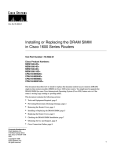
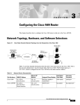
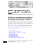
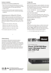
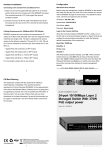
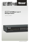
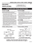
C H A PT E R
1
Overview
This chapter introduces the Cisco 1400 series router and covers the following topics:
•
•
•
•
•
•
•
Key Features
Technology Overview
Rear-Panel Ports and LEDs
Front-Panel LEDs
Router Memory
Unpacking the Router
Additional Required Equipment
The Cisco 1400 series routers are a family of ATM-25 and ADSL routers that connect small
businesses and remote branch offices to the Internet or to larger, corporate networks.
Note For definitions of the terms and acronyms used in this chapter, refer to the “Terms”
section on page 1-3 of this chapter.
Table 1-1 describes the Cisco 1400 series routers and Figure 1-1 and Figure 1-2 illustrate
the router rear panels.
Overview 1-1
i
Table 1-1
Cisco 1400 Series Router Model Comparison
Cisco 1401
Cisco 1407
Cisco 1417
• One 10BaseT interface
• One 10BaseT interface.
• One 10BaseT interface
• One ATM-25 interface for
connection to an external,
ATM 25-to-DSL modem,
providing an ADSL connection of
up to 8 Mbps to the Internet or to
corporate networks
• One standard ADSL DMT
(Issue 2) interface that supports an
ATM-cell-based ADSL connection
of up to 8 Mbps to the Internet or
to a corporate network
• One standard ADSL DMT
(Issue 2) interface that supports an
ATM-cell-based ADSL connection
of up to 8 Mbps to the Internet or
to a corporate network
• Analog Devices Incorportated
ADSL chip-set
• Alcatel ADSL chip-set
• Alcatel ASAM compatibility
• Cisco 6100 and Cisco 6200E
DSLAM compatibility.
Cisco 1401 Router Rear Panel
Cisco 1401
CONSOLE
12407
Figure 1-1
LNK
OK
FLASH PC CARD
ATM 25
Cisco 1407 and Cisco 1417 Router Rear Panel
Cisco 1417
CONSOLE
ADSL
LNK
OK
FLASH PC CARD
ETHERNET
1-2
Cisco 1400 Series Router Installation and Configuration Guide
17505
Figure 1-2
ETHERNET
Key Features
Key Features
Following are the key features of the Cisco 1400 series routers:
•
•
Ethernet port—For connecting to a 10BaseT LAN through an Ethernet hub or switch.
•
ADSL port (Cisco 1407 and Cisco 1417 routers)—For connecting directly over an
ADSL line to a central service provider.
•
Console port—For connecting a terminal or PC to configure and manage the router.
Supports up to 9600 bps (up to 115.2 kbps for software download).
•
•
•
•
Supports IP, IPX, PPP over ATM, and firewall security.
ATM-25 port (Cisco 1401 router)—For connecting through a DSL modem over an
ADSL line to a central service provider.
Supports ATM features such as ATM Adaption Layer 5, ATM PVCs, and RFC 1483.
Supports SNMP for management over an SNMP network.
Supports Cisco ATM Management Information Base (MIB).
<<Reviewers: Do we need to add more features here for the lastest SW
releases?>>
Terms
These are some key ADSL elements and terms you should know:
•
Asymmetric Digital Subscriber Line (ADSL)—One of several kinds of digital
subscriber line (DSL) technologies that together are referred to as xDSL. ADSL is made
up of three channels:
— High-speed (up to 8 Mbps) downstream data channel
— Lower-speed (up to 1 Mbps) upstream data channel
— Standard telephone service channel
•
ATM subscriber access multiplexer (ASAM)—A telephone central office multiplexer
that supports ASDL ports over a wide range of network interfaces. An ASAM sends and
receives subscriber data (often Internet services) over existing copper telephone lines,
Overview 1-3
Key Features
concentrating all traffic onto a single high-speed trunk for transport to the Internet or the
enterprise intranet. A device similar to a DSLAM; different manufacturers use different
terms for similar devices.
•
Asynchronous Transfer Mode (ATM)—A connection-oriented data transfer mode that
segments data into fixed cell-lengths (53 bytes), transports the cells, and reassembles
them at the destination. ATM does not limit how fast data can be transferred over a
connection. The fixed-cell-size feature enables ATM to send any type of data efficiently.
•
•
Protocol: ATM, any AAL, 25-, 155- or 622-Mbps internal ATM multiplexing bus.
•
Discrete Multi-Tone (DMT)—The American National Standards Institute
(ANSI)-specified method of data signal modulation for ADSL.
•
Internet service provider (ISP)—A company that provides other companies or
individuals with access to, or presence on, the Internet.
•
Microfilter—A device that prevents certain router frequencies from travelling over the
telephone line and interfering with telephone calls. For information on the type of
microfilter to use with your router, contact your service provider or Cisco reseller.
•
Point-to-Point Protocol (PPP)—A protocol that transfers data over a WAN using
bidirectional synchronous or asynchronous connections between two endpoints. PPP
controls the call setup between the Cisco 1400 series router and the remote device. PPP
enables the Cisco 1400 series router to multiplex various protocols over individual
virtual connections. IP and IPX packets can be sent over PPP with ATM establishing the
connection between the two devices.
•
Permanent virtual connection (PVC)—ATM requires that a circuit (or connection) is
established that will pass data between the two devices. This connection is not a
physical connection but a logical or virtual connection.
Digital subscriber line access multiplexer (DSLAM)—A telephone central office
multiplexer, such as the Cisco 6200, that supports ADSL ports over a wide range of
network interfaces. A DSLAM sends and receives subscriber data (often Internet
services) over existing copper telephone lines, concentrating all traffic onto a single
high-speed trunk for transport to the Internet or the enterprise intranet. A device similar
to an ASAM; different manufacturers use different terms for similar devices.
The Cisco 1400 series router supports PVCs to establish an end-to-end connection to
the remote device. The router does not support switched virtual connections (SVCs).
1-4
Cisco 1400 Series Router Installation and Configuration Guide
Technology Overview
•
•
“Plain old telephone service” (POTS)—Basic telephone service.
•
SNMP—Simple Network Management Protocol
POTS splitter—A device (or one part of a larger device) that enables both an ADSL data
device (for example, a Cisco 1400 series router) and a standard analog device (such as
a telephone) to share the same ADSL line. For information on the type of POTS splitter
to use with your router, contact your service provider or Cisco reseller.
Technology Overview
An ADSL line is a DSL that transfers data from the telephone central office to the user
much faster than the user sends data to the telephone central office. ADSL is ideal for
applications such as high-speed Internet access and video-on-demand, in which the server
sends much more data than the client sends. Internet users, in general, download more
information from the Internet than they upload.
One of the key features of ADSL is that it operates over existing standard telephone wires,
enabling simultaneous voice and data transmissions over the same telephone line.
ATM over ADSL
The Cisco 1400 series routers use ATM over ADSL to transfer data to and from remote
networks, such as an ISP or corporate network.
By using ATM, the router can maintain a communication session with the remote location
until the session ends. A continuous connection results in a higher quality of service than
that of many other data protocols.
Overview 1-5
Technology Overview
Network Example
Figure 1-3 illustrates a network that includes a Cisco 1400 series router.
A Cisco 1401 router connects to the ADSL line through a DSL modem. (The Cisco 1407
and Cisco 1417 routers do not require the modem.) Some DSL modems have an integrated
POTS splitter, which connects a phone or fax machine to the same ADSL line as the router.
If you are using a telephone and the Cisco 1407 or Cisco 1417 router on the same telphone
line, an external POTS splitter is required for optimal performance. A splitter reduces
possible interference on both data connections and voice calls, which use different
frequencies. For more information, refer to the “Using POTS Splitters and Microfilters”
section in the “Installation” chapter later in this guide.
Figure 1-3
Network with the Cisco 1400 Series Router
Corporate
network
Public
telephone
network
Internet
ATM-25 DSL
modem
POTS
splitter Data
(optional)
DSL service provider
central office
Voice
Cisco 1400
series router
Required only for
Cisco 1401
Hub
Server
PCs
1-6
Cisco 1400 Series Router Installation and Configuration Guide
12630
Phone
Rear-Panel Ports and LEDs
Rear-Panel Ports and LEDs
Figure 1-4 and Figure 1-5 illustrate the ports and LEDs on the rear panel of the Cisco 1400
series routers. Table 1-2 describes the rear-panel port functions, and Table 1-3 describes the
LEDs.
Cisco 1401 Rear-Panel Ports and LEDs
Flash PC card
OK LED
Flash PC card slot
Console port
ATM 25 port
Cisco 1401
CONSOLE
I
LNK
0
OK
FLASH PC CARD
ATM 25
ETHERNET
12408
Figure 1-4
Eject button
10BaseT 10BaseT
link LED Ethernet
port
Cisco 1407 and Cisco 1417 Rear-Panel Ports and LEDs
Flash PC card
OK LED
Flash PC card slot
ADSL port
Console port
Cisco 1417
ADSL
CONSOLE
I
LNK
0
OK
FLASH PC CARD
ETHERNET
17503
Figure 1-5
Power switch Power socket
Eject button
10BaseT 10BaseT
link LED Ethernet
port
Power switch Power socket
Overview 1-7
Rear-Panel Ports and LEDs
Table 1-2
Rear-Panel Ports
Port
Label/Color
Description
Ethernet port
ETHERNET
(yellow)
Connects the router to the local 10BasetT Ethernet network.
ATM
(Cisco 1401 router)
ATM 25
(green)
Connects the router to the DSL modem. The DSL modem
connects the router to the ADSL line.
ADSL
(Cisco 1407 and
Cisco 1417 router)
ADSL
(purple)
Connects the router directly to an ADSL line or to an ADSL line
through a POTS splitter. The POTS splitter enables the router and
a telephone to share the ADSL line.
Console port
CONSOLE
(blue)
Connects the router to a terminal, terminal server, or PC for
software configuration.
Flash PC card slot
FLASH PC CARD
If not already installed, insert the Flash PC card into this slot.
Power socket
Input: 100-240 VAC~
Freq: 50/60 Hz
Current 1.2-0.6 A
1,2-0,6 A
Watts: 40W
Connects the router to the power supply.
Table 1-3
Rear-Panel LEDs
LED Label
Color
Description
OK
Green
On means that the Flash memory card is correctly inserted in the Flash
PC card slot.
LNK
Green
On means that the router is connected to the Ethernet LAN through the
10BaseT Ethernet port.
1-8
Cisco 1400 Series Router Installation and Configuration Guide
Front-Panel LEDs
Front-Panel LEDs
Use the front-panel LEDs to determine network activity and status on the Ethernet port and
the WAN port. Figure 1-6 illustrates these LEDs, and Table 1-4 describes them.
Figure 1-6
Front-Panel LEDs
Cisco 1400
PWR
OK
SYSTEM
Table 1-4
LED Label
ACT
COLL CARRIER
ETHERNET
ACT
WAN
LP
12409
S E R I E S
Front-Panel LEDs
Color
Description
PWR
Green
On when DC power is being supplied to the router.
OK
Green
On when the router has successfully booted up and the software is functional.
This LED blinks during the power-on self-test (POST).
ACT
Green
Blinks when there is network activity on the Ethernet LAN.
COLL
Yellow
Blinks when there are network (packet) collisions on the Ethernet LAN.
CARRIER
Green
On steady when the router has synchronized with the equipment connected to
the ATM-25 port (Cisco 1401 router) or the ADSL equipment at the service
provider office (Cisco 1407 and Cisco 1417 routers).
ACT
Green
Blinks when data is being sent to or received from the ATM-25 port (Cisco 1401
router) or the ADSL port (Cisco 1407 and Cisco 1417 routers).
LP
Yellow
On steady when the ATM-25 port (Cisco 1401 router) or the ADSL port
(Cisco 1407 and Cisco 1417 routers) is in loopback mode.
SYSTEM
ETHERNET
WAN
Overview 1-9
Router Memory
Router Memory
This section describes the types of memory used by the router and how to find out how
much of each type the router is using.
Memory Types
The Cisco 1400 series routers have the following types of memory:
1-10
•
Dynamic RAM (DRAM)—This is the main storage memory for the router. DRAM is
also called working storage and contains the dynamic configuration information. The
Cisco 1400 series router operates from DRAM.
•
Nonvolatile RAM (NVRAM)—This type of memory contains a backup copy of your
configuration. If the power is lost or the router is turned off, this backup copy enables
the router to return to operation without reconfiguration.
•
Flash memory—This special kind of erasable, programmable ROM contains a copy of
the Cisco IOS software. The Flash memory structure can store multiple copies of the
Cisco IOS software. You can load a new level of the operating system in every router in
your network and then, when convenient, upgrade the whole network to the new level.
The Flash memory on the Cisco 1400 series router is stored on a Flash PC card.
Cisco 1400 Series Router Installation and Configuration Guide
Displaying Memory Amounts
Displaying Memory Amounts
Use the show version command to view the amount of NVRAM, DRAM, and Flash
memory stored in your router. Below is an example of the show version command. The
command output in bold text displays the memory amounts for this router.
1401# show version
Cisco Internetwork Operating System Software
IOS (tm) 1400 Software (C1400-NSY-M),Version 12.0(19980714:220727)
Copyright (c) 1986-1998 by cisco Systems, Inc.
Compiled Wed 15-Jul-98 10:56 by cisco
Image text-base: 0x02005000, data-base: 0x024E9ECC
.
.
.
cisco 1401 (68360) processor (revision A) with 9216K/3072K bytes of
memory.
Processor board ID 04618030, with hardware revision 00000000
Bridging software.
X.25 software, Version 3.0.0.
1 Ethernet/IEEE 802.3 interface(s)
1 ATM network interface(s)
System/IO memory with parity disabled
8192K bytes of DRAM onboard 4096K bytes of DRAM on SIMM
System running from RAM
8K bytes of non-volatile configuration memory.
4096K bytes of processor board PCMCIA flash (Read/Write)
Configuration register is 0x2
Overview 1-11
Unpacking the Router
Unpacking the Router
Figure 1-7 shows the items that come in the router accessory kit. Contact your Cisco
reseller if anything is missing from your accessory kit.
Figure 1-7
Router Box Contents
n
atio
ent
cum -ROM
D
C
Cisco 1400
S E R I E S
PWR
OK
SYSTEM
ACT
COLL CARRIER
ETHERNET
ACT
LP
AL
WAN
Do
Installa
tion
and
gurati
o
Guide n
Confi
Quick
Start
Guide
Cisco 1400 router
Product documentation
Power cord (black)
DB-9 to RJ-45 console adapter
1-12
DB-25 to RJ-45 console adapter
Ethernet cable
(yellow, RJ-45 to RJ-45)
ATM 25 cable
(green, RJ-45 to RJ-45)
(Cisco 1401 router)
ADSL cable
(purple RJ-11 to RJ-11)
(Cisco 1407 and Cisco 1417 routers)
POTS crossover cable (if ordered)
(purple with blue stripe, RJ-11 to RJ-11)
Cisco 1400 Series Router Installation and Configuration Guide
12410
Console cable
(light blue, RJ-45 to RJ-45)
Additional Required Equipment
Additional Required Equipment
Table 1-5 is a list of other equipment that you need to completely install your router.
Table 1-5
Additional Requird Equipment
Equipment
When You Use It
10BaseT Ethernet hub or
10BaseT Ethernet switch
Hubs and switches connect multiple pieces of network equipment (including the
Cisco 1400 series router) to create a network.
You need either a hub or switch, not both, to connect your router to the LAN.
ATM-DSL modem
(Cisco 1401 router)
An ATM-DSL modem (for example, a Cisco 625 or Cisco 626) connects
ATM-based devices (such as the Cisco 1401 router) to ADSL lines.
Some DSL modems include an integrated POTS splitter, which connects the
router and a telephone or fax machine to the same ADSL line.
If you are not sure what type of DSL modem to use with your router, contact
your ADSL service provider or your Cisco reseller.
RJ-11-to-RJ-11 cable
(Cisco 1401 router only)
This cable connects a DSL modem (used with the Cisco 1401 router) to the
ADSL line. You might need to provide one if it is not included with the modem.
POTS splitter
(Cisco 1407 and
Cisco 1417 routers)
Optimal router and telephone performance (when the router and telephone are
used on the same telephone line) requires a POTS splitter. A splitter reduces
interference that might occur on data connections and voice calls. Some types of
splitters can be used to connect analog devices, such as a telephone or fax
machine, to the same ADSL line as the router. For more information, refer to the
“Using POTS Splitters and Microfilters” section in the “Installation” later in this
guide.
If you are not sure what type of splitter to use, contact your service provider or
your Cisco reseller.
Microfilter(s)
(Cisco 1407 and
Cisco 1417 routers)
Microfilters can be used (in addition to a POTS splitter) to further reduce
interference on a voice call. Refer to the “Using POTS Splitters and
Microfilters” section in the “Installation” later in this guide for detailed
information on when to use microfilters with the Cisco 1417 router.
If you are not sure what type of microfilter to use, contact your service provider
or your Cisco reseller.
Overview 1-13
Additional Required Equipment
1-14
Cisco 1400 Series Router Installation and Configuration Guide