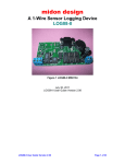
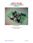
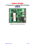
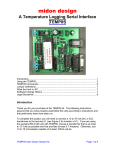
1
midon design A 1-Wire Serial Interface TEMP08 Figure 1 TEMP08 TEMP08 User Guide Version 4.0x November 27, 2014 TEMP08 User Guide Version 4.0x Page 1 of 25 midon design 1. Table of Contents 1. Table of Contents ..........................................................................................2 1.1. List of Tables ..........................................................................................3 1.2. List of Figures .........................................................................................3 2. Introduction ....................................................................................................4 3. Installation......................................................................................................5 4. Using the TEMP08.........................................................................................7 5. TEMP08 Commands ...................................................................................10 5.1. Using the SET Command .....................................................................12 Update Interval ............................................................................................12 5.2. The DISplay Output ..............................................................................13 5.2.1. DIS output explanations ................................................................14 5.3. TMP Output Display .............................................................................15 5.4. Missing Sensor Display ........................................................................17 5.5. Discrete Option Commands..................................................................18 5.5.1. Once Per Minute Time Display (ETI) .............................................18 5.5.2. Temperature Display from DS2438 (ETE).....................................18 5.5.3. Display Wind from DS2450 (EWN)................................................18 5.5.4. Wind Direction Reverse (WDR).....................................................18 5.5.5. Set Poll Time (SPT).......................................................................18 5.5.6. Set Temperature Display (STD) ....................................................18 5.5.7. Serial Number Display (SID) .........................................................19 5.6. Set North Command (NOR)..................................................................19 5.7. Delete Command (DEL) .......................................................................19 5.8. Erase EEPROM command (ERA) ........................................................19 5.9. Reset Counter Command (RST) ..........................................................19 5.10. Display Time Command (TIM) ..........................................................20 5.11. DS2408 Sensor Usage .....................................................................20 5.11.1. Relay Sensors............................................................................20 5.11.2. LED Sensors..............................................................................20 5.11.3. Input Sensors.............................................................................20 6. Software ......................................................................................................21 6.1. Software Change History......................................................................21 6.2. Upgrading TEMP08 Software ...............................................................21 7. Trouble-Shooting Problems with TEMP08...................................................21 8. Error Messages ...........................................................................................23 9. Schematic ....................................................................................................24 10. Conclusion ...............................................................................................25 11. Legal Disclaimer.......................................................................................25 TEMP08 User Guide Version 4.0x Page 2 of 25 midon design 1.1. List of Tables Table 1 TEMP08 Command List .........................................................................10 Table 2 Sensor Type Descriptions ......................................................................15 Table 3 TEMP08 Software History......................................................................21 Table 4 Common TEMP08 Problems and Resolutions.......................................21 Table 5 TEMP08 Error Messages.......................................................................23 Table 6 Reset Type Messages ...........................................................................23 1.2. List of Figures Figure 1 TEMP08..................................................................................................1 Figure 2 DS18S20/DS18B20 Pin-out....................................................................6 Figure 3 TEMP08 Parts Placement.......................................................................7 Figure 4 TEMP08 Schematic ..............................................................................24 TEMP08 User Guide Version 4.0x Page 3 of 25 midon design 2. Introduction Thank you for your purchase of the TEMP08 1-Wire Serial Interface. The following instructions will assist you in configuring and operating the product. TEMP08 is a stand-alone 1-Wire interface providing standard serial commands to control the Dallas/Maxim 1-Wire bus and the devices used on it. Sensors can be polled on a regular basis (from 1 to 99 minutes), or manually interrogated. In a typical application, TEMP08 is connected to a serial port on a PC. Serial interface software is then used to gather the data received from TEMP08 and process it. Many users have interfaced TEMP08 into the HomeSeer product, which can be used to automate lights, HVAC, sprinklers, and other devices, based on the sensor readings from TEMP08. The TEMP08 can provide a serial interface for the following 1-Wire devices: • Multiple DS2438-based Humidity Sensors • Multiple DS2438 based Barometric Sensors of the Bray-Jennings design • Multiple DS2438 general purpose sensors for analog voltage input • Multiple DS2438-based Solar sensors • Multiple DS18S20, DS18S20-PAR, DS18B20, DS1822, DS1920 temperature sensors as well as, temperature readings from any DS2438 • Multiple DS2450 voltage sensors • Multiple DS2423 based rain gauges • Multiple DS2423 general purpose counters (for use with Lightning sensors and other types of counter inputs) • Multiple DS2401 or DS1990 1-Wire serial numbers (only presence will be reported) • Up to 20 1WIO relay interface modules (available from Midon Design) or equivalent DS2408 based relay module • Up to 10 1WIO LED modules (available from Midon Design) • Up to 20 1WIO Input modules (available from Midon Design) or equivalent DS2408 based input module • One DS2450 based Weather Station for wind speed and wind direction For more information on these sensors, please refer to the Midon Design 1-Wire Application Guide available on our website. TEMP08 has the following features: TEMP08 User Guide Version 4.0x Page 4 of 25 midon design • On-board DS2438 voltage and temperature sensor • Jumper-less provisioning - all configuration settings are stored in non-volatile memory • Up to 60 1-Wire are sensors supported • Simple instruction set with a Help (HLP) prompt for recalling command names • Easy to delete sensors, if they are no longer required, using the DEL command • 1-Wire bus errors, such as shorted wires, are flagged when they occur • Support for software serial flow control (Control-S, Control-Q) to permit inspection of long lists without scrolling beyond your terminal’s page length • Continuous poll for presence of sensors. TEMP08 will notify you when any sensor is connected or disconnected, providing that they have been previously recognized by TEMP08 via the INI command. This may be useful for locating intermittent 1-Wire bus problems or identifying which sensor is which. • Manual Poll of sensor readings. While TEMP08 is normally used for regular (from 1 to 99 minute intervals) polling of sensor readings, it may also be used manually to take sensor readings on command from the serial interface. 3. Installation To complete this project, you will need to connect a 12 to 16 Volt (AC or DC) transformer to the terminal J1 (see Figure 3 or 4 for the location of J1). If you intend to power 1WIO relay units from the 12V output of TEMP08, the transformer needs to supply at least 350mA (250mA for 1WIO and 100mA for TEMP08) per 1WIO relay unit, up to a maximum of 800mA, or 2 1WIO relay units. Beyond that, supplemental powering will need to be provided for the offboard units. Otherwise, any 12 to 20 Volt adapters capable of at least 100mA will do. ALTERNATIVELY, to power this project, you could to connect a 5Volt DC power supply via a standard USB A to B cable to the connector J2 (see Figure 3 or 4 for the location of J2). Make sure that the power supply can provide at least 50mA of current. Do not use both J2 and J1 powering – only one can be used. If you choose to use 5VDC from J2, then the J3 12Volt power output will not be available. If you are using a sensor network of 1-Wire devices, connect them now to connector J3. If you are using DS18S20 or DS18B20 temperature sensors, only 2 pins of each sensor needs to be connected, however a connection is required between the VDD and GND pins of the sensor if you are using parasitic powering. If +5VDC TEMP08 User Guide Version 4.0x Page 5 of 25 midon design local power is being used to power the sensor, connect the VDD terminal to it. See Figure 2 for device connections. Figure 2 DS18S20/DS18B20 Pin-out TEMP08 User Guide Version 4.0x Page 6 of 25 midon design Figure 3 TEMP08 Parts Placement 4. Using the TEMP08 TEMP08 User Guide Version 4.0x Page 7 of 25 midon design Connect up a straight-through serial cable between TEMP08's J4 connector and your PC. Open up HyperTerminal (or equivalent terminal emulator program) on your PC. Configure it to 9600 BPS, No parity, 8 bits, 1 start bit and NO hardware handshaking (very important!). Power up the TEMP08 and configure the unit for the devices that you have connected. We recommend that you next use the ERA command for first time use, to erase the EEPROM. This will remove any previous information that may have been stored in the EEPROM. Next use the INI command to search for any 1-Wire devices connected to the 1-Wire bus. If you get any error messages, it is most likely a result of a bad connection to the devices. Verify them. Typically, a "OW bus error" message indicates that a sensor has been installed in reverse, or that there is a short on the bus. The INI command is used to search for any new sensors that are present on the 1-Wire bus. Upon completion, the serial number of any new sensor is stored in permanent memory on the TEMP08 and that sensor is available for interrogation by the polling process. Note: an ERA command is not required every time that an INI command is issued. It should only be required for first time use. If a DS2408, DS2423 or DS2438 is detected by the INI command, you may get an error message that requests you to input the unit TYPe. See the table 2 for details for the valid inputs. If nothing is entered for 1 minute in this field for a DS2423, then the sensor TYPe will default to “C” (Counter). A DS2438 will default to “V” (Voltage) if the same timeout occurs. A DS2408 will remain as an unknown type, until you manually configure it. Now would be a good time to set the clock using the SCK command. Follow the prompts and input the correct time in 24 hour format (for example, 2PM is 14:00). Now program the configuration by using the SET command. Just type SET and the program will prompt you for the required option settings. To verify that your setup is working properly, you should next use the TMP command to perform an immediate sensor reading. The output of the TMP command should look like the sample below (the exact output will depend on what type of sensors and how many you have installed). > WED 21:51:13 Reading Sensors... Humidity #01[9F00000037555326]=60% Barometer #01[A900000037621A26]=28.21 inHg Voltage #01[020000002B2CB326]=02.60V 05.03V 00mV Wind Dirn[9F00000001087320]= NNW Wind Speed[8E00000001562C1D]=00 MPH, Gust = 00 TEMP08 User Guide Version 4.0x Page 8 of 25 midon design Rain #01[8E00000001562C1D]=003.32 Inch Counter #01[D4000000045C621D]=00000029 00024592 1WIO Status #01 [A400000001042829] = On,Off,On,Off Temp #01[9900080049199310]=79.80F Temp #02[5C00080009242E10]=75.80F Temp #03[9F00000037555326]=79.00F Temp #04[A900000037621A26]=78.77F Temp #05[21000000032E4E22]=76.66F Temp #06[020000002B2CB326]=76.10F > If there are no apparent errors, you are ready to use TEMP08. Enjoy! TEMP08 User Guide Version 4.0x Page 9 of 25 midon design 5. TEMP08 Commands These commands are valid for v4.0x versions of TEMP08 software. Table 1 TEMP08 Command List Command Description DEL Delete a sensor that was previously installed via the INI command DIS Display serial numbers of all configured 1Wire devices ERA Erase the EEPROM ETE Enable Temperature displays from DS2438 devices ETI Enable Once-Per-Minute Time Display EWN Enable Wind Direction display for DS2450 sensors FAC Restore to factory settings. Erase the EEPROM, reset the clock to 00:00, and perform an INI function. USE WITH CAUTION. HLP Display a list of available commands INI Search for a list of available 1-Wire sensors. INP Display the status of bits 4-7 of all connected DS2408’s (See 1WIO sensor for details) configured as TYPe “I” LED Actuate a specific LED on a 1WIO LED unit or equivalent DS2408 LED interface configured as TYPe “L” TEMP08 User Guide Version 4.0x Syntax DEL<sensorid> Note 1 DIS ERA ETE<on|off> ETI<on|off> EWN<on|off> FAC HLP INI INP LED <LED number> <on|off> Where <LED number> = 01 to 80 or A for All (the leading zero is required for LED numbers less than 10) Page 10 of 25 midon design Command Description NOR Set North for a DS2450-based Weather Station RLY Actuate a specific 1WIO relay, or bits 0 to 3 of any connected DS2408 configured as TYPe “O” Syntax NOR RLY <relay number> <on|off> Where <relay number> = 01 to 80 or A for All (the leading zero is required for relay numbers less than 10) RST Reset both DS2423 counters RST<sensorid> SCK Set Clock SCK dd, hh, mm, ss<cr> dd = 01 to 07 (Sunday = 01) hh = 00 to 23 mm = 00 to 59 ss = 00 to 59 Note 2 SET Configure all system parameters SID Show the Serial Number ID for the 1-Wire Devices SID <on|off> SPT Set the polling interval SPT xx Where xx is a decimal number from 00 to 99. 00 will disable polling. STD Set Temperature Display type STD <F|C> TIM Display Time from Real Time Clock TIM TMP Display sensor readings of all connected 1Wire Devices in either verbose (includes serial numbers) or non-verbose manner TYP Select the type of DS2408, DS2438 or DS2423 device. See table 2 for valid parameters. VER Displays the current version of the software loaded WDR Wind Direction Reverse (in case your Wind Direction PCB is installed upside down, or in case you want to show the FROM direction instead of the TO direction). TEMP08 User Guide Version 4.0x SET TMP TYP<sensorid> VER WDR <on|off> Page 11 of 25 midon design Command Description ZZZ Performs a soft reset of TEMP08 Syntax ZZZ Notes 1. The <sensorid> parameter in some commands above refers to the sensor number as shown via the DIS command. See the DIS command explanation below. 2. Most commands do not require a Carriage Return (enter) following the parameter or command input. One exception is the SCK command. Commands requiring a sensor number input will require a CR if the sensor number is only a single digit. 3. Command parameters are shown in angled brackets “< >”. Where only certain options are permitted, they are indicated with a vertical pipe character “|”. 5.1. Using the SET Command The SET command has multiple parameters. All parameters are also adjustable via discrete commands. Update Interval This parameter determines the time between sensor readings. Set this parameter to 00 to stop polling. Enter the time in decimal minutes. Use the SPT command to adjust only this parameter. Temp Display This parameter determines how temperature readings are displayed. Enter F for Fahrenheit or C for Celsius. Use the STD command to adjust only this parameter. Serial # Display Set this to On if you want TEMP08 to display the 1-wire ID of all sensors during the DIS display or poll display. Use the SID command to adjust only this parameter. Wind Dirn Reverse (Wind Direction Reverse) This parameter is normally set to Off. Set this to On if you accidentally installed the wind direction PCB upside down in your weather station OR if you want to display wind direction as the FROM direction instead of the TO direction. Use the WDR command to adjust only this parameter. DS2438 Temp Display TEMP08 User Guide Version 4.0x Page 12 of 25 midon design This option will determine if DS2438’s are queried for their temperature display. DS2438’s are used for many other sensor types and there are times when displaying their temperature may not be desired. If this is the case, the display of these temperatures can be suppressed by setting this option off. Use the ETD command to adjust only this parameter. Regular Time Display This option, when set to on, will provide a once-per-minute time display output from TEMP08. Set the option to Off to suppress this time display. Use the ETI command to adjust only this parameter. Display Wind This option is used to enable or disable Wind Direction conversion from the first connected DS2450 sensor. DS2450’s are used in older versions of weather stations for wind direction sensing. Set the option to On to enable this display of wind direction. Use the EWN command to adjust only this parameter. Set Clock Enter the current time here as Day of week (01 = Sunday) followed by Hour, Minutes, and lastly, Seconds. Use the SCK command to adjust the clock at any time. Time is entered and displayed in 24 hour (military) format. 5.2. The DISplay Output Sample DIS Output TEMP08 v4.04 2014-11-26 MidonDesign.com 01 3000000002202920 DS2450 02 91000800135B9B10 DS1820 03 440000001EC34228 DS18B2 04 590000000007B014 DS2430 05 21000000032E4E22 DS1822 06 060000003770D026 DS2438 07 D1000000F5868801 DS2401 08 A400000001042829 DS2408 09 000000000107A829 DS2408 10 9700000000328329 DS2408 11 C200000016A78605 DS2405 12 3D0000000C8C351D DS2423 13 DB0000007520A126 DS2438 14 F5000000B6435726 DS2438 OK OK OK OK OK OK OK OK OK OK OK OK OK OK P P P P P P P P P P P P P P B ? ? ? C V V Sensors = 14 Poll interval = 01 minutes Temp disp = F TEMP08 User Guide Version 4.0x Page 13 of 25 midon design Serial # disp = On Wind dirn rev = Off DS2438 Temp Display = On OnBoard ADC = On Regular Time Display = Off Display Wind = On SUN 00:00:59 > 5.2.1. DIS output explanations Sensor numbers do not necessarily match up with the output from the regular sensor output readings. This is intentional. The sensor numbers in the DIS output are the memory locator and are used by the DEL and RST commands. The sensor numbers in the scan output are sequential numbers for each type of sensor. The Sensor numbers from the DIS display are also used for displaying when a sensor is removed or added to the 1-Wire bus. For instance: >MON 09:52:34 Missing Sensor #04 [9900080049199310] Would indicate that the 4th sensor in the DIS display was disconnected. >MON 09:57:01 Restored Sensor #04 [9900080049199310] Would indicate that the 4th sensor in the DIS display had been re-connected. In the remainder of the DIS display, an OK will be displayed following the sensor type to indicate that the Cyclic Redundancy Counter (CRC) checksum of the sensor's serial number is good. If the serial number has a bad CRC, an NG will be displayed. The checksum is validated during the output of the sensor display. Following the CRC status, a P or M will be displayed to show the connectivity of the sensor. A P is displayed is the sensor is present, and an M when it is missing from the 1-Wire bus. Letters following the P or M for DS2408, DS2423 and DS2438 sensors indicate the TYPe of sensor equipped. This is a one-time manual input and will be set following first discovery of the sensor via the INI command, and also following a power-up of the TEMP08 for the DS2423 sensors that do not have built-in battery backup. DS2408’s need to manually set whenever power is removed from those sensors. DS2438’s are set once and do not lose their setting even if power is removed. Any of these sensor types that have not been designated via the TYPe command will have a question mark (“?”) displayed to indicate that the setting is still required. TEMP08 User Guide Version 4.0x Page 14 of 25 midon design The letters designate the sensor type per the following table. Table 2 Sensor Type Descriptions Designation Description 1-Wire Device B Barometric Sensor DS2438 C Generic Counter Sensor DS2423 H Humidity Sensor DS2438 I Input 1WIO DS2408 L LED 1WIO DS2408 O Output (Relay) 1WIO DS2408 R Rain Sensor DS2423 T Temperature only from DS2438 DS2438 V Voltage Sensor DS2438 W Wind Speed Sensor DS2423 ? TYPe has not been set Any Following a display of the sensors installed, the output of the DIS display then shows the TEMP08 settings that you entered via the SET command. 5.3. TMP Output Display The TMP output and polled output displays are identical. An example is shown below. > WED 21:51:13 Reading Sensors... Humidity #01[9F00000037555326]=60% Barometer #01[A900000037621A26]=28.21 inHg Voltage #01[020000002B2CB326]=02.60V 05.03V 01mV Voltage #02[0100000001096420]= 02.50V,03.00V,01.02V,05.01V Wind Dirn[9F00000001087320]= NNW Wind Speed[8E00000001562C1D]=00 MPH, Gust = 00 TEMP08 User Guide Version 4.0x Page 15 of 25 midon design Rain #01[8E00000001562C1D]=003.32 Inch Counter #01[D4000000045C621D]=00000029 00024592 1WIO Status #01 [A400000001042829] = On,Off,On,Off Temp #01[9900080049199310]=79.80F Temp #02[5C00080009242E10]=75.80F Temp #03[9F00000037555326]=79.00F Temp #04[A900000037621A26]=78.77F Temp #05[21000000032E4E22]=??? Temp #06[020000002B2CB326]=76.10F > The output starts with a time reading, followed by humidity, barometer, voltage, wind direction, wind speed, counter readings, 1WIO input status, and ends with all temperature sensors. All DS2438 temperature readings will be displayed in addition to the other temperature sensors, only if the ETD option has been set to On. Note that in the example above, Temperature sensor #5 shows “???” which indicates that this sensor was not detected during the poll. Humidity readings are displayed in percent Relative Humidity. Barometric pressure sensors are displayed in Inches of Mercury. The first voltage reading displayed for a DS2438 Voltage sensor is always the external voltage from the DS2438 input. This is followed by the VDD (supply) voltage and lastly by the voltage from the on-board current sensor. Changing a humidity or barometric sensor type to a voltage type may be useful for troubleshooting problems with a sensor. Voltage readings for any DS2450 sensors are displayed after any DS2438 voltage sensors. All four channels of voltage input for DS2450’s are displayed, A channel first, ending with D channel. Wind direction is expressed via the 16 cardinal points of the compass: N NNE NE ENE E ESE SE SSE S SSW SW WSW W WNW TEMP08 User Guide Version 4.0x Page 16 of 25 midon design NW NNW In order for these cardinal points to line up to correct North, you must initialize the TEMP08 first by manually (physically) setting the Wind vane to point to North and then use the NOR command to save that direction in memory. Wind speed is shown as an average of the speed over the previous polling interval. The Gust speed is the maximum speed in any 1-minute period of any polling interval. If the polling interval is set to one minute via the SPT command, then the gust speed will not be displayed. Rain is displayed in Inches and assumes that your rain gauge counter is calibrated to count once for every 0.01 inch of rain. Rainfall is measured from the time of the last reset (RST command) of the rain gauge. General-purpose counters are used for many things. Both A and B counters of the connected DS2423 sensor are displayed. Counts are based on the number of counts stored in the DS2423 since the last reset (RST command) of the counter. The 1WIO status displays the current input status of connected DS2408’s configured via the TYP command to be of the “I” type. 5.4. Missing Sensor Display TEMP08 continuously polls for the presence of all sensors that have been INI’d (initialized), in other words, for sensors that are known to TEMP08. If any of the sensors are detected as missing, the following display will result: >MON 09:52:34 Missing Sensor #04 [9900080049199310] When the sensor is re-connected, the display will look like this: >MON 09:57:01 Restored Sensor #04 [9900080049199310] Polling of sensors is done sequentially and very fast (milliseconds per sensor). The more sensors that are equipped, however, the more time it will take for TEMP08 to recognize a missing or re-added sensor. It is normal to experience missing sensors from time to time due to noise on the 1-Wire bus. If any particular sensor shows very high disconnect readings, you might want to check the wiring for that particular sensor. TEMP08 User Guide Version 4.0x Page 17 of 25 midon design 5.5. 5.5.1. Discrete Option Commands Once Per Minute Time Display (ETI) Another option is to enable or disable the once-per-minute time display. The command ETI on enables the display. 5.5.2. Temperature Display from DS2438 (ETE) Another option is to enable or disable the temperature display resulting from the on-chip temperature sensors present on DS2438 devices. If enabled, this temperature will be included in the normal poll or TMP display. If disabled the temperature display is suppressed. The command ETE on enables the display. 5.5.3. Display Wind from DS2450 (EWN) If enabled (EWN on), the first connected DS2450 will be assumed to be a Weather Station wind direction sensor and other DS2450’s will be displayed as voltages. If disabled (EWN off), only voltages will be displayed from all DS2450’s. The command EWN on will enable the display of wind direction. With EWN set to on, the polled output (or TMP output) will look like this: Wind Dirn[9F00000001087320]= NNW With EWN set to off, the polled output will look like this: Voltage #01[05300000CD2C1220]=02.60V 05.03V 1.38V 4.25V 5.5.4. Wind Direction Reverse (WDR) This parameter is normally set to Off. Set this to On if you accidentally installed the wind direction PCB upside down in your weather station OR if you want to display wind direction as the FROM direction instead of the TO direction. 5.5.5. Set Poll Time (SPT) This parameter determines the time between sensor readings. Set this parameter to 00 to stop polling. Enter the time in decimal minutes from 00 to 99. Leading zeros are required here! 5.5.6. Set Temperature Display (STD) This parameter determines how temperature readings are displayed. Enter F for Fahrenheit or C for Celsius. TEMP08 User Guide Version 4.0x Page 18 of 25 midon design 5.5.7. Serial Number Display (SID) Set this to On if you want TEMP08 to display the 1-wire ID of all sensors during the DIS display or poll display. 5.6. Set North Command (NOR) This command is used to calibrate physical North against the electronic North of the DS2450-based sensor. To use this command, align your physical weather vane to point North then enter the NOR command. You will be asked to confirm, do so, and the new North position will then be stored in permenant memory. 5.7. Delete Command (DEL) The DEL command is used to removed unwanted sensors from the permenant memory of TEMP08. The sensor number from the DIS display is used to identify which sensor is to be deleted. Deleting a sensor does not change the sensor number of any other sensors in the DIS display, however, it may change the sensor number shown during the polling process. For example, if you have 3 DS2438 voltage sensors and delete the second one, the third one will now show as Voltage #02 instead of Voltage #03 during a polling display. 5.8. Erase EEPROM command (ERA) Hopefully, you will never need to use this command, however, if you wish to completely delete ALL sensors stored in permanent memory, then this command will do that. After issuing the ERA command you will be prompted to confirm the operation. Entering anything other that “Y” will abort the process. No other data will be erased during this process. All sensor configuration (TYPe settings), North pointer, and all options will remain the same. 5.9. Reset Counter Command (RST) The RST command is used to reset the counters of any connected DS2423 counter sensor. Both the A and B counters of the DS2423 will be reset during this process. TEMP08 User Guide Version 4.0x Page 19 of 25 midon design 5.10. Display Time Command (TIM) You may find it useful to display the time independant of any normal time display, such as prior to a polling cycle. The TIM command will accomplish that. 5.11. 5.11.1. DS2408 Sensor Usage Relay Sensors TEMP08 has the ability to actuate relay modules based on the DS2408 port expander chip from Dallas/Maxim. One such module is the Midon Design 1WIO. TEMP08 supports up to 20 1WIO relay modules (MD2083) and the RLY command input then actuates those relays (numbered from 01 to 80). Relay numbers 01 to 04 are for the first connected 1WIO module, relay numbers 05 to 08 are for the second, and so on. Note that the leading zero for the relay number is required. These sensors must be set to type O, via the TYP command, to be used as relay modules. 5.11.2. LED Sensors The LED command works the same way as the RLY command except that there are 8 LED’s per 1WIO acted on instead of 4 relays per 1WIO. Up to 10 1WIO LED units are supported for a total of 80 LED’s. These sensors must be set to type L, via the TYP command, to be used as LED modules. The RLYA<on|off> command will affect all connected 1WIO relays. Use the LEDA<on|off> command to affect all connected 1WIO LED’s. 5.11.3. Input Sensors TEMP08 also supports up to 20 connected 1WIO input sensors, which use the DS2408 inputs to determine external status. The INP command can be used to determine the status of these inputs at any time, provided that the sensor is set to type I via the TYP command. The status is also displayed during the normal poll cycle. On power-up, ALL connected DS2408’s are treated as LED types and are set to Off. Manual setup of the DS2408 via the TYP command is required after power has been lost to the DS2408’s or TEMP08. TEMP08 User Guide Version 4.0x Page 20 of 25 midon design 6. Software 6.1. Software Change History Table 3 TEMP08 Software History Version Date Major Changes from Previous Loads 4.0x 11/26/2014 • Final production version of software 6.2. Upgrading TEMP08 Software Midon Design strives to continue to add value to the TEMP08 product and, as a result, we release new features to the TEMP08 software from time to time. Upgrading TEMP08 is easy. Software updates can be downloaded from our web pages. In order to upgrade your unit, a PC equipped with Windows XP is required. If you have access to such a PC, contact Midon Design for more detailed instructions and special software to do the upgrade. No additional hardware is required. 7. Trouble-Shooting Problems with TEMP08 The most common problems associated with using TEMP08 are listed in the following table. If these instructions do not result in better results with your TEMP08, please feel free to contact Midon Design at [email protected]. We would be more than happy to assist you. Table 4 Common TEMP08 Problems and Resolutions Problem I cannot display TEMP08 output on my PC I cannot see what I type on Hyperterm TEMP08 User Guide Version 4.0x Possible Causes Ensure that you are connected with the proper settings (9600 bps, no parity) and that you are using a straightthrough, not a null-modem, serial cable This is normal for Hyperterm versions that come pre-packaged with Windows. Upgrade to a commercial version of Hyperterm or use different terminal emulator software, such as Teraterm. Page 21 of 25 midon design Problem I added a new sensor and now all I get is “OW Bus Error” messages I was able to add a new sensor but all I get is “???” readings from it. I removed a sensor from my wiring and now all I get is “???” readings from it. I added a DS2405 (or 2406 or 2407) sensor and I cannot see the state change when I change the input to it. I tried to add a bunch of sensors via the INI command and only some of them showed up. I have a MD2088 LED display and LED’s 5 to 8 turn on by themselves and will not turn off I have connected 1WIO modules and the relays or LED’s do not work with the RLY or LED commands. I get “OW Bus Error” messages every time the LED flashes red. The LED is flashing but nothing is shown on the terminal output (Hyperterm or equivalent) TEMP08 User Guide Version 4.0x Possible Causes Your sensor is probable reversed on the 1-Wire bus, OR, there is a short on the bus. Check your wiring. Check your 1-Wire bus wiring. You may need to add a 100 ohm resistor in series with a new leg of the bus that you added. Delete the sensor (use the DEL command). DS2405, 6 & 7 sensors are not supported by TEMP08. Consider using the 1WSwitch product for these sensors. Check your wiring. Make sure that your sensor is set to the L type, not I type, via the TYP command. Make sure that your sensor is set to the appropriate O or L type via the TYP command. There is a short on your 1-Wire bus, OR (hopefully not) the bus was damaged accidently. This could be a fatal error requiring a replacement of the TEMP08. If disconnecting all sensors from your TEMP08 still results in this error message, you unit is likely damaged. Contact Midon Design for support. While it is possible that you may have damaged the MAX232 RS232 interface, it is likely that you have a terminal emulator setting incorrect. Check your settings. Page 22 of 25 midon design 8. Error Messages Table 5 TEMP08 Error Messages Message Description ? Entry error You have made a syntax error in entering a command or a parameter Not installed TEMP08 could not communicate to the device that you were trying to access. Check your 1-Wire bus wiring, or make sure that you are specifying the correct sensor number. Try again This error is specific to the NOR, LED and RLY commands and indicates that TEMP08 could not write to the DS2450 or DS2408. Check your wiring. OW bus error Common to any 1-wire bus read operation. This error indicates that something is preventing the bus from changing state. Typical causes include shorts on the bus, or a reversed sensor. ? Input Timeout You entered a command but a parameter was not entered within 1 minute. Table 6 Reset Type Messages Reset Type (hex) Cause of Reset 02 Low voltage – the power supply fell below spec 04 Monitor Mode reset entry – should never be seen 08 Illegal Address – something in the software caused access to an illegal address. Contact Midon Design 10 Illegal Op Code reset – something in the code happened. If this was not the result of a ZZZ command, contact Midon Design 20 Watchdog timeout. The software was busied out with something. If this occurs, contact Midon Design 40 User reset – you issued a ZZZ command 80 Power on reset – a normal entry Binary combinations of the types above are possible and normal. For example, a power up reset will usually result in a type 82 message (Power on reset plus low voltage reset) and a ZZZ reset will result in a type 50 message. TEMP08 User Guide Version 4.0x Page 23 of 25 midon design 9. Schematic Figure 4 TEMP08 Schematic Note that not all components are used. The “*” indicates optional components that are typically not connected. TEMP08 User Guide Version 4.0x Page 24 of 25 midon design 10. Conclusion Your comments are appreciated. If you would like to submit feature requests or product recommendations, please e-mail us. 11. Legal Disclaimer YOUR USE OF THIS PRODUCT IS AT YOUR OWN RISK. YOU ASSUME FULL RESPONSIBILITY AND RISK OF LOSS RESULTING FROM THE USE OF THIS PRODUCT. MIDON DESIGN WILL NOT BE LIABLE FOR ANY DIRECT, SPECIAL, INDIRECT, INCIDENTAL, CONSEQUENTIAL OR PUNITIVE DAMAGES OR ANY OTHER DAMAGES WHATSOEVER, WHETHER IN AN ACTION BASED UPON A STATUTE, CONTRACT, TORT (INCLUDING, WITHOUT LIMITATION NEGLIGENCE) OR OTHERWISE, RELATING TO THE USE OF THIS PRODUCT. 1-Wire is a trademark of Dallas Semiconductor/Maxim. Thank you! [email protected] © Copyright 2014 Midon Design. All rights reserved. No part of this document may be reproduced, recorded, transmitted or distributed in any form or by any means without the written consent of Midon Design. End of Document TEMP08 User Guide Version 4.0x Page 25 of 25