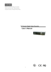
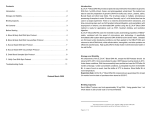
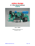
1
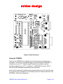
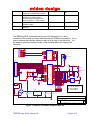
midon design
A Temperature Logging Serial Interface
TEMP05
Introduction ...........................................................................................................1
Using the TEMP05................................................................................................3
TEMP05 Commands.............................................................................................5
Jumper Definitions ................................................................................................7
What the heck is J6?.............................................................................................7
Software Change History ......................................................................................7
Legal Disclaimer ...................................................................................................8
Introduction
Thank you for your purchase of the TEMP05 kit. The following instructions
assume that you have properly assembled the units according to instructions and
that preliminary tests have been run.
To complete this project, you will need to connect a 12 to 16 Volt (AC or DC)
transformer to the terminal J1 (see Figure 2 for location of J1). If you are using
the auxiliary RELAY05 unit with TEMP05, choose a transformer that is as close
to 12 Volts as possible and that provides at least 0.7 Amperes. Otherwise, any
12 to 16 Volt adapter capable of at least 100mA will do.
TEMP05 User Guide Version Hb
Page 1 of 9
midon design
If you are using a sensor network of DS1820's for temperature readings, connect
them now to connector J2. Only 2 pins of each DS18S20 need be connected,
however a connection is required between the VDD and GND pins of the
DS1820 if you are using parasitic power. See Figure's 1 and 2 for connections.
On Rev G or higher PCB’s, a third terminal on J2 is provided for distributing +5V
to the one-wire bus.
.
Figure 1 DS18S20 Pin-out
If you are using a Dallas Semiconductor One-Wire Weather Station Version 1,
then remove the jumper H1 located on connector J4. Refer to Figure 2 for the
location of this jumper. If you are using a Dallas Semiconductor One-Wire
Weather Station Version 3, then add jumper to position H3 and make sure that a
jumper is also installed in position H1.
If you are using a Dallas Semiconductor Rain Gauge, then remove the jumper H2
located on connector J4. Refer to Figure 2 for the location of this jumper.
If you require stronger signal strength for sensors located far away from the
TEMP05, then install a jumper to connector J5 (Note: this is only applicable to
software 4.20 or less and PCB’s Rev F or lower).
Pre-assembled versions of this project include H1, H2 and J5 jumpers preinserted. J5 is not available on PCB rev G or higher.
TEMP05 User Guide Version Hb
Page 2 of 9
midon design
Figure 2 Parts Placement
Using the TEMP05
Power up the TEMP05 and configure the unit for the devices that you have
connected. Connect up a straight-through serial cable between TEMP05's P1
connector and your PC. Open up HyperTerminal (or equivalent terminal
emulator program) on your PC. Configure it to 9600 BPS, No parity, 8 bits, 1
start bit and NO hardware handshaking (very important!).
Issue an INI command to configure any connected sensors on the One Wire bus.
If you get any error messages, it is most likely a result of a bad connection to the
DS1820(s). Verify the connections.
TEMP05 User Guide Version Hb
Page 3 of 9
midon design
Now program the configuration by using the SET command. Just type SET and
the program will prompt you for the 2 required settings, logging interval and
Fahrenheit/Celsius (F/C) display. Pre-assembled units are pre-configured for 1
minute logging interval and Fahrenheit display.
If you also have a Version 1 One Wire Weather Station (OWWS), connect it up to
the one-wire port J2. The setup process for a V1 OWWS is slightly more
complex. I recommend that you first configure the OWWS using the Dallas
Semiconductor software and instructions provided. If you have the OWWS up
and running, shut down the software that is controlling it, locate the file INI.TXT
that was generated by that software, and transfer the INI.TXT file to the TEMP05.
You can use Hyperterm, or any equivalent communication package, to transfer
the file. First issue the ONE command to the TEMP05, followed by an ASCII
download of the INI.TXT file. Alternatively, you can simply type in the serial
numbers that are in the INI.TXT file. Use the EEP command to enter them. Start
at address 0 (use EEP 00).
If you are using the optional rain gauge and a version 1 OWWS, then the INI.TXT
file will be truncated before reaching the rain gauge's serial numbers. No
problem! Simply issue the INI command (with the rain gauge connected) after
installing the weather station. The TEMP05 will locate the rain gauge and set
itself up to use it.
If you have a version 3 One Wire Weather Station, installation is significantly
simpler. Attach the OWWS to J2. Issue an INI command. Next, issue a NOR
command to set the proper direction for North. Done! If you are also using a
Rain Gauge, then attach it now and issue another INI command.
If you are using a wind direction sensor (any version), then ensure that the wind
direction polarity is set to your requirements. Use the REV command if
necessary.
TEMP05 User Guide Version Hb
Page 4 of 9
midon design
TEMP05 Commands
Table 1. Commands Available
Command
CRC
DIS
EEP
ERA
GET
HLP
HUM
INI
MEM
NOR
ONE
QTY
REV
RLB
Description
Check all device checksums
Display serial numbers of all
configured One-Wire devices
Display and change specific
EEPROM memory locations
Erase the EEPROM
Obtain and display wind and rain.
Display a list of available commands
Request and display humidity sensor
readings
Search for a list of available
DS18S20's and rain gauge
Display and change specific memory
locations
Set North for a One Wire Weather
Station
Begin receipt of a Dallas
Semiconductor V1 One Wire Weather
Station INI.TXT file
Display a count of DS18S20 Sensors
Will reverse the wind direction to
compensate for a reversed board in a
One Wire Weather Station. North will
stay N, and South will stay S, but East
will become W, West will become E,
etc.
Actuate all relays at once
RLT
Set the relay off timer. This timer will
turn off all relays y minutes after the
last RLYxOn command.
RLY
Actuate a specific relay
RST
SET
Reset the Rain Gauge counter
Configure the interval and F/C display
TEMP05 User Guide Version Hb
Syntax
CRC
DIS
Available in
V4.14 or higher
EEP <start location>
all
ERA
GET
HLP
HUM
all
all
all
V4.14 or higher
INI
all
MEM <start location>
all
NOR
V4.17 or higher
ONE
all
QTY
REV
V4.15 or higher
V4.18 or higher
RLB x where x = an 8
bit binary number
representing all
relays. The MSB is
relays 8 and a 1 turns
on a relay.
RLT
You will be prompted
for the relay timer
value in decimal
minutes.
RLY <relay number>
<on|off>
where <relay
number> = 1 to 8 or
A for All.
V4.17 or higher
RLY S (displays
status of all relays)
RST
SET
all
V4.18 or higher
all
all
all
Page 5 of 9
midon design
SID
Enables or disables serial number
display for the temperature sensors.
Display temperatures of all connected
DS18S20's in either verbose
(includes serial numbers) or nonverbose (similar to GET) manner
Displays the current version of the
software loaded
Display 16 bytes of memory in HEX
and ASCII
TMP
VER
VIE
SID <on|off>
all
TMP
all
VER
all
VIE <start location>
all
The MEM and EEP commands can be used for debugging, but I don’t
recommend this unless you know what the memory locations are used for. If you
want to explore the software, please e-mail us for a copy of the listing file. You
will need to quote the version number of the software when you request the
listing file.
P1
U4
5
9
4
8
3
7
2
6
1
5
18
4
19
11
15
16
10
DB9
To User Terminal
T1OUT
T2OUT
R1IN
R2IN
C2+
C2+
C2C2-
MAX233
T1IN
T2IN
R1OUT
R2OUT
C1+
C1VVV+
2
1
3
20
8
13
12
17
14
D2
LED Bipolar
J3
1
2
3
4
5
6
7
8
9
10
11
12
13
14
15
16
U1
C3
11
10
9
8
7
6
5
4
22pFd
R2
10M
39
38
Y1
4.0MHz
37
R3A
16 pin DIP
C2
29
34
36
2
1
22pFd
C
R3A
+5V
10K
C
10K
J1
1
2
+
+5V
40
PA0
PA1
PA2
PA3
PA4
PA5
PA6
PA7
PB0
PB1
PB2
PB3
PB4
PB5
PB6
PB7
OSC1
OSC2
PC0
PC1
PC2
PC3
PC4
PC5
PC6
PC7
TCAP
PD0
PD5
PD7
IRQ
RST
VDD
C1
10uFd
PD1
PD4
PD2
PD3
TCMP
Term
12
13
14
15
16
17
18
19
R5
1.5K
D9
1N4148
DATA
CS1
28
27
26
25
24
23
22
21
30
33
31
32
+5V
LED1
LED2
One-Wire Bus
1
2
3
4
5
6
7
8
CLK
DO
DI
CON8
D4
J2
J4
1
2
3
1N4148
CON3
+5V
U2
1
2
3
4
CS
CLK Test
DI ORG
DO
7
6
93C56
35
68HC705C8
Power & Ground Table
2 -
1
+
C5
1000uFd
IN
Out
U4 VCC=7 GND=6,9
+5V
3
+
C4
100uFd
U2 VCC=8 GND=5
C6
0.1uFd
2
3
BRIDGE
U3
LM78L05
C
C
C
C
C
C
C
+ 4
GND
1
U1 Vcc =40 Gnd=20
D1
Title
Size
A
Date:
TEMP05 - One Wire Thermometer Sy stem
Document Number
SD000101
Rev
04
Sunday , December 09, 2001
Sheet
Figure 3 TEMP05 Schematic Diagram (REV G)
TEMP05 User Guide Version Hb
Page 6 of 9
2
of
2
midon design
Jumper Definitions
Jumper
J4 H1
J4 H2
J4 H3
J4 H4
J5
Meaning if installed
Meaning if not installed
No V1 OWWS connected
A V1 OWWS is connected
No Rain Gauge connected
A Dallas Rain Gauge is connected
A V3 OWWS is connected
No V3 OWWS is connected
Not defined
Not defined
Boost drive current
No Boost current is provided to the sensors
available
Note: units shipped with V4.21, or higher, software will not include a jumper for
J5. The connection will be permanent. PCB’s with rev G or higher will not have a
Jumper J5.
Note: H1 and H3 are mutually inclusive. Here are the valid combinations:
H1
installed
installed
not installed
not installed
H3
installed
not installed
installed
not installed
Valid?
Yes - a V3 OWWS is connected
Yes - no OWWS is connected
NO
Yes - a V1 OWWS is connected
What the heck is J6?
On rev G or higher PCB’s, there is a spot for inserting a RJ-11, RJ-12, or iButton
holder. This location is connected to the One Wire bus and can be used for
adding connectivity to One Wire busses configured for RJ-11/12 connection.
This can also be used, but not at the same time, as a place to insert an iButton.
A Dallas/Maxim iButton holder DS9094F is required to use J6 for iButton
connection.
Software Change History
Version Date
4.25
2/11/02
4.24
4.23
2/10/02
12/15/01
4.22
10/26/01
4.21
9/1/2001
Major Changes from Previous Loads
Added 93C66 EEPROM capabilities with an autocheck on power up for EEPROM type.
Minor tweaks to code size
Added parasitic check and display for DIS and QTY
commands.
Fixed HUM command to ensure continuation of
humidity readings even after an error on one reading.
Added support for DS18B20 and DS1822
temperature sensors. Added check on OW bus for
shorts or reversed sensors. QTY command now
counts DS18S20, DS18B20 and DS1822 sensors
TEMP05 User Guide Version Hb
Page 7 of 9
midon design
4.20
4.17
8/30/200
1
8/10/200
1
7/22/200
1
7/9/2001
4.16
7/7/2001
4.15
6/16/200
1
5/27/200
1
5/12/200
1
3/20/200
1
4.19
4.18
4.14
4.13
4.12
separately. Changed sensor numbering to start at 1
instead of zero.
Fixed bug in 4.19 - will only read 1 humidity sensor.
Code compaction only
Added REV and RLT commands.
Added support for V3 OWWS by AAG. Added NOR
command to set true north on OWWS. Added RLB
command to control all Relays at once.
Beta version of DS2450 based weather station
support
Added QTY command
Added capability of connecting multiple humidity
sensors
Added CRC command
Added humidity sensor capability and increased
temperature display precision
Your comments are appreciated. If you would like to submit feature requests or
product recommendations, please e-mail us.
Please also check the Frequently Asked Questions link on the TEMP05 web
page.
Legal Disclaimer
YOUR USE OF THIS PRODUCT IS AT YOUR OWN RISK. YOU ASSUME
FULL RESPONSIBILITY AND RISK OF LOSS RESULTING FROM THE USE
OF THIS PRODUCT. MIDON DESIGN WILL NOT BE LIABLE FOR ANY
DIRECT, SPECIAL, INDIRECT, INCIDENTAL, CONSEQUENTIAL OR
PUNITIVE DAMAGES OR ANY OTHER DAMAGES WHATSOEVER,
WHETHER IN AN ACTION BASED UPON A STATUTE, CONTRACT, TORT
(INCLUDING, WITHOUT LIMITATION NEGLIGENCE) OR OTHERWISE,
RELATING TO THE USE OF THIS PRODUCT.
Thank you!
[email protected]
TEMP05 User Guide Version Hb
Page 8 of 9
midon design
© Copyright 2001-2002 Midon Design. All rights reserved. No part of this
document may be reproduced, recorded, transmitted or distributed in any form or
by any means without the written consent of Midon Design.
End of Document
TEMP05 User Guide Version Hb
Page 9 of 9